EP3735558B1 - Module d'éclairage et kit d'éclairage - Google Patents
Module d'éclairage et kit d'éclairage Download PDFInfo
- Publication number
- EP3735558B1 EP3735558B1 EP18816107.9A EP18816107A EP3735558B1 EP 3735558 B1 EP3735558 B1 EP 3735558B1 EP 18816107 A EP18816107 A EP 18816107A EP 3735558 B1 EP3735558 B1 EP 3735558B1
- Authority
- EP
- European Patent Office
- Prior art keywords
- lighting
- light
- lighting module
- region
- acoustically absorbent
- Prior art date
- Legal status (The legal status is an assumption and is not a legal conclusion. Google has not performed a legal analysis and makes no representation as to the accuracy of the status listed.)
- Active
Links
Images


Classifications
-
- F—MECHANICAL ENGINEERING; LIGHTING; HEATING; WEAPONS; BLASTING
- F21—LIGHTING
- F21V—FUNCTIONAL FEATURES OR DETAILS OF LIGHTING DEVICES OR SYSTEMS THEREOF; STRUCTURAL COMBINATIONS OF LIGHTING DEVICES WITH OTHER ARTICLES, NOT OTHERWISE PROVIDED FOR
- F21V33/00—Structural combinations of lighting devices with other articles, not otherwise provided for
- F21V33/006—General building constructions or finishing work for buildings, e.g. roofs, gutters, stairs or floors; Garden equipment; Sunshades or parasols
-
- F—MECHANICAL ENGINEERING; LIGHTING; HEATING; WEAPONS; BLASTING
- F21—LIGHTING
- F21V—FUNCTIONAL FEATURES OR DETAILS OF LIGHTING DEVICES OR SYSTEMS THEREOF; STRUCTURAL COMBINATIONS OF LIGHTING DEVICES WITH OTHER ARTICLES, NOT OTHERWISE PROVIDED FOR
- F21V33/00—Structural combinations of lighting devices with other articles, not otherwise provided for
- F21V33/0004—Personal or domestic articles
- F21V33/0052—Audio or video equipment, e.g. televisions, telephones, cameras or computers; Remote control devices therefor
- F21V33/0056—Audio equipment, e.g. music instruments, radios or speakers
-
- F—MECHANICAL ENGINEERING; LIGHTING; HEATING; WEAPONS; BLASTING
- F21—LIGHTING
- F21S—NON-PORTABLE LIGHTING DEVICES; SYSTEMS THEREOF; VEHICLE LIGHTING DEVICES SPECIALLY ADAPTED FOR VEHICLE EXTERIORS
- F21S8/00—Lighting devices intended for fixed installation
- F21S8/04—Lighting devices intended for fixed installation intended only for mounting on a ceiling or the like overhead structures
-
- F—MECHANICAL ENGINEERING; LIGHTING; HEATING; WEAPONS; BLASTING
- F21—LIGHTING
- F21V—FUNCTIONAL FEATURES OR DETAILS OF LIGHTING DEVICES OR SYSTEMS THEREOF; STRUCTURAL COMBINATIONS OF LIGHTING DEVICES WITH OTHER ARTICLES, NOT OTHERWISE PROVIDED FOR
- F21V5/00—Refractors for light sources
- F21V5/02—Refractors for light sources of prismatic shape
-
- H—ELECTRICITY
- H04—ELECTRIC COMMUNICATION TECHNIQUE
- H04R—LOUDSPEAKERS, MICROPHONES, GRAMOPHONE PICK-UPS OR LIKE ACOUSTIC ELECTROMECHANICAL TRANSDUCERS; ELECTRIC HEARING AIDS; PUBLIC ADDRESS SYSTEMS
- H04R1/00—Details of transducers, loudspeakers or microphones
- H04R1/20—Arrangements for obtaining desired frequency or directional characteristics
- H04R1/22—Arrangements for obtaining desired frequency or directional characteristics for obtaining desired frequency characteristic only
- H04R1/28—Transducer mountings or enclosures modified by provision of mechanical or acoustic impedances, e.g. resonator, damping means
- H04R1/2869—Reduction of undesired resonances, i.e. standing waves within enclosure, or of undesired vibrations, i.e. of the enclosure itself
- H04R1/2876—Reduction of undesired resonances, i.e. standing waves within enclosure, or of undesired vibrations, i.e. of the enclosure itself by means of damping material, e.g. as cladding
-
- F—MECHANICAL ENGINEERING; LIGHTING; HEATING; WEAPONS; BLASTING
- F21—LIGHTING
- F21Y—INDEXING SCHEME ASSOCIATED WITH SUBCLASSES F21K, F21L, F21S and F21V, RELATING TO THE FORM OR THE KIND OF THE LIGHT SOURCES OR OF THE COLOUR OF THE LIGHT EMITTED
- F21Y2105/00—Planar light sources
- F21Y2105/10—Planar light sources comprising a two-dimensional [2D] array of point-like light-generating elements
-
- F—MECHANICAL ENGINEERING; LIGHTING; HEATING; WEAPONS; BLASTING
- F21—LIGHTING
- F21Y—INDEXING SCHEME ASSOCIATED WITH SUBCLASSES F21K, F21L, F21S and F21V, RELATING TO THE FORM OR THE KIND OF THE LIGHT SOURCES OR OF THE COLOUR OF THE LIGHT EMITTED
- F21Y2115/00—Light-generating elements of semiconductor light sources
- F21Y2115/10—Light-emitting diodes [LED]
Definitions
- the present invention relates to a lighting module configured to absorb acoustic waves.
- the present invention further relates to a lighting kit comprising a plurality of such lighting modules.
- SSL solid state lighting
- LED light emitting diode
- SSL solid state lighting
- m 2 square meters
- Such panels in some application domains are provided as at least part of the ceiling of such enclosed spaces, where they provide substantially homogeneous lighting emanating from parts of the ceiling defined by such panels.
- many LEDs may be suspended such that the LEDs face the highly reflective acoustic panels, thereby indirectly illuminating the light exit window of the lighting module, which may be defined by an acoustically transparent member such as a woven or knitted fabric that allows the sound waves to travel through the light exit window such that they can be dampened by the glass fibre panels within the housing.
- an acoustically transparent member such as a woven or knitted fabric that allows the sound waves to travel through the light exit window such that they can be dampened by the glass fibre panels within the housing.
- Materials such as plastics and glass are unsuitable as the light exit window material of choice due to their high acoustic reflectivity.
- the optical reflectivity of typical glass fibre panels is limited to 80-85%, which is suboptimal in particular in large area applications. This may be improved using advanced coatings such as sol-gel coatings, but this often is cost-prohibitive.
- US2015/0136521 A1 discloses an acoustic panel comprising a plurality of parallel-arranged elongated cavities, wherein each cavity has a first cavity wall and a second cavity wall tapering to a cavity back end and defining a cavity opening angle (Y) having a value in the range of 0° ⁇ Y ⁇ 90°, wherein the first cavity wall and the second cavity wall comprise a light-reflective material, wherein each elongated cavity at the cavity back end of the elongated cavity accommodates a light source having a light exit surface, wherein the first cavity walls hide the light exit surfaces of the light sources when the acoustic panel is viewed along a normal to the acoustic panel, and wherein the acoustic panel further comprises sound reducing material.
- this solution provides excellent acoustic dampening in a cost-effective manner, its optical performance is still not optimal due to a large fraction of the light emitted by the light sources being incident onto the cavity walls, causing optical losses.
- US2013/201790 A1 discloses a luminaire having a plurality of illumination devices.
- Each illumination device has a cup-shaped reflector that is made of an acoustically absorbing material.
- the reflector borders with an outer edge on a light emission window.
- the reflector and the light emission window together constitute a boundary of a reflector cavity.
- the reflector has a center through which an axis extends. The axis coincides with an optical axis of the illumination device and it extends transversely to the light emission window.
- a light source is provided on a lamp holding means. The light source is arranged to emit light in a direction transverse to the axis and towards the diffusely reflective surface of the reflector.
- the present invention seeks to provide a cost-effective lighting module configured to effectively absorb acoustic waves whilst also having good optical performance.
- the present invention further seeks to provide a lighting kit comprising a plurality of such lighting modules.
- a lighting module comprising a carrier having a major surface.
- the lighting module further comprises an optically transmissive light exit structure facing the major surface and being spatially separated therefrom.
- the major surface of the carrier includes a plurality of first regions and a plurality of second regions.
- the plurality of first regions and the plurality of second regions are arranged in a checkerboard pattern on the major surface.
- Each second region is adjacent to a first region.
- Each first region of said carrier has at least one light engine.
- Each first region is covered by a separate cover that is optically transmissive and acoustically reflective.
- Each cover has a pyramidal shape comprising a surface portion with a surface normal under a non-zero angle with the surface normal of the light exit structure so that it is shaped to reflect sound waves towards an adjacent second region.
- Each second region of said carrier has an acoustically absorbent member arranged to absorb said reflected sound waves.
- the term "light engine” refers to a light source comprising one or more solid state lighting elements, such as LEDs, thereby providing a particularly energy-efficient lighting module.
- Embodiments of the present invention are based on the insight that optically transmissive covers made of an acoustically reflective material, e.g. polymers or plastics such as poly (methylmethacrylate) (PMMA), polyethylene terephthalate (PET), polycarbonate (PC) and so on, glass, and other suitable materials, may be used to effectively deflect impending sound waves towards the second regions of the lighting module, whilst allowing a large portion of the light emitted by the light engines to pass through the cover and exit the lighting module, e.g.
- an acoustically reflective material e.g. polymers or plastics such as poly (methylmethacrylate) (PMMA), polyethylene terephthalate (PET), polycarbonate (PC) and so on, glass, and other suitable materials.
- PMMA poly (methylmethacrylate)
- PET polyethylene terephthalate
- PC polycarbonate
- the acoustically absorbent member may have a light-reflective coating such that light generated by the light engines that is incident on the acoustically absorbent members in the second regions is reflected rather than absorbed.
- the acoustically absorbent member may comprise at least one of a foam material, e.g. a melamine foam, glass wool and a micro-perforated member such as a micro-perforated plate, which may be folded.
- a foam material e.g. a melamine foam, glass wool
- a micro-perforated member such as a micro-perforated plate, which may be folded.
- Such a member may for example be a metal plate with small holes, e.g. perforations, carrying a high reflective optical coating or a high reflective white plastic material such as MCPET as marketed by the Furukawa electric group, Japan or ReftelasTM as marketed by the Sekisui Plastics company, Japan.
- the carrier also may be at least partially made of an acoustically absorbent material to further enhance the acoustic dampening properties of the lighting module.
- each first region comprises an acoustically absorbent recess housing the at least one light engine such that sound waves entering the recess are absorbed, thereby further improving the acoustic properties of the lighting module.
- each acoustically absorbent recess may have a light-reflective inner surface to reduce light losses caused by the absorption of light by the walls of the acoustically absorbent recesses.
- Each light engine is covered by a separate cover, and the first and second regions are arranged in a checkerboard pattern, wherein each first region comprises one light engine.
- Each cover is a multi-faceted cover that scatters incident sound waves into multiple directions, i.e. towards multiple adjacent second regions in which the acoustically absorbent material is located.
- Each cover has a pyramidal shape, such as a three-sided or four-sided pyramidal shape.
- each cover covers a plurality of light engines, e.g. in case of elongate first regions such as elongate channels, each such elongate first region housing a linear array of light engines.
- the light exit surface is an optically transmissive light exit structure such as a cloth or a micro-perforated foil facing and spanning the major surface and being spatially separated therefrom in order to obscure the internals of the lighting module from direct view, thereby enhancing the aesthetic appearance of the lighting module.
- a light exit structure may further act as a diffuser to further tune the optical performance of the lighting module.
- each cover has at least one surface region having a surface normal under a non-zero angle with the surface normal of said light exit structure such that such incident sound waves are deflected towards the second regions in which the acoustically absorbing material is located.
- the plurality of first regions and the plurality of second regions may be arranged on the major surface in a regular pattern, such as for example a striped or zebra pattern, a checkerboard pattern, a honeycomb pattern and so on.
- a lighting kit comprising a plurality of lighting modules of any of the herein described embodiments, wherein the lighting modules are configured to be coupled to each other.
- large area lighting panels may be constructed in a modular manner by combining a plurality of the lighting modules according to one or more embodiments of the present invention, thereby significantly reducing the manufacturing complexity of such large area lighting panels.
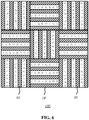
- the sound absorbing characteristics of such lighting panels can be made directionally independent by assembly of such lighting panels using lighting modules in different orientations within the lighting panel, e.g. using lighting modules having an arrangement of first and second regions in a striped or zebra pattern in which the orientation of neighboring lighting modules within the panel are rotated relative to each other by 90°.
- Such a modular lighting kit may further comprise a cloth for spanning across the lighting modules when coupled together, e.g. to form a lighting panel, in order to obscure said lighting modules from direct view, thereby obviating the need for individual lighting modules to comprise a previously explained light exit structure such as a cloth.
- FIG. 1 schematically depicts a top view of the internals of a lighting module 10 according to embodiments of the present invention explaining its operational principle.
- the lighting module 10 comprises a plurality of light engines 40 (of which for the sake of clarity only one is shown in FIG. 1 ) such as one or more SSL elements, e.g. LEDs that are arranged to direct their luminous output towards a light exit structure 50 such as a light exit window of the lighting module 10 through a light transmissive cover 30 of the light engine 40, which light transmissive cover 30 maybe transparent, translucent or diffusive.
- a light engines 40 such as one or more SSL elements, e.g. LEDs that are arranged to direct their luminous output towards a light exit structure 50 such as a light exit window of the lighting module 10 through a light transmissive cover 30 of the light engine 40, which light transmissive cover 30 maybe transparent, translucent or diffusive.
- the light transmissive cover 30 is made of a material that has a high acoustic reflectivity, for example an acoustic reflectivity of at least 70%, preferably of at least 80%, more preferably of at least 90%, which percentage expresses the fraction of sound waves 33 incident on the light transmissive cover 30 that deflect the sound waves 33 in another direction.
- the light transmissive cover 30 may be made of any material having optically transmissive and acoustically reflective properties, e.g. polymers such as PMMA, PET, PC and the like or glass materials.
- the light transmissive cover 30 is typically shaped such that a surface portion of the light transmissive cover 30 has a surface normal 31 under a non-zero angle ⁇ with the surface normal 51 of the light exit structure 50 such that sound waves 33 incident on this surface portion are deflected to a region adjacent to the light engine 40 in which an acoustically absorbent member 35 is located such that the deflected sound waves 33 are absorbed by this material.
- the angle ⁇ typically is larger than 0° and smaller than 90°, and may lie in a range of 10-80°, a range of 20-70°, or a range of 30-60°.
- the lighting module 10 has a plurality of first regions, each first region housing one or more light engines 40, each first region being adjacent to a second region comprising the acoustically absorbent member 35. Consequently, due to the acoustically reflective nature of the cover(s) 30, the acoustic absorbance or dampening of the light module 30 is comparable with prior art light modules in which the entire surface is covered in such an acoustically absorbent member 35.
- the acoustically absorbent member 35 has multiple surfaces capable of absorbing sound waves 33; for example, a rectangular bar-shaped acoustically absorbent member 35 has three exposed surfaces that can receive sound waves 33, i.e. a first surface facing the light exit structure 50 that can absorb sound waves 33 passing through the light exit structure 50 that are directly incident on the first surface and a pair of side surfaces extending from the first surface that can absorb deflected sound waves by adjacent light transmissive covers 30.
- the light transmissive cover 30 may have a continuous surface facing the light exit structure 50, e.g. a conical surface or another shape curved surface, or may have a multi-faceted surface facing the light exit structure 50 such as a polygonal surface, e.g. an elongated triangular surface, a 3-sided or 4-sided pyramidal surface, a hexagonal tiled surface, an octagonal tiled surface, and so on.
- the light transmissive cover 30 is formed as a baffled plate. Other suitable shapes for the light transmissive cover 30 will be immediately apparent to the skilled person.
- Each first region is covered by a separate cover 30 that is optically transmissive and acoustically reflective.
- the light transmissive cover 30 may cover a plurality of light engines 40, e.g. a plurality of SSL elements, which may be arranged as a linear array of SSL elements, or alternatively each light engine 40 may be covered by a separate light transmissive cover 30.
- the light transmissive cover 30 may operate as a mixing chamber for the light generated by the one or more light engines 40 it covers and may further perform an optical function, e.g. act as a diffuser, lens, collimator or the like of the light output produced by the one or more light engines 40 it covers.
- the acoustically absorbent member 35 may have any suitable shape, such as a block having a rectangular cross-section. Other cross-sectional shapes are equally feasible. In an embodiment, the cross-sectional shape of the acoustically absorbent member 35 is tuned to maximize the width of the acoustic wavelength spectrum it can absorb. For example, the cross-sectional shape of the acoustically absorbent member 35 may have a bar shape, trapezoidal shape, wedge shape or the like for this purpose. The acoustically absorbent member 35 may be formed from multiple acoustically absorbent material portions for this purpose.
- a rectangular bar-shaped acoustically absorbent member 35 formed from opposing wedge portions will have different acoustic absorption characteristics compared to a rectangular bar-shaped acoustically absorbent member 35 formed from a single piece of acoustically absorbent material.
- the acoustically absorbent member 35 may comprise one or more acoustically absorbent materials, which may be any suitable material capable of effectively absorbing sound waves 33. Many of such materials are well-known per se, such as fibrous materials that are commonly deployed in traditional acoustic tiles, such as glass wool, foam-based materials such as a melamine foam, polyurethane foam, and so on, as well as micro-perforated plates. Such micro-perforated plates may have a surface area of which about 0.2-0.5% is perforated with microscopic holes having a diameter in a range of 0.05-0.5 mm although other dimensions are of course equally feasible. Such micro-perforated plates may be folded in order to achieve the desired dimensions of the acoustically absorbent member 35.
- the acoustically absorbent material e.g. the micro-perforated plate or any other acoustically absorbent material, maybe filled with a substance, e.g. glass wool, which increases the acoustic absorbance of the acoustically absorbent material to further improve the acoustic performance of the lighting module 10.
- the acoustically absorbent member 35 preferably is covered by a light-reflective coating, e.g. a white paint coating or a reflective foil, in order to minimize light losses of light generated by the light engines 40 that is incident on the acoustically absorbent member 35.
- the light engines 40 are solid state lighting elements such as LEDs.
- the light engines 40 may be arranged to directly or indirectly illuminate the light transmissive cover 30.
- the light module 10 may comprise an arrangement of reflectors or reflective surfaces, e.g. of a cavity in which the light engine 40 is housed, which redirect the luminous output distribution of the light engines 40 towards their light transmissive cover 30.
- the light engines 40 are arranged in a direct lit arrangement to optimize the optical performance of the light module 10.
- FIG. 2 schematically depicts a cross-sectional view of a lighting module 10 according to an example embodiment.
- the lighting module 10 comprises a carrier 20 having a major surface 21 comprising a plurality of first regions 23 in each of which one or more light engines 40 are positioned, i.e. carried by the carrier 20, with each first region 23 comprising at least one adjacent second region 25 carrying an acoustically absorbent member 35.
- Each first region 23 further comprises a light transmissive cover 30 covering the one or more light engines 40 present in that first region 23 such that the light emitted by the light engines 40 passes through the light transmissive cover 30 and exits the lighting module 10 through its light exit structure 50 opposite the first major surface 21 of the carrier 20.
- the carrier 20 may be made of or comprise any suitable materials, e.g. acoustically reflective materials such as metal or wood, acoustically absorbent materials such as glass wool, and so on.
- the carrier may be a solid structure, e.g. a continuous metal or wood panel, or an open structure, e.g. a metal frame or the like.
- the light exit structure 50 may be an aperture in some embodiments or in alternative embodiments may comprise an acoustically transmissive member such as a cloth or the like such that the internals of the lighting module 10 are obscured from direct view by the acoustically transmissive member defining the light exit structure 50 whilst sound waves 33 can penetrate the lighting module 10 through the acoustically transmissive member and be absorbed either directly by the one or more acoustically absorbent members 35 or can be reflected onto the one or more acoustically absorbent members 35 by the one or more light transmissive covers 30 as explained in more detail above.
- the cloth may be spanned across the entire surface of the lighting module 10 as will be understood by the skilled person.
- a plurality of lighting modules 10 maybe provided as a lighting kit in which the lighting modules 10 may be combined to form a large area lighting apparatus, e.g. a lighting panel having a surface area of several square meters, in which case such a cloth may be spanned across the assembled lighting panel rather than across individual lighting modules 10.
- a large area lighting apparatus can be built up by similar lighting modules 10, e.g.
- each lighting module 10 may be provided with a mating mechanism, such as a tongue and groove mechanism, a male-female click mechanism or the like that facilitates the coupling together of individual lighting modules 10.
- a mating mechanism such as a tongue and groove mechanism, a male-female click mechanism or the like that facilitates the coupling together of individual lighting modules 10.
- such a mating mechanism may be provided on one or more of the side surfaces defining the housing of the lighting module 10.
- FIG. 3 schematically depicts a cross-sectional view of a lighting module 10 according to another example embodiment in which the carrier 20 comprises a plurality of cavities 27, each cavity 27 housing one or more light engines 40.
- the carrier 20 may be made of an acoustically absorbent material in this embodiment such that sound waves 22 penetrating the cavities 27 are also absorbed, thereby further improving the acoustic performance of the lighting module 10.
- the internal surfaces or at least the sidewalls of each cavity 27 carries a light-reflective layer such as a white paint coating or a light reflective foil in order to increase the amount of light generated by the one or more light engines 40 exiting the cavity 27 and subsequently the lighting module 10 through its light exit structure 50.
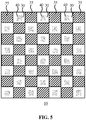
- the first regions 23 and the second regions 25 on the major surface 21 of the carrier 20 may define a regular pattern of regions, such as the striped or zebra pattern schematically depicted in FIG. 4 , which shows a top view of a lighting module 10 through the light exit structure 50 (not shown) according to an example embodiment or the checkerboard pattern schematically depicted in FIG. 5 , which shows a top view of a lighting module 10 through the light exit structure 50 (not shown) according to another example embodiment.
- Other regular patterns e.g. a honeycomb pattern, a triangular pattern and so on, are of course equally feasible.
- each light engine 40 may be covered by an individual light transmissive cover 30.
- each first region 23 houses one light engine 40, wherein each light engine 40 is covered by its own light transmissive cover 30.
- the light transmissive cover 30 maybe a pyramidally shaped cover that deflects incident sound waves 33 onto the acoustically absorbent members 35 in the second regions 25 adjacent to the first region 23 as previously explained.
- a plurality of lighting modules 10 may be provided as a lighting kit in which the lighting modules 10 can be assembled into a large area lighting apparatus.
- the lighting modules 10 comprise such a regular pattern as explained above, the thus assembled lighting apparatus has substantially homogenous sound absorbing characteristically across its surface area, in particular where identical lighting modules 10 have been used in the lighting kit.
- the lighting kit may comprise lighting modules 10 having different regular patterns such that the overall acoustic performance of the assembled large area lighting apparatus can be tuned by positioning of a lighting module 10 having a particular regular pattern within a particular location of the large area lighting apparatus.
- the overall acoustic performance of the large area lighting apparatus assembled from such lighting modules 10 may be directionally dependent if the directional regular patterns of all the lighting modules 10 are aligned in the assembled large area lighting apparatus.
- an alternating pattern of lighting modules 10 as schematically depicted in FIG. 6 may be assembled in which each lighting module 10 having its directional pattern extending in a first direction, e.g. a vertical direction, neighbors lighting modules 10' having its directional pattern extending in a second direction perpendicular to the first direction, e.g. a horizontal direction such that the overall acoustic behavior of the large area lighting apparatus 100 becomes directionally independent.
Landscapes
- Engineering & Computer Science (AREA)
- General Engineering & Computer Science (AREA)
- Multimedia (AREA)
- Signal Processing (AREA)
- Physics & Mathematics (AREA)
- Acoustics & Sound (AREA)
- Otolaryngology (AREA)
- Health & Medical Sciences (AREA)
- Architecture (AREA)
- Civil Engineering (AREA)
- Structural Engineering (AREA)
- Soundproofing, Sound Blocking, And Sound Damping (AREA)
- Arrangement Of Elements, Cooling, Sealing, Or The Like Of Lighting Devices (AREA)
- Planar Illumination Modules (AREA)
- Building Environments (AREA)
Claims (9)
- Module d'éclairage (10) comprenant :un support (20) présentant une surface principale (21) ; etune structure de sortie de lumière optiquement transmissive (50) faisant face à la surface principale (21) et étant spatialement séparée de celle-ci ;dans lequel la surface principale (21) du support (20) inclut une pluralité de premières régions (23) et une pluralité de secondes régions (25), la pluralité de premières régions (23) et la pluralité de secondes régions (25) étant agencées selon un motif en damier sur la surface principale (21), et chaque seconde région (25) étant adjacente à une première région (23) ;dans lequel chaque première région (23) dudit support (20) présente au moins un moteur de lumière (40) ;dans lequel chaque première région (23) est recouverte d'un couvercle (30) séparé qui est optiquement transmissif et acoustiquement réfléchissant ;dans lequel chaque couvercle (30) présente une forme pyramidale comprenant une partie de surface avec une normale de surface (31) sous un angle non nul (θ) avec la normale de surface (51) de la structure de sortie de lumière (50) de telle sorte qu'il est façonné pour réfléchir des ondes sonores (33) vers une deuxième région (25) adjacente ; etdans lequel chaque deuxième région (25) dudit support (20) présente un élément acoustiquement absorbant (35) agencé pour absorber lesdites ondes sonores (33) réfléchies.
- Module d'éclairage (10) selon la revendication 1, dans lequel l'élément acoustiquement absorbant (35) présente un revêtement réfléchissant la lumière.
- Module d'éclairage (10) selon la revendication 1 ou 2, dans lequel l'élément acoustiquement absorbant (35) comprend au moins un parmi un matériau de mousse, de la laine de verre et un élément micro-perforé.
- Module d'éclairage (10) selon l'une quelconque des revendications 1 à 3, dans lequel le support (20) est composé d'un matériau acoustiquement absorbant.
- Module d'éclairage (10) selon l'une quelconque des revendications 1-4, dans lequel chaque première région (23) comprend un évidement acoustiquement absorbant (27) logeant l'au moins un moteur de lumière (40).
- Module d'éclairage (10) selon la revendication 5, dans lequel l'évidement acoustiquement absorbant (27) présente une surface intérieure réfléchissant la lumière.
- Module d'éclairage (10) selon l'une quelconque des revendications 1-6, dans lequel la structure de sortie de lumière (50) est un tissu s'étalant sur la surface principale (21).
- Kit d'éclairage (100) comprenant une pluralité de modules d'éclairage (10) selon l'une quelconque des revendications 1-7, dans lequel les modules d'éclairage (10) sont configurés pour être couplés les uns aux autres.
- Kit d'éclairage (100) selon la revendication 8, comprenant en outre un tissu (50) pour s'étaler à travers les modules d'éclairage (10) lorsqu'ils sont couplés ensemble afin d'obscurcir lesdits modules d'éclairage de la vue directe.
Applications Claiming Priority (2)
| Application Number | Priority Date | Filing Date | Title |
|---|---|---|---|
| EP18150007.5A EP3505823A1 (fr) | 2018-01-02 | 2018-01-02 | Module d'éclairage et kit d'éclairage |
| PCT/EP2018/085422 WO2019134820A1 (fr) | 2018-01-02 | 2018-12-18 | Module d'éclairage et kit d'éclairage |
Publications (2)
| Publication Number | Publication Date |
|---|---|
| EP3735558A1 EP3735558A1 (fr) | 2020-11-11 |
| EP3735558B1 true EP3735558B1 (fr) | 2021-05-05 |
Family
ID=60915428
Family Applications (2)
| Application Number | Title | Priority Date | Filing Date |
|---|---|---|---|
| EP18150007.5A Ceased EP3505823A1 (fr) | 2018-01-02 | 2018-01-02 | Module d'éclairage et kit d'éclairage |
| EP18816107.9A Active EP3735558B1 (fr) | 2018-01-02 | 2018-12-18 | Module d'éclairage et kit d'éclairage |
Family Applications Before (1)
| Application Number | Title | Priority Date | Filing Date |
|---|---|---|---|
| EP18150007.5A Ceased EP3505823A1 (fr) | 2018-01-02 | 2018-01-02 | Module d'éclairage et kit d'éclairage |
Country Status (6)
| Country | Link |
|---|---|
| US (1) | US11143395B2 (fr) |
| EP (2) | EP3505823A1 (fr) |
| JP (1) | JP7231648B2 (fr) |
| CN (1) | CN111527346B (fr) |
| ES (1) | ES2880728T3 (fr) |
| WO (1) | WO2019134820A1 (fr) |
Families Citing this family (2)
| Publication number | Priority date | Publication date | Assignee | Title |
|---|---|---|---|---|
| MX2023004193A (es) | 2020-11-06 | 2023-05-03 | Knauf Gips Kg | Panel acustico perforado, metodo de produccion, y uso del mismo. |
| US11499687B1 (en) * | 2021-12-08 | 2022-11-15 | Elite Lighting | Troffer light fixture with cover containing lenses |
Family Cites Families (11)
| Publication number | Priority date | Publication date | Assignee | Title |
|---|---|---|---|---|
| US3665177A (en) * | 1970-12-28 | 1972-05-23 | Armstrong Cork Co | Shallow profile vaulted lighting module |
| JP4167570B2 (ja) * | 2003-09-11 | 2008-10-15 | 埼玉日本電気株式会社 | 携帯電子機器で用いられるイルミネーション構造、及び該構造を備える携帯電子機器 |
| KR100571539B1 (ko) | 2004-06-30 | 2006-04-24 | 김배영 | 흡음 블록 및 그 시공 방법 |
| EP2792936B1 (fr) * | 2010-09-30 | 2019-11-06 | Signify Holding B.V. | Dispositif d'éclairage |
| WO2013001430A1 (fr) * | 2011-06-30 | 2013-01-03 | Koninklijke Philips Electronics N.V. | Dispositif d'éclairage enrobé basé sur des del |
| WO2013038292A1 (fr) * | 2011-09-12 | 2013-03-21 | Koninklijke Philips Electronics N.V. | Unité de panneau de paroi sèche comprenant une pluralité de sources de lumière |
| US9147390B2 (en) | 2011-10-20 | 2015-09-29 | Koninklijke Philips N.V. | Optical acoustic panel |
| EP2836762B1 (fr) * | 2012-04-12 | 2016-07-06 | Koninklijke Philips N.V. | Élément de construction acoustique électroluminescent |
| CN105189886B (zh) * | 2012-06-20 | 2017-03-15 | 皇家飞利浦有限公司 | 具有照明性质的声学面板 |
| CN206626458U (zh) * | 2015-12-18 | 2017-11-10 | 飞利浦照明控股有限公司 | 灯具及照明系统 |
| CN112204300B (zh) * | 2018-04-06 | 2022-07-22 | 昕诺飞控股有限公司 | 吸声照明模块 |
-
2018
- 2018-01-02 EP EP18150007.5A patent/EP3505823A1/fr not_active Ceased
- 2018-12-18 CN CN201880085136.3A patent/CN111527346B/zh not_active Expired - Fee Related
- 2018-12-18 EP EP18816107.9A patent/EP3735558B1/fr active Active
- 2018-12-18 ES ES18816107T patent/ES2880728T3/es active Active
- 2018-12-18 JP JP2020555298A patent/JP7231648B2/ja active Active
- 2018-12-18 WO PCT/EP2018/085422 patent/WO2019134820A1/fr not_active Ceased
- 2018-12-18 US US16/958,718 patent/US11143395B2/en not_active Expired - Fee Related
Also Published As
| Publication number | Publication date |
|---|---|
| WO2019134820A1 (fr) | 2019-07-11 |
| US11143395B2 (en) | 2021-10-12 |
| EP3735558A1 (fr) | 2020-11-11 |
| CN111527346B (zh) | 2022-08-02 |
| JP7231648B2 (ja) | 2023-03-01 |
| JP2021508935A (ja) | 2021-03-11 |
| EP3505823A1 (fr) | 2019-07-03 |
| ES2880728T3 (es) | 2021-11-25 |
| CN111527346A (zh) | 2020-08-11 |
| US20210010670A1 (en) | 2021-01-14 |
Similar Documents
| Publication | Publication Date | Title |
|---|---|---|
| RU2660406C2 (ru) | Звукопоглощающая осветительная панель и модульная поверхностная система | |
| US9765516B2 (en) | Acoustically absorbing room divider | |
| CN102472860B (zh) | 自由形式照明模块 | |
| US20230417393A1 (en) | Light Emitting Device with Adaptable Glare Class | |
| EP3090206B1 (fr) | Carreau lumineux acoustique | |
| CN109477620B (zh) | 具有改进的输出均匀性的照明器 | |
| US11320139B2 (en) | Lighting module, kit and panel | |
| EP3735558B1 (fr) | Module d'éclairage et kit d'éclairage | |
| JP5816850B2 (ja) | 照明装置 | |
| US12025290B1 (en) | Acoustic lighting device | |
| KR100986782B1 (ko) | 발광다이오드를 이용한 평판조명장치 | |
| EP3803203B1 (fr) | Unité d'éclairage rigide | |
| CN110645511A (zh) | 光学装置以及照明装置 | |
| US7207699B2 (en) | System of light units | |
| RU2657466C2 (ru) | Осветительная полоса, осветительная система, опорный панельный элемент и модульная панельная система | |
| WO2019219520A1 (fr) | Panneau lumineux et kit d'éclairage | |
| JP2011171265A (ja) | 反射板および照明器具 |
Legal Events
| Date | Code | Title | Description |
|---|---|---|---|
| STAA | Information on the status of an ep patent application or granted ep patent |
Free format text: STATUS: UNKNOWN |
|
| STAA | Information on the status of an ep patent application or granted ep patent |
Free format text: STATUS: THE INTERNATIONAL PUBLICATION HAS BEEN MADE |
|
| PUAI | Public reference made under article 153(3) epc to a published international application that has entered the european phase |
Free format text: ORIGINAL CODE: 0009012 |
|
| STAA | Information on the status of an ep patent application or granted ep patent |
Free format text: STATUS: REQUEST FOR EXAMINATION WAS MADE |
|
| 17P | Request for examination filed |
Effective date: 20200803 |
|
| AK | Designated contracting states |
Kind code of ref document: A1 Designated state(s): AL AT BE BG CH CY CZ DE DK EE ES FI FR GB GR HR HU IE IS IT LI LT LU LV MC MK MT NL NO PL PT RO RS SE SI SK SM TR |
|
| AX | Request for extension of the european patent |
Extension state: BA ME |
|
| GRAP | Despatch of communication of intention to grant a patent |
Free format text: ORIGINAL CODE: EPIDOSNIGR1 |
|
| STAA | Information on the status of an ep patent application or granted ep patent |
Free format text: STATUS: GRANT OF PATENT IS INTENDED |
|
| DAV | Request for validation of the european patent (deleted) | ||
| DAX | Request for extension of the european patent (deleted) | ||
| INTG | Intention to grant announced |
Effective date: 20201204 |
|
| GRAS | Grant fee paid |
Free format text: ORIGINAL CODE: EPIDOSNIGR3 |
|
| GRAA | (expected) grant |
Free format text: ORIGINAL CODE: 0009210 |
|
| STAA | Information on the status of an ep patent application or granted ep patent |
Free format text: STATUS: THE PATENT HAS BEEN GRANTED |
|
| AK | Designated contracting states |
Kind code of ref document: B1 Designated state(s): AL AT BE BG CH CY CZ DE DK EE ES FI FR GB GR HR HU IE IS IT LI LT LU LV MC MK MT NL NO PL PT RO RS SE SI SK SM TR |
|
| REG | Reference to a national code |
Ref country code: GB Ref legal event code: FG4D |
|
| REG | Reference to a national code |
Ref country code: CH Ref legal event code: EP |
|
| REG | Reference to a national code |
Ref country code: AT Ref legal event code: REF Ref document number: 1390264 Country of ref document: AT Kind code of ref document: T Effective date: 20210515 |
|
| REG | Reference to a national code |
Ref country code: DE Ref legal event code: R096 Ref document number: 602018016867 Country of ref document: DE |
|
| REG | Reference to a national code |
Ref country code: IE Ref legal event code: FG4D |
|
| REG | Reference to a national code |
Ref country code: SE Ref legal event code: TRGR |
|
| REG | Reference to a national code |
Ref country code: LT Ref legal event code: MG9D |
|
| REG | Reference to a national code |
Ref country code: AT Ref legal event code: MK05 Ref document number: 1390264 Country of ref document: AT Kind code of ref document: T Effective date: 20210505 |
|
| PG25 | Lapsed in a contracting state [announced via postgrant information from national office to epo] |
Ref country code: LT Free format text: LAPSE BECAUSE OF FAILURE TO SUBMIT A TRANSLATION OF THE DESCRIPTION OR TO PAY THE FEE WITHIN THE PRESCRIBED TIME-LIMIT Effective date: 20210505 Ref country code: HR Free format text: LAPSE BECAUSE OF FAILURE TO SUBMIT A TRANSLATION OF THE DESCRIPTION OR TO PAY THE FEE WITHIN THE PRESCRIBED TIME-LIMIT Effective date: 20210505 Ref country code: FI Free format text: LAPSE BECAUSE OF FAILURE TO SUBMIT A TRANSLATION OF THE DESCRIPTION OR TO PAY THE FEE WITHIN THE PRESCRIBED TIME-LIMIT Effective date: 20210505 Ref country code: AT Free format text: LAPSE BECAUSE OF FAILURE TO SUBMIT A TRANSLATION OF THE DESCRIPTION OR TO PAY THE FEE WITHIN THE PRESCRIBED TIME-LIMIT Effective date: 20210505 Ref country code: BG Free format text: LAPSE BECAUSE OF FAILURE TO SUBMIT A TRANSLATION OF THE DESCRIPTION OR TO PAY THE FEE WITHIN THE PRESCRIBED TIME-LIMIT Effective date: 20210805 |
|
| REG | Reference to a national code |
Ref country code: ES Ref legal event code: FG2A Ref document number: 2880728 Country of ref document: ES Kind code of ref document: T3 Effective date: 20211125 |
|
| PG25 | Lapsed in a contracting state [announced via postgrant information from national office to epo] |
Ref country code: IS Free format text: LAPSE BECAUSE OF FAILURE TO SUBMIT A TRANSLATION OF THE DESCRIPTION OR TO PAY THE FEE WITHIN THE PRESCRIBED TIME-LIMIT Effective date: 20210905 Ref country code: GR Free format text: LAPSE BECAUSE OF FAILURE TO SUBMIT A TRANSLATION OF THE DESCRIPTION OR TO PAY THE FEE WITHIN THE PRESCRIBED TIME-LIMIT Effective date: 20210806 Ref country code: PT Free format text: LAPSE BECAUSE OF FAILURE TO SUBMIT A TRANSLATION OF THE DESCRIPTION OR TO PAY THE FEE WITHIN THE PRESCRIBED TIME-LIMIT Effective date: 20210906 Ref country code: RS Free format text: LAPSE BECAUSE OF FAILURE TO SUBMIT A TRANSLATION OF THE DESCRIPTION OR TO PAY THE FEE WITHIN THE PRESCRIBED TIME-LIMIT Effective date: 20210505 Ref country code: PL Free format text: LAPSE BECAUSE OF FAILURE TO SUBMIT A TRANSLATION OF THE DESCRIPTION OR TO PAY THE FEE WITHIN THE PRESCRIBED TIME-LIMIT Effective date: 20210505 Ref country code: LV Free format text: LAPSE BECAUSE OF FAILURE TO SUBMIT A TRANSLATION OF THE DESCRIPTION OR TO PAY THE FEE WITHIN THE PRESCRIBED TIME-LIMIT Effective date: 20210505 Ref country code: NO Free format text: LAPSE BECAUSE OF FAILURE TO SUBMIT A TRANSLATION OF THE DESCRIPTION OR TO PAY THE FEE WITHIN THE PRESCRIBED TIME-LIMIT Effective date: 20210805 |
|
| REG | Reference to a national code |
Ref country code: NL Ref legal event code: MP Effective date: 20210505 |
|
| PG25 | Lapsed in a contracting state [announced via postgrant information from national office to epo] |
Ref country code: NL Free format text: LAPSE BECAUSE OF FAILURE TO SUBMIT A TRANSLATION OF THE DESCRIPTION OR TO PAY THE FEE WITHIN THE PRESCRIBED TIME-LIMIT Effective date: 20210505 |
|
| PG25 | Lapsed in a contracting state [announced via postgrant information from national office to epo] |
Ref country code: EE Free format text: LAPSE BECAUSE OF FAILURE TO SUBMIT A TRANSLATION OF THE DESCRIPTION OR TO PAY THE FEE WITHIN THE PRESCRIBED TIME-LIMIT Effective date: 20210505 Ref country code: SK Free format text: LAPSE BECAUSE OF FAILURE TO SUBMIT A TRANSLATION OF THE DESCRIPTION OR TO PAY THE FEE WITHIN THE PRESCRIBED TIME-LIMIT Effective date: 20210505 Ref country code: SM Free format text: LAPSE BECAUSE OF FAILURE TO SUBMIT A TRANSLATION OF THE DESCRIPTION OR TO PAY THE FEE WITHIN THE PRESCRIBED TIME-LIMIT Effective date: 20210505 Ref country code: RO Free format text: LAPSE BECAUSE OF FAILURE TO SUBMIT A TRANSLATION OF THE DESCRIPTION OR TO PAY THE FEE WITHIN THE PRESCRIBED TIME-LIMIT Effective date: 20210505 Ref country code: DK Free format text: LAPSE BECAUSE OF FAILURE TO SUBMIT A TRANSLATION OF THE DESCRIPTION OR TO PAY THE FEE WITHIN THE PRESCRIBED TIME-LIMIT Effective date: 20210505 Ref country code: CZ Free format text: LAPSE BECAUSE OF FAILURE TO SUBMIT A TRANSLATION OF THE DESCRIPTION OR TO PAY THE FEE WITHIN THE PRESCRIBED TIME-LIMIT Effective date: 20210505 |
|
| REG | Reference to a national code |
Ref country code: DE Ref legal event code: R097 Ref document number: 602018016867 Country of ref document: DE |
|
| PLBE | No opposition filed within time limit |
Free format text: ORIGINAL CODE: 0009261 |
|
| STAA | Information on the status of an ep patent application or granted ep patent |
Free format text: STATUS: NO OPPOSITION FILED WITHIN TIME LIMIT |
|
| 26N | No opposition filed |
Effective date: 20220208 |
|
| PG25 | Lapsed in a contracting state [announced via postgrant information from national office to epo] |
Ref country code: IS Free format text: LAPSE BECAUSE OF FAILURE TO SUBMIT A TRANSLATION OF THE DESCRIPTION OR TO PAY THE FEE WITHIN THE PRESCRIBED TIME-LIMIT Effective date: 20210905 Ref country code: AL Free format text: LAPSE BECAUSE OF FAILURE TO SUBMIT A TRANSLATION OF THE DESCRIPTION OR TO PAY THE FEE WITHIN THE PRESCRIBED TIME-LIMIT Effective date: 20210505 |
|
| PG25 | Lapsed in a contracting state [announced via postgrant information from national office to epo] |
Ref country code: MC Free format text: LAPSE BECAUSE OF FAILURE TO SUBMIT A TRANSLATION OF THE DESCRIPTION OR TO PAY THE FEE WITHIN THE PRESCRIBED TIME-LIMIT Effective date: 20210505 |
|
| REG | Reference to a national code |
Ref country code: CH Ref legal event code: PL |
|
| REG | Reference to a national code |
Ref country code: BE Ref legal event code: MM Effective date: 20211231 |
|
| PG25 | Lapsed in a contracting state [announced via postgrant information from national office to epo] |
Ref country code: LU Free format text: LAPSE BECAUSE OF NON-PAYMENT OF DUE FEES Effective date: 20211218 Ref country code: IE Free format text: LAPSE BECAUSE OF NON-PAYMENT OF DUE FEES Effective date: 20211218 |
|
| PG25 | Lapsed in a contracting state [announced via postgrant information from national office to epo] |
Ref country code: BE Free format text: LAPSE BECAUSE OF NON-PAYMENT OF DUE FEES Effective date: 20211231 |
|
| PG25 | Lapsed in a contracting state [announced via postgrant information from national office to epo] |
Ref country code: LI Free format text: LAPSE BECAUSE OF NON-PAYMENT OF DUE FEES Effective date: 20211231 Ref country code: CH Free format text: LAPSE BECAUSE OF NON-PAYMENT OF DUE FEES Effective date: 20211231 |
|
| PGFP | Annual fee paid to national office [announced via postgrant information from national office to epo] |
Ref country code: SE Payment date: 20221223 Year of fee payment: 5 Ref country code: GB Payment date: 20221220 Year of fee payment: 5 Ref country code: FR Payment date: 20221222 Year of fee payment: 5 |
|
| PGFP | Annual fee paid to national office [announced via postgrant information from national office to epo] |
Ref country code: ES Payment date: 20230118 Year of fee payment: 5 |
|
| PGFP | Annual fee paid to national office [announced via postgrant information from national office to epo] |
Ref country code: IT Payment date: 20221222 Year of fee payment: 5 Ref country code: DE Payment date: 20230224 Year of fee payment: 5 |
|
| P01 | Opt-out of the competence of the unified patent court (upc) registered |
Effective date: 20230425 |
|
| PG25 | Lapsed in a contracting state [announced via postgrant information from national office to epo] |
Ref country code: CY Free format text: LAPSE BECAUSE OF FAILURE TO SUBMIT A TRANSLATION OF THE DESCRIPTION OR TO PAY THE FEE WITHIN THE PRESCRIBED TIME-LIMIT Effective date: 20210505 |
|
| PG25 | Lapsed in a contracting state [announced via postgrant information from national office to epo] |
Ref country code: HU Free format text: LAPSE BECAUSE OF FAILURE TO SUBMIT A TRANSLATION OF THE DESCRIPTION OR TO PAY THE FEE WITHIN THE PRESCRIBED TIME-LIMIT; INVALID AB INITIO Effective date: 20181218 |
|
| PG25 | Lapsed in a contracting state [announced via postgrant information from national office to epo] |
Ref country code: MK Free format text: LAPSE BECAUSE OF FAILURE TO SUBMIT A TRANSLATION OF THE DESCRIPTION OR TO PAY THE FEE WITHIN THE PRESCRIBED TIME-LIMIT Effective date: 20210505 |
|
| PG25 | Lapsed in a contracting state [announced via postgrant information from national office to epo] |
Ref country code: TR Free format text: LAPSE BECAUSE OF FAILURE TO SUBMIT A TRANSLATION OF THE DESCRIPTION OR TO PAY THE FEE WITHIN THE PRESCRIBED TIME-LIMIT Effective date: 20210505 |
|
| REG | Reference to a national code |
Ref country code: DE Ref legal event code: R119 Ref document number: 602018016867 Country of ref document: DE |
|
| REG | Reference to a national code |
Ref country code: SE Ref legal event code: EUG |
|
| GBPC | Gb: european patent ceased through non-payment of renewal fee |
Effective date: 20231218 |
|
| PG25 | Lapsed in a contracting state [announced via postgrant information from national office to epo] |
Ref country code: MT Free format text: LAPSE BECAUSE OF FAILURE TO SUBMIT A TRANSLATION OF THE DESCRIPTION OR TO PAY THE FEE WITHIN THE PRESCRIBED TIME-LIMIT Effective date: 20210505 |
|
| PG25 | Lapsed in a contracting state [announced via postgrant information from national office to epo] |
Ref country code: DE Free format text: LAPSE BECAUSE OF NON-PAYMENT OF DUE FEES Effective date: 20240702 |
|
| PG25 | Lapsed in a contracting state [announced via postgrant information from national office to epo] |
Ref country code: GB Free format text: LAPSE BECAUSE OF NON-PAYMENT OF DUE FEES Effective date: 20231218 |
|
| PG25 | Lapsed in a contracting state [announced via postgrant information from national office to epo] |
Ref country code: FR Free format text: LAPSE BECAUSE OF NON-PAYMENT OF DUE FEES Effective date: 20231231 |
|
| PG25 | Lapsed in a contracting state [announced via postgrant information from national office to epo] |
Ref country code: GB Free format text: LAPSE BECAUSE OF NON-PAYMENT OF DUE FEES Effective date: 20231218 Ref country code: FR Free format text: LAPSE BECAUSE OF NON-PAYMENT OF DUE FEES Effective date: 20231231 Ref country code: DE Free format text: LAPSE BECAUSE OF NON-PAYMENT OF DUE FEES Effective date: 20240702 |
|
| REG | Reference to a national code |
Ref country code: ES Ref legal event code: FD2A Effective date: 20250129 |
|
| PG25 | Lapsed in a contracting state [announced via postgrant information from national office to epo] |
Ref country code: ES Free format text: LAPSE BECAUSE OF NON-PAYMENT OF DUE FEES Effective date: 20231219 |
|
| PG25 | Lapsed in a contracting state [announced via postgrant information from national office to epo] |
Ref country code: IT Free format text: LAPSE BECAUSE OF NON-PAYMENT OF DUE FEES Effective date: 20231218 |
|
| PG25 | Lapsed in a contracting state [announced via postgrant information from national office to epo] |
Ref country code: SE Free format text: LAPSE BECAUSE OF NON-PAYMENT OF DUE FEES Effective date: 20231219 |