EP3735564B1 - Four - Google Patents
Four Download PDFInfo
- Publication number
- EP3735564B1 EP3735564B1 EP18731090.9A EP18731090A EP3735564B1 EP 3735564 B1 EP3735564 B1 EP 3735564B1 EP 18731090 A EP18731090 A EP 18731090A EP 3735564 B1 EP3735564 B1 EP 3735564B1
- Authority
- EP
- European Patent Office
- Prior art keywords
- process space
- housing
- exhaust
- duct
- suction
- Prior art date
- Legal status (The legal status is an assumption and is not a legal conclusion. Google has not performed a legal analysis and makes no representation as to the accuracy of the status listed.)
- Active
Links
Images

Classifications
-
- D—TEXTILES; PAPER
- D01—NATURAL OR MAN-MADE THREADS OR FIBRES; SPINNING
- D01F—CHEMICAL FEATURES IN THE MANUFACTURE OF ARTIFICIAL FILAMENTS, THREADS, FIBRES, BRISTLES OR RIBBONS; APPARATUS SPECIALLY ADAPTED FOR THE MANUFACTURE OF CARBON FILAMENTS
- D01F9/00—Artificial filaments or the like of other substances; Manufacture thereof; Apparatus specially adapted for the manufacture of carbon filaments
- D01F9/08—Artificial filaments or the like of other substances; Manufacture thereof; Apparatus specially adapted for the manufacture of carbon filaments of inorganic material
- D01F9/12—Carbon filaments; Apparatus specially adapted for the manufacture thereof
- D01F9/14—Carbon filaments; Apparatus specially adapted for the manufacture thereof by decomposition of organic filaments
- D01F9/32—Apparatus therefor
-
- F—MECHANICAL ENGINEERING; LIGHTING; HEATING; WEAPONS; BLASTING
- F27—FURNACES; KILNS; OVENS; RETORTS
- F27B—FURNACES, KILNS, OVENS OR RETORTS IN GENERAL; OPEN SINTERING OR LIKE APPARATUS
- F27B9/00—Furnaces through which the charge is moved mechanically, e.g. of tunnel type; Similar furnaces in which the charge moves by gravity
- F27B9/06—Furnaces through which the charge is moved mechanically, e.g. of tunnel type; Similar furnaces in which the charge moves by gravity heated without contact between combustion gases and charge; electrically heated
- F27B9/08—Furnaces through which the charge is moved mechanically, e.g. of tunnel type; Similar furnaces in which the charge moves by gravity heated without contact between combustion gases and charge; electrically heated heated through chamber walls
- F27B9/082—Muffle furnaces
-
- D—TEXTILES; PAPER
- D01—NATURAL OR MAN-MADE THREADS OR FIBRES; SPINNING
- D01F—CHEMICAL FEATURES IN THE MANUFACTURE OF ARTIFICIAL FILAMENTS, THREADS, FIBRES, BRISTLES OR RIBBONS; APPARATUS SPECIALLY ADAPTED FOR THE MANUFACTURE OF CARBON FILAMENTS
- D01F9/00—Artificial filaments or the like of other substances; Manufacture thereof; Apparatus specially adapted for the manufacture of carbon filaments
- D01F9/08—Artificial filaments or the like of other substances; Manufacture thereof; Apparatus specially adapted for the manufacture of carbon filaments of inorganic material
- D01F9/12—Carbon filaments; Apparatus specially adapted for the manufacture thereof
- D01F9/14—Carbon filaments; Apparatus specially adapted for the manufacture thereof by decomposition of organic filaments
- D01F9/20—Carbon filaments; Apparatus specially adapted for the manufacture thereof by decomposition of organic filaments from polyaddition, polycondensation or polymerisation products
- D01F9/21—Carbon filaments; Apparatus specially adapted for the manufacture thereof by decomposition of organic filaments from polyaddition, polycondensation or polymerisation products from macromolecular compounds obtained by reactions only involving carbon-to-carbon unsaturated bonds
- D01F9/22—Carbon filaments; Apparatus specially adapted for the manufacture thereof by decomposition of organic filaments from polyaddition, polycondensation or polymerisation products from macromolecular compounds obtained by reactions only involving carbon-to-carbon unsaturated bonds from polyacrylonitriles
-
- F—MECHANICAL ENGINEERING; LIGHTING; HEATING; WEAPONS; BLASTING
- F27—FURNACES; KILNS; OVENS; RETORTS
- F27B—FURNACES, KILNS, OVENS OR RETORTS IN GENERAL; OPEN SINTERING OR LIKE APPARATUS
- F27B5/00—Muffle furnaces; Retort furnaces; Other furnaces in which the charge is held completely isolated
- F27B5/06—Details, accessories or equipment specially adapted for furnaces of these types
- F27B5/16—Arrangements of air or gas supply devices
-
- F—MECHANICAL ENGINEERING; LIGHTING; HEATING; WEAPONS; BLASTING
- F27—FURNACES; KILNS; OVENS; RETORTS
- F27B—FURNACES, KILNS, OVENS OR RETORTS IN GENERAL; OPEN SINTERING OR LIKE APPARATUS
- F27B9/00—Furnaces through which the charge is moved mechanically, e.g. of tunnel type; Similar furnaces in which the charge moves by gravity
- F27B9/28—Furnaces through which the charge is moved mechanically, e.g. of tunnel type; Similar furnaces in which the charge moves by gravity for treating continuous lengths of work
-
- F—MECHANICAL ENGINEERING; LIGHTING; HEATING; WEAPONS; BLASTING
- F27—FURNACES; KILNS; OVENS; RETORTS
- F27B—FURNACES, KILNS, OVENS OR RETORTS IN GENERAL; OPEN SINTERING OR LIKE APPARATUS
- F27B9/00—Furnaces through which the charge is moved mechanically, e.g. of tunnel type; Similar furnaces in which the charge moves by gravity
- F27B9/30—Details, accessories or equipment specially adapted for furnaces of these types
- F27B9/3005—Details, accessories or equipment specially adapted for furnaces of these types arrangements for circulating gases
-
- F—MECHANICAL ENGINEERING; LIGHTING; HEATING; WEAPONS; BLASTING
- F27—FURNACES; KILNS; OVENS; RETORTS
- F27D—DETAILS OR ACCESSORIES OF FURNACES, KILNS, OVENS OR RETORTS, IN SO FAR AS THEY ARE OF KINDS OCCURRING IN MORE THAN ONE KIND OF FURNACE
- F27D17/00—Arrangements for using waste heat; Arrangements for using, or disposing of, waste gases
- F27D17/20—Arrangements for treatment or cleaning of waste gases
-
- F—MECHANICAL ENGINEERING; LIGHTING; HEATING; WEAPONS; BLASTING
- F27—FURNACES; KILNS; OVENS; RETORTS
- F27D—DETAILS OR ACCESSORIES OF FURNACES, KILNS, OVENS OR RETORTS, IN SO FAR AS THEY ARE OF KINDS OCCURRING IN MORE THAN ONE KIND OF FURNACE
- F27D17/00—Arrangements for using waste heat; Arrangements for using, or disposing of, waste gases
- F27D17/30—Arrangements for extraction or collection of waste gases; Hoods therefor
-
- D—TEXTILES; PAPER
- D10—INDEXING SCHEME ASSOCIATED WITH SUBLASSES OF SECTION D, RELATING TO TEXTILES
- D10B—INDEXING SCHEME ASSOCIATED WITH SUBLASSES OF SECTION D, RELATING TO TEXTILES
- D10B2101/00—Inorganic fibres
- D10B2101/10—Inorganic fibres based on non-oxides other than metals
- D10B2101/12—Carbon; Pitch
-
- F—MECHANICAL ENGINEERING; LIGHTING; HEATING; WEAPONS; BLASTING
- F27—FURNACES; KILNS; OVENS; RETORTS
- F27B—FURNACES, KILNS, OVENS OR RETORTS IN GENERAL; OPEN SINTERING OR LIKE APPARATUS
- F27B5/00—Muffle furnaces; Retort furnaces; Other furnaces in which the charge is held completely isolated
- F27B5/06—Details, accessories or equipment specially adapted for furnaces of these types
- F27B5/16—Arrangements of air or gas supply devices
- F27B2005/161—Gas inflow or outflow
- F27B2005/162—Gas inflow or outflow through closable or non-closable openings of the chamber walls
Definitions
- the invention relates to an oven for thermal treatment according to claim 1.
- Such ovens are used in particular in the production of carbon fibers, which are formed from fibers made of polyacrylonitrile fibers in a three or four-stage process.
- Polyacrylonitrile is generally abbreviated as PAN.
- Felts and fleeces can also be treated in such ovens.
- Materials other than PAN include viscose and lignin.
- Documents EP2738292A1 , JP2000 088464A and DE102010044296B3 disclose ovens of the technical field of the present invention.
- polyacrylonitrile is oxidized to oxidized PAN fibers in an oxidation oven at temperatures between approximately 200 ° C and 400 ° C in the presence of oxygen.
- oxidized PAN fibers are then subjected to a thermal treatment in an oxygen-free inert gas atmosphere in an oven at around 400 ° C to 1000 ° C in a second production stage in order to increase the proportion of carbon in the fibers through carbonization, which occurs at the oxidized PAN fibers is around 62% by weight.
- nitrogen N 2 or argon Ar are used as inert gas.
- the thermal treatment takes place in an oven of the type mentioned at the beginning, which is referred to as a high-temperature oven, between 800 ° C and 1800 ° C under a nitrogen atmosphere, with carbonization taking place in which the PAN fibers pyrolyze until they contain a carbon content from about 92% by weight to 95% by weight.
- the carbon fibers obtained after the third production stage are subjected to a further thermal treatment in an oxygen-free inert gas atmosphere at temperatures between 1800 ° C and 3000 ° C in a fourth production stage in an oven of the type mentioned at the beginning; At these temperatures, the carbon fibers are graphitized, which then have a carbon content of over 99% by weight and are referred to as so-called graphite fibers.
- argon Ar is used as an inert gas during graphitization.
- a pyrolysis gas is released from the PAN fibers, which contains, among other things, hydrogen cyanide HCN, nitrogen N 2 , ammonia NH 3 , carbon dioxide CO 2 , carbon monoxide CO and methane CH 4 contains. Since the hydrocyanic acid HCN contained in particular is highly toxic, the process room atmosphere containing the pyrolysis gas is removed using the exhaust system sucked out of the process room and fed to a downstream processing treatment. In most cases, the process gas atmosphere that is extracted and loaded with pyrolysis gas is burned, but there are also systems in which the hydrogen cyanide is chemically converted in order to obtain the hydrogen cyanide as a material resource.
- the process space is lined with a muffle made of a material which reacts chemically and is attacked by the pyrolysis gas released from the PAN fibers.
- the muffle is made of graphite, which is attacked by the pyrolysis gas at temperatures above about 1000 ° C.
- Exhaust gas channels or lines of the exhaust system, through which the process room atmosphere loaded with pyrolysis gas is led away from the process room, are also usually lined with the muffle material;
- the exhaust gas channels or pipes also react at appropriate temperatures with the withdrawn process atmosphere loaded with pyrolysis gas and are attacked. Over time, the pyrolysis gas causes damage to the muffle and the exhaust ducts or pipes.
- the invention is based on the knowledge that the load on the parts and components that come into contact with the pyrolysis gas and that react with the pyrolysis gas in an undesirable manner can be significantly reduced if it is ensured that the pyrolysis gas is released at an early stage the thermal treatment is sucked out at a temperature at which there is no reaction of the components involved.
- the suction point which is defined by the position of the suction opening of the suction channel, is specifically placed in an area of the process space in which a correspondingly low temperature prevails.
- the area is located next to or near an inlet opening of the process chamber housing for the material to be treated.
- the temperature in the process space is generally increased successively from the inlet to the outlet, at least in The area after the inlet can be at a temperature at which no undesirable reactions occur.
- the largest proportion of pyrolysis gas is usually released from the fibers, which is effectively removed in this way without causing major damage.
- the amount of pyrolysis gas that is released in subsequent areas of the process space at higher temperatures is reasonably negligible.
- the suction channel preferably comprises a plurality of channel sections which are detachably connected to one another in such a way that the length of the suction channel can be adjusted by the number of channel sections provided.
- the suction channel can therefore be extended or shortened in a modular manner.
- the suction channel is connected at an end remote from the suction opening to a collecting channel, which in turn is connected to a thermal afterburning device. If there are several suction channels, they can be combined in a common collecting channel or each connected to their own collecting channel.
- a passage enclosure of the suction device is arranged in front of an entrance passage of the housing of the oven, in which the collecting channel extends at least in some areas.
- Such an enclosure can be arranged in a simple manner between the housing of the oven on the one hand and a usually existing entrance lock on the other and can thus be integrated into the overall system.
- the suction system can be used particularly well if the process chamber housing is designed as a muffle, in particular as a muffle made of graphite.
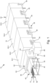
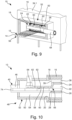
- the figures show an oven 10 for the thermal treatment of material, in which it is in the Figures 1 to 9
- the exemplary embodiments shown are fibers 12 and, for example, fibers 14 made of oxidized polyacrylonitrile, which are referred to below as oxPAN fibers 14.
- the oven 10 includes a thermally insulated oven housing 16, which delimits an interior 18.
- the furnace housing 16 has a fiber input passage 20 on one end face and a fiber output passage on an opposite end face, which cannot be seen in the figures due to the views shown.
- a process space housing 24 in the form of a muffle 26.
- the muffle 26 is made of graphite.
- the process chamber housing 24, ie the muffle 26, has a fiber inlet opening 28 on one end face and a fiber outlet opening on an opposite end face, which also cannot be seen in the figures.
- a process space atmosphere 30 prevails in the process space 22.
- the oven 10 includes a heating system 32 with which the process room atmosphere 28 is heated.
- successive heating zones 34 are formed in the process space 22 between the fiber inlet opening 22 and the fiber outlet opening of the muffle 26, of which those in Figure 1 five heating zones 34.1, 34.2, 34.3, 34.4 and 34.5 can be seen.
- the temperature increases from heating zone to heating zone in such a way that there is a temperature gradient of approximately 800° C. to approximately 1800° C. in the process space 22.
- Each heating zone 34 is assigned a separate heating device 36, which heats the muffle 26 in the associated heating zone 34 accordingly, as is known per se.
- the muffle 26 in each heating zone 34 is surrounded, for example, by a heating cage, not specifically shown, which is arranged in the space between the muffle 26 and the furnace housing 16. This space defines a heating space 38 surrounding the muffle 26.
- the heating chamber 38 is delimited at the front by insulation 39, which is only indicated schematically by a line.
- An inert gas atmosphere prevails in the heating room 38, for which purpose it is fed with an inert gas by means of an inert gas device not specifically shown;
- nitrogen N 2 is used as an inert gas for the heating room 38.
- the furnace 10 includes an input lock 40 with a separate lock housing 42 and, again based on the views shown Unrecognizable exit lock with a separate lock housing.
- an inert gas 46 is supplied to the interior 18 of the furnace housing 16, and thereby to the heating room 38 and the process room 22, with the aid of an inert gas device 44, so that the thermal treatment of the oxPAN fibers 14 takes place under an inert gas atmosphere.
- nitrogen N 2 or argon Ar are used as inert gas in practice.
- the process room atmosphere 30 is therefore a mixture of the inert gas and the pyrolysis gas released during the treatment of the oxPAN fibers 14.
- the oven 10 also includes a extraction system, designated overall by 48, by means of which the process room atmosphere 30 can be extracted from the process room 22.
- a passage housing 50 of a suction device 52 of the extraction system 48 is arranged between the entrance lock 40 and the furnace housing 16, which delimits a flow space 54.
- This flow space 54 is connected in a gas-tight manner to the input lock 40 on one side and to the furnace housing 16 in a gas-tight manner on the other side, so that the inert gas 46 can flow from the input lock 40 through the flow space 54 into the process space 22.
- the oxPAN fibers 14 are conveyed as a fiber carpet 56 through the entrance lock 40, through the flow space 54 and further through the fiber entrance passage 20 of the furnace housing 16 into its interior 18 and there through the using a conveyor system not specifically shown, which is known per se Fiber inlet opening 26 of the process space housing 24 is guided into the process space 22.
- the fiber carpet 56 passes through the process space 22 and the heating zones 34 established there and is then passed through the fiber outlet opening of the process space housing 24 and led out of the oven 10 through the fiber exit passage of the oven housing 16 and finally through the associated exit lock.
- the suction device comprises at least one suction channel 60 delimited by a channel wall 58, which is connected to the process room 22 via a suction opening 62.
- there are two such suction channels 60 which have the same reference numbers; In principle, a single suction channel 60 can be sufficient.
- the suction channels 60 are made of graphite or lined with graphite.
- additional suction openings 63 are provided in the channel wall 58 on the side facing the fiber carpet 56 as a variant; In most cases, however, these suction openings 63 can be dispensed with.
- the suction channels 60 have the suction opening 62 at a free end and are connected at their end remote from the suction opening 62 in the flow space 54 of the suction device 52 to a collecting channel 64, which extends outwards on both sides through the passage housing 50 and there leads to a thermal afterburning device 66.
- the collecting channel 64 is also made of graphite or lined with graphite.
- the suction channels 60 extend from the flow space 54 of the suction device 52 through the fiber inlet passage 20 of the furnace housing 16 and through the fiber inlet opening 28 of the muffle 26 into the process space 22, the suction channels 60 being arranged above the fiber carpet 56.
- the suction openings 62 of the suction channels 60 are located in this way in the process space 22, being positioned in an area 68 of the process space 22, which defines an inert suction area and in which there is a temperature at which there is no or at least only too a moderate chemical reaction between the pyrolysis gas in the process room atmosphere 30 and the muffle 26 and the suction channels 60 comes.
- a chemical reaction of the pyrolysis gas with the collecting channel 64 and the other lines, not shown, of the extraction system 48 is then prevented or reduced.
- the temperature in the area 68 must not be greater than approximately 1000 ° C, since the undesirable chemical reactions between graphite and the pyrolysis gas take place at this temperature.
- the area 68 has a temperature of less than 900 ° C, preferably less than 800 ° C.
- the area 68 is usually located directly next to the fiber inlet opening 28 of the process space 22.
- the position of the area 68 defined by the temperature prevailing there within the process space 22 can also change or the length of this area can change, depending on the set temperature profile in the process space 22. For this reason the suction channels 60 are set up in such a way that the position of the Suction opening 62 can be changed.
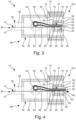
- the suction channels 60 are assembled in an end section 70 comprising the suction opening 62 from channel sections 72, which are detachably connected to one another, so that the length of the suction channels 60 can be adjusted by the number of channel sections 72 provided.
- Figure 3 an end section 70 made up of three channel sections 72 is shown.
- Figure 4 shows a suction channel 60, the end section 70 of which is formed from four channel sections 72, so that the suction opening 62 is compared to Figure 3 is arranged further away from the fiber inlet opening 28 and further inside the process space 22.
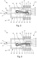
- Figure 5 shows a suction channel 60, the end section 70 of which is formed from only two channel sections 72, so that the suction opening 62 is compared to the Figures 3 and 4 is arranged closer to the fiber inlet opening 28 and therefore less far inside the process space 22.
- the end of these channel sections 72 therefore defines the suction opening 62 of the suction channel 60. If the additional suction openings 63 are provided, these are correspondingly present in the channel sections 72.
- the suction channels 60 can also be designed to be variable in shape, so that the position of the suction opening 62 can be shifted by varying the course of the suction channels 60 and these can be brought into an arc shape, for example.
- Figure 6 shows a modified suction device 52, in which the suction channels 60 are arranged below the fiber carpet 56. Otherwise this applies What was said above applies accordingly.
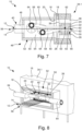
- Figure 7 shows a further modified suction device 52.
- a suction channel 52 runs above and a suction channel 52 below the fiber carpet 56.
- the suction channels 52 do not have a suction opening at their free end, but rather several lateral suction openings 62, including laterally on the flanks and / or Suction openings 62 provided in the channel wall 58 on the side facing the fiber carpet 56 are to be understood.
- a suction opening at the free end of the suction channels 60 is provided if the length of the suction channels 60 can be changed by corresponding channel sections 70, as in the previous exemplary embodiments.
- the channel sections 70 can then have corresponding lateral suction openings 62 in the channel wall 58.
- FIG 8 illustrates a variant in which each of the two suction channels 60 is connected to its own collection channel 64, each of which leads to its own thermal afterburning device, which is in Figure 8 are not shown separately again.
- Figure 9 illustrates a variant in which both existing suction channels 60 are again connected to a common collecting channel 64; However, this only extends on one side through the passage housing 50 of the suction device 52.
- FIG 10 a modification of an oven 10 is shown, which is not designed for the thermal treatment of fibers 12, but for the thermal treatment of plate-shaped materials 74, during its thermal treatment Pyrolysis gas is released.
- Such materials include, for example, hard felts.
- continuous materials such as fleeces and soft felts in rolls can also be classified as plate-shaped materials.
- This plate-shaped material 74 is conveyed through the process space 22 via a conveyor device not specifically shown, which can be, for example, a push system.
- a conveyor device not specifically shown, which can be, for example, a push system.
- the suction channels 60 of which only one can be seen due to the cut, run above the material 74 and again have lateral suction openings on the flanks and the side of the channel wall 58 facing the material 74.
- the collecting channel 64 also does not extend to the side, but rather upwards through the passage housing 50 of the suction device 52.
- the suction channels 60 can also be designed with protective plates made of silicon carbide SiC. If temperatures do arise at the suction opening 62 at which a chemical reaction of the pyrolysis gas with the muffle 26 or the suction channels 60 can occur, the SiC is chemically reduced, with the muffle 26 remaining protected.
Landscapes
- Engineering & Computer Science (AREA)
- Mechanical Engineering (AREA)
- General Engineering & Computer Science (AREA)
- Chemical & Material Sciences (AREA)
- Textile Engineering (AREA)
- Chemical Kinetics & Catalysis (AREA)
- General Chemical & Material Sciences (AREA)
- Environmental & Geological Engineering (AREA)
- Manufacturing & Machinery (AREA)
- Combustion & Propulsion (AREA)
- Inorganic Fibers (AREA)
- Furnace Details (AREA)
- Devices That Are Associated With Refrigeration Equipment (AREA)
- Tunnel Furnaces (AREA)
Claims (8)
- Four pour le traitement thermique, notamment pour la carbonisation et/ou graphitisation, de fibres (12), notamment de fibres (14) en polyacrylonitrile PAN oxydé, dans lequel un gaz de pyrolyse est libéré des fibres (12) lors du traitement thermique, aveca) un logement (16) ;b) un espace de processus (22) se trouvant dans l'espace interne (18) du logement (16) qui est limité par un logement d'espace de processus (24) et à travers lequel les fibres (12) peuvent être guidées, dans lequel le logement d'espace de processus (24) a sur un côté frontal une ouverture d'entrée de fibre (28) et sur un côté frontal opposé une ouverture de sortie de fibre ;c) un système de chauffage (32) au moyen duquel une atmosphère d'espace de processus (30) régnant dans l'espace de processus (22) peut être chauffée, dans lequel des zones de chauffage successives (34) sont formées par le système de chauffage (32) dans l'espace de processus (22) entre l'ouverture d'entrée de fibre (28) et l'ouverture de sortie de fibre ;d) un système de prélèvement (48) au moyen duquel l'atmosphère d'espace de processus (30) chargée de gaz de pyrolyse peut être aspirée de l'espace de processus (22),caractérisé en ce quee) le système de prélèvement (48) présente au moins un dispositif d'aspiration (52) avec un canal d'aspiration (60) limité par une paroi de canal (58) qui est connecté à l'espace de processus (22) par le biais d'une ouverture d'aspiration (62) ;f) l'ouverture d'aspiration (62) est disposée dans une région (68) de l'espace de processus (22) qui est la première zone de chauffage (34.1) en partant de l'ouverture d'entrée de fibre (28) et dans laquelle une température règne lors du fonctionnement du four (10), à laquelle il ne se produit aucune ou que des réactions chimiques modérées entre le gaz de pyrolyse et le logement d'espace de processus (24) et/ou la paroi de canal (58) ;dans lequel
g) une température de moins de 1000 °C, de préférence de moins de 900°C et de manière particulièrement préférée de moins de 800 °C règne dans cette région (68) lors du fonctionnement du four (10). - Four selon la revendication 1, caractérisé en ce que le canal d'aspiration (60) s'étend à travers l'ouverture d'entrée (28) dans l'espace de processus (22).
- Four selon une des revendications précédentes, caractérisé en ce que le canal d'aspiration (60) est configuré de telle sorte que la position de l'ouverture d'aspiration (62) peut être modifiée.
- Four selon la revendication 3, caractérisé en ce que le canal d'aspiration (60) comprend plusieurs sections de canal (72) qui sont connectées l'une à l'autre de manière amovible de telle sorte que la longueur du canal d'aspiration (60) peut être réglée par le nombre des sections de canal prévues (72).
- Four selon une des revendications 1 à 4, caractérisé en ce que le canal d'aspiration (60) est connecté à une extrémité éloignée de l'ouverture d'aspiration (62) à un canal collecteur (64) qui est connecté de son côté à un dispositif de postcombustion thermique (66).
- Four selon la revendication 5, caractérisé en ce qu'une enceinte de passage (50) du dispositif d'aspiration (52) dans laquelle le canal collecteur (64) s'étend au moins par régions est disposée avant un passage d'entrée (20) du logement (16).
- Four selon une des revendications 1 à 6, caractérisé en ce que le logement d'espace de processus (24) est réalisé en tant que moufle (26), notamment en tant que moufle (26) en graphite.
- Four selon une des revendications 1 à 7, caractérisé en ce que le canal d'aspiration (60) et/ou le canal collecteur (64) sont réalisés en graphite ou recouverts de graphite.
Applications Claiming Priority (2)
| Application Number | Priority Date | Filing Date | Title |
|---|---|---|---|
| DE102017113342.9A DE102017113342A1 (de) | 2017-06-19 | 2017-06-19 | Ofen |
| PCT/EP2018/065716 WO2018234126A1 (fr) | 2017-06-19 | 2018-06-13 | Four |
Publications (2)
| Publication Number | Publication Date |
|---|---|
| EP3735564A1 EP3735564A1 (fr) | 2020-11-11 |
| EP3735564B1 true EP3735564B1 (fr) | 2023-10-04 |
Family
ID=62599631
Family Applications (1)
| Application Number | Title | Priority Date | Filing Date |
|---|---|---|---|
| EP18731090.9A Active EP3735564B1 (fr) | 2017-06-19 | 2018-06-13 | Four |
Country Status (7)
| Country | Link |
|---|---|
| US (1) | US11603607B2 (fr) |
| EP (1) | EP3735564B1 (fr) |
| KR (1) | KR102552048B1 (fr) |
| CN (1) | CN110799797B (fr) |
| DE (1) | DE102017113342A1 (fr) |
| ES (1) | ES2967442T3 (fr) |
| WO (1) | WO2018234126A1 (fr) |
Families Citing this family (6)
| Publication number | Priority date | Publication date | Assignee | Title |
|---|---|---|---|---|
| DE102014009243B3 (de) | 2014-06-20 | 2015-11-19 | Eisenmann Ag | Oxidationsofen |
| DE102014009244B4 (de) | 2014-06-20 | 2016-07-28 | Eisenmann Se | Oxidationsofen |
| DE102016116057A1 (de) | 2016-08-29 | 2018-03-15 | Eisenmann Se | Oxidationsofen |
| DE102018108291A1 (de) * | 2018-04-09 | 2019-10-10 | Eisenmann Se | Ofen |
| CN113718228A (zh) * | 2020-05-26 | 2021-11-30 | 浙江上方电子装备有限公司 | 基材镀膜系统 |
| DE102022118108A1 (de) * | 2022-07-20 | 2024-01-25 | Onejoon Gmbh | Vorrichtung zum thermischen oder thermo-chemischen Behandeln von Material |
Family Cites Families (11)
| Publication number | Priority date | Publication date | Assignee | Title |
|---|---|---|---|---|
| FR2534240A1 (fr) * | 1982-10-06 | 1984-04-13 | Savoie Electrodes Refract | Procede continu de graphitisation de produits carbones longs et four pour la mise en oeuvre de ce procede |
| JPS6013950A (ja) | 1983-07-04 | 1985-01-24 | Toyota Motor Corp | 燃料噴射時期制御方法 |
| US4659356A (en) | 1985-11-12 | 1987-04-21 | Ppg Industries, Inc. | Kiln construction |
| US4678433A (en) * | 1985-12-30 | 1987-07-07 | Hunter Engineering (Canada) Ltd. | Oven system having a heated snout at its entrance end |
| KR890002459A (ko) * | 1987-07-31 | 1989-04-10 | 오카다 모리오 | 내염화섬유의 제조방법 |
| JPH07118933A (ja) * | 1991-05-28 | 1995-05-09 | Toho Rayon Co Ltd | 炭素繊維連続焼成炉のシール方法 |
| JP2000088464A (ja) * | 1998-09-08 | 2000-03-31 | Toray Ind Inc | 熱処理炉およびそれを用いた炭素繊維の製造方法 |
| JP2010133059A (ja) | 2008-12-05 | 2010-06-17 | Mitsubishi Rayon Co Ltd | 耐炎化炉及びこれを用いた炭素繊維の製造方法 |
| DE102010044296B3 (de) | 2010-09-03 | 2012-01-05 | Eisenmann Ag | Oxidationsofen |
| KR101604932B1 (ko) | 2011-07-28 | 2016-03-18 | 미쯔비시 레이온 가부시끼가이샤 | 내염화 열처리로 |
| JP5778363B1 (ja) | 2015-01-21 | 2015-09-16 | Secカーボン株式会社 | 熱処理装置 |
-
2017
- 2017-06-19 DE DE102017113342.9A patent/DE102017113342A1/de active Pending
-
2018
- 2018-06-13 WO PCT/EP2018/065716 patent/WO2018234126A1/fr not_active Ceased
- 2018-06-13 CN CN201880040545.1A patent/CN110799797B/zh active Active
- 2018-06-13 EP EP18731090.9A patent/EP3735564B1/fr active Active
- 2018-06-13 ES ES18731090T patent/ES2967442T3/es active Active
- 2018-06-13 KR KR1020197037603A patent/KR102552048B1/ko active Active
- 2018-06-13 US US16/623,469 patent/US11603607B2/en active Active
Also Published As
| Publication number | Publication date |
|---|---|
| US11603607B2 (en) | 2023-03-14 |
| US20200181809A1 (en) | 2020-06-11 |
| CN110799797B (zh) | 2023-03-31 |
| DE102017113342A1 (de) | 2018-12-20 |
| EP3735564A1 (fr) | 2020-11-11 |
| ES2967442T3 (es) | 2024-04-30 |
| WO2018234126A1 (fr) | 2018-12-27 |
| CN110799797A (zh) | 2020-02-14 |
| KR20200019883A (ko) | 2020-02-25 |
| KR102552048B1 (ko) | 2023-07-05 |
Similar Documents
| Publication | Publication Date | Title |
|---|---|---|
| EP3735564B1 (fr) | Four | |
| DE69603593T2 (de) | Verfahren zur chemischen infiltration in der gasphase, zur verdichtung poröser rotationssymmetrischer substratstapeln | |
| DE102009038598B4 (de) | Verfahren und Vorrichtung zur Aufbereitung von Prozessgasen für Wärmebehandlungen von metallischen Werkstoffen/Werkstücken in Industrieöfen | |
| EP0743381B1 (fr) | Procédé pour stabiliser thermiquement des produits multicouches à base de fibres de polyacrylonitrile | |
| DE2362132A1 (de) | Einrichtung zur thermischen behandlung von feinkoernigem gut mit mehreren einem waermetauschersystem zugeordneten zusatzbrenneinrichtungen | |
| DE3819883A1 (de) | Verfahren und vorrichtung zur behandlung von mit honigtau befallene baumwolle | |
| EP3158116A1 (fr) | Four d'oxydation | |
| DE3435120A1 (de) | Verfahren zur veredelung kohlenstoffhaltiger zwischenfasern | |
| DE2529740A1 (de) | Automatisch arbeitende anlage zum trocknen und zum schnellen einphasen- brennen keramischer ziegelkoerper | |
| DE60313177T2 (de) | Verfahren und vorrichtung zur herstellung von kohlenstoffprodukten aus kohlenstoffvorläuferprodukten | |
| EP3775339B1 (fr) | Four | |
| EP3762526B1 (fr) | Procédé et dispositif de stabilisation de fibres précurseurs pour la fabrication de fibres de carbone | |
| DE2231731A1 (de) | Verfahren und vorrichtung zur herstellung von kohlefasern | |
| EP1581677B1 (fr) | Dispositif de chauffage destine a chauffer un fil | |
| DE102015112375A1 (de) | Durchlaufofen und Verfahren zu dessen Betrieb | |
| EP1898170A2 (fr) | Dispositif destiné au traitement chimique et/ou physique de pièces | |
| DE19538364C5 (de) | Vorrichtung zur Schnellerwärmung von Metall-Preßbolzen | |
| EP0093877A2 (fr) | Dispositif pour le traitement thermique de pièces de matière à haute température | |
| DE3413472A1 (de) | Verfahren zum einfuehren einer langen waermeempfindlichen materialbahn unter spannung in einen ofen | |
| DE102010035569A1 (de) | Durchlaufofen | |
| DE102005053134A1 (de) | Anlage zur trockenen Umwandlung eines Material-Gefüges von Halbzeugen | |
| EP2856498B1 (fr) | Suscepteur | |
| DE602005005343T2 (de) | Vorrichtung zur thermomechanischen behandlung bei niedrigem druck | |
| DE3521411A1 (de) | Verfahren und tunnelofen zum brennen von kohlenstoffhaltigen oder graphithaltigen formkoerpern | |
| AT523094B1 (de) | Sinterofen |
Legal Events
| Date | Code | Title | Description |
|---|---|---|---|
| STAA | Information on the status of an ep patent application or granted ep patent |
Free format text: STATUS: UNKNOWN |
|
| STAA | Information on the status of an ep patent application or granted ep patent |
Free format text: STATUS: THE INTERNATIONAL PUBLICATION HAS BEEN MADE |
|
| PUAI | Public reference made under article 153(3) epc to a published international application that has entered the european phase |
Free format text: ORIGINAL CODE: 0009012 |
|
| STAA | Information on the status of an ep patent application or granted ep patent |
Free format text: STATUS: REQUEST FOR EXAMINATION WAS MADE |
|
| 17P | Request for examination filed |
Effective date: 20191204 |
|
| AK | Designated contracting states |
Kind code of ref document: A1 Designated state(s): AL AT BE BG CH CY CZ DE DK EE ES FI FR GB GR HR HU IE IS IT LI LT LU LV MC MK MT NL NO PL PT RO RS SE SI SK SM TR |
|
| AX | Request for extension of the european patent |
Extension state: BA ME |
|
| STAA | Information on the status of an ep patent application or granted ep patent |
Free format text: STATUS: EXAMINATION IS IN PROGRESS |
|
| 17Q | First examination report despatched |
Effective date: 20210927 |
|
| GRAP | Despatch of communication of intention to grant a patent |
Free format text: ORIGINAL CODE: EPIDOSNIGR1 |
|
| STAA | Information on the status of an ep patent application or granted ep patent |
Free format text: STATUS: GRANT OF PATENT IS INTENDED |
|
| DAV | Request for validation of the european patent (deleted) | ||
| DAX | Request for extension of the european patent (deleted) | ||
| INTG | Intention to grant announced |
Effective date: 20230517 |
|
| RIN1 | Information on inventor provided before grant (corrected) |
Inventor name: SABELFELD, DIMITRI Inventor name: MUCK, MATTHIAS |
|
| GRAS | Grant fee paid |
Free format text: ORIGINAL CODE: EPIDOSNIGR3 |
|
| GRAA | (expected) grant |
Free format text: ORIGINAL CODE: 0009210 |
|
| STAA | Information on the status of an ep patent application or granted ep patent |
Free format text: STATUS: THE PATENT HAS BEEN GRANTED |
|
| AK | Designated contracting states |
Kind code of ref document: B1 Designated state(s): AL AT BE BG CH CY CZ DE DK EE ES FI FR GB GR HR HU IE IS IT LI LT LU LV MC MK MT NL NO PL PT RO RS SE SI SK SM TR |
|
| REG | Reference to a national code |
Ref country code: GB Ref legal event code: FG4D Free format text: NOT ENGLISH |
|
| REG | Reference to a national code |
Ref country code: CH Ref legal event code: EP |
|
| REG | Reference to a national code |
Ref country code: IE Ref legal event code: FG4D Free format text: LANGUAGE OF EP DOCUMENT: GERMAN |
|
| REG | Reference to a national code |
Ref country code: DE Ref legal event code: R096 Ref document number: 502018013387 Country of ref document: DE |
|
| P01 | Opt-out of the competence of the unified patent court (upc) registered |
Effective date: 20230927 |
|
| REG | Reference to a national code |
Ref country code: LT Ref legal event code: MG9D |
|
| REG | Reference to a national code |
Ref country code: NL Ref legal event code: MP Effective date: 20231004 |
|
| PG25 | Lapsed in a contracting state [announced via postgrant information from national office to epo] |
Ref country code: NL Free format text: LAPSE BECAUSE OF FAILURE TO SUBMIT A TRANSLATION OF THE DESCRIPTION OR TO PAY THE FEE WITHIN THE PRESCRIBED TIME-LIMIT Effective date: 20231004 |
|
| PG25 | Lapsed in a contracting state [announced via postgrant information from national office to epo] |
Ref country code: GR Free format text: LAPSE BECAUSE OF FAILURE TO SUBMIT A TRANSLATION OF THE DESCRIPTION OR TO PAY THE FEE WITHIN THE PRESCRIBED TIME-LIMIT Effective date: 20240105 |
|
| PG25 | Lapsed in a contracting state [announced via postgrant information from national office to epo] |
Ref country code: IS Free format text: LAPSE BECAUSE OF FAILURE TO SUBMIT A TRANSLATION OF THE DESCRIPTION OR TO PAY THE FEE WITHIN THE PRESCRIBED TIME-LIMIT Effective date: 20240204 |
|
| PG25 | Lapsed in a contracting state [announced via postgrant information from national office to epo] |
Ref country code: LT Free format text: LAPSE BECAUSE OF FAILURE TO SUBMIT A TRANSLATION OF THE DESCRIPTION OR TO PAY THE FEE WITHIN THE PRESCRIBED TIME-LIMIT Effective date: 20231004 |
|
| PG25 | Lapsed in a contracting state [announced via postgrant information from national office to epo] |
Ref country code: LT Free format text: LAPSE BECAUSE OF FAILURE TO SUBMIT A TRANSLATION OF THE DESCRIPTION OR TO PAY THE FEE WITHIN THE PRESCRIBED TIME-LIMIT Effective date: 20231004 Ref country code: IS Free format text: LAPSE BECAUSE OF FAILURE TO SUBMIT A TRANSLATION OF THE DESCRIPTION OR TO PAY THE FEE WITHIN THE PRESCRIBED TIME-LIMIT Effective date: 20240204 Ref country code: GR Free format text: LAPSE BECAUSE OF FAILURE TO SUBMIT A TRANSLATION OF THE DESCRIPTION OR TO PAY THE FEE WITHIN THE PRESCRIBED TIME-LIMIT Effective date: 20240105 Ref country code: BG Free format text: LAPSE BECAUSE OF FAILURE TO SUBMIT A TRANSLATION OF THE DESCRIPTION OR TO PAY THE FEE WITHIN THE PRESCRIBED TIME-LIMIT Effective date: 20240104 Ref country code: PT Free format text: LAPSE BECAUSE OF FAILURE TO SUBMIT A TRANSLATION OF THE DESCRIPTION OR TO PAY THE FEE WITHIN THE PRESCRIBED TIME-LIMIT Effective date: 20240205 |
|
| REG | Reference to a national code |
Ref country code: ES Ref legal event code: FG2A Ref document number: 2967442 Country of ref document: ES Kind code of ref document: T3 Effective date: 20240430 |
|
| PG25 | Lapsed in a contracting state [announced via postgrant information from national office to epo] |
Ref country code: SE Free format text: LAPSE BECAUSE OF FAILURE TO SUBMIT A TRANSLATION OF THE DESCRIPTION OR TO PAY THE FEE WITHIN THE PRESCRIBED TIME-LIMIT Effective date: 20231004 Ref country code: RS Free format text: LAPSE BECAUSE OF FAILURE TO SUBMIT A TRANSLATION OF THE DESCRIPTION OR TO PAY THE FEE WITHIN THE PRESCRIBED TIME-LIMIT Effective date: 20231004 Ref country code: PL Free format text: LAPSE BECAUSE OF FAILURE TO SUBMIT A TRANSLATION OF THE DESCRIPTION OR TO PAY THE FEE WITHIN THE PRESCRIBED TIME-LIMIT Effective date: 20231004 Ref country code: NO Free format text: LAPSE BECAUSE OF FAILURE TO SUBMIT A TRANSLATION OF THE DESCRIPTION OR TO PAY THE FEE WITHIN THE PRESCRIBED TIME-LIMIT Effective date: 20240104 Ref country code: LV Free format text: LAPSE BECAUSE OF FAILURE TO SUBMIT A TRANSLATION OF THE DESCRIPTION OR TO PAY THE FEE WITHIN THE PRESCRIBED TIME-LIMIT Effective date: 20231004 Ref country code: HR Free format text: LAPSE BECAUSE OF FAILURE TO SUBMIT A TRANSLATION OF THE DESCRIPTION OR TO PAY THE FEE WITHIN THE PRESCRIBED TIME-LIMIT Effective date: 20231004 |
|
| REG | Reference to a national code |
Ref country code: DE Ref legal event code: R097 Ref document number: 502018013387 Country of ref document: DE |
|
| PG25 | Lapsed in a contracting state [announced via postgrant information from national office to epo] |
Ref country code: DK Free format text: LAPSE BECAUSE OF FAILURE TO SUBMIT A TRANSLATION OF THE DESCRIPTION OR TO PAY THE FEE WITHIN THE PRESCRIBED TIME-LIMIT Effective date: 20231004 |
|
| PG25 | Lapsed in a contracting state [announced via postgrant information from national office to epo] |
Ref country code: CZ Free format text: LAPSE BECAUSE OF FAILURE TO SUBMIT A TRANSLATION OF THE DESCRIPTION OR TO PAY THE FEE WITHIN THE PRESCRIBED TIME-LIMIT Effective date: 20231004 |
|
| PG25 | Lapsed in a contracting state [announced via postgrant information from national office to epo] |
Ref country code: SK Free format text: LAPSE BECAUSE OF FAILURE TO SUBMIT A TRANSLATION OF THE DESCRIPTION OR TO PAY THE FEE WITHIN THE PRESCRIBED TIME-LIMIT Effective date: 20231004 |
|
| PG25 | Lapsed in a contracting state [announced via postgrant information from national office to epo] |
Ref country code: SM Free format text: LAPSE BECAUSE OF FAILURE TO SUBMIT A TRANSLATION OF THE DESCRIPTION OR TO PAY THE FEE WITHIN THE PRESCRIBED TIME-LIMIT Effective date: 20231004 Ref country code: SK Free format text: LAPSE BECAUSE OF FAILURE TO SUBMIT A TRANSLATION OF THE DESCRIPTION OR TO PAY THE FEE WITHIN THE PRESCRIBED TIME-LIMIT Effective date: 20231004 Ref country code: RO Free format text: LAPSE BECAUSE OF FAILURE TO SUBMIT A TRANSLATION OF THE DESCRIPTION OR TO PAY THE FEE WITHIN THE PRESCRIBED TIME-LIMIT Effective date: 20231004 Ref country code: IT Free format text: LAPSE BECAUSE OF FAILURE TO SUBMIT A TRANSLATION OF THE DESCRIPTION OR TO PAY THE FEE WITHIN THE PRESCRIBED TIME-LIMIT Effective date: 20231004 Ref country code: EE Free format text: LAPSE BECAUSE OF FAILURE TO SUBMIT A TRANSLATION OF THE DESCRIPTION OR TO PAY THE FEE WITHIN THE PRESCRIBED TIME-LIMIT Effective date: 20231004 Ref country code: DK Free format text: LAPSE BECAUSE OF FAILURE TO SUBMIT A TRANSLATION OF THE DESCRIPTION OR TO PAY THE FEE WITHIN THE PRESCRIBED TIME-LIMIT Effective date: 20231004 Ref country code: CZ Free format text: LAPSE BECAUSE OF FAILURE TO SUBMIT A TRANSLATION OF THE DESCRIPTION OR TO PAY THE FEE WITHIN THE PRESCRIBED TIME-LIMIT Effective date: 20231004 |
|
| PLBE | No opposition filed within time limit |
Free format text: ORIGINAL CODE: 0009261 |
|
| STAA | Information on the status of an ep patent application or granted ep patent |
Free format text: STATUS: NO OPPOSITION FILED WITHIN TIME LIMIT |
|
| 26N | No opposition filed |
Effective date: 20240705 |
|
| PG25 | Lapsed in a contracting state [announced via postgrant information from national office to epo] |
Ref country code: SI Free format text: LAPSE BECAUSE OF FAILURE TO SUBMIT A TRANSLATION OF THE DESCRIPTION OR TO PAY THE FEE WITHIN THE PRESCRIBED TIME-LIMIT Effective date: 20231004 |
|
| PG25 | Lapsed in a contracting state [announced via postgrant information from national office to epo] |
Ref country code: SI Free format text: LAPSE BECAUSE OF FAILURE TO SUBMIT A TRANSLATION OF THE DESCRIPTION OR TO PAY THE FEE WITHIN THE PRESCRIBED TIME-LIMIT Effective date: 20231004 |
|
| PG25 | Lapsed in a contracting state [announced via postgrant information from national office to epo] |
Ref country code: MC Free format text: LAPSE BECAUSE OF FAILURE TO SUBMIT A TRANSLATION OF THE DESCRIPTION OR TO PAY THE FEE WITHIN THE PRESCRIBED TIME-LIMIT Effective date: 20231004 |
|
| REG | Reference to a national code |
Ref country code: CH Ref legal event code: PL |
|
| PG25 | Lapsed in a contracting state [announced via postgrant information from national office to epo] |
Ref country code: LU Free format text: LAPSE BECAUSE OF NON-PAYMENT OF DUE FEES Effective date: 20240613 |
|
| PG25 | Lapsed in a contracting state [announced via postgrant information from national office to epo] |
Ref country code: IE Free format text: LAPSE BECAUSE OF NON-PAYMENT OF DUE FEES Effective date: 20240613 |
|
| PG25 | Lapsed in a contracting state [announced via postgrant information from national office to epo] |
Ref country code: BE Free format text: LAPSE BECAUSE OF NON-PAYMENT OF DUE FEES Effective date: 20240630 Ref country code: CH Free format text: LAPSE BECAUSE OF NON-PAYMENT OF DUE FEES Effective date: 20240630 |
|
| REG | Reference to a national code |
Ref country code: BE Ref legal event code: MM Effective date: 20240630 |
|
| PGFP | Annual fee paid to national office [announced via postgrant information from national office to epo] |
Ref country code: DE Payment date: 20250618 Year of fee payment: 8 |
|
| PGFP | Annual fee paid to national office [announced via postgrant information from national office to epo] |
Ref country code: GB Payment date: 20250620 Year of fee payment: 8 |
|
| PGFP | Annual fee paid to national office [announced via postgrant information from national office to epo] |
Ref country code: FR Payment date: 20250624 Year of fee payment: 8 |
|
| PGFP | Annual fee paid to national office [announced via postgrant information from national office to epo] |
Ref country code: TR Payment date: 20250611 Year of fee payment: 8 |
|
| REG | Reference to a national code |
Ref country code: AT Ref legal event code: MM01 Ref document number: 1618126 Country of ref document: AT Kind code of ref document: T Effective date: 20240613 |
|
| PG25 | Lapsed in a contracting state [announced via postgrant information from national office to epo] |
Ref country code: FI Free format text: LAPSE BECAUSE OF FAILURE TO SUBMIT A TRANSLATION OF THE DESCRIPTION OR TO PAY THE FEE WITHIN THE PRESCRIBED TIME-LIMIT Effective date: 20231004 |
|
| PGFP | Annual fee paid to national office [announced via postgrant information from national office to epo] |
Ref country code: ES Payment date: 20250718 Year of fee payment: 8 |
|
| PG25 | Lapsed in a contracting state [announced via postgrant information from national office to epo] |
Ref country code: AT Free format text: LAPSE BECAUSE OF NON-PAYMENT OF DUE FEES Effective date: 20240613 |
|
| PG25 | Lapsed in a contracting state [announced via postgrant information from national office to epo] |
Ref country code: CY Free format text: LAPSE BECAUSE OF FAILURE TO SUBMIT A TRANSLATION OF THE DESCRIPTION OR TO PAY THE FEE WITHIN THE PRESCRIBED TIME-LIMIT; INVALID AB INITIO Effective date: 20180613 |
|
| PG25 | Lapsed in a contracting state [announced via postgrant information from national office to epo] |
Ref country code: HU Free format text: LAPSE BECAUSE OF FAILURE TO SUBMIT A TRANSLATION OF THE DESCRIPTION OR TO PAY THE FEE WITHIN THE PRESCRIBED TIME-LIMIT; INVALID AB INITIO Effective date: 20180613 |