EP3735665B1 - Gestion de palettes de contenants de produits valorises - Google Patents
Gestion de palettes de contenants de produits valorises Download PDFInfo
- Publication number
- EP3735665B1 EP3735665B1 EP18815216.9A EP18815216A EP3735665B1 EP 3735665 B1 EP3735665 B1 EP 3735665B1 EP 18815216 A EP18815216 A EP 18815216A EP 3735665 B1 EP3735665 B1 EP 3735665B1
- Authority
- EP
- European Patent Office
- Prior art keywords
- pallet
- containers
- belt
- pallets
- management system
- Prior art date
- Legal status (The legal status is an assumption and is not a legal conclusion. Google has not performed a legal analysis and makes no representation as to the accuracy of the status listed.)
- Active
Links
Images







Classifications
-
- G—PHYSICS
- G06—COMPUTING OR CALCULATING; COUNTING
- G06Q—INFORMATION AND COMMUNICATION TECHNOLOGY [ICT] SPECIALLY ADAPTED FOR ADMINISTRATIVE, COMMERCIAL, FINANCIAL, MANAGERIAL OR SUPERVISORY PURPOSES; SYSTEMS OR METHODS SPECIALLY ADAPTED FOR ADMINISTRATIVE, COMMERCIAL, FINANCIAL, MANAGERIAL OR SUPERVISORY PURPOSES, NOT OTHERWISE PROVIDED FOR
- G06Q10/00—Administration; Management
- G06Q10/08—Logistics, e.g. warehousing, loading or distribution; Inventory or stock management
Definitions
- the invention relates in general to the production of rubber mixtures and of vehicle tyres produced therefrom. More particularly, the invention relates to the management of the loading and reloading of pallets with containers of recovered products as starter products in a mixing cycle.
- tyre manufacture there are a number of machines that produce semifinished products.
- the products produced by these machines are made up of at least two rubber mixtures having different properties (referred to as "complex products").
- the machines perform various processes, including extrusion processes, assembly processes and stripping processes, in which some of what is manufactured cannot be used directly in the creation of a tyre (for example, during a change in size, a start-up, etc.).
- start-ups, stoppages, changes in size and other known steps it is commonplace for these machines to generate products that are not used downstream (for example, on the assembly machines).
- the complex products that are not used “as is”, but that can be recovered for reuse after treatment are usually stored without any special consideration (for example, on pallets with dividers).
- recovered products for example, on pallets with dividers.
- the present invention relates to the management of pallets of containers of recovered products, including the loading, identification, storage and immobilization thereof, so that the recovered products can be used in rubber mixtures.
- numerous types of rubber mixtures are envisaged in the tyre production processes, there are at the same time opportunities for optimizing the availability of the pallets during management thereof.
- Patent document WO2008/021398A2 is a relevant background art that focuses on building mixed pallets based on order specifications and container characteristics.
- the invention relates to a management system for the management of pallets of containers of recovered products, retrieved from a system for the storage of recovered products, according to an ongoing campaign.
- the system includes:
- the belt (I) includes a provisioning zone in which the pallets of full containers enter a management system; a standby zone in which the pallets remain on standby during the ongoing campaign; and a standby-for-emptying zone in which the pallets remain on standby awaiting emptying.
- the belt (II) includes two discharge zones in which the pallets with full containers are transferred to the full-containers outlet so that they can be stored in the system for the storage of recovered products; and an emptying zone in which the containers from the pallet on standby are emptied.
- the belt (III) includes an empty-pallet provisioning/discharge zone in which the empty pallets enter and leave the management system; a pallet-standby zone in which pallets remain on standby awaiting empty containers; and a stacking zone in which the empty containers are stored on available pallets.
- the belt (IV) includes a discharge zone in which the pallets stocked with the empty containers leave the management system.
- the system further includes several containers designated for receiving the corresponding recovered products, each container having long sides, short sides and a bottom that together form a space to receive a corresponding recovered product, and a pair of legs that extend below the bottom, and/or top, so as to make the container stackable on a pallet or on itself.
- an interior surface of each long side and/or each short side is inclined with respect to the bottom in order to promote release of the recovered product from the full container.
- the inclination may be effected by an angle of up to 5°.
- the system further includes an identification and gripping means with an RFID tag, positioned on the container, that allows an RFID reader positioned on a gripper to identify the container.
- the identification and gripping means further includes a gripping system with a square recess and a triangular recess built into each short side of the container; and a square projection and a triangular projection on the gripper so that the gripping system allows the container to be suitably positioned by realigning a projection in a corresponding recess.
- the system further includes a container demoulding system.
- the demoulding system has a demoulding device with retractable fingers in register with orifices aligned along the length of the bottom of the container, such that the retractable fingers enter the container through the orifices and push the recovered product so as to empty the container.
- the system further includes several pallets previously identified as a function of the ongoing campaign, on which pallets the containers full of recovered products and the empty containers are stored during a pallet transfer management sequence, the transfer management sequence being obtained as a function of the ongoing campaign.
- each pallet used in the management system is capable of storing and transporting up to nine containers.
- pallets with containers full of recovered products originating from a storage system are fed into the management system.
- the system further includes an identification means for harmonizing the identification of a pallet with the identification of the containers stored on the identified pallet.
- FIG 1 depicts an exemplary management system (or "system") 100 that is a system for the management of pallets of containers of recovered products.
- the management system 100 is situated downstream of a complex-product manufacturing system (for example, at least one of an extrusion system, an assembly system, a stripping system and/or at least one equivalent system).
- a complex-product manufacturing system for example, at least one of an extrusion system, an assembly system, a stripping system and/or at least one equivalent system.
- the management system 100 feeds an internal mixer with recovered products. It is envisioned for the management system 100 to allow the production of rubber mixtures with diverse and varying properties as determined by the performance requirements of the resulting tyre. Thus, during a given mixing cycle, recovered products that have the properties required during the ongoing manufacturing cycle are easily located and supplied by the management system 100.
- the recovered products are stored in a system for the storage of recovered products (for example, an automated storage and retrieval system (ASRS) or equivalent), these products being considered to be able to be used during a tyre manufacturing cycle.
- the unused complex products are identified into various kinds and various grades, and each kind and each grade designates a specific complex product, the properties of which are known.
- each kind, grades, batches of complex product will be designated by the term "nature" of complex product.
- Each nature of complex product has specific properties that can be controlled in order to obtain the recovered products.
- the recovered products arrive at the management system 100 from the system for the storage of recovered products having already been designated, according to their nature, for reincorporation into a rubber mixture.
- Each recovered product is stored in a container, and each container holds only one recovered product at a time.
- Each of the recovered products is characterized by a unique identification (for example, using numerals, codes, RFID identifications, hypertext links or equivalent means) that allows an extrusion or mixing machine (or equivalent) to know the complex product that is in the process of being manufactured according to a predefined recipe.
- a container (or "bucket") 200 comes with a pair of long sides 202, a pair of short sides 204 and a bottom 206 that together form a space to receive a specific recovered product for reuse.
- Each container 200 includes a pair of legs 208 that extend from the bottom 206 so as to make the container stackable on a pallet or on itself.
- corresponding structure or an equivalent structure (such as one or more tabs) may be employed at least a portion of the perimeter of the top of the container 200. Such corresponding structure may be used along or in combination with the legs 208 to ensure stackable alignment among multiple containers 200.
- the interior surface 202a of each long side 202 is inclined with respect to the bottom 206 (for example, by an angle of up to 5°) in order to promote release of the recovered product from the full container.
- An optional non-stick coating may be applied to the interior surface 202a to make it easier for the complex product to be extracted from the corresponding container.
- each recovered product is placed in a corresponding container 200 that is designated to receive it.
- the container 200 and its contents are identified, known and managed by virtue of an identification means incorporated into the container 200.
- Identification of the container 200 is performed either manually (for example, using at least one visual and/or tactile identifier) or automatically (for example using numerals, codes, RFID identifications, hypertext links or equivalent means).
- the invention is described in relation to an RFID identification incorporated into the container 200, but it is understood that other equivalent means of identification can be used.
- Identification of the recovered product is harmonized with the identification of the container so that the management system 100, by recognising a particular container, automatically recognises the nature of the recovered product inside the container.
- the containers 200 with the recovered products are identified and stored as a function of characteristics such as their nature.
- the filling of the container 200 is performed in such a way that its volume is generally constant.
- the management system 100 is therefore capable of transferring and of storing each container 200 according to its identification.
- the bottom 206 of the container 200 includes several orifices 206a aligned along the length of the bottom 206.
- a demoulding device 300 includes retractable fingers 302 in register with the orifices 206a of the container 200 (see Figure 4 ). The demoulding device 300 and the container 200 create a container-demoulding system of the management system 100. During a demoulding process, the retractable fingers 302 enter the container 200 through the orifices 206a (see arrow A in Figure 4 ) to push the recovered product (which is represented as P in Figures 4 and 5 ) and empty the container.
- the emptying of containers in the context of an exemplary method is described hereinafter.
- each short side 204 of the container 200 includes an identification and gripping means that works together with an automated handling device.
- the automated handling device is a gripper 400 (see Figure 6 ).
- the identification and gripping means includes an RFID tag 210, positioned on the container 200, that allows an RFID reader 410 positioned on the gripper 400 to identify the container 200.
- the identification and gripping means also includes a gripping system having a system of corresponding recesses and projections so that the gripping system allows the container 200 to be suitably positioned by realigning a projection in a corresponding recess.
- the recesses include a square recess 212 and a triangular recess 214 built into each short side 204 of the container 200.
- the projections include a square projection 412 and a triangular projection 414 on the gripper 400. It is understood that the geometry of the recesses and of the projections is not restricted to squares and triangles.
- this figure depicts a schematic view of the triangular projection 414 of the gripper 400 in a working position inside the triangular recess 214 of the container 200. If the triangular projection 414 is not aligned with the triangular recess 214, the triangular projection is still guided towards a position of alignment with the triangular recess 214.
- the system of recesses and of projections allows the container 200 to be suitably positioned by the realigning of the projection in the corresponding recess.
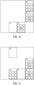
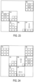
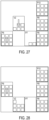
- each pallet used in the management system 100 is capable of storing and transporting up to nine containers 200 (full or empty) (see Figures 8 to 22 ). In the case of pallets completely filled with containers (full or empty)(or "complete pallets"), and also in the case of pallets that are not completely full of containers (or "incomplete pallets"), it is necessary to ensure suitable positioning of each container on the relevant pallet.
- the legs 208 of the container 200 enable stacking of the container on a pallet or on itself, and the identification and gripping means of the container 200 ensures suitable positioning (for example, ensuring vertical and horizontal alignment of containers with respect to one another and of containers with respect to the pallets).
- the management system 100 makes it possible to carry out a method of managing the pallets of containers of recovered products, during which management method the availability of the pallets is also optimized.
- Identification of a pallet may be performed by known identification means, either manually (for example, using at least one visual, audio and/or tactile identifier) or automatically (for example using numerals, codes, RFID identifications, hypertext links or equivalent means) so that the identification of the pallet can be harmonized with the identification of the containers 200 (and therefore the identification of the recovered products) stored on the pallet.
- Pallets with containers full of recovered products originating from a container storage system are fed into the management system 100. At the exit of the management system, the same pallets with the empty containers become available.
- the management system 100 includes equipment in which management zones are established.
- the management system 100 is made up of four belts I, II, III, IV (see Figure 1 ) that allow a production throughput by managing the entry, transfer, storage and exit of natures of recovered products.
- Belt I is a provisioning circuit on which pallets of full containers (including pallets filled with full containers and pallets that are not completely filled with full containers), enter the management system 100 via an inlet 102 (see arrow B in Figure 1 ).
- the pallets are complete or incomplete according to the ongoing campaign.
- Belt II is a discharge circuit on which incomplete pallets of full containers leave the management system 100 via an outlet 104 (see arrow C in Figure 1 ). The discharging of incomplete pallets of full containers is performed at the end of each campaign.
- Belt III is an empty-pallet provisioning and discharge circuit on which the empty pallets enter and leave the management system 100 via an access 106 (see arrow D in Figure 1 ). Belt III allows empty pallets to be placed on standby until such time as they are used by the management system 100.
- Belt IV is a discharge circuit on which complete pallets of empty containers leave the management system 100 via an outlet 108 (see arrow E in Figure 1 ).
- an automated handling device will handle the containers (for example, using the gripper 400) from the pallets on which the full containers are stored (belt I) towards a demoulding station (not shown). This same device will also retrieve the empty containers and convey them to a pallet on which empty containers are stored (belt IV).
- the belt II which is an intermediate storage belt before the incomplete pallet is returned to the system for the storage of recovered products.
- Belt III will be used to receive and discharge empty pallets from the system for the storage of recovered products. Belt III will also be used as intermediate storage for pallets that are not completely filled with empty containers.
- each of the four belts is divided into distinct management zones (or "stations") corresponding to different functions.
- the belt I includes a provisioning zone I-A in which the pallets of full containers enter the management system 100; a standby zone I-B in which the pallets remain on standby on the belt I during the ongoing campaign; and a standby-for-emptying zone I-C in which the pallets remain on standby awaiting emptying.
- Belt II includes two discharge zones II-a, II-b in which the incomplete pallets with full containers are transferred to the outlet of the management system 100 so that they can be stored in the system for the storage of recovered products; and an emptying zone II-c in which the containers of the pallet on standby are emptied.
- Belt III includes an empty-pallet provisioning/discharge zone III-a in which the empty pallets enter and leave the management system 100; a pallet-standby zone IV-b in which pallets remain on standby awaiting empty containers; and a stacking zone V-c in which the empty containers are stored on available pallets.
- Belt IV includes a discharge zone IV-a in which the pallets stocked with the empty containers leave the management system 100.
- the four belts and their zones together define the paths followed by the pallets during the various mixing campaigns. More specifically, the four belts and their zones make it possible to carry out a method in which the pallets with containers full of recovered products and the pallets with empty containers are transferred so as to achieve the conditions for the ongoing campaign.
- All references to the management zones correspond to the management zones described hereinabove with reference to Figure 1 .
- All references to a "container” or to the “containers” mean a container 200 as described herein.
- the full containers are containers full of recovered products, which are stored on corresponding pallets. According to the requirements of the ongoing campaign, the full containers are stored on pallets as a function of the nature of the recovered products.
- a rule is applied such that any pallet having more than six (6) empty containers is evacuated from the pallet management system 100. It is understood that the rule applicable to the evacuation of pallets with empty containers can be modified as needed.
- the management system 100 receives a pallet P1 via the inlet 102.
- the pallet P1 filled with full containers, arrives on the belt I in the provisioning zone I-a.
- the management system 100 receives an empty pallet V1 via the access 106.
- the empty pallet V1 arrives on the belt III in the empty-pallet provisioning/discharge zone III-a.
- the belt I advances the pallet P1 as far as the standby-for-emptying zone I-c.
- a pallet P2 filled with full containers arrives on the belt I in the provisioning zone I-a.
- the belt III advances the empty pallet V1 as far as the stacking zone III-c.
- the pallet P1 is transferred, by known means, from the standby-for-emptying zone I-c of the belt I to the emptying zone II-c of the belt II.
- Belt I advances the pallet P2 towards the standby zone I-b at the same time as a pallet P3 filled with full containers arrives on the belt I in the provisioning zone I-a.
- the pallet P1 remains on standby in the emptying zone II-c of the belt II.
- the pallet V1 remains on standby in the stacking zone III-c of the belt III.
- the belt I advances the pallet P2 as far as the standby-for-emptying zone I-c and also advances the pallet P3 as far as the standby zone I-b.
- An empty pallet V2 arrives on the belt III in the empty-pallet provisioning/discharge zone I-a.
- the pallet P1 remains on the belt II when the containers of the pallet P1 are emptied during a demoulding process.
- the demoulding process includes a step of emptying the containers full of recovered products.
- the step of emptying containers full of recovered products includes a step of using the demoulding device 300 such that the retractable fingers 302 enter the container 200 through the orifices 206a (see Figures 4 and 5 ). During this step, the retractable fingers 302 raise the recovered product so as to empty the container.
- the recovered products obtained from the containers are set down on a loading means (for example, a belt, a scale or any other known means) that feeds a mixer.
- a loading means for example, a belt, a scale or any other known means
- the empty containers are transferred, by known means, to the empty pallet V1 that is waiting on standby on the belt III.
- the pallet P1 is completely empty, and the pallet V1 is completely filled with empty containers.
- the pallet P1 now empty, is transferred from the emptying zone II-c of the belt II to the stacking zone III-c at the belt III.
- the pallet P2, still filled with containers is transferred from the standby-for-emptying zone I-c of the belt I to the emptying zone II-c of the belt II.
- the pallet P3, still filled with containers is in the process of being advanced to the standby-for-emptying zone of the belt I.
- the empty pallet V2 remains on standby in the empty-pallet provisioning/discharge zone III-a of the belt III.
- the pallet V1 is transferred from the stacking zone III-c of the belt III to the discharge zone IV-a of the belt IV (see arrow E in Figure 1 ).
- the containers of the pallet P2 are emptied during a demoulding process as described hereinabove with reference to the containers of the pallet P1.
- the containers of the pallet P2, which are now empty, are transferred to the pallet P1 that is on standby in the stacking zone III-c of the belt III.
- the pallet P2, which is now empty, remains in the emptying zone II-c of the belt II.
- Belt I advances the pallet P3, still filled with full containers, towards the standby-for-emptying zone I-c of the belt I.
- Belt IV transports the pallet V1, filled with empty containers, towards the outlet 108, so that it can be discharged from the management system 100.
- the empty containers of the pallet V1 are transferred either towards the system for the storage of recovered products or towards a re-provisioning station (not depicted) where these containers are once again filled with the same nature of recovered product.
- the pallet V1 by its identification means, is identified as being an available pallet on which containers can again be stored.
- a pallet P4 that is not completely filled with full containers arrives in the provisioning zone I-a of the belt I.
- the pallet V2 remains on standby in the empty-pallet provisioning/discharge zone III-a of the belt III.
- pallet P1 in order to discharge the pallet P1 from the management system 100, pallet P1 is transferred from the stacking zone III-c of the belt III to the discharge zone IV-a of the belt IV.
- the empty containers of the pallet P1 are transferred either towards the system for the storage of recovered products or towards a re-provisioning station (not depicted) where these containers are once again filled with the same nature of recovered product.
- the pallet P1 by means of its means of identification, is identified as being an available pallet on which containers can again be stored.
- the pallet P2 is transferred from the emptying zone II-c of the belt II to the stacking zone III-c of the belt III.
- Belt I advances the pallet P4 towards the standby zone I-b at the moment that a pallet P5 filled with full containers arrives in the provisioning zone I-a of the belt I.
- the pallet V2 remains on standby in the empty-pallet provisioning/discharge zone III-a of the belt III.
- the belt IV transports the pallet P1 to the discharge zone IV-a and toward the outlet 108 of the management system 100.
- six containers of the pallet P3 are emptied during a demoulding process as described hereinabove.
- the empty containers are transferred to the pallet P2 that is still in the stacking zone III-c of the belt III.
- the first campaign ends with this transfer.
- the belt II transports the pallet P3, and the three full containers still remaining on this pallet, to the discharge zone II-b of the belt II.
- the transfer of the pallet P3 signifies the end of a campaign.
- Belt I advances the pallet P4 towards the standby-for-emptying zone I-c and also advances the pallet P5 towards the standby zone I-b.
- a pallet P6 filled with full containers arrives in the provisioning zone I-a of the belt I.
- the pallet V2 remains on standby in the empty-pallet provisioning/discharge zone III-a of the belt III.
- the pallet P1 has been completely discharged from the management system 100.
- This pallet will be stored or will be used in a subsequent campaign for transferring the same nature of recovered products, up to nine full containers.
- the pallet P4, which will be used for the start of the second campaign, is transferred from the standby-for-emptying zone I-a of the belt I to the emptying zone of the belt II.
- the transfer of the pallet P4 signifies the start of another campaign.
- Belt II is in the process of transferring the pallet P3 to the discharge zone II-a of the belt II.
- the pallet P2 is made up of six empty containers, and the pallet P4 is made up of eight full containers, giving a total of 14 containers. Each pallet is made up of a maximum of nine containers. At this moment in the second campaign, because the total number of containers (14) is greater than the maximum number of containers for the pallet (9), the management system 100 places the pallet V2 on standby in the empty-pallet provisioning/discharge zone III-a of the belt III.
- the belt I advances the pallet P5 towards the standby-for-emptying zone I-c and also advances the pallet P6 towards the standby zone I-b.
- a pallet P7 with three full containers arrives in the provisioning zone I-a of the belt I.
- the belt II advances the pallet P3 towards the outlet 104 so that it can be discharged from the management system 100.
- the three full containers remaining on the pallet P3 will be stored in the system for the storage of recovered products so that they can be used in another campaign.
- the belt III advances the empty pallet V2 towards the pallet standby zone III-b.
- the pallet P3 has been completely discharged from the management system 100.
- the pallet P2 filled with nine empty containers, is transferred from the stacking zone III-c of the belt III to the discharge zone IV-a of the belt IV so that it can be discharged from the management system 100.
- the belt III advances the pallet V2 towards the stacking zone III-c to replace the pallet P2 at this location (see arrow D in Figure 1 ).
- the belt IV advances the pallet P2 to the outlet 108 of the management system 100.
- the empty containers stored on the pallet P2 are now available to be filled again with the same kind of recovered products.
- the five containers that remain on the pallet P4 are emptied during a demoulding process as described hereinabove. These empty containers are transferred to the pallet V2 that is still on standby in the stacking zone III-c of the belt III.
- the pallet P4 no longer bears any containers.
- the pallet P2 has been completely discharged from the management system 100.
- the belt III advances the pallet V2 (which carries the five empty containers transferred from the pallet P4) towards the pallet standby zone III-b.
- the pallet P4, now empty, is transferred from the emptying zone II-c of the belt II to the stacking zone III-c of the belt III.
- the pallet P5, filled with nine full containers, is transferred from the standby-for-emptying zone I-c of the belt I to the emptying zone II-c of the belt II.
- the pallets P6 and P7 remain in place on the belt I.
- the containers of the pallet P5 are emptied during a demoulding process as described hereinabove.
- the empty containers are transferred, by known means, from the pallet P5 to the pallet P4 that is still on standby in the stacking zone III-c of the belt III.
- the pallet V2 remains on standby in the pallet standby zone III-b of the belt III.
- the belt I advances the pallet P6 towards the standby-for-emptying zone I-c and also advances the pallet P7 towards the standby zone I-b.
- a pallet P8, filled with full containers arrives in the provisioning zone I-a of the belt I.
- the pallet P4 filled with empty containers, is transferred from the stacking zone III-c of the belt III to the discharge zone IV-a of the belt IV.
- the pallet P5, now empty, is transferred from the emptying zone II-c of the belt II to the stacking zone III-c of the belt III.
- the pallet P6 is transferred from the standby-for-emptying zone I-c of the belt I to the emptying zone II-c of the belt II.
- the belt I is in the process of advancing the pallet P7 towards the standby-for-emptying zone I-c and is also in the process of advancing the pallet P8 towards the standby zone I-b.
- the pallet V2 remains on standby in the pallet standby zone III-b of the belt III until there is an opportunity to fill the pallet V2 with empty containers.
- Fig. 23 there are eight (8) containers from pallet P6 that are emptied during a demoulding process as described hereinabove.
- the last full container remains on the pallet P6 and will eventually be evacuated, along with the pallet P6, from the system 100.
- the empty containers are transferred, by known means, from the pallet P6 to the pallet P5 that remains on standby in the stacking zone III-c of the belt III.
- the V2 pallet remains on standby with five (5) empty containers in the pallet waiting zone III-b of the belt III.
- the belt I which advances the pallet P7 to the standby-for-emptying zone I-c, is also in the process of advancing the pallet P8 to the standby zone I-b.
- the belt IV advances the pallet P4 toward the outlet exit 108.
- the pallet P7 is transferred from the standby-for-emptying zone I-c of the belt I to the emptying zone II-c of the belt II.
- the transfer of the pallet P7 signifies the start of another campaign.
- the belt I advances the pallet P8 to the standby-for-emptying zone I-c.
- a pallet P9 completely filled with full containers, arrives at the provisioning zone I-a of the belt I.
- the belt II advances the pallet P6, now with only one full container, from the discharge zone II-a to the discharge zone II-b.
- the transfer of the pallet P6 signifies the end of the previous campaign.
- the belt IV is in the process of evacuating the pallet P4 from the system 100 via the outlet 108.
- the belt I advances the pallet P8 towards the standby-for-emptying zone I-c and also advances the pallet P9 towards the standby zone I-b.
- the empty container is transferred, by known means, from the pallet P7 to the pallet P5 that is still waiting in the stacking zone III-c of the belt III.
- the pallet P5 is thus complete empty filled with empty containers.
- the pallet V2 remains on standby in the pallet standby zone III-b of the belt III.
- the belt II is in the process of evacuating the pallet P6 from the system 100 via the outlet 104.
- the pallet P5 filled with empty containers, is transferred from the stacking zone III-c of the belt III to the discharge zone IV-a of the belt IV.
- a pallet P10 completely filled with full containers, arrives at the provisioning zone I-a of the belt I.
- the pallet V2 is transferred from the pallet standby zone III-b to the stacking zone III-c of the belt III.
- the belt IV is in the process of evacuating the pallet P5 from the system 100 via the outlet 108.
- the pallet P7 remains on standby in the emptying zone II-c.
- the two (2) full containers remaining on the pallet P7 are emptied during a demoulding process as described herienabove.
- the empty containers are transferred, by known means, from the pallet P7 to the pallet V2 that is on standby in the stacking zone III-c of the belt III.
- the P7 pallet is now completely empty of containers.
- the belt IV continues its advancement of the pallet P5 toward the outlet 108.
- the pallet V2 in order to evacuate the pallet V2 from the system 100, and in order to follow the rule applicable to the evacuation of pallets with empty containers, the pallet V2, having seven (7) empty containers, is transferred from the stacking zone III-c of the belt III to the discharge zone IV-a of the belt IV.
- the pallet P7 is transferred from the emptying zone II-c of the belt II to the stacking zone III-c of the belt III.
- the pallet P8 is in the process of being transferred from the standby-for-emptying zone I-c of the belt I to the emptying zone II-c of the belt II.
- the belt IV brings the pallet P5 to the outlet 108 in order to effect the evacuation of this pallet from the system 100.
- pallet P7 being completely empty, is transferred by known means from the emptying zone II-c of the belt II to the stacking zone III-c of the belt III.
- the pallet P8 is transferred from the standby-for-emptying zone I-c of the belt I to the emptying zone II-c of the belt II.
- the belt I advances the pallet P9 to the standby-for-emptying zone I-c and also advances the pallet P10 to the standby zone I-b.
- An empty pallet V3 arrives in the empty pallet provisioning/discharge zone III-a of the belt III.
- the belt IV advances the pallet V2 toward the outlet 108 in order to evacuate this pallet from the system 100.
- the pallet P7 is transferred by known means from the stacking zone III-c of the belt III to the discharge zone IV-a of the belt IV.
- the pallet P8 is transferred by known means from the emptying zone II-c of the belt II to the stacking zone III-c of the belt III.
- the pallet V3 is transferred from the empty pallet provisioning/discharge zone III-a to the pallet standby zone III-b of the belt III.
- the pallet P9 is transferred from the standby-for-emptying zone I-c of the belt I to the emptying zone II-c of the belt II.
- the belt I advances the pallet P10 towards the standby-for-emptying zone I-c and also advances the pallet P11 towards the standby zone I-b.
- the belt IV moves the pallet P7 toward the outlet 108 to effect its evacuation from the system 100.
- the empty pallet P9 will be transferred from the emptying zone II-c of the belt II towards the stacking zone III-c of the belt III in preparation for receiving subsequent empty containers.
- the pallet P10 will be transferred from the standby-for-emptying zone I-c of the belt I to the emptying zone II-c of the belt II, where the containers from the pallet P10 will be emptied during a demoulding process as described above.
- the belt IV brings the pallet P7 to the outlet 108 to effect its evacuation from the system 100.
- a functional structure is thus created that delimits several distinct zones while at the same time ensuring continuous controlled progression that allows management of the pallets of containers of recovered products.
- Pallet and container availability is also optimized in order to improve the forecasts for pallet and container storage space requirements.
- a system can be put in place to ensure the repeatability of the location and position of each container and/or each pallet. Verification can be effected by a known means, including a viewing system that may be manual or automated (for example, with one or more cameras in communication with the PLC).
- the PLC is configured to check the natures of the stored recovered products against the chosen mixture recipe, in terms of weight required and in the prescribed tolerance. The conformity of the properties of the mixture during the course of each campaign is thus respected.
Landscapes
- Business, Economics & Management (AREA)
- Engineering & Computer Science (AREA)
- Economics (AREA)
- Marketing (AREA)
- Entrepreneurship & Innovation (AREA)
- Human Resources & Organizations (AREA)
- Development Economics (AREA)
- Operations Research (AREA)
- Quality & Reliability (AREA)
- Strategic Management (AREA)
- Tourism & Hospitality (AREA)
- Physics & Mathematics (AREA)
- General Business, Economics & Management (AREA)
- General Physics & Mathematics (AREA)
- Theoretical Computer Science (AREA)
Claims (11)
- Système de gestion (100) pour réaliser la gestion des palettes de contenants de produits valorisés, récupérés d'un système de stockage de produits valorisés, selon une campagne en cours, dans lequel le système comprend :un tapis (I) où des palettes de contenants, y compris des palettes remplies de contenants pleins et des palettes pas complètement remplies de contenants pleins, entrent dans le système de gestion (100) par une entrée (102) ;un tapis (II) où des palettes incomplètes de contenants pleins sont évacuées du système de gestion (100) par une sortie de contenants pleins (104) ;un tapis (III) où des palettes complètement vides entrent dans le système de gestion (100) par un accès (106), et sont évacués du système de gestion par l'accès (106) ; etun tapis (IV) où des palettes complètes de contenants vides sont évacuées du système de gestion (100) par une sortie de contenants vides (108) .
- Système de gestion (100) de la revendication 1, dans lequel:le tapis (I) comprend :une zone d'approvisionnement (I-a) où les palettes de contenants pleins entrent dans un système de gestion;une zone d'attente (I-b) où les palettes restent en attente pendant la campagne en cours ; etune zone attente vidage (I-c) où les palettes restent en attente pour leur vidage ;le tapis (II) comprend :deux zones d'évacuation (II-a, II-b) où les palettes avec des contenants pleins sont transférées vers la sortie de contenants pleins (104) pour les stocker dans le système de stockage de produits valorisés ; etune zone de vidage (II-c) où les contenants de la palette en attente sont vidés ;le tapis (III) comprend :une zone d'approvisionnement/évacuation palette vide (III-a) où les palettes vides entrent et sortent du système de gestion (100) ;une zone d'attente de palette (III-b) où des palettes restent en attente des contenants vides ; etune zone d'empilage (III-c) où les contenants vides sont stockés sur des palettes disponibles ; etle tapis (IV) comprend une zone d'évacuation (IV-a) où les palettes stockées avec les contenants vides sortent du système de gestion (100).
- Système de gestion (100) de la revendication 1 ou de la revendication 2, comprenant en outre plusieurs contenants (200) désignés pour recevoir les produits valorisés correspondants, chaque contenant avec des grands côtés (202), des petits côtés (204) et un fond (206) qui forment ensemble un espace pour recevoir un produit valorisé correspondant et une paire de pieds (208) qui s'étendent en bas du fond (206) pour rendre le contenant empilable sur une palette ou sur lui-même.
- Système de gestion (100) de la revendication 3, comprenant en outre un moyen d'identification et de préhension avec un tag RFID (210) positionné sur le contenant (200) qui permet l'identification du contenant par un lecteur RFID (410) positionné sur un préhenseur (400).
- Système de gestion (100) de la revendication 4, dans lequel le moyen d'identification et de préhension comprend en outre un système de préhension avec :un renfoncement carré (212) et un renfoncement triangle (214) intégrés à chaque petit côté (204) du contenant; etune saillie carrée (412) et une saillie triangle (414) sur le préhenseur (400) ;de sorte que le système de préhension permet un bon positionnement du contenant (200) grâce au recentrage d'une saillie dans un renforcement correspondant.
- Système de gestion (100) de l'une quelconque des revendications 3 à 5, comprenant en outre un système de démoulage de contenant (200).
- Système de gestion (100) de la revendication 6, dans lequel le système de démoulage comprend un dispositif de démoulage (300) qui inclut des doigts escamotables (302) ayant une correspondance avec des orifices (206a) alignées le long de la longueur du fond (206) du contenant (200) ;
de sorte que les doigts escamotables s'introduisent dans le contenant (200) à travers les orifices (206a) et élèvent le produit valorisé pour vider le contenant. - Système de gestion (100) de l'une quelconque des revendications 1 à 7, comprenant en outre plusieurs palettes préalablement identifiées en fonction de la campagne en cours, sur lesquelles les contenants pleins de produits valorisés et les contenants vides sont stockés pendant une séquence de gestion de transfert des palettes, la séquence de gestion de transfert étant obtenue en fonction de la campagne en cours.
- Système de gestion (100) de la revendication 8, dans lequel chaque palette utilisée dans le système de gestion est capable de stocker et transporter jusqu'à neuf contenants (200).
- Système de gestion (100) de la revendication 8 ou de la revendication 9, dans lequel des palettes avec des contenants pleins de produits valorisés, en provenance d'un système de stockage de produits valorisés, alimentent le système de gestion.
- Système de gestion (100) de l'une quelconque des revendications 8 à 10, comprenant en outre un moyen d'identification pour harmoniser l'identification d'une palette avec l'identification des contenants (200) stockés sur la palette.
Applications Claiming Priority (2)
| Application Number | Priority Date | Filing Date | Title |
|---|---|---|---|
| FR1850060 | 2018-01-05 | ||
| PCT/EP2018/084812 WO2019134804A1 (fr) | 2018-01-05 | 2018-12-13 | Gestion de palettes de conteneurs de produits récupérés |
Publications (2)
| Publication Number | Publication Date |
|---|---|
| EP3735665A1 EP3735665A1 (fr) | 2020-11-11 |
| EP3735665B1 true EP3735665B1 (fr) | 2025-05-21 |
Family
ID=61258543
Family Applications (1)
| Application Number | Title | Priority Date | Filing Date |
|---|---|---|---|
| EP18815216.9A Active EP3735665B1 (fr) | 2018-01-05 | 2018-12-13 | Gestion de palettes de contenants de produits valorises |
Country Status (5)
| Country | Link |
|---|---|
| EP (1) | EP3735665B1 (fr) |
| CN (1) | CN111587443B (fr) |
| ES (1) | ES3038079T3 (fr) |
| MX (1) | MX2020006791A (fr) |
| WO (1) | WO2019134804A1 (fr) |
Families Citing this family (1)
| Publication number | Priority date | Publication date | Assignee | Title |
|---|---|---|---|---|
| KR20240033653A (ko) * | 2022-09-05 | 2024-03-12 | (주)테크윙 | 전자부품 처리용 핸들러 |
Citations (2)
| Publication number | Priority date | Publication date | Assignee | Title |
|---|---|---|---|---|
| WO2008021398A2 (fr) * | 2006-08-16 | 2008-02-21 | Aidco International, Inc. | Système et procédé de palettisation et de mélange aléatoire de produits |
| WO2017207152A1 (fr) * | 2016-05-30 | 2017-12-07 | Savoye | Système de stockage tampon et de séquencement de charges comprenant deux élévateurs |
Family Cites Families (10)
| Publication number | Priority date | Publication date | Assignee | Title |
|---|---|---|---|---|
| FR2716605B1 (fr) * | 1994-02-25 | 1997-04-18 | Kaufler Sa | Dispositif de désossage parage piéçage de viandes associant des bacs et un robot. |
| CN1189436A (zh) * | 1997-01-28 | 1998-08-05 | 三星电子株式会社 | 托盘供给装置 |
| WO2001024618A1 (fr) * | 1999-10-01 | 2001-04-12 | Steris Inc. | Systeme de transport pour cages d'animaux, paniers, et palettes |
| JP2003321121A (ja) * | 2002-04-30 | 2003-11-11 | Kyoraku Co Ltd | 容器のリターナブルシステム |
| JP4826107B2 (ja) * | 2005-03-14 | 2011-11-30 | 富士ゼロックス株式会社 | パレット再利用システム、パレット再利用システムの管理方法及びパレット再利用システムの管理プログラム |
| CN101155749A (zh) * | 2005-04-08 | 2008-04-02 | 气体产品与化学公司 | 用于传送产品和返回载体的有效的系统和方法 |
| EP2725361B1 (fr) * | 2012-10-24 | 2016-11-16 | F.Hoffmann-La Roche Ag | Système et procédé pour stocker et récupérer des supports de récipients d'échantillonnage |
| WO2014129535A1 (fr) * | 2013-02-25 | 2014-08-28 | 株式会社ブリヂストン | Procédé d'alimentation en caoutchouc non vulcanisé, système d'alimentation et procédé de transport de caoutchouc non vulcanisé |
| JP6150563B2 (ja) * | 2013-03-05 | 2017-06-21 | 日本パレットレンタル株式会社 | 物流容器管理装置、物流容器管理方法及び物流容器管理プログラム |
| CN106348029B (zh) * | 2016-10-08 | 2019-05-21 | 龙合智能装备制造有限公司 | 一种空托盘的回收方法及装置 |
-
2018
- 2018-12-13 MX MX2020006791A patent/MX2020006791A/es unknown
- 2018-12-13 WO PCT/EP2018/084812 patent/WO2019134804A1/fr not_active Ceased
- 2018-12-13 CN CN201880085413.0A patent/CN111587443B/zh active Active
- 2018-12-13 EP EP18815216.9A patent/EP3735665B1/fr active Active
- 2018-12-13 ES ES18815216T patent/ES3038079T3/es active Active
Patent Citations (2)
| Publication number | Priority date | Publication date | Assignee | Title |
|---|---|---|---|---|
| WO2008021398A2 (fr) * | 2006-08-16 | 2008-02-21 | Aidco International, Inc. | Système et procédé de palettisation et de mélange aléatoire de produits |
| WO2017207152A1 (fr) * | 2016-05-30 | 2017-12-07 | Savoye | Système de stockage tampon et de séquencement de charges comprenant deux élévateurs |
Also Published As
| Publication number | Publication date |
|---|---|
| CN111587443A (zh) | 2020-08-25 |
| MX2020006791A (es) | 2020-09-09 |
| ES3038079T3 (en) | 2025-10-09 |
| EP3735665A1 (fr) | 2020-11-11 |
| WO2019134804A1 (fr) | 2019-07-11 |
| CN111587443B (zh) | 2024-02-13 |
Similar Documents
| Publication | Publication Date | Title |
|---|---|---|
| CN111573292B (zh) | 码垛方法、装置、电子设备及计算机可读存储介质 | |
| CN108840010B (zh) | 烟草生产辅料仓储系统 | |
| US20080046116A1 (en) | System and method for random mixed palletizing of products | |
| CN106363416B (zh) | 小部件切割智能生产线 | |
| CN111992508B (zh) | 快递包裹智能分拣与装车方法、装置、设备及存储介质 | |
| CN111985756B (zh) | 用于在客户订单准备系统中处理客户订单列表的方法及系统 | |
| CN114512698A (zh) | 用于堆叠电池部件的装置和方法以及用于制造燃料电池层构造的设备和方法 | |
| EP3782100B1 (fr) | Système de traitement de produits récupérés en vue de leur réutilisation | |
| CN109927992B (zh) | 一种分拣打包系统及方法 | |
| EP3735665B1 (fr) | Gestion de palettes de contenants de produits valorises | |
| CN213621655U (zh) | 一种用于电能表原材料的智能仓储库 | |
| CN107585524B (zh) | 物品传送系统及方法 | |
| CN106742307B (zh) | 一种箱皮自动暂存和拣选供料系统和方法 | |
| CN103964211A (zh) | 用于托盘装载件货层、物品层和/或捆束层的方法和装置 | |
| CN110260729B (zh) | 一种电子雷管装配生产线 | |
| CN110949922A (zh) | 一种物料分拣堆垛方法及系统 | |
| JP2004131239A (ja) | 仕分け装置 | |
| EP3782099B1 (fr) | Procédé de traitement, de gestion et d'extraction de produits récupérés en vue d'une réutilisation | |
| CN209794900U (zh) | 一种喷码设备 | |
| CN213958107U (zh) | 无人配送系统 | |
| CN121605517A (zh) | 电池传输系统、控制方法、仿真方法、装置、plc和介质 | |
| CN213893917U (zh) | 一种全自动化电线立体仓库 | |
| EP3781491B1 (fr) | Système de traitement de produits récupérés en vue d'une réutilisation | |
| CN116882901A (zh) | 顺建立体库资源配置自适应方法及系统 | |
| CN214979150U (zh) | 一种注射器自动组装系统 |
Legal Events
| Date | Code | Title | Description |
|---|---|---|---|
| STAA | Information on the status of an ep patent application or granted ep patent |
Free format text: STATUS: UNKNOWN |
|
| STAA | Information on the status of an ep patent application or granted ep patent |
Free format text: STATUS: THE INTERNATIONAL PUBLICATION HAS BEEN MADE |
|
| PUAI | Public reference made under article 153(3) epc to a published international application that has entered the european phase |
Free format text: ORIGINAL CODE: 0009012 |
|
| STAA | Information on the status of an ep patent application or granted ep patent |
Free format text: STATUS: REQUEST FOR EXAMINATION WAS MADE |
|
| 17P | Request for examination filed |
Effective date: 20200805 |
|
| AK | Designated contracting states |
Kind code of ref document: A1 Designated state(s): AL AT BE BG CH CY CZ DE DK EE ES FI FR GB GR HR HU IE IS IT LI LT LU LV MC MK MT NL NO PL PT RO RS SE SI SK SM TR |
|
| AX | Request for extension of the european patent |
Extension state: BA ME |
|
| DAV | Request for validation of the european patent (deleted) | ||
| DAX | Request for extension of the european patent (deleted) | ||
| STAA | Information on the status of an ep patent application or granted ep patent |
Free format text: STATUS: EXAMINATION IS IN PROGRESS |
|
| 17Q | First examination report despatched |
Effective date: 20220510 |
|
| GRAP | Despatch of communication of intention to grant a patent |
Free format text: ORIGINAL CODE: EPIDOSNIGR1 |
|
| STAA | Information on the status of an ep patent application or granted ep patent |
Free format text: STATUS: GRANT OF PATENT IS INTENDED |
|
| RIC1 | Information provided on ipc code assigned before grant |
Ipc: G06Q 10/08 20120101AFI20241209BHEP |
|
| INTG | Intention to grant announced |
Effective date: 20241220 |
|
| GRAS | Grant fee paid |
Free format text: ORIGINAL CODE: EPIDOSNIGR3 |
|
| GRAA | (expected) grant |
Free format text: ORIGINAL CODE: 0009210 |
|
| STAA | Information on the status of an ep patent application or granted ep patent |
Free format text: STATUS: THE PATENT HAS BEEN GRANTED |
|
| AK | Designated contracting states |
Kind code of ref document: B1 Designated state(s): AL AT BE BG CH CY CZ DE DK EE ES FI FR GB GR HR HU IE IS IT LI LT LU LV MC MK MT NL NO PL PT RO RS SE SI SK SM TR |
|
| REG | Reference to a national code |
Ref country code: GB Ref legal event code: FG4D |
|
| REG | Reference to a national code |
Ref country code: CH Ref legal event code: EP |
|
| REG | Reference to a national code |
Ref country code: DE Ref legal event code: R096 Ref document number: 602018082140 Country of ref document: DE |
|
| REG | Reference to a national code |
Ref country code: IE Ref legal event code: FG4D |
|
| REG | Reference to a national code |
Ref country code: NL Ref legal event code: MP Effective date: 20250521 |
|
| PG25 | Lapsed in a contracting state [announced via postgrant information from national office to epo] |
Ref country code: PT Free format text: LAPSE BECAUSE OF FAILURE TO SUBMIT A TRANSLATION OF THE DESCRIPTION OR TO PAY THE FEE WITHIN THE PRESCRIBED TIME-LIMIT Effective date: 20250922 Ref country code: FI Free format text: LAPSE BECAUSE OF FAILURE TO SUBMIT A TRANSLATION OF THE DESCRIPTION OR TO PAY THE FEE WITHIN THE PRESCRIBED TIME-LIMIT Effective date: 20250521 |
|
| REG | Reference to a national code |
Ref country code: ES Ref legal event code: FG2A Ref document number: 3038079 Country of ref document: ES Kind code of ref document: T3 Effective date: 20251009 |
|
| REG | Reference to a national code |
Ref country code: LT Ref legal event code: MG9D |
|
| PG25 | Lapsed in a contracting state [announced via postgrant information from national office to epo] |
Ref country code: NO Free format text: LAPSE BECAUSE OF FAILURE TO SUBMIT A TRANSLATION OF THE DESCRIPTION OR TO PAY THE FEE WITHIN THE PRESCRIBED TIME-LIMIT Effective date: 20250821 Ref country code: GR Free format text: LAPSE BECAUSE OF FAILURE TO SUBMIT A TRANSLATION OF THE DESCRIPTION OR TO PAY THE FEE WITHIN THE PRESCRIBED TIME-LIMIT Effective date: 20250822 |
|
| PG25 | Lapsed in a contracting state [announced via postgrant information from national office to epo] |
Ref country code: PL Free format text: LAPSE BECAUSE OF FAILURE TO SUBMIT A TRANSLATION OF THE DESCRIPTION OR TO PAY THE FEE WITHIN THE PRESCRIBED TIME-LIMIT Effective date: 20250521 Ref country code: NL Free format text: LAPSE BECAUSE OF FAILURE TO SUBMIT A TRANSLATION OF THE DESCRIPTION OR TO PAY THE FEE WITHIN THE PRESCRIBED TIME-LIMIT Effective date: 20250521 |
|
| PG25 | Lapsed in a contracting state [announced via postgrant information from national office to epo] |
Ref country code: BG Free format text: LAPSE BECAUSE OF FAILURE TO SUBMIT A TRANSLATION OF THE DESCRIPTION OR TO PAY THE FEE WITHIN THE PRESCRIBED TIME-LIMIT Effective date: 20250521 |
|
| PG25 | Lapsed in a contracting state [announced via postgrant information from national office to epo] |
Ref country code: HR Free format text: LAPSE BECAUSE OF FAILURE TO SUBMIT A TRANSLATION OF THE DESCRIPTION OR TO PAY THE FEE WITHIN THE PRESCRIBED TIME-LIMIT Effective date: 20250521 |
|
| PG25 | Lapsed in a contracting state [announced via postgrant information from national office to epo] |
Ref country code: RS Free format text: LAPSE BECAUSE OF FAILURE TO SUBMIT A TRANSLATION OF THE DESCRIPTION OR TO PAY THE FEE WITHIN THE PRESCRIBED TIME-LIMIT Effective date: 20250821 |
|
| PG25 | Lapsed in a contracting state [announced via postgrant information from national office to epo] |
Ref country code: IS Free format text: LAPSE BECAUSE OF FAILURE TO SUBMIT A TRANSLATION OF THE DESCRIPTION OR TO PAY THE FEE WITHIN THE PRESCRIBED TIME-LIMIT Effective date: 20250921 |
|
| PG25 | Lapsed in a contracting state [announced via postgrant information from national office to epo] |
Ref country code: LV Free format text: LAPSE BECAUSE OF FAILURE TO SUBMIT A TRANSLATION OF THE DESCRIPTION OR TO PAY THE FEE WITHIN THE PRESCRIBED TIME-LIMIT Effective date: 20250521 |
|
| REG | Reference to a national code |
Ref country code: AT Ref legal event code: MK05 Ref document number: 1797418 Country of ref document: AT Kind code of ref document: T Effective date: 20250521 |
|
| PGFP | Annual fee paid to national office [announced via postgrant information from national office to epo] |
Ref country code: DE Payment date: 20251211 Year of fee payment: 8 |
|
| PG25 | Lapsed in a contracting state [announced via postgrant information from national office to epo] |
Ref country code: SM Free format text: LAPSE BECAUSE OF FAILURE TO SUBMIT A TRANSLATION OF THE DESCRIPTION OR TO PAY THE FEE WITHIN THE PRESCRIBED TIME-LIMIT Effective date: 20250521 Ref country code: AT Free format text: LAPSE BECAUSE OF FAILURE TO SUBMIT A TRANSLATION OF THE DESCRIPTION OR TO PAY THE FEE WITHIN THE PRESCRIBED TIME-LIMIT Effective date: 20250521 Ref country code: DK Free format text: LAPSE BECAUSE OF FAILURE TO SUBMIT A TRANSLATION OF THE DESCRIPTION OR TO PAY THE FEE WITHIN THE PRESCRIBED TIME-LIMIT Effective date: 20250521 |
|
| PGFP | Annual fee paid to national office [announced via postgrant information from national office to epo] |
Ref country code: IT Payment date: 20251223 Year of fee payment: 8 |
|
| PGFP | Annual fee paid to national office [announced via postgrant information from national office to epo] |
Ref country code: FR Payment date: 20251229 Year of fee payment: 8 |
|
| PG25 | Lapsed in a contracting state [announced via postgrant information from national office to epo] |
Ref country code: CZ Free format text: LAPSE BECAUSE OF FAILURE TO SUBMIT A TRANSLATION OF THE DESCRIPTION OR TO PAY THE FEE WITHIN THE PRESCRIBED TIME-LIMIT Effective date: 20250521 |
|
| PG25 | Lapsed in a contracting state [announced via postgrant information from national office to epo] |
Ref country code: EE Free format text: LAPSE BECAUSE OF FAILURE TO SUBMIT A TRANSLATION OF THE DESCRIPTION OR TO PAY THE FEE WITHIN THE PRESCRIBED TIME-LIMIT Effective date: 20250521 |
|
| PG25 | Lapsed in a contracting state [announced via postgrant information from national office to epo] |
Ref country code: SK Free format text: LAPSE BECAUSE OF FAILURE TO SUBMIT A TRANSLATION OF THE DESCRIPTION OR TO PAY THE FEE WITHIN THE PRESCRIBED TIME-LIMIT Effective date: 20250521 Ref country code: RO Free format text: LAPSE BECAUSE OF FAILURE TO SUBMIT A TRANSLATION OF THE DESCRIPTION OR TO PAY THE FEE WITHIN THE PRESCRIBED TIME-LIMIT Effective date: 20250521 |
|
| REG | Reference to a national code |
Ref country code: DE Ref legal event code: R097 Ref document number: 602018082140 Country of ref document: DE |
|
| PLBE | No opposition filed within time limit |
Free format text: ORIGINAL CODE: 0009261 |
|
| STAA | Information on the status of an ep patent application or granted ep patent |
Free format text: STATUS: NO OPPOSITION FILED WITHIN TIME LIMIT |
|
| REG | Reference to a national code |
Ref country code: CH Ref legal event code: L10 Free format text: ST27 STATUS EVENT CODE: U-0-0-L10-L00 (AS PROVIDED BY THE NATIONAL OFFICE) Effective date: 20260402 |
|
| PGFP | Annual fee paid to national office [announced via postgrant information from national office to epo] |
Ref country code: ES Payment date: 20260130 Year of fee payment: 8 |
|
| 26N | No opposition filed |
Effective date: 20260224 |