EP3735741B1 - Procédé et dispositif pour faire fonctionner une machine électrique synchrone avec mesure de courant à 1 shunt - Google Patents
Procédé et dispositif pour faire fonctionner une machine électrique synchrone avec mesure de courant à 1 shunt Download PDFInfo
- Publication number
- EP3735741B1 EP3735741B1 EP18825652.3A EP18825652A EP3735741B1 EP 3735741 B1 EP3735741 B1 EP 3735741B1 EP 18825652 A EP18825652 A EP 18825652A EP 3735741 B1 EP3735741 B1 EP 3735741B1
- Authority
- EP
- European Patent Office
- Prior art keywords
- switching
- switching elements
- switching signals
- signals
- duty cycle
- Prior art date
- Legal status (The legal status is an assumption and is not a legal conclusion. Google has not performed a legal analysis and makes no representation as to the accuracy of the status listed.)
- Active
Links
Images




Classifications
-
- H—ELECTRICITY
- H02—GENERATION; CONVERSION OR DISTRIBUTION OF ELECTRIC POWER
- H02P—CONTROL OR REGULATION OF ELECTRIC MOTORS, ELECTRIC GENERATORS OR DYNAMO-ELECTRIC CONVERTERS; CONTROLLING TRANSFORMERS, REACTORS OR CHOKE COILS
- H02P27/00—Arrangements or methods for the control of AC motors characterised by the kind of supply voltage
- H02P27/04—Arrangements or methods for the control of AC motors characterised by the kind of supply voltage using variable-frequency supply voltage, e.g. inverter or converter supply voltage
- H02P27/06—Arrangements or methods for the control of AC motors characterised by the kind of supply voltage using variable-frequency supply voltage, e.g. inverter or converter supply voltage using DC to AC converters or inverters
- H02P27/08—Arrangements or methods for the control of AC motors characterised by the kind of supply voltage using variable-frequency supply voltage, e.g. inverter or converter supply voltage using DC to AC converters or inverters with pulse width modulation
-
- H—ELECTRICITY
- H02—GENERATION; CONVERSION OR DISTRIBUTION OF ELECTRIC POWER
- H02M—APPARATUS FOR CONVERSION BETWEEN AC AND AC, BETWEEN AC AND DC, OR BETWEEN DC AND DC, AND FOR USE WITH MAINS OR SIMILAR POWER SUPPLY SYSTEMS; CONVERSION OF DC OR AC INPUT POWER INTO SURGE OUTPUT POWER; CONTROL OR REGULATION THEREOF
- H02M7/00—Conversion of AC power input into DC power output; Conversion of DC power input into AC power output
- H02M7/42—Conversion of DC power input into AC power output without possibility of reversal
- H02M7/44—Conversion of DC power input into AC power output without possibility of reversal by static converters
- H02M7/48—Conversion of DC power input into AC power output without possibility of reversal by static converters using discharge tubes with control electrode or semiconductor devices with control electrode
- H02M7/53—Conversion of DC power input into AC power output without possibility of reversal by static converters using discharge tubes with control electrode or semiconductor devices with control electrode using devices of a triode or transistor type requiring continuous application of a control signal
- H02M7/537—Conversion of DC power input into AC power output without possibility of reversal by static converters using discharge tubes with control electrode or semiconductor devices with control electrode using devices of a triode or transistor type requiring continuous application of a control signal using semiconductor devices only, e.g. single switched pulse inverters
- H02M7/5387—Conversion of DC power input into AC power output without possibility of reversal by static converters using discharge tubes with control electrode or semiconductor devices with control electrode using devices of a triode or transistor type requiring continuous application of a control signal using semiconductor devices only, e.g. single switched pulse inverters in a bridge configuration
- H02M7/53871—Conversion of DC power input into AC power output without possibility of reversal by static converters using discharge tubes with control electrode or semiconductor devices with control electrode using devices of a triode or transistor type requiring continuous application of a control signal using semiconductor devices only, e.g. single switched pulse inverters in a bridge configuration with automatic control of output voltage or current
- H02M7/53878—Conversion of DC power input into AC power output without possibility of reversal by static converters using discharge tubes with control electrode or semiconductor devices with control electrode using devices of a triode or transistor type requiring continuous application of a control signal using semiconductor devices only, e.g. single switched pulse inverters in a bridge configuration with automatic control of output voltage or current by time shifting switching signals of one diagonal pair of the bridge with respect to the other diagonal pair
-
- H—ELECTRICITY
- H02—GENERATION; CONVERSION OR DISTRIBUTION OF ELECTRIC POWER
- H02M—APPARATUS FOR CONVERSION BETWEEN AC AND AC, BETWEEN AC AND DC, OR BETWEEN DC AND DC, AND FOR USE WITH MAINS OR SIMILAR POWER SUPPLY SYSTEMS; CONVERSION OF DC OR AC INPUT POWER INTO SURGE OUTPUT POWER; CONTROL OR REGULATION THEREOF
- H02M7/00—Conversion of AC power input into DC power output; Conversion of DC power input into AC power output
- H02M7/42—Conversion of DC power input into AC power output without possibility of reversal
- H02M7/44—Conversion of DC power input into AC power output without possibility of reversal by static converters
- H02M7/48—Conversion of DC power input into AC power output without possibility of reversal by static converters using discharge tubes with control electrode or semiconductor devices with control electrode
- H02M7/53—Conversion of DC power input into AC power output without possibility of reversal by static converters using discharge tubes with control electrode or semiconductor devices with control electrode using devices of a triode or transistor type requiring continuous application of a control signal
- H02M7/537—Conversion of DC power input into AC power output without possibility of reversal by static converters using discharge tubes with control electrode or semiconductor devices with control electrode using devices of a triode or transistor type requiring continuous application of a control signal using semiconductor devices only, e.g. single switched pulse inverters
- H02M7/539—Conversion of DC power input into AC power output without possibility of reversal by static converters using discharge tubes with control electrode or semiconductor devices with control electrode using devices of a triode or transistor type requiring continuous application of a control signal using semiconductor devices only, e.g. single switched pulse inverters with automatic control of output wave form or frequency
- H02M7/5395—Conversion of DC power input into AC power output without possibility of reversal by static converters using discharge tubes with control electrode or semiconductor devices with control electrode using devices of a triode or transistor type requiring continuous application of a control signal using semiconductor devices only, e.g. single switched pulse inverters with automatic control of output wave form or frequency by pulse-width modulation
-
- H—ELECTRICITY
- H02—GENERATION; CONVERSION OR DISTRIBUTION OF ELECTRIC POWER
- H02P—CONTROL OR REGULATION OF ELECTRIC MOTORS, ELECTRIC GENERATORS OR DYNAMO-ELECTRIC CONVERTERS; CONTROLLING TRANSFORMERS, REACTORS OR CHOKE COILS
- H02P25/00—Arrangements or methods for the control of AC motors characterised by the kind of AC motor or by structural details
- H02P25/02—Arrangements or methods for the control of AC motors characterised by the kind of AC motor or by structural details characterised by the kind of motor
- H02P25/022—Synchronous motors
-
- G—PHYSICS
- G01—MEASURING; TESTING
- G01R—MEASURING ELECTRIC VARIABLES; MEASURING MAGNETIC VARIABLES
- G01R19/00—Arrangements for measuring currents or voltages or for indicating presence or sign thereof
- G01R19/0092—Measuring current only
-
- H—ELECTRICITY
- H02—GENERATION; CONVERSION OR DISTRIBUTION OF ELECTRIC POWER
- H02M—APPARATUS FOR CONVERSION BETWEEN AC AND AC, BETWEEN AC AND DC, OR BETWEEN DC AND DC, AND FOR USE WITH MAINS OR SIMILAR POWER SUPPLY SYSTEMS; CONVERSION OF DC OR AC INPUT POWER INTO SURGE OUTPUT POWER; CONTROL OR REGULATION THEREOF
- H02M1/00—Details of apparatus for conversion
- H02M1/0003—Details of control, feedback or regulation circuits
- H02M1/0009—Devices or circuits for detecting current in a converter
Definitions
- the invention relates to a method for operating an electrical synchronous machine.
- the invention further relates to a device for operating an electrical synchronous machine.
- the invention further relates to a computer program product and a computer-readable storage medium.
- Permanent magnet synchronous machines are known to be used as fans, for example radiator fans in the automotive sector.
- Sensorless control of synchronous machines is also known, i.e. control without the use of a rotor position sensor. The rotor position is then determined from the induced electrical voltage (BEMF, back electromotive force, EMF) of the synchronous machine.
- BEMF back electromotive force
- the electrical phase currents are required, for example, as an input variable for sensorless rotor angle estimation methods or for control methods.
- the electrical phase currents are determined via only one shunt in the common ground or supply path of half-bridges ("1-shunt current measurement").
- the DE 10 2015 202 693 A1 discloses a method for determining the phase current in a multiphase electrical system.
- noise-optimized operation of the sensorless controlled synchronous machine with specifically non-centered control signals can be achieved because time jumps by the measurement duration in the phase signals are avoided.
- the synchronous machine is used to cover a scenario in which high electrical motor voltages occur due to large differences in the duty cycles of the control signals. In this case, too, very quiet operation of the synchronous machine can be supported.
- a preferred development of the method provides that in the case that two switching signals from different switching elements have a similar duty cycle during the 1-shunt current measurement on the positive switching edges, the switching signals of the switching elements with the larger duty cycle are shifted to the left and the switching signal of the switching element with the smaller duty cycle is shifted to the right.
- a further preferred development of the method is characterized in that in the case that in the 1-shunt current measurement on the negative switching edges two switching signals from different switching elements have a similar duty cycle, the switching signals of the switching elements with the larger duty cycle are shifted to the right and the switching signal of the switching element with the smaller duty cycle is shifted to the left.
- a preferred development of the method provides that, in the event that the switching signals of the first switching elements have a defined, similar duty cycle, rising edges of the three switching signals of the first switching elements, for which the 1-shunt current measurement is carried out, are fixed in their temporal sequence relative to one another and are designed in such a way that the minimum measurement duration is provided between the switching signals of the first switching elements, with the 1-shunt current measurement being carried out at rising edges of the switching signals of the first switching elements in the first half of the PWM period.
- a further preferred development of the method is characterized in that, in the event that the switching signals of the first switching elements have a defined, similar duty cycle, falling edges of the three switching signals of the first switching elements, for which the 1-shunt current measurement is carried out, are fixed in their temporal sequence relative to one another and are designed in such a way that the minimum measurement duration between the switching signals of the first switching elements is provided, wherein the 1-shunt current measurement is carried out at falling edges of the switching signals of the first switching elements in the second half of the PWM period.
- the 1-shunt current measurement is carried out at falling edges of the switching signals.
- a further preferred embodiment of the method is characterized in that the duty cycles of the three switching signals of the switching elements are similar and the difference in the duty cycles of the three switching signals is preferably less than approximately 20% to approximately 30%.
- the method can be used for a large number of different configurations of the switching signals.
- the differences in the duty cycles of the three switching signals are small (i.e. up to approximately 20-30% differences in the duty cycles) or the electrical motor voltage amplitude ("total duty cycle") is max. approximately 20-30%.
- an absolute value of the duty cycles of the three switching signals is irrelevant, e.g. the three duty cycles could be 60% or 70% or 80%, the method would also work advantageously in these cases, since the maximum difference in the duty cycles would only be 20%.
- a further preferred embodiment of the method is characterized in that, in the event that at least two switching signals of the first switching elements have a defined large different duty cycle, the difference in the duty cycle is greater than approximately 25% to approximately 100%.
- a further preferred embodiment of the method provides that the method is carried out for a permanently excited or for an externally excited synchronous machine. In this way, the method can advantageously be used for synchronous machines with different constructions.
- Disclosed device features result analogously from corresponding disclosed method features and vice versa. This means in particular that features, technical advantages and embodiments relating to the method for operating an electrical synchronous machine result from corresponding embodiments, features and technical advantages relating to the device for operating an electrical synchronous machine and vice versa.
- the invention relates to a computer program product comprising instructions which cause the device according to the invention for operating an electrical synchronous machine to carry out the method according to the invention.
- the invention relates to a computer-readable storage medium on which the computer program product according to the invention is stored.
- Fig. 1 shows a basic circuit diagram of a conventional device for operating an electrical synchronous machine, wherein the synchronous machine is controlled by means of pulse-width modulated electrical control signals.
- the device preferably comprises three half bridges with switching elements T1...T6, which generate the control signals mentioned for phase windings of the synchronous machine.
- the six electronic switching elements T1...T6 of the B6 bridge must have a defined switching pattern.
- switching pattern 1 of Fig. 1 the electrical shunt current I R is equal to the phase current U.
- circuit pattern 2 of Fig. 2 the electrical shunt current I R corresponds to the negative electrical phase current W.
- PWM pulse width modulation
- Fig. 3 shows an example of a switching pattern of the three high-side switches T1, T3, T5 during a PWM period with centered PWM generation and the resulting electrical shunt current I R .
- the electrical shunt current I R must be recorded in two different switch positions (one of the three high-side switches closed or two of the three high-side switches closed). In the example of Fig. 3 This would be possible in zones II and III or in zones V and VI. This allows two of the three electrical phase currents to be determined directly by measuring the shunt current I R , whereby the third electrical phase current can then be calculated using the electrical node rule.
- the two switching patterns In order to measure the electrical shunt current I R, the two switching patterns (one of the three high-side switches T1, T3, T5 closed or two of the three high-side switches T1, T3, T5 closed) must be present for a minimum period of time. If the duty cycles on at least two of the three phases are similar, a 1-shunt current measurement is therefore not possible without further measures. In the following example, a 1-shunt current measurement would not be possible because the duty cycles on the switching elements T3 and T5 are too similar, as shown in Fig. 4 is recognizable.
- the two switching edges on at least one of the three half-bridges T1-T2, T3-T4, T5-T6 must be shifted in time.
- the direction in which the edges of the PWM switching signals are shifted is typically determined based on the magnitude ratio of the duty cycles on the three phases.
- Fig. 6 shows the size ratio of the duty cycles the three phases U, V, W using a vector diagram.
- the direction in which the switching signals are shifted is typically also changed.
- this results in a jump in the position of the switching edges during the length of the minimum measurement period T M and, as a result, an often undesirable jump in the electrical phase current curves.
- these jumps in the electrical phase currents can be critical with regard to the noise behavior of the application with the electrical synchronous machine.
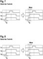
- Fig. 9 The right-hand illustration shows a first embodiment of the proposed method, the left-hand illustration represents the switching signals without modification according to the invention. It can be seen that the duty cycles of the three switching signals are similar, whereby the difference in the duty cycles of the three switching signals is preferably less than approx. 20% to approx. 30%. In this case, when changing sectors, the rising edges of the three Switching signals are fixed so that the minimum measurement time T M is provided for performing the 1-shunt current measurement.
- Fig. 11 and Fig. 12 shows a further embodiment of the proposed method, in which case there is a large difference between the duty cycles of at least two PWM switching signals, so that the method of Fig. 9 and Fig. 10 would not be applicable.
- the PWM switching signals are designed or arranged in such a way that the measurement is carried out alternately on the rising edges (right illustration of Fig. 11 ) or after the sector change at the falling edges (right representation of Fig. 12 ). In this case too, it can be seen that the switching signals do not exhibit any significant jumps as shown in the right-hand illustrations, thus generating a smooth phase current curve.
- this corresponds to a design that is used in particular for medium and high electrical motor voltage amplitudes, whereby the position of the switching edges corresponds to the size ratio of the Duty cycles on the three half-bridges are shifted if a 1-shunt current measurement would not be possible with the original (unchanged) switching patterns.
- a measurement of the shunt current I R is carried out on the positive switching edges or on the negative switching edges. This procedure ensures that the position of the switching edges remains unchanged during the sector change, which advantageously avoids jumps in the switching edges and thus in the phase current curves.
- the switching signals are shifted to the left on the phase with the larger duty cycle and to the right on the phase with the smaller duty cycle. If, when measuring the electrical shunt current I R on the negative switching edges, two phases have a similar duty cycle, the switching signals are shifted to the right on the phase with the larger duty cycle and to the left on the phase with the smaller duty cycle.
- the proposed method advantageously does not require any additional hardware, but can be implemented exclusively using software, with suitable algorithms being programmed into a microcontroller. This supports the easy adaptability and modifiability of the method.
- the proposed method can be advantageously implemented for both permanent- and separately excited synchronous machines.
- the proposed method was described using a three-phase synchronous machine as an example, but it should be noted that the proposed method can also be used for single-, two-, four-, five- and multi-phase synchronous machines.
- the proposed method was described using the high-side switches T1, T3, T5 as an example. However, it goes without saying that the method can also be implemented using the low-side switches T2, T4, T6.
- Fig. 13 shows a basic sequence of a proposed method for operating an electrical synchronous machine.
- center-centered pulse-width modulated switching signals are generated for switching elements T1...T6 of half-bridges, wherein two of the switching elements T1...T6 are each connected to form a half-bridge, wherein second switching elements T4...T6 of each half-bridge are controlled complementarily to first switching elements T1...T3 of each half-bridge, provided that this provides a sufficient minimum measurement duration T M during which the switching signals of switching elements T1...T6 of two half-bridges are at different potentials.
- pulse width modulated switching signals are generated for the switching elements T1...T6 of the half-bridges, which deviate from the centering at least so far that a sufficient minimum measurement duration T M is provided, wherein the switching signals of the switching elements T1...T6 are designed such that temporal jumps corresponding to the minimum measurement duration T M in the switching signals of the switching elements T1...T6 are avoided, and wherein a 1-shunt current measurement is carried out within the provided minimum measurement duration T M.
- Fig. 14 shows a basic block diagram of a device 200 for operating an electrical synchronous machine.
- a generating device 210 for generating center-centered pulse width modulated switching signals for the switching elements T1 ... T6 (not shown) of half bridges (not shown) can be seen, whereby two of the switching elements T1...T6 are connected to are each connected to a half-bridge, with second switching elements T4...T6 of each half-bridge being controlled complementarily to first switching elements T1...T3 of each half-bridge.
- the generation device is functionally connected to a measuring device 220 for carrying out a 1-shunt current measurement, with a defined minimum measurement duration T M being provided by means of the switching signals of the switching elements T1...T6, during which two switching signals of a half-bridge are at different potentials, with the switching signals of the switching elements T1...T6 being able to be formed by means of the generation device 210 in such a way that temporal jumps in the switching signals of the switching elements T1...T6 corresponding to the minimum measurement duration T M are avoided.
- a temporal jump occurs when there is a change from one PWM cycle to the next from a left shift to a right shift or vice versa.
- the switching signals should preferably only change slightly from one PWM cycle to the next and should not have any large jumps in time.
- the switching signals should preferably be shifted to the right or left, deviating from the center position, in order to obtain sufficient measurement time. In particular, a change from one PWM cycle to the next from a left shift to a right shift or vice versa should be avoided.
- the voltage vector generated by the three half bridges lies within a hexagon according to Figure 6 .
- the voltage vector When the synchronous electric machine is operating, the voltage vector usually rotates.
- a sector change means that the voltage vector changes from one of the sectors of the hexagon to another.
- the PWM shift in two half-bridges is changed at each sector change, one half-bridge from left shift to right shift, the other half-bridge in the opposite direction. This causes noise, particularly due to time jumps, and is remedied by the invention.
Landscapes
- Engineering & Computer Science (AREA)
- Power Engineering (AREA)
- Control Of Ac Motors In General (AREA)
- Inverter Devices (AREA)
Claims (11)
- Procédé pour faire fonctionner une machine synchrone électrique, comprenant les étapes :- génération de signaux de commutation modulés en largeur d'impulsion à centrage central pour des éléments de commutation (T1...T6) de demi-ponts, à chaque fois deux des éléments de commutation (T1... T6) étant respectivement connectés en un demi-pont, des deuxièmes éléments de commutation (T4...T6) de chaque demi-pont étant commandés de manière complémentaire aux premiers éléments de commutation (T1...T3) de chaque demi-pont, pour autant qu'une durée de mesure minimale (TM) suffisante soit ainsi mise à disposition, pendant laquelle les signaux de commutation des éléments de commutation (T1...T6) de deux demi-ponts se trouvent à des potentiels différents ;- sans quoi :- génération de signaux de commutation modulés en largeur d'impulsion pour les éléments de commutation (T1...T6) des demi-ponts, qui s'écartent du centrage central au moins suffisamment pour qu'une durée de mesure minimale (TM) suffisante soit mise à disposition,
les signaux de commutation des éléments de commutation (T1...T6) étant configurés de telle sorte que des sauts temporels correspondant à la durée de mesure minimale (TM) dans les signaux de commutation des éléments de commutation (T1...T6) sont évités,- réalisation d'une mesure de courant à 1 shunt à l'intérieur de la durée de mesure minimale (TM) mise à disposition,caractérisé en ce que, dans le cas où au moins deux signaux de commutation des premiers éléments de commutation (T1, T3, T5) présentent un rapport cyclique différent d'une grandeur définie, dans le cas d'une modification des rapports de grandeur des signaux de commutation lors d'une transition d'un cycle de commutation au suivant, les signaux de commutation sont configurés de telle sorte que les mesures de courant à 1 shunt sont effectuées respectivement lors des fronts changeants des signaux de commutation. - Procédé selon la revendication 1, dans lequel, dans le cas où, lors de la mesure de courant à 1 shunt sur les fronts de commutation positifs, deux signaux de commutation d'éléments de commutation (T1, T2, T3) différents présentent un rapport cyclique similaire, les signaux de commutation des éléments de commutation (T1, T2, T3) ayant le rapport cyclique le plus grand sont décalés vers la gauche, et le signal de commutation de l'élément de commutation (T1, T2, T3) ayant le rapport cyclique le plus petit vers la droite.
- Procédé selon l'une des revendications précédentes, dans lequel, dans le cas où, lors de la mesure de courant à 1 shunt sur les fronts de commutation négatifs, deux signaux de commutation d'éléments de commutation (T1, T2, T3) différents présentent un rapport cyclique similaire, les signaux de commutation des éléments de commutation (T1, T2, T3) ayant le rapport cyclique le plus grand sont décalés vers la droite, et le signal de commutation de l'élément de commutation (T1, T2, T3) ayant le rapport cyclique le plus petit vers la gauche.
- Procédé selon l'une des revendications précédentes, dans lequel, dans le cas où les signaux de commutation des premiers éléments de commutation (T1, T3, T5) présentent un rapport cyclique similaire défini, les fronts montants des trois signaux de commutation des premiers éléments de commutation (T1, T3, T5), lors desquels est effectuée la mesure de courant à 1 shunt, sont fixes les uns par rapport aux autres dans leur séquence chronologique et sont configurés de telle sorte que la durée de mesure minimale (TM) est mise à disposition entre les signaux de commutation des premiers éléments de commutation (T1, T3, T5), la mesure de courant à 1 shunt étant effectuée lors des fronts montants des signaux de commutation des premiers éléments de commutation (T1, T3, T5) dans la première moitié de la période PWM.
- Procédé selon l'une des revendications 1 à 3, dans lequel, dans le cas où les signaux de commutation des premiers éléments de commutation (T1, T3, T5) présentent un rapport cyclique similaire défini, les fronts descendants des trois signaux de commutation des premiers éléments de commutation (T1, T3, T5), lors desquels est effectuée la mesure de courant à 1 shunt, sont fixes les uns par rapport aux autres dans leur séquence chronologique et sont configurés de telle sorte que la durée de mesure minimale (TM) est mise à disposition entre les signaux de commutation des premiers éléments de commutation (T1, T3, T5), la mesure de courant à 1 shunt étant effectuée lors des fronts descendants des signaux de commutation des premiers éléments de commutation (T1, T3, T5) dans la deuxième moitié de la période PWM.
- Procédé selon la revendication 4 ou 5, les rapports cycliques des trois signaux de commutation des éléments de commutation (T1, T3, T5) étant similaires et la différence dans les rapports cycliques des trois signaux de commutation étant de préférence inférieure à environ 20 % jusqu'à environ 30 %.
- Procédé selon l'une des revendications précédentes, dans lequel, dans le cas où au moins deux signaux de commutation des premiers éléments de commutation (T1, T3, T5) présentent un rapport cyclique différent d'une valeur définie, la différence de rapport cyclique est supérieure d'environ 25 % jusqu'à environ 100 %.
- Procédé selon l'une des revendications précédentes, le procédé étant mis en oeuvre pour une machine synchrone à excitation permanente ou à excitation séparée.
- Agencement (200) pour faire fonctionner une machine synchrone, comprenant :- un dispositif de génération (210) destiné à générer des signaux de commutation modulés en largeur d'impulsion à centrage central pour des éléments de commutation (T1...T6) de demi-ponts, à chaque fois deux des éléments de commutation (T1...T6) étant respectivement connectés en un demi-pont, des deuxièmes éléments de commutation (T4...T6) de chaque demi-pont étant commandés de manière complémentaire aux premiers éléments de commutation (T1...T3) de chaque demi-pont, pour autant qu'une durée de mesure minimale (TM) suffisante soit ainsi mise à disposition, pendant laquelle les signaux de commutation des éléments de commutation (T1...T6) de deux demi-ponts se trouvent à des potentiels différents,- dans le cas contraire : destiné à générer de signaux de commutation modulés en largeur d'impulsion pour les éléments de commutation (T6) des demi-ponts, qui s'écartent du centrage central au moins suffisamment pour qu'une durée de mesure minimale (TM) suffisante soit mise à disposition ;
les signaux de commutation des éléments de commutation (T1 ... T6) pouvant être configuré au moyen du dispositif de génération (210) de telle sorte que des sauts temporels dans les signaux de commutation des éléments de commutation (T1 ... T6) correspondant à la durée de mesure minimale soient évités,- un dispositif de mesure (220) destiné à effectuer une mesure de courant à 1 shunt, une durée de mesure minimale définie (TM) étant mise à disposition au moyen des signaux de commutation des éléments de commutation (T1...T6), pendant laquelle deux signaux de commutation d'un demi-pont se trouvent à des potentiels différents,caractérisé en ce que, dans le cas où au moins deux signaux de commutation des premiers éléments de commutation (T1, T3, T5) présentent un rapport cyclique différent d'une grandeur définie, dans le cas d'une modification des rapports de grandeur des signaux de commutation lors d'une transition d'un cycle de commutation au suivant, les signaux de commutation sont configurés de telle sorte que les mesures de courant à 1 shunt sont effectuées respectivement lors des fronts changeants des signaux de commutation. - Produit de programme informatique comprenant des instructions qui amènent l'agencement (100) destiné à faire fonctionner une machine électrique synchrone (200) selon la revendication 9 à mettre en oeuvre le procédé selon l'une des revendications 1 à 8.
- Support de stockage lisible par ordinateur, sur lequel est enregistré le produit de programme informatique selon la revendication 10.
Applications Claiming Priority (2)
| Application Number | Priority Date | Filing Date | Title |
|---|---|---|---|
| DE102018200085.9A DE102018200085A1 (de) | 2018-01-04 | 2018-01-04 | Verfahren zum Betreiben einer elektrischen Synchronmaschine |
| PCT/EP2018/085261 WO2019134816A1 (fr) | 2018-01-04 | 2018-12-17 | Procédé de fonctionnement d'une machine synchrone électrique |
Publications (2)
| Publication Number | Publication Date |
|---|---|
| EP3735741A1 EP3735741A1 (fr) | 2020-11-11 |
| EP3735741B1 true EP3735741B1 (fr) | 2024-11-13 |
Family
ID=64755553
Family Applications (1)
| Application Number | Title | Priority Date | Filing Date |
|---|---|---|---|
| EP18825652.3A Active EP3735741B1 (fr) | 2018-01-04 | 2018-12-17 | Procédé et dispositif pour faire fonctionner une machine électrique synchrone avec mesure de courant à 1 shunt |
Country Status (7)
| Country | Link |
|---|---|
| US (1) | US11404990B2 (fr) |
| EP (1) | EP3735741B1 (fr) |
| CN (1) | CN111527691B (fr) |
| DE (1) | DE102018200085A1 (fr) |
| HU (1) | HUE070048T2 (fr) |
| PL (1) | PL3735741T3 (fr) |
| WO (1) | WO2019134816A1 (fr) |
Families Citing this family (1)
| Publication number | Priority date | Publication date | Assignee | Title |
|---|---|---|---|---|
| DE102022208793A1 (de) | 2022-08-25 | 2024-03-07 | Robert Bosch Gesellschaft mit beschränkter Haftung | Verfahren zum Ansteuern einer Anordnung mit mindestens einem Leistungsschalter |
Family Cites Families (14)
| Publication number | Priority date | Publication date | Assignee | Title |
|---|---|---|---|---|
| DE102004049251A1 (de) * | 2004-09-30 | 2006-04-06 | Robert Bosch Gmbh | Gerät zum Ermitteln von elektrischen Größen |
| DE102005062759A1 (de) * | 2005-12-28 | 2007-07-05 | Robert Bosch Gmbh | Verfahren und Vorrichtung zur Strommessung |
| WO2011099122A1 (fr) * | 2010-02-10 | 2011-08-18 | 株式会社 日立製作所 | Dispositif de conversion de puissance |
| DE102010041275B4 (de) * | 2010-09-23 | 2019-11-28 | Robert Bosch Gmbh | Verfahren zur Überprüfung der ordnungsgemäßen Funktionsweise eines Stromsensors |
| DE102011003897A1 (de) * | 2011-02-10 | 2012-08-16 | Robert Bosch Gmbh | Verfahren und Vorrichtung zur Strommessung |
| CN102832880B (zh) * | 2011-06-17 | 2017-03-01 | 迪尔阿扣基金两合公司 | 控制转换器的方法 |
| JP2015050909A (ja) * | 2013-09-04 | 2015-03-16 | オムロンオートモーティブエレクトロニクス株式会社 | モータ制御装置 |
| JP6099148B2 (ja) * | 2013-09-04 | 2017-03-22 | オムロンオートモーティブエレクトロニクス株式会社 | モータ制御装置 |
| DE102014202634A1 (de) * | 2014-02-13 | 2015-08-13 | Robert Bosch Gmbh | Stromdetektionseinrichtung und Verfahren zum Erfassen eines elektrischen Stroms |
| DE102015202693A1 (de) | 2014-03-07 | 2015-09-10 | Robert Bosch Gmbh | Verfahren zur Strangstrombestimmung in einem elektrischen Mehrphasensystem |
| DE102014210325A1 (de) * | 2014-06-02 | 2015-12-03 | Robert Bosch Gmbh | Spannungswandler und Verfahren |
| US9401674B2 (en) * | 2014-06-11 | 2016-07-26 | Nidec Motor Corporation | Single-shunt current sensing for multi-phase motor |
| DE102014018431A1 (de) * | 2014-12-12 | 2016-06-16 | Audi Ag | Verfahren zum Betreiben einer elektrischen Maschine |
| CN106411221B (zh) * | 2016-10-14 | 2020-11-24 | 江先武 | 一种用于电机宽速的电流检控装置 |
-
2018
- 2018-01-04 DE DE102018200085.9A patent/DE102018200085A1/de not_active Withdrawn
- 2018-12-17 EP EP18825652.3A patent/EP3735741B1/fr active Active
- 2018-12-17 WO PCT/EP2018/085261 patent/WO2019134816A1/fr not_active Ceased
- 2018-12-17 HU HUE18825652A patent/HUE070048T2/hu unknown
- 2018-12-17 US US16/960,123 patent/US11404990B2/en active Active
- 2018-12-17 PL PL18825652.3T patent/PL3735741T3/pl unknown
- 2018-12-17 CN CN201880085231.3A patent/CN111527691B/zh active Active
Also Published As
| Publication number | Publication date |
|---|---|
| CN111527691B (zh) | 2024-05-14 |
| DE102018200085A1 (de) | 2019-07-04 |
| HUE070048T2 (hu) | 2025-05-28 |
| US11404990B2 (en) | 2022-08-02 |
| PL3735741T3 (pl) | 2025-03-03 |
| EP3735741A1 (fr) | 2020-11-11 |
| WO2019134816A1 (fr) | 2019-07-11 |
| CN111527691A (zh) | 2020-08-11 |
| US20210075358A1 (en) | 2021-03-11 |
Similar Documents
| Publication | Publication Date | Title |
|---|---|---|
| EP2596577B1 (fr) | Procédé et dispositif de commande d'une machine électrique polyphasée, et système moteur | |
| DE102007040560A1 (de) | Verfahren zur Ansteuerung eines Umrichters sowie zugehörige Vorrichtung | |
| DE112008001649T5 (de) | Pseudowechselrichter mit Stromzwischenkreis mit Leitung für 120 Grad | |
| WO2015165848A1 (fr) | Procédé de reproduction d'un moteur triphasé à courant continu sans balai au moyen d'un émulateur de charge | |
| EP2067249B1 (fr) | Procede de fonctionnement d'un moteur electrique a commutation electronique | |
| WO2012107325A1 (fr) | Procédé et dispositif de mesure de courant | |
| WO2019015894A1 (fr) | Machine électrique | |
| DE102014107949A1 (de) | Verfahren und Vorrichtung zur Erkennung eines Nulldurchgangs eines Stroms durch einen Strang eines bürstenlosen Gleichstrom- motors | |
| DE102016215175B4 (de) | Verfahren zum Betreiben einer elektrischen Maschine und elektrische Maschine | |
| EP3735741B1 (fr) | Procédé et dispositif pour faire fonctionner une machine électrique synchrone avec mesure de courant à 1 shunt | |
| EP2899879A2 (fr) | Procédé de fonctionnement et dispositif de commande d'une machine à rotation électrique sans brosse | |
| DE102017211196A1 (de) | Verfahren zum Betreiben einer elektronisch kommutierten Synchronmaschine und Ansteuerschaltung | |
| DE102007004094A1 (de) | Verfahren und Vorrichtung zur Steuerung einer mittels Pulsweitenmodulation steuerbaren Drehstrommaschine mit mehreren Phasenwicklungen | |
| DE10207338A1 (de) | Verfahren und Vorrichtung zur Erfassung der Motorposition eines Elektromotors | |
| DE102014115607A1 (de) | Verfahren und Schaltungsanordnung zur Lagestabilisierung eines Rotors gegenüber einem Stator in einem Elektromotor | |
| EP1748543B1 (fr) | Méthode et dispositif de régulation d'une machine électrique | |
| DE10163886A1 (de) | Verfahren zur elektronischen Kommutierung eines bürstenlosen Gleichstrommotors | |
| EP3285394B1 (fr) | Procédé de fonctionnement d'une machine électrique et machine électrique | |
| DE102020100132A1 (de) | Verfahren zur Bestimmung einer Rotorposition eines Elektromotors | |
| DE102023004626B3 (de) | Betreiben von Schaltelementen eines Wechselrichters | |
| DE102014217699A1 (de) | Steuerung einer Drehfeldmaschine | |
| DE19926963A1 (de) | Hysteresesteuerung in Motoren mit geschalteter Reluktanz | |
| DE102019204728A1 (de) | Verbindungseinrichtung für einen elektrischen Permanentmagnet-Synchronmotor | |
| EP2467931B1 (fr) | Procede et dispositif de commande d'un moteur electrique | |
| DE102018213749A1 (de) | Vorrichtung zum Betreiben eines elektrischen Verbrauchers, Verbraucher und Verfahren |
Legal Events
| Date | Code | Title | Description |
|---|---|---|---|
| STAA | Information on the status of an ep patent application or granted ep patent |
Free format text: STATUS: UNKNOWN |
|
| STAA | Information on the status of an ep patent application or granted ep patent |
Free format text: STATUS: THE INTERNATIONAL PUBLICATION HAS BEEN MADE |
|
| PUAI | Public reference made under article 153(3) epc to a published international application that has entered the european phase |
Free format text: ORIGINAL CODE: 0009012 |
|
| STAA | Information on the status of an ep patent application or granted ep patent |
Free format text: STATUS: REQUEST FOR EXAMINATION WAS MADE |
|
| 17P | Request for examination filed |
Effective date: 20200804 |
|
| AK | Designated contracting states |
Kind code of ref document: A1 Designated state(s): AL AT BE BG CH CY CZ DE DK EE ES FI FR GB GR HR HU IE IS IT LI LT LU LV MC MK MT NL NO PL PT RO RS SE SI SK SM TR |
|
| AX | Request for extension of the european patent |
Extension state: BA ME |
|
| DAV | Request for validation of the european patent (deleted) | ||
| DAX | Request for extension of the european patent (deleted) | ||
| STAA | Information on the status of an ep patent application or granted ep patent |
Free format text: STATUS: EXAMINATION IS IN PROGRESS |
|
| 17Q | First examination report despatched |
Effective date: 20220425 |
|
| GRAP | Despatch of communication of intention to grant a patent |
Free format text: ORIGINAL CODE: EPIDOSNIGR1 |
|
| STAA | Information on the status of an ep patent application or granted ep patent |
Free format text: STATUS: GRANT OF PATENT IS INTENDED |
|
| INTG | Intention to grant announced |
Effective date: 20240709 |
|
| GRAS | Grant fee paid |
Free format text: ORIGINAL CODE: EPIDOSNIGR3 |
|
| GRAA | (expected) grant |
Free format text: ORIGINAL CODE: 0009210 |
|
| STAA | Information on the status of an ep patent application or granted ep patent |
Free format text: STATUS: THE PATENT HAS BEEN GRANTED |
|
| AK | Designated contracting states |
Kind code of ref document: B1 Designated state(s): AL AT BE BG CH CY CZ DE DK EE ES FI FR GB GR HR HU IE IS IT LI LT LU LV MC MK MT NL NO PL PT RO RS SE SI SK SM TR |
|
| REG | Reference to a national code |
Ref country code: GB Ref legal event code: FG4D Free format text: NOT ENGLISH |
|
| REG | Reference to a national code |
Ref country code: CH Ref legal event code: EP |
|
| REG | Reference to a national code |
Ref country code: DE Ref legal event code: R096 Ref document number: 502018015329 Country of ref document: DE |
|
| REG | Reference to a national code |
Ref country code: IE Ref legal event code: FG4D Free format text: LANGUAGE OF EP DOCUMENT: GERMAN |
|
| REG | Reference to a national code |
Ref country code: LT Ref legal event code: MG9D |
|
| REG | Reference to a national code |
Ref country code: NL Ref legal event code: MP Effective date: 20241113 |
|
| PG25 | Lapsed in a contracting state [announced via postgrant information from national office to epo] |
Ref country code: IS Free format text: LAPSE BECAUSE OF FAILURE TO SUBMIT A TRANSLATION OF THE DESCRIPTION OR TO PAY THE FEE WITHIN THE PRESCRIBED TIME-LIMIT Effective date: 20250313 Ref country code: PT Free format text: LAPSE BECAUSE OF FAILURE TO SUBMIT A TRANSLATION OF THE DESCRIPTION OR TO PAY THE FEE WITHIN THE PRESCRIBED TIME-LIMIT Effective date: 20250313 Ref country code: HR Free format text: LAPSE BECAUSE OF FAILURE TO SUBMIT A TRANSLATION OF THE DESCRIPTION OR TO PAY THE FEE WITHIN THE PRESCRIBED TIME-LIMIT Effective date: 20241113 |
|
| PG25 | Lapsed in a contracting state [announced via postgrant information from national office to epo] |
Ref country code: FI Free format text: LAPSE BECAUSE OF FAILURE TO SUBMIT A TRANSLATION OF THE DESCRIPTION OR TO PAY THE FEE WITHIN THE PRESCRIBED TIME-LIMIT Effective date: 20241113 Ref country code: NL Free format text: LAPSE BECAUSE OF FAILURE TO SUBMIT A TRANSLATION OF THE DESCRIPTION OR TO PAY THE FEE WITHIN THE PRESCRIBED TIME-LIMIT Effective date: 20241113 |
|
| PG25 | Lapsed in a contracting state [announced via postgrant information from national office to epo] |
Ref country code: BG Free format text: LAPSE BECAUSE OF FAILURE TO SUBMIT A TRANSLATION OF THE DESCRIPTION OR TO PAY THE FEE WITHIN THE PRESCRIBED TIME-LIMIT Effective date: 20241113 |
|
| PG25 | Lapsed in a contracting state [announced via postgrant information from national office to epo] |
Ref country code: ES Free format text: LAPSE BECAUSE OF FAILURE TO SUBMIT A TRANSLATION OF THE DESCRIPTION OR TO PAY THE FEE WITHIN THE PRESCRIBED TIME-LIMIT Effective date: 20241113 |
|
| PG25 | Lapsed in a contracting state [announced via postgrant information from national office to epo] |
Ref country code: NO Free format text: LAPSE BECAUSE OF FAILURE TO SUBMIT A TRANSLATION OF THE DESCRIPTION OR TO PAY THE FEE WITHIN THE PRESCRIBED TIME-LIMIT Effective date: 20250213 |
|
| PG25 | Lapsed in a contracting state [announced via postgrant information from national office to epo] |
Ref country code: LV Free format text: LAPSE BECAUSE OF FAILURE TO SUBMIT A TRANSLATION OF THE DESCRIPTION OR TO PAY THE FEE WITHIN THE PRESCRIBED TIME-LIMIT Effective date: 20241113 Ref country code: GR Free format text: LAPSE BECAUSE OF FAILURE TO SUBMIT A TRANSLATION OF THE DESCRIPTION OR TO PAY THE FEE WITHIN THE PRESCRIBED TIME-LIMIT Effective date: 20250214 |
|
| PG25 | Lapsed in a contracting state [announced via postgrant information from national office to epo] |
Ref country code: RS Free format text: LAPSE BECAUSE OF FAILURE TO SUBMIT A TRANSLATION OF THE DESCRIPTION OR TO PAY THE FEE WITHIN THE PRESCRIBED TIME-LIMIT Effective date: 20250213 |
|
| REG | Reference to a national code |
Ref country code: HU Ref legal event code: AG4A Ref document number: E070048 Country of ref document: HU |
|
| PG25 | Lapsed in a contracting state [announced via postgrant information from national office to epo] |
Ref country code: SM Free format text: LAPSE BECAUSE OF FAILURE TO SUBMIT A TRANSLATION OF THE DESCRIPTION OR TO PAY THE FEE WITHIN THE PRESCRIBED TIME-LIMIT Effective date: 20241113 |
|
| PG25 | Lapsed in a contracting state [announced via postgrant information from national office to epo] |
Ref country code: DK Free format text: LAPSE BECAUSE OF FAILURE TO SUBMIT A TRANSLATION OF THE DESCRIPTION OR TO PAY THE FEE WITHIN THE PRESCRIBED TIME-LIMIT Effective date: 20241113 |
|
| PG25 | Lapsed in a contracting state [announced via postgrant information from national office to epo] |
Ref country code: EE Free format text: LAPSE BECAUSE OF FAILURE TO SUBMIT A TRANSLATION OF THE DESCRIPTION OR TO PAY THE FEE WITHIN THE PRESCRIBED TIME-LIMIT Effective date: 20241113 |
|
| PG25 | Lapsed in a contracting state [announced via postgrant information from national office to epo] |
Ref country code: RO Free format text: LAPSE BECAUSE OF FAILURE TO SUBMIT A TRANSLATION OF THE DESCRIPTION OR TO PAY THE FEE WITHIN THE PRESCRIBED TIME-LIMIT Effective date: 20241113 |
|
| PG25 | Lapsed in a contracting state [announced via postgrant information from national office to epo] |
Ref country code: SK Free format text: LAPSE BECAUSE OF FAILURE TO SUBMIT A TRANSLATION OF THE DESCRIPTION OR TO PAY THE FEE WITHIN THE PRESCRIBED TIME-LIMIT Effective date: 20241113 |
|
| PG25 | Lapsed in a contracting state [announced via postgrant information from national office to epo] |
Ref country code: IT Free format text: LAPSE BECAUSE OF FAILURE TO SUBMIT A TRANSLATION OF THE DESCRIPTION OR TO PAY THE FEE WITHIN THE PRESCRIBED TIME-LIMIT Effective date: 20241113 |
|
| REG | Reference to a national code |
Ref country code: CH Ref legal event code: PL |
|
| REG | Reference to a national code |
Ref country code: DE Ref legal event code: R097 Ref document number: 502018015329 Country of ref document: DE |
|
| PG25 | Lapsed in a contracting state [announced via postgrant information from national office to epo] |
Ref country code: LU Free format text: LAPSE BECAUSE OF NON-PAYMENT OF DUE FEES Effective date: 20241217 |
|
| PG25 | Lapsed in a contracting state [announced via postgrant information from national office to epo] |
Ref country code: SE Free format text: LAPSE BECAUSE OF FAILURE TO SUBMIT A TRANSLATION OF THE DESCRIPTION OR TO PAY THE FEE WITHIN THE PRESCRIBED TIME-LIMIT Effective date: 20241113 |
|
| PG25 | Lapsed in a contracting state [announced via postgrant information from national office to epo] |
Ref country code: MC Free format text: LAPSE BECAUSE OF FAILURE TO SUBMIT A TRANSLATION OF THE DESCRIPTION OR TO PAY THE FEE WITHIN THE PRESCRIBED TIME-LIMIT Effective date: 20241113 |
|
| PLBE | No opposition filed within time limit |
Free format text: ORIGINAL CODE: 0009261 |
|
| STAA | Information on the status of an ep patent application or granted ep patent |
Free format text: STATUS: NO OPPOSITION FILED WITHIN TIME LIMIT |
|
| REG | Reference to a national code |
Ref country code: BE Ref legal event code: MM Effective date: 20241231 |
|
| PG25 | Lapsed in a contracting state [announced via postgrant information from national office to epo] |
Ref country code: BE Free format text: LAPSE BECAUSE OF NON-PAYMENT OF DUE FEES Effective date: 20241231 |
|
| PG25 | Lapsed in a contracting state [announced via postgrant information from national office to epo] |
Ref country code: CH Free format text: LAPSE BECAUSE OF NON-PAYMENT OF DUE FEES Effective date: 20241231 |
|
| 26N | No opposition filed |
Effective date: 20250814 |
|
| PG25 | Lapsed in a contracting state [announced via postgrant information from national office to epo] |
Ref country code: IE Free format text: LAPSE BECAUSE OF NON-PAYMENT OF DUE FEES Effective date: 20241217 |
|
| GBPC | Gb: european patent ceased through non-payment of renewal fee |
Effective date: 20250213 |
|
| PG25 | Lapsed in a contracting state [announced via postgrant information from national office to epo] |
Ref country code: GB Free format text: LAPSE BECAUSE OF NON-PAYMENT OF DUE FEES Effective date: 20250213 |
|
| PGFP | Annual fee paid to national office [announced via postgrant information from national office to epo] |
Ref country code: HU Payment date: 20251212 Year of fee payment: 8 Ref country code: FR Payment date: 20251218 Year of fee payment: 8 |
|
| PGFP | Annual fee paid to national office [announced via postgrant information from national office to epo] |
Ref country code: CZ Payment date: 20251204 Year of fee payment: 8 |
|
| PGFP | Annual fee paid to national office [announced via postgrant information from national office to epo] |
Ref country code: PL Payment date: 20251205 Year of fee payment: 8 |
|
| REG | Reference to a national code |
Ref country code: AT Ref legal event code: MM01 Ref document number: 1742435 Country of ref document: AT Kind code of ref document: T Effective date: 20241217 |
|
| PGFP | Annual fee paid to national office [announced via postgrant information from national office to epo] |
Ref country code: DE Payment date: 20260223 Year of fee payment: 8 |
|
| PG25 | Lapsed in a contracting state [announced via postgrant information from national office to epo] |
Ref country code: AT Free format text: LAPSE BECAUSE OF NON-PAYMENT OF DUE FEES Effective date: 20241217 |