EP3735885A1 - Appareil d'aspiration - Google Patents
Appareil d'aspiration Download PDFInfo
- Publication number
- EP3735885A1 EP3735885A1 EP20170552.2A EP20170552A EP3735885A1 EP 3735885 A1 EP3735885 A1 EP 3735885A1 EP 20170552 A EP20170552 A EP 20170552A EP 3735885 A1 EP3735885 A1 EP 3735885A1
- Authority
- EP
- European Patent Office
- Prior art keywords
- positioning
- suction device
- positioning device
- housing
- collecting container
- Prior art date
- Legal status (The legal status is an assumption and is not a legal conclusion. Google has not performed a legal analysis and makes no representation as to the accuracy of the status listed.)
- Granted
Links
Images

Classifications
-
- A—HUMAN NECESSITIES
- A47—FURNITURE; DOMESTIC ARTICLES OR APPLIANCES; COFFEE MILLS; SPICE MILLS; SUCTION CLEANERS IN GENERAL
- A47L—DOMESTIC WASHING OR CLEANING; SUCTION CLEANERS IN GENERAL
- A47L9/00—Details or accessories of suction cleaners, e.g. mechanical means for controlling the suction or for effecting pulsating action; Storing devices specially adapted to suction cleaners or parts thereof; Carrying-vehicles specially adapted for suction cleaners
- A47L9/10—Filters; Dust separators; Dust removal; Automatic exchange of filters
- A47L9/14—Bags or the like; Rigid filtering receptacles; Attachment of, or closures for, bags or receptacles
- A47L9/1427—Means for mounting or attaching bags or filtering receptacles in suction cleaners; Adapters
-
- A—HUMAN NECESSITIES
- A47—FURNITURE; DOMESTIC ARTICLES OR APPLIANCES; COFFEE MILLS; SPICE MILLS; SUCTION CLEANERS IN GENERAL
- A47L—DOMESTIC WASHING OR CLEANING; SUCTION CLEANERS IN GENERAL
- A47L9/00—Details or accessories of suction cleaners, e.g. mechanical means for controlling the suction or for effecting pulsating action; Storing devices specially adapted to suction cleaners or parts thereof; Carrying-vehicles specially adapted for suction cleaners
- A47L9/10—Filters; Dust separators; Dust removal; Automatic exchange of filters
- A47L9/16—Arrangement or disposition of cyclones or other devices with centrifugal action
- A47L9/1683—Dust collecting chambers; Dust collecting receptacles
-
- A—HUMAN NECESSITIES
- A47—FURNITURE; DOMESTIC ARTICLES OR APPLIANCES; COFFEE MILLS; SPICE MILLS; SUCTION CLEANERS IN GENERAL
- A47L—DOMESTIC WASHING OR CLEANING; SUCTION CLEANERS IN GENERAL
- A47L9/00—Details or accessories of suction cleaners, e.g. mechanical means for controlling the suction or for effecting pulsating action; Storing devices specially adapted to suction cleaners or parts thereof; Carrying-vehicles specially adapted for suction cleaners
- A47L9/10—Filters; Dust separators; Dust removal; Automatic exchange of filters
- A47L9/16—Arrangement or disposition of cyclones or other devices with centrifugal action
- A47L9/1691—Mounting or coupling means for cyclonic chamber or dust receptacles
-
- B—PERFORMING OPERATIONS; TRANSPORTING
- B04—CENTRIFUGAL APPARATUS OR MACHINES FOR CARRYING-OUT PHYSICAL OR CHEMICAL PROCESSES
- B04C—APPARATUS USING FREE VORTEX FLOW, e.g. CYCLONES
- B04C5/00—Apparatus in which the axial direction of the vortex is reversed
- B04C5/02—Construction of inlets by which the vortex flow is generated, e.g. tangential admission, the fluid flow being forced to follow a downward path by spirally wound bulkheads, or with slightly downwardly-directed tangential admission
- B04C5/04—Tangential inlets
-
- B—PERFORMING OPERATIONS; TRANSPORTING
- B04—CENTRIFUGAL APPARATUS OR MACHINES FOR CARRYING-OUT PHYSICAL OR CHEMICAL PROCESSES
- B04C—APPARATUS USING FREE VORTEX FLOW, e.g. CYCLONES
- B04C5/00—Apparatus in which the axial direction of the vortex is reversed
- B04C5/14—Construction of the underflow ducting; Apex constructions; Discharge arrangements ; discharge through sidewall provided with a few slits or perforations
- B04C5/185—Dust collectors
- B04C5/187—Dust collectors forming an integral part of the vortex chamber
-
- B—PERFORMING OPERATIONS; TRANSPORTING
- B04—CENTRIFUGAL APPARATUS OR MACHINES FOR CARRYING-OUT PHYSICAL OR CHEMICAL PROCESSES
- B04C—APPARATUS USING FREE VORTEX FLOW, e.g. CYCLONES
- B04C9/00—Combinations with other devices, e.g. fans, expansion chambers, diffusors, water locks
-
- B—PERFORMING OPERATIONS; TRANSPORTING
- B04—CENTRIFUGAL APPARATUS OR MACHINES FOR CARRYING-OUT PHYSICAL OR CHEMICAL PROCESSES
- B04C—APPARATUS USING FREE VORTEX FLOW, e.g. CYCLONES
- B04C9/00—Combinations with other devices, e.g. fans, expansion chambers, diffusors, water locks
- B04C2009/004—Combinations with other devices, e.g. fans, expansion chambers, diffusors, water locks with internal filters, in the cyclone chamber or in the vortex finder
-
- B—PERFORMING OPERATIONS; TRANSPORTING
- B04—CENTRIFUGAL APPARATUS OR MACHINES FOR CARRYING-OUT PHYSICAL OR CHEMICAL PROCESSES
- B04C—APPARATUS USING FREE VORTEX FLOW, e.g. CYCLONES
- B04C9/00—Combinations with other devices, e.g. fans, expansion chambers, diffusors, water locks
- B04C2009/008—Combinations with other devices, e.g. fans, expansion chambers, diffusors, water locks with injection or suction of gas or liquid into the cyclone
Definitions
- the present invention relates to a suction device with the features of the preamble.
- a suction device with a housing, with at least one cyclone chamber, with a collecting container, the collecting container being designed to be detachably connectable to the housing, and with a filter element is already known.
- the present invention is based on a suction device with a housing, with at least one cyclone chamber, with a collecting container, the collecting container being designed to be detachably connectable to the housing, and with a filter element. It is proposed that the suction device has at least one positioning device within the cyclone chamber for positioning at least one collecting element within the cyclone chamber.
- the invention provides a suction device with at least one positioning device, the positioning device making it possible to improve the removal of substance and / or liquid from the collecting container in that the positioning device positions the collecting element within the cyclone chamber.
- the suction device is designed to collect and separate material particles and / or liquids from the air flow.
- the air flow is generated by means of the electric motor.
- the air flow can enter the housing via an air inlet, the air flow being guided into the collecting container by means of a first air channel.
- the collecting container is designed to collect the substance particles and / or the liquids, the collecting container being detachably connected to the housing of the suction device.
- the air flow exits the housing via the filter element from an air outlet.
- the filter element is arranged in the cyclone chamber and, in particular releasably, connected to the housing. This allows the suction device to be adapted to different areas of application.
- adapted filter elements with specific pore sizes can be used, which both effectively separate the particles from the air flow and allow a maximum air flow to pass.
- the filter element can also advantageously be changed in the event of damage, which ensures a high filter performance of the suction device over its service life.
- the air inlet and the air outlet of the suction device can be arranged on opposite sides.
- “Avoided sides” should also be understood to mean, in particular, sides of the suction device which are oriented essentially perpendicular to one another or essentially opposite sides.
- air flow is to be understood in particular as a particle, fluid and / or gas flow which moves along a direction of movement through the suction device.
- a "direction of movement" of the air flow is to be understood in particular as the flow direction of the air flow when the suction device is switched on.
- the direction of movement is directed essentially starting from the air inlet of the suction device in the direction of the air outlet of the suction device.
- the electric motor which is designed to drive at least one fan unit, is advantageously used to generate the air flow.
- the fan unit can be designed, for example, as a radial or axial fan.
- a “cyclone chamber” is to be understood in particular as an area of the suction device in which material and / or fluid particles are separated from an air stream by means of a centrifugal separation mechanism.
- the air flow is advantageously guided tangentially into the cyclone chamber, at least in some areas.
- the air flow inside the cyclone chamber is preferably at least partially circular Railway guided.
- the air flow within the cyclone chamber is at least partially guided on a circular path around the filter element.
- the filter element is advantageously designed to filter substance and / or fluid particles as they exit the cyclone chamber.
- the cyclone chamber is at least partially delimited by the filter element.
- the cyclone chamber is preferably designed at least in sections as a hollow cylinder, in particular the outer diameter of the hollow cylinder being formed by the collecting container and the inner diameter of the hollow cylinder being formed by the filter element.
- the filter element can, for example, be designed as a folded filter.
- the outer surface of the pleated filter corresponds to at least twice the surface area of the pleated filter.
- the filter element is connected to the housing, in particular releasably.
- connection of the filter element to the housing can be a screw connection, a clamp connection, a snap connection, a hook connection or a bayonet connection.
- the bayonet connection enables an easy-to-use and secure connection of the filter element to the housing of the suction device.
- the positioning device is designed for positioning the collecting element within the cyclone chamber, in particular on the collecting container.
- positioning is to be understood as being in a position, in particular a predetermined position. It is also possible for the positioning device to center the collecting element within the cyclone chamber, in particular the collecting container.
- the collecting element can, for example, be made of a flexible material such as a plastic film or a paper bag.
- the collecting element can be designed, for example, as a collecting bag, in particular a dust collecting bag, or as a disposal bag. It is also conceivable that the collecting element is designed as a collecting bucket.
- the collecting container is shaped in such a way that it can accommodate the collecting element. It is conceivable that the collecting container can fix the collecting element.
- the collecting container can position and / or center the collecting element.
- the collecting container can have receiving elements for receiving the collecting element.
- the collecting container can, for example, have clamping, clamping, snap or hook elements as receiving elements, or an at least partially circumferential groove for receiving the Collecting element.
- the collecting element can have connecting elements for connection to the collecting container.
- the connecting elements can be in the form of connecting openings or a rubber-like, circumferential connecting band.
- the positioning device is arranged in a radial direction to a housing axis between the filter element and the collecting container.
- the housing of the suction device is essentially cylindrical, so that at least one longitudinal axis of the housing represents the housing axis.
- the positioning device is arranged between the filter element and the collecting container, leading away from the housing axis in the radial direction.
- the positioning device is arranged coaxially between the filter element and the collecting container relative to the housing axis.
- the filter element is arranged on the housing axis.
- the collecting container is essentially cylindrical and is arranged coaxially to the housing axis.
- the positioning device is arranged coaxially to the housing axis.
- the collecting container at least partially accommodates the positioning device.
- the collecting container can hold the positioning device in a non-positive and / or positive manner.
- the collecting container can enclose the positioning device at least partially in the circumferential direction, wherein the circumferential direction can be relative to the housing axis.
- the collecting container covers or encloses the positioning device at least partially in the radial and / or axial direction to the housing axis.
- the positioning device is arranged on the housing.
- the positioning device can be connected to the housing in a detachable or essentially fixed manner.
- “essentially fixed” is to be understood as essentially not easily removable from the housing by a user.
- the positioning device and / or the housing can have at least one connection mechanism for the detachable connection.
- the user can use the positioning device connect to and remove from the housing by means of a connecting mechanism.
- the positioning device can be designed in the manner of a basket. The collecting container can then receive the basket and, in the connected state, arrange it on the housing, so that the basket arranges the collecting element on the collecting container.
- the positioning device can be connected to the housing by means of fastening elements.
- the fastening elements can be screws or nuts, for example.
- the housing can form the positioning device, so that the housing and the positioning device are in one piece.
- the positioning device is designed such that the positioning device arranges the collecting element, in particular during operation of the suction device, on the collecting container.
- the collecting container can receive the positioning device at least partially, in particular in a non-positive and / or positive manner.
- the positioning device preferably releasably arranges the collecting element on an inner surface of the collecting container.
- the positioning device is designed such that it arranges the collecting element on the inner surface of the collecting container by means of at least one radial and / or axial force relative to the housing axis.
- the positioning device can press, press or clamp the collecting element, for example, against the inner surface of the collecting container.
- the radial and / or axial force is preferably directed radially outward, pointing away from the housing axis.
- the positioning device arranges the collecting element on the inner surface of the collecting container in such a way as to prevent the circular path of the air flow within the cyclone chamber around the filter element from being disturbed.
- the positioning device has the effect that the collecting element remains arranged on the inner surface of the collecting container during the operation of the suction device. In this case, the collecting element is pressed, pressed or the like against the inner surface of the collecting container by means of the positioning device.
- the positioning device is additionally designed to hold the collecting element, in particular on the positioning device.
- the positioning device can hold the collecting element in such a way that it can be removed of the collecting element from the collecting container is facilitated. It is also conceivable that the positioning device fixes the collecting element.
- the positioning device is designed to exert at least one further radial and / or axial force relative to the housing axis on the collecting element in order to hold the collecting element.
- the positioning device can, for example, tension, press or clamp the collecting element in the radial and / or axial direction relative to the housing axis.
- the further radial and / or axial force is preferably directed radially outward, pointing away from the housing axis.
- the positioning device has an essentially circular cross section.
- “as essentially circular” should also be understood to mean elliptical, ring-shaped or disk-shaped.
- the positioning device has a pitch circle diameter in the range from 200 mm to 340 mm, in particular 220 mm to 320 mm, very particularly 240 mm to 300 mm.
- the positioning device has a cooling circle diameter in the range from 210 mm to 350 mm, in particular 220 mm to 340 mm, very particularly 220 mm to 330 mm.
- the essentially circular cross section can correlate with the collecting container in such a way that the collecting container can receive the positioning device in a non-positive and / or form-fitting manner and can arrange the collecting element on the collecting container.
- the positioning device has at least one positioning element for positioning the collecting element on the collecting container.
- the positioning element is designed such that it can position the collecting element on the inner surface of the collecting container by means of the radial and / or axial force. It is also possible for the positioning element to arrange the collecting element on the inner surface of the collecting container by means of the radial and / or axial force, in particular to press it.
- the positioning element can center the collecting element, in particular in the collecting container and / or the cyclone chamber.
- the positioning element can, for example, be rod-shaped, rod-shaped with an essentially spherical free end, rod-shaped with essentially a free, curled and rounded end or strip-shaped. The free end of the positioning element is designed in such a way that it has a contact surface with the collecting element increased and at the same time prevents damage to the collecting element, especially when operating the suction device.
- the positioning element has an axial length, relative to the housing axis, in the range from 100 mm to 210 mm, in particular 120 mm to 190 mm, very particularly 140 mm to 170 mm.
- the positioning device has at least one connecting element, the connecting element being designed to connect the positioning device to the housing and / or the collecting container.
- the connecting element can releasably or essentially firmly connect the positioning device to the housing and / or the collecting container.
- the connecting element can connect the positioning device to the housing and / or collecting container in a non-positive, positive and / or cohesive manner.
- the connecting element can have a receiving element for receiving at least the fastening element.
- the positioning device can be connected to the housing and / or the collecting container by means of the fastening element and the receiving element.
- the receiving element can be designed as a receiving opening and the fastening element can be designed as a screw.
- the screw can then connect the connecting element to the housing and / or the collecting container by means of the receiving opening.
- the connecting element has at least one holding element in order to connect the positioning device to the housing and / or the collecting container.
- the holding element can be designed as a snap hook.
- the connection element is shaped as a clamping ring in order to connect the positioning device to the housing and / or the collecting container by means of a clamping connection.
- the connecting element can connect the positioning device to the filter element.
- the positioning device has one or more frame elements for stabilizing the positioning device.
- the frame element is designed in such a way that it holds the positioning device in a substantially dimensionally stable manner in every operating state of the suction device.
- the frame element enables the positioning device in the cyclone chamber when the suction device is in operation to keep dimensionally stable regardless of the strength of the air flow.
- “dimensionally stable” should be understood to mean that a shape is retained even though external forces act.
- the positioning element is connected to the frame element. It is conceivable that the positioning element is positively, non-positively and / or cohesively connected to the frame element.
- the positioning element can be connected to the frame element at least by means of a clamp connection, a snap connection, a bayonet connection and / or a latching connection. It is also possible for the frame element to be in one piece with the positioning element. In addition, it is possible that the positioning device has a further frame element for stabilization in the circumferential direction, relative to the housing axis. The further frame element can be connected to the positioning element. It is conceivable that the further frame element and the positioning element are in one piece.
- the positioning device has a plurality of positioning elements.
- the plurality of positioning elements can be in a range from 2 to 20, in particular 2 to 15.
- the frame element is designed such that it can receive and connect the plurality of positioning elements.
- the frame element can connect the plurality of positioning elements in a non-positive, positive and / or cohesive manner.
- a clamping connection, a snap connection, a latching connection or a bayonet connection is conceivable for the connection of the frame element to the plurality of positioning elements.
- the frame element can be designed in one piece with the plurality of positioning elements.
- the frame element can preferably arrange the plurality of positioning elements in the circumferential direction of the positioning device.
- the majority of the positioning elements are arranged at an angular distance from one another in a range of 10 ° to 120 °, in particular 15 ° to 100 °, very particularly 20 ° to 90 °.
- the angular distance in a range from 25 ° to 40 ° is also conceivable.
- the positioning elements are preferably arranged uniformly in the circumferential direction to the housing axis. The arrangement at the angular spacing allows a uniform arrangement of the collecting element on the collecting container, wherein the circular path of the air flow can be formed and maintained in the cyclone chamber in a substantially reduced manner, in particular without any disturbance.
- the plurality of positioning elements is arranged essentially in the shape of a cylinder jacket.
- the plurality of positioning elements is arranged on the frame element in such a way that the plurality of positioning elements form a type of cylinder jacket.
- the cylinder jacket has an inscribed circle diameter in the range from 200 mm to 340 mm, in particular 220 mm to 320 mm, very particularly 240 mm to 300 mm.
- the cylinder jacket has a cylinder height in the range from 100 mm to 210 mm, in particular 120 mm to 190 mm, very particularly 140 mm to 170 mm.
- the cylinder height can be an axial distance in the axial direction relative to the housing axis.
- the positioning device has at least one further connecting element for connecting the positioning device to the collecting container and / or the filter element.
- the further connecting element can be arranged at a distance from the connecting element. Furthermore, the further connecting element can be arranged at a free end of at least one of the positioning elements.
- the further frame element can be connected to the further connecting element. It is also conceivable for the further frame element and the further connecting element to be in one piece. It is also possible for the further connecting element to be in one piece with the plurality of positioning elements.
- the further connecting element can connect the positioning device to the collecting container and / or the filter element, a non-positive and / or positive connection being conceivable.
- a positioning device for a suction device with a housing, with at least one cyclone chamber, with a collecting container, wherein the collecting container is designed to be detachably connectable to the housing, and with a filter element is proposed.
- the suction device is preferably a battery-operated suction device which can be operated by means of at least one rechargeable battery, in particular by means of a handheld power tool battery pack.
- the energy for example for the electric motor, is then provided by the at least one suction device energy supply unit by means of the at least one battery.
- a “handheld power tool battery pack” is to be understood as a combination of at least one battery cell and a battery pack housing.
- the handheld power tool battery pack is advantageously designed for supplying energy to commercially available battery-operated handheld power tools.
- the at least one battery cell can be designed, for example, as a Li-ion battery cell with a nominal voltage of 3.6 V.
- the handheld power tool battery pack includes at least five battery cells and a total nominal operating voltage of 18 V in order to enable the suction device to be operated in accordance with the performance.
- the suction device can be a mains-operated suction device which can be connected to an external mains socket by means of a power supply cable.
- the external mains socket can provide a voltage of, for example, 100 V, 110 V, 120 V, 127 V, 220 V, 230 V or 240 V with 50 Hz or 60 Hz, but also a three-phase alternating voltage.
- the possible configurations of the external mains socket and the associated voltages available are sufficiently known to those skilled in the art.
- the housing can have at least one suction device operating unit and at least one suction device holding unit. It is also possible that the housing comprises at least one suction device mains socket so that a connected electrical device will be supplied with energy when the suction device itself is supplied with energy.
- the suction device operating unit comprises at least one suction device operating element which is designed to be operated by a user and to generate switching signals. The switching signals then control the suction device drive, in particular the electric motor.
- the at least one suction device operating element can be arranged on one side of the housing.
- Suction device operating elements can be, for example, a main switch or a setting switch.
- the main switch is intended to switch the suction device drive on and off or to switch to an autostart function.
- the setting switch is designed to set a suction power of the suction device.
- the at least one suction device operating element is an operating element of the suction device, in particular an operating element as described above.
- the suction device holding unit comprises at least one suction device holding element, for example a suction device handle with which the user can hold the suction device.
- At least one suction device movement unit can be attached to the housing so that the suction device is expediently a mobile suction device.
- the at least one suction device movement unit is designed as at least one roller, at least as a wheel or the like, so that it can be moved on a ground.
- the mobile suction device is preferably designed as a portable suction device which has rollers, wheels or the like or has no rollers, wheels or the like. In the context of the present invention, the user can take the suction device with him and use it directly at a desired location.
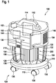
- a suction device 100 according to the invention is shown in a perspective view.
- the suction device 100 is designed as a centrifugal separator.
- the suction device 100 has a housing 102 which is detachably connected to a collecting container 104 and a filter element 106.
- the suction device 100 is essentially cylindrical in shape and extends along a longitudinal axis that represents a housing axis 110.
- the suction device 100 has a cyclone chamber 120 which, in the connected state, is at least partially delimited axially by the housing 102 and the collecting container 104 and radially by the collecting container 104 and the filter element 106.
- the collecting container 104 is advantageously at least partially transparent.
- the detachable connection of the housing 102 to the collecting container 104 takes place via at least one locking element 138.
- the locking element 138 is on the housing 102 arranged.
- the locking element 138 is movably connected to the housing 102.
- the locking element 138 is designed for a non-positive and positive connection of the housing 102 to the collecting container 104.
- the housing 102 has two locking elements 138 which are arranged opposite one another on the housing 102, see in this regard Fig. 2 .
- a suction device holding element 112 is arranged on an upper side of the housing 102.
- the suction device holding element 112 is attached to the top of the housing 102.
- the suction device holding element 112 is designed as a carrying handle and has a handle area 114.
- the grip area 114 is designed to be enclosed by one hand of a user of the suction device 100.
- the suction device 100 can advantageously be carried during use or for transport.
- a suction device movement unit 134 is attached to the housing 102.
- the suction device 100 is designed as a mobile suction device.
- the suction device movement unit 134 has at least one suction device movement element 136.
- the suction device movement unit 134 has four suction device movement elements 136, the suction device movement elements 136 being embodied as rollers, for example.
- the suction device 100 has a suction device operating unit 130 with at least one suction device operating element 132.
- the suction device operating element 132 is designed to be operated by the user and to generate switching signals. The switching signals then control a suction device drive 140.
- the suction device drive 140 has an electric motor 142 and at least one electronics unit.
- the suction device operating element 132 can be arranged on one side of the housing 102.
- the suction device operating element 132 is designed, for example, as a main switch for switching the suction device 100 on and off.
- the electric motor 142 drives at least one fan unit in order to generate the air flow 150.
- the fan unit is not shown in more detail here and can, for example, be designed as a radial or axial fan.
- the electric motor 142 is supplied with electrical energy by a suction device energy supply unit 144.
- the suction device 100 is preferably a battery-operated suction device, so that the suction device energy supply unit 144 has at least one rechargeable battery.
- the battery is advantageously designed as a handheld power tool battery pack. The provision of the electrical energy for the electric motor 142 by the suction device energy supply unit 144 can thus be made possible.
- the housing 102 has an air inlet 152, see also Fig. 2 .
- the housing 102 further comprises an air outlet 154, via which the air stream 150 can leave the housing 102.
- the air inlet 152 and the air outlet 154 of the suction device 100 can be arranged on opposite sides of the housing 102.
- the suction device 100 is designed to collect and separate material particles and / or liquids from the air stream 150.
- the air flow 150 is generated by the electric motor 142.
- the air inlet 152 is used to enable the air flow 150 to enter the housing 102.
- the air stream 150 is guided into the collecting container 104 by means of a first air channel 156, see also Fig. 2 .
- the collecting container 104 collects the substance particles and / or the liquids. As described above, the collecting container 104 is detachably connected to the housing 102 of the suction device 100.
- the air stream 150 is passed over the filter element 106, see also Fig. 2 . Furthermore, the air flow 150 is guided out of the housing 102 via the air outlet 154 via a second air duct. The second air duct is not shown in detail here.
- the cyclone chamber 120 receives the filter element 106, so that the filter element 106 is arranged in the cyclone chamber 120 in the connected state. Furthermore, the filter element 106 is detachably connected to the housing 102.
- the filter element 106 can be detachably connected to the housing 102 of the suction device 100 via a bayonet connection.
- the filter element 106 at least partially delimits the cyclone chamber 120.
- the filter element 106 is shaped as a pleated filter.
- the substance and / or fluid particles are separated from the air stream 150 via a centrifugal separation mechanism.
- the air stream 150 is guided tangentially into the cyclone chamber 120 at least in some areas.
- the air flow 150 is guided within the cyclone chamber 120 at least in some areas on a circular path.
- the air stream 150 is guided around the filter element 106 within the cyclone chamber 120.
- the cyclone chamber 120 is shaped at least in sections as a hollow cylinder. An outer diameter of the hollow cylinder is taken from the collecting container 104 and an inner diameter of the hollow cylinder formed by the filter element 106.
- the suction device 100 further comprises at least one positioning device 200 within the cyclone chamber 120 for positioning at least one collecting element 108 within the cyclone chamber 120.
- the positioning device 200 is designed to position the collecting element 108 within the cyclone chamber 120.
- the positioning device 200 can additionally center the collecting element 108, see also Fig. 2 .
- the collecting element 108 can be shaped as a collecting bag or as a disposal bag or alternatively as a collecting bin.
- the collecting container 104 is designed to receive the collecting element 108.
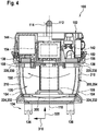
- a longitudinal section through the suction device 100 with a first embodiment 202 of the positioning device 200 is shown.
- the positioning device 200 is connected to the housing 102.
- the positioning device 200 is arranged in the radial direction 310 between the filter element 106 and the collecting container 104 in relation to the housing axis 110.
- the housing 102 of the suction device 100 is essentially cylindrical.
- the longitudinal axis of the housing 102 here represents the housing axis 110.
- the positioning device 200 is arranged between the filter element 106 and the collecting container 104, leading away from the housing axis 110 in the radial direction 310.
- the positioning device 200 is arranged coaxially between the filter element 106 and the collecting container 104 relative to the housing axis 110.
- the filter element 106 is arranged on the housing axis 110.
- the collecting container 104 is designed to at least partially receive the positioning device 200.
- the collecting container 104 can receive the positioning device 200 in a non-positive and / or positive manner.
- the collecting container 104 encloses the positioning device 200 at least partially in the circumferential direction 300.
- the circumferential direction 310 is here relative to the housing axis 110.
- the positioning device 200 is arranged on the housing 102.
- the positioning device 200 is essentially firmly connected to the housing 102 by means of fastening elements.
- the fastening elements can be shaped as screws or nuts.
- the positioning device 200 is formed for the arrangement of the collecting element 108 on an inner surface of the collecting container 104.
- the positioning device 200 can arrange the collecting element 108 on the inner surface of the collecting container 104 during operation of the suction device 100.
- the positioning device 200 releasably arranges the collecting element 108 on the inner surface of the collecting container 104.
- the positioning device 200 presses, presses or clamps the collecting element 108 onto the inner surface of the collecting container 104.
- the radial and / or axial force points outwards, away from the housing axis 110 , directed.
- the positioning device 200 is shaped in such a way that the circular path of the air flow 150 within the cyclone chamber 120 around the filter element 106 can be formed in a substantially reduced manner.
- the positioning device 200 is also designed to hold the collecting element 108.
- the positioning device 200 can hold the collecting element 108 in such a way that it is easier to remove the collecting element 108 from the collecting container 104.
- the positioning device 200 is additionally designed to exert at least one further radial and / or axial force relative to the housing axis 110 on the collecting element 108. In this way, the positioning device 200 can, for example, tension, press or clamp the collecting element 108 in the radial and / or axial direction 310, 320.
- the positioning device 200 comprises a substantially circular cross section.
- the positioning device 200 comprises a pitch circle diameter 330 in the range from 200 mm to 340 mm.
- the positioning device 200 comprises a cooling circle diameter 340 in the range from 210 mm to 350 mm.
- the positioning device 200 comprises a plurality of positioning elements 210.
- the positioning elements 210 are designed to position the collecting element 108 on the inner surface of the collecting container 104.
- the positioning elements 210 are designed to position the collecting element 108 with the aid of the radial and / or axial force on the inner surface of the collecting container 104.
- the positioning elements 210 are, for example, rod-shaped with essentially one free, rolled and rounded end.
- the positioning elements 210 each have an axial length 212 in the range from 100 mm to 210 mm.
- the positioning device 200 further comprises a frame element 230 for stabilizing the positioning device 200 within the collecting container 104.
- the positioning elements 210 are arranged on the frame element 230.
- the positioning elements 210 can be connected to the frame element 230 in a non-positive, positive and / or cohesive manner.
- the positioning elements 210 and the frame element 230 are formed in one piece.
- the frame element 230 arranges the positioning elements 210 at an angular distance 216 from one another in a range of 10 ° to 120 ° in each case.
- the positioning elements 210 are arranged uniformly in the circumferential direction 300 to the housing axis 110.
- the positioning elements 210 are arranged in such a way that they are arranged essentially in the shape of a cylinder jacket. Due to their arrangement on the connecting element 220, the positioning elements 210 form a type of cylinder jacket.
- the cylinder jacket has a pitch circle diameter 332 in the range from 200 mm to 340 mm.
- the cylinder jacket has a cylinder height 214 in the range from 100 mm to 210 mm.
- the positioning device 200 further comprises at least one connecting element 220 for connecting the positioning device 200 to the housing 102.
- the connecting element 220 is essentially firmly attached to the housing 102 by means of attachment elements.
- the connecting element 220 can comprise at least one receiving element 222, which is designed to receive the fastening elements.
- the positioning device 200 can be connected to the housing 102 with the aid of the fastening elements and the receiving elements 222.
- the receiving element 222 is formed as a receiving opening and the fastening element is formed as a screw.
- six receiving openings are provided here, the fastening elements not being shown in detail.
- the positioning elements 210, the frame element 230 and the connecting element 220 are formed in one piece.
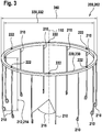
- a longitudinal section through the suction device 100 with a second embodiment 204 of the positioning device 200 is shown.
- the positioning device 200 is detachably connected to the housing 102 and is designed in the manner of a basket.
- the positioning device 200 has the frame element 230 for the uniform arrangement of the positioning elements 210 in the circumferential direction 300, as well as a further frame element 232 for stabilizing the positioning device 200 in the collecting container 104.
- the frame element 230 and the further frame element 232 are each annular in this embodiment and are connected to one another by the positioning elements 210.
- the collecting container 104 can receive the second embodiment 204 of the positioning device 200 in a form-fitting manner.
- the positioning device 200 in this embodiment has the connecting element 220 for the detachable connection to the housing 102 and the collecting container 104, as well as a further connecting element 224 for the detachable connection to the collecting container 104 and / or the filter element 106.
- the frame element 230 forms the connecting element 220.
- the further frame element 232 also forms the further connecting element 224 here.
- the connecting element 220, the further connecting element 224, the frame element 230, the further frame element 232 and the positioning elements 210 are formed in one piece.
- the collecting element 108 is arranged in the radial direction 310 between the collecting container 104 and the positioning device 200.
- the positioning device 200 holds the collecting element 108 on the inner surface of the collecting container 104.
Landscapes
- Engineering & Computer Science (AREA)
- Mechanical Engineering (AREA)
- Physics & Mathematics (AREA)
- Fluid Mechanics (AREA)
- Cyclones (AREA)
- Filters For Electric Vacuum Cleaners (AREA)
- Manipulator (AREA)
- Branching, Merging, And Special Transfer Between Conveyors (AREA)
- Massaging Devices (AREA)
- Filtering Of Dispersed Particles In Gases (AREA)
Applications Claiming Priority (1)
| Application Number | Priority Date | Filing Date | Title |
|---|---|---|---|
| DE102019206568.6A DE102019206568A1 (de) | 2019-05-08 | 2019-05-08 | Sauggerät |
Publications (2)
| Publication Number | Publication Date |
|---|---|
| EP3735885A1 true EP3735885A1 (fr) | 2020-11-11 |
| EP3735885B1 EP3735885B1 (fr) | 2023-06-07 |
Family
ID=70390839
Family Applications (1)
| Application Number | Title | Priority Date | Filing Date |
|---|---|---|---|
| EP20170552.2A Active EP3735885B1 (fr) | 2019-05-08 | 2020-04-21 | Appareil d'aspiration |
Country Status (5)
| Country | Link |
|---|---|
| US (1) | US11406237B2 (fr) |
| EP (1) | EP3735885B1 (fr) |
| CN (1) | CN111904331A (fr) |
| DE (1) | DE102019206568A1 (fr) |
| ES (1) | ES2953323T3 (fr) |
Cited By (1)
| Publication number | Priority date | Publication date | Assignee | Title |
|---|---|---|---|---|
| EP4696210A1 (fr) * | 2024-08-16 | 2026-02-18 | Vorwerk & Co. Interholding GmbH | Unité de séparateur dotée d'une unité de déchets remplaçable, système d'aspirateur et procédé |
Citations (4)
| Publication number | Priority date | Publication date | Assignee | Title |
|---|---|---|---|---|
| EP1428617A1 (fr) * | 2002-12-09 | 2004-06-16 | Black & Decker Inc. | Rabot |
| EP2721985A2 (fr) * | 2011-06-15 | 2014-04-23 | Cho, Hyoung-Kwon | Dispositif pour raccorder un sac d'aspirateur |
| CN106037583A (zh) * | 2016-08-10 | 2016-10-26 | 天佑电器(苏州)有限公司 | 过滤袋安装结构及具有该过滤袋安装结构的吸尘器 |
| DE102016224105A1 (de) | 2016-12-05 | 2018-06-07 | Robert Bosch Gmbh | Saugvorrichtung |
Family Cites Families (6)
| Publication number | Priority date | Publication date | Assignee | Title |
|---|---|---|---|---|
| US5090976A (en) * | 1990-09-21 | 1992-02-25 | Notetry Limited | Dual cyclonic vacuum cleaner with disposable liner |
| JP2003024826A (ja) * | 2001-07-12 | 2003-01-28 | Casle Kk | 回収袋付きサイクロン分離装置 |
| DE102005053632A1 (de) * | 2005-11-10 | 2007-05-16 | Stihl Ag & Co Kg Andreas | Handgeführtes Sauggerät |
| DE102005053620A1 (de) * | 2005-11-10 | 2007-05-16 | Stihl Ag & Co Kg Andreas | Handgeführtes Sauggerät |
| JP2009195488A (ja) * | 2008-02-21 | 2009-09-03 | Sanyo Electric Co Ltd | 電気掃除機 |
| CN208551653U (zh) * | 2017-10-31 | 2019-03-01 | 博世电动工具(中国)有限公司 | 吸尘器 |
-
2019
- 2019-05-08 DE DE102019206568.6A patent/DE102019206568A1/de not_active Withdrawn
-
2020
- 2020-04-21 EP EP20170552.2A patent/EP3735885B1/fr active Active
- 2020-04-21 ES ES20170552T patent/ES2953323T3/es active Active
- 2020-05-05 US US16/866,784 patent/US11406237B2/en active Active
- 2020-05-08 CN CN202010380502.7A patent/CN111904331A/zh active Pending
Patent Citations (4)
| Publication number | Priority date | Publication date | Assignee | Title |
|---|---|---|---|---|
| EP1428617A1 (fr) * | 2002-12-09 | 2004-06-16 | Black & Decker Inc. | Rabot |
| EP2721985A2 (fr) * | 2011-06-15 | 2014-04-23 | Cho, Hyoung-Kwon | Dispositif pour raccorder un sac d'aspirateur |
| CN106037583A (zh) * | 2016-08-10 | 2016-10-26 | 天佑电器(苏州)有限公司 | 过滤袋安装结构及具有该过滤袋安装结构的吸尘器 |
| DE102016224105A1 (de) | 2016-12-05 | 2018-06-07 | Robert Bosch Gmbh | Saugvorrichtung |
Cited By (1)
| Publication number | Priority date | Publication date | Assignee | Title |
|---|---|---|---|---|
| EP4696210A1 (fr) * | 2024-08-16 | 2026-02-18 | Vorwerk & Co. Interholding GmbH | Unité de séparateur dotée d'une unité de déchets remplaçable, système d'aspirateur et procédé |
Also Published As
| Publication number | Publication date |
|---|---|
| US11406237B2 (en) | 2022-08-09 |
| CN111904331A (zh) | 2020-11-10 |
| ES2953323T3 (es) | 2023-11-10 |
| EP3735885B1 (fr) | 2023-06-07 |
| DE102019206568A1 (de) | 2020-11-12 |
| US20200353484A1 (en) | 2020-11-12 |
Similar Documents
| Publication | Publication Date | Title |
|---|---|---|
| DE102013215792B4 (de) | Handwerkzeugmaschinenabsaugvorrichtung | |
| DE102014200663A1 (de) | Akkubetriebener Handstaubsauger | |
| EP3357646A2 (fr) | Outil électrique à main pourvu de couvercle de protection contre la poussière | |
| EP3338611B1 (fr) | Dispositif d'aspiration | |
| EP3389941B1 (fr) | Couvercle de boîtier pour machine-outil portative | |
| DE102018216726A1 (de) | Staubabsaugvorrichtung | |
| EP0215476B1 (fr) | Meuleur rotatif avec dispositif d'aspiration de la poussière | |
| EP1731749B1 (fr) | Système de distribution de poussière | |
| EP3735885B1 (fr) | Appareil d'aspiration | |
| EP3735886B1 (fr) | Appareil d'aspiration | |
| EP2449932B1 (fr) | Aspirateur doté d'un dispositif de retenue de tuyau d'aspiration | |
| DE102011051938A1 (de) | Werkzeugaufnahmevorrichtung, Werkzeugaufnahmevorrichtung-Werkzeug-Kombination und Werkzeugmaschine | |
| EP3209464B1 (fr) | Machine-outil portative pourvue d'un porte-outil sds | |
| JPH06154566A (ja) | 膜体フィルタ除去ツール | |
| DE102010045702A1 (de) | Faserschneidvorrichtung | |
| EP2106327A1 (fr) | Machine-outil à main | |
| EP4231888B1 (fr) | Appareil d'aspiration | |
| DE102013220202B4 (de) | Absaugvorrichtung für eine Werkzeugmaschine | |
| DE102004025880B3 (de) | Absaugeinrichtung für Elektrohandwerkzeuggeräte | |
| DE102005062464A1 (de) | Absaugvorrichtung für eine Handwerkzeugmaschine | |
| EP3814054A1 (fr) | Bloc de meulage destiné à être utilisé manuellement ainsi que système comprenant un bloc de meulage et un article abrasif | |
| DE102020213229A1 (de) | Handschleifmaschine | |
| DE102021208079A1 (de) | Absaugadapter | |
| DE102016224100A1 (de) | Saugvorrichtung | |
| DE102016224161A1 (de) | Saugvorrichtung |
Legal Events
| Date | Code | Title | Description |
|---|---|---|---|
| PUAI | Public reference made under article 153(3) epc to a published international application that has entered the european phase |
Free format text: ORIGINAL CODE: 0009012 |
|
| STAA | Information on the status of an ep patent application or granted ep patent |
Free format text: STATUS: THE APPLICATION HAS BEEN PUBLISHED |
|
| AK | Designated contracting states |
Kind code of ref document: A1 Designated state(s): AL AT BE BG CH CY CZ DE DK EE ES FI FR GB GR HR HU IE IS IT LI LT LU LV MC MK MT NL NO PL PT RO RS SE SI SK SM TR |
|
| AX | Request for extension of the european patent |
Extension state: BA ME |
|
| STAA | Information on the status of an ep patent application or granted ep patent |
Free format text: STATUS: REQUEST FOR EXAMINATION WAS MADE |
|
| 17P | Request for examination filed |
Effective date: 20210511 |
|
| RBV | Designated contracting states (corrected) |
Designated state(s): AL AT BE BG CH CY CZ DE DK EE ES FI FR GB GR HR HU IE IS IT LI LT LU LV MC MK MT NL NO PL PT RO RS SE SI SK SM TR |
|
| GRAP | Despatch of communication of intention to grant a patent |
Free format text: ORIGINAL CODE: EPIDOSNIGR1 |
|
| STAA | Information on the status of an ep patent application or granted ep patent |
Free format text: STATUS: GRANT OF PATENT IS INTENDED |
|
| INTG | Intention to grant announced |
Effective date: 20230120 |
|
| GRAS | Grant fee paid |
Free format text: ORIGINAL CODE: EPIDOSNIGR3 |
|
| GRAA | (expected) grant |
Free format text: ORIGINAL CODE: 0009210 |
|
| STAA | Information on the status of an ep patent application or granted ep patent |
Free format text: STATUS: THE PATENT HAS BEEN GRANTED |
|
| AK | Designated contracting states |
Kind code of ref document: B1 Designated state(s): AL AT BE BG CH CY CZ DE DK EE ES FI FR GB GR HR HU IE IS IT LI LT LU LV MC MK MT NL NO PL PT RO RS SE SI SK SM TR |
|
| REG | Reference to a national code |
Ref country code: GB Ref legal event code: FG4D Free format text: NOT ENGLISH |
|
| REG | Reference to a national code |
Ref country code: CH Ref legal event code: EP Ref country code: AT Ref legal event code: REF Ref document number: 1572246 Country of ref document: AT Kind code of ref document: T Effective date: 20230615 Ref country code: DE Ref legal event code: R096 Ref document number: 502020003485 Country of ref document: DE |
|
| REG | Reference to a national code |
Ref country code: LT Ref legal event code: MG9D |
|
| REG | Reference to a national code |
Ref country code: NL Ref legal event code: MP Effective date: 20230607 |
|
| PG25 | Lapsed in a contracting state [announced via postgrant information from national office to epo] |
Ref country code: SE Free format text: LAPSE BECAUSE OF FAILURE TO SUBMIT A TRANSLATION OF THE DESCRIPTION OR TO PAY THE FEE WITHIN THE PRESCRIBED TIME-LIMIT Effective date: 20230607 Ref country code: NO Free format text: LAPSE BECAUSE OF FAILURE TO SUBMIT A TRANSLATION OF THE DESCRIPTION OR TO PAY THE FEE WITHIN THE PRESCRIBED TIME-LIMIT Effective date: 20230907 |
|
| REG | Reference to a national code |
Ref country code: ES Ref legal event code: FG2A Ref document number: 2953323 Country of ref document: ES Kind code of ref document: T3 Effective date: 20231110 |
|
| PG25 | Lapsed in a contracting state [announced via postgrant information from national office to epo] |
Ref country code: RS Free format text: LAPSE BECAUSE OF FAILURE TO SUBMIT A TRANSLATION OF THE DESCRIPTION OR TO PAY THE FEE WITHIN THE PRESCRIBED TIME-LIMIT Effective date: 20230607 Ref country code: NL Free format text: LAPSE BECAUSE OF FAILURE TO SUBMIT A TRANSLATION OF THE DESCRIPTION OR TO PAY THE FEE WITHIN THE PRESCRIBED TIME-LIMIT Effective date: 20230607 Ref country code: LV Free format text: LAPSE BECAUSE OF FAILURE TO SUBMIT A TRANSLATION OF THE DESCRIPTION OR TO PAY THE FEE WITHIN THE PRESCRIBED TIME-LIMIT Effective date: 20230607 Ref country code: LT Free format text: LAPSE BECAUSE OF FAILURE TO SUBMIT A TRANSLATION OF THE DESCRIPTION OR TO PAY THE FEE WITHIN THE PRESCRIBED TIME-LIMIT Effective date: 20230607 Ref country code: HR Free format text: LAPSE BECAUSE OF FAILURE TO SUBMIT A TRANSLATION OF THE DESCRIPTION OR TO PAY THE FEE WITHIN THE PRESCRIBED TIME-LIMIT Effective date: 20230607 Ref country code: GR Free format text: LAPSE BECAUSE OF FAILURE TO SUBMIT A TRANSLATION OF THE DESCRIPTION OR TO PAY THE FEE WITHIN THE PRESCRIBED TIME-LIMIT Effective date: 20230908 |
|
| PG25 | Lapsed in a contracting state [announced via postgrant information from national office to epo] |
Ref country code: FI Free format text: LAPSE BECAUSE OF FAILURE TO SUBMIT A TRANSLATION OF THE DESCRIPTION OR TO PAY THE FEE WITHIN THE PRESCRIBED TIME-LIMIT Effective date: 20230607 |
|
| PG25 | Lapsed in a contracting state [announced via postgrant information from national office to epo] |
Ref country code: SK Free format text: LAPSE BECAUSE OF FAILURE TO SUBMIT A TRANSLATION OF THE DESCRIPTION OR TO PAY THE FEE WITHIN THE PRESCRIBED TIME-LIMIT Effective date: 20230607 |
|
| PG25 | Lapsed in a contracting state [announced via postgrant information from national office to epo] |
Ref country code: IS Free format text: LAPSE BECAUSE OF FAILURE TO SUBMIT A TRANSLATION OF THE DESCRIPTION OR TO PAY THE FEE WITHIN THE PRESCRIBED TIME-LIMIT Effective date: 20231007 |
|
| PG25 | Lapsed in a contracting state [announced via postgrant information from national office to epo] |
Ref country code: SM Free format text: LAPSE BECAUSE OF FAILURE TO SUBMIT A TRANSLATION OF THE DESCRIPTION OR TO PAY THE FEE WITHIN THE PRESCRIBED TIME-LIMIT Effective date: 20230607 Ref country code: SK Free format text: LAPSE BECAUSE OF FAILURE TO SUBMIT A TRANSLATION OF THE DESCRIPTION OR TO PAY THE FEE WITHIN THE PRESCRIBED TIME-LIMIT Effective date: 20230607 Ref country code: RO Free format text: LAPSE BECAUSE OF FAILURE TO SUBMIT A TRANSLATION OF THE DESCRIPTION OR TO PAY THE FEE WITHIN THE PRESCRIBED TIME-LIMIT Effective date: 20230607 Ref country code: PT Free format text: LAPSE BECAUSE OF FAILURE TO SUBMIT A TRANSLATION OF THE DESCRIPTION OR TO PAY THE FEE WITHIN THE PRESCRIBED TIME-LIMIT Effective date: 20231009 Ref country code: IS Free format text: LAPSE BECAUSE OF FAILURE TO SUBMIT A TRANSLATION OF THE DESCRIPTION OR TO PAY THE FEE WITHIN THE PRESCRIBED TIME-LIMIT Effective date: 20231007 Ref country code: EE Free format text: LAPSE BECAUSE OF FAILURE TO SUBMIT A TRANSLATION OF THE DESCRIPTION OR TO PAY THE FEE WITHIN THE PRESCRIBED TIME-LIMIT Effective date: 20230607 Ref country code: CZ Free format text: LAPSE BECAUSE OF FAILURE TO SUBMIT A TRANSLATION OF THE DESCRIPTION OR TO PAY THE FEE WITHIN THE PRESCRIBED TIME-LIMIT Effective date: 20230607 |
|
| PG25 | Lapsed in a contracting state [announced via postgrant information from national office to epo] |
Ref country code: PL Free format text: LAPSE BECAUSE OF FAILURE TO SUBMIT A TRANSLATION OF THE DESCRIPTION OR TO PAY THE FEE WITHIN THE PRESCRIBED TIME-LIMIT Effective date: 20230607 |
|
| REG | Reference to a national code |
Ref country code: DE Ref legal event code: R097 Ref document number: 502020003485 Country of ref document: DE |
|
| PLBE | No opposition filed within time limit |
Free format text: ORIGINAL CODE: 0009261 |
|
| STAA | Information on the status of an ep patent application or granted ep patent |
Free format text: STATUS: NO OPPOSITION FILED WITHIN TIME LIMIT |
|
| PG25 | Lapsed in a contracting state [announced via postgrant information from national office to epo] |
Ref country code: DK Free format text: LAPSE BECAUSE OF FAILURE TO SUBMIT A TRANSLATION OF THE DESCRIPTION OR TO PAY THE FEE WITHIN THE PRESCRIBED TIME-LIMIT Effective date: 20230607 |
|
| PG25 | Lapsed in a contracting state [announced via postgrant information from national office to epo] |
Ref country code: SI Free format text: LAPSE BECAUSE OF FAILURE TO SUBMIT A TRANSLATION OF THE DESCRIPTION OR TO PAY THE FEE WITHIN THE PRESCRIBED TIME-LIMIT Effective date: 20230607 |
|
| 26N | No opposition filed |
Effective date: 20240308 |
|
| PG25 | Lapsed in a contracting state [announced via postgrant information from national office to epo] |
Ref country code: SI Free format text: LAPSE BECAUSE OF FAILURE TO SUBMIT A TRANSLATION OF THE DESCRIPTION OR TO PAY THE FEE WITHIN THE PRESCRIBED TIME-LIMIT Effective date: 20230607 |
|
| PGFP | Annual fee paid to national office [announced via postgrant information from national office to epo] |
Ref country code: ES Payment date: 20240517 Year of fee payment: 5 |
|
| PG25 | Lapsed in a contracting state [announced via postgrant information from national office to epo] |
Ref country code: BG Free format text: LAPSE BECAUSE OF FAILURE TO SUBMIT A TRANSLATION OF THE DESCRIPTION OR TO PAY THE FEE WITHIN THE PRESCRIBED TIME-LIMIT Effective date: 20230607 |
|
| PG25 | Lapsed in a contracting state [announced via postgrant information from national office to epo] |
Ref country code: MC Free format text: LAPSE BECAUSE OF FAILURE TO SUBMIT A TRANSLATION OF THE DESCRIPTION OR TO PAY THE FEE WITHIN THE PRESCRIBED TIME-LIMIT Effective date: 20230607 |
|
| PG25 | Lapsed in a contracting state [announced via postgrant information from national office to epo] |
Ref country code: MC Free format text: LAPSE BECAUSE OF FAILURE TO SUBMIT A TRANSLATION OF THE DESCRIPTION OR TO PAY THE FEE WITHIN THE PRESCRIBED TIME-LIMIT Effective date: 20230607 Ref country code: BG Free format text: LAPSE BECAUSE OF FAILURE TO SUBMIT A TRANSLATION OF THE DESCRIPTION OR TO PAY THE FEE WITHIN THE PRESCRIBED TIME-LIMIT Effective date: 20230607 |
|
| REG | Reference to a national code |
Ref country code: CH Ref legal event code: PL |
|
| PG25 | Lapsed in a contracting state [announced via postgrant information from national office to epo] |
Ref country code: LU Free format text: LAPSE BECAUSE OF NON-PAYMENT OF DUE FEES Effective date: 20240421 |
|
| REG | Reference to a national code |
Ref country code: BE Ref legal event code: MM Effective date: 20240430 |
|
| PG25 | Lapsed in a contracting state [announced via postgrant information from national office to epo] |
Ref country code: LU Free format text: LAPSE BECAUSE OF NON-PAYMENT OF DUE FEES Effective date: 20240421 |
|
| PG25 | Lapsed in a contracting state [announced via postgrant information from national office to epo] |
Ref country code: BE Free format text: LAPSE BECAUSE OF NON-PAYMENT OF DUE FEES Effective date: 20240430 |
|
| PG25 | Lapsed in a contracting state [announced via postgrant information from national office to epo] |
Ref country code: BE Free format text: LAPSE BECAUSE OF NON-PAYMENT OF DUE FEES Effective date: 20240430 Ref country code: CH Free format text: LAPSE BECAUSE OF NON-PAYMENT OF DUE FEES Effective date: 20240430 |
|
| PG25 | Lapsed in a contracting state [announced via postgrant information from national office to epo] |
Ref country code: IE Free format text: LAPSE BECAUSE OF NON-PAYMENT OF DUE FEES Effective date: 20240421 |
|
| PGFP | Annual fee paid to national office [announced via postgrant information from national office to epo] |
Ref country code: DE Payment date: 20250624 Year of fee payment: 6 |
|
| PGFP | Annual fee paid to national office [announced via postgrant information from national office to epo] |
Ref country code: IT Payment date: 20250430 Year of fee payment: 6 |
|
| PGFP | Annual fee paid to national office [announced via postgrant information from national office to epo] |
Ref country code: FR Payment date: 20250422 Year of fee payment: 6 |
|
| PGFP | Annual fee paid to national office [announced via postgrant information from national office to epo] |
Ref country code: AT Payment date: 20250721 Year of fee payment: 5 |
|
| PG25 | Lapsed in a contracting state [announced via postgrant information from national office to epo] |
Ref country code: CY Free format text: LAPSE BECAUSE OF FAILURE TO SUBMIT A TRANSLATION OF THE DESCRIPTION OR TO PAY THE FEE WITHIN THE PRESCRIBED TIME-LIMIT; INVALID AB INITIO Effective date: 20200421 |
|
| PG25 | Lapsed in a contracting state [announced via postgrant information from national office to epo] |
Ref country code: HU Free format text: LAPSE BECAUSE OF FAILURE TO SUBMIT A TRANSLATION OF THE DESCRIPTION OR TO PAY THE FEE WITHIN THE PRESCRIBED TIME-LIMIT; INVALID AB INITIO Effective date: 20200421 |
|
| PGFP | Annual fee paid to national office [announced via postgrant information from national office to epo] |
Ref country code: GB Payment date: 20260324 Year of fee payment: 7 |