EP3735938A1 - Vorrichtung und verfahren zur reparatur von aortenklappeninsuffizienz - Google Patents
Vorrichtung und verfahren zur reparatur von aortenklappeninsuffizienz Download PDFInfo
- Publication number
- EP3735938A1 EP3735938A1 EP20178028.5A EP20178028A EP3735938A1 EP 3735938 A1 EP3735938 A1 EP 3735938A1 EP 20178028 A EP20178028 A EP 20178028A EP 3735938 A1 EP3735938 A1 EP 3735938A1
- Authority
- EP
- European Patent Office
- Prior art keywords
- leaflet
- support frame
- stent
- members
- support
- Prior art date
- Legal status (The legal status is an assumption and is not a legal conclusion. Google has not performed a legal analysis and makes no representation as to the accuracy of the status listed.)
- Granted
Links
Images
































Classifications
-
- A—HUMAN NECESSITIES
- A61—MEDICAL OR VETERINARY SCIENCE; HYGIENE
- A61F—FILTERS IMPLANTABLE INTO BLOOD VESSELS; PROSTHESES; DEVICES PROVIDING PATENCY TO, OR PREVENTING COLLAPSING OF, TUBULAR STRUCTURES OF THE BODY, e.g. STENTS; ORTHOPAEDIC, NURSING OR CONTRACEPTIVE DEVICES; FOMENTATION; TREATMENT OR PROTECTION OF EYES OR EARS; BANDAGES, DRESSINGS OR ABSORBENT PADS; FIRST-AID KITS
- A61F2/00—Filters implantable into blood vessels; Prostheses, i.e. artificial substitutes or replacements for parts of the body; Appliances for connecting them with the body; Devices providing patency to, or preventing collapsing of, tubular structures of the body, e.g. stents
- A61F2/02—Prostheses implantable into the body
- A61F2/24—Heart valves ; Vascular valves, e.g. venous valves; Heart implants, e.g. passive devices for improving the function of the native valve or the heart muscle; Transmyocardial revascularisation [TMR] devices; Valves implantable in the body
- A61F2/2442—Annuloplasty rings or inserts for correcting the valve shape; Implants for improving the function of a native heart valve
- A61F2/246—Devices for obstructing a leak through a native valve in a closed condition
-
- A—HUMAN NECESSITIES
- A61—MEDICAL OR VETERINARY SCIENCE; HYGIENE
- A61F—FILTERS IMPLANTABLE INTO BLOOD VESSELS; PROSTHESES; DEVICES PROVIDING PATENCY TO, OR PREVENTING COLLAPSING OF, TUBULAR STRUCTURES OF THE BODY, e.g. STENTS; ORTHOPAEDIC, NURSING OR CONTRACEPTIVE DEVICES; FOMENTATION; TREATMENT OR PROTECTION OF EYES OR EARS; BANDAGES, DRESSINGS OR ABSORBENT PADS; FIRST-AID KITS
- A61F2/00—Filters implantable into blood vessels; Prostheses, i.e. artificial substitutes or replacements for parts of the body; Appliances for connecting them with the body; Devices providing patency to, or preventing collapsing of, tubular structures of the body, e.g. stents
- A61F2/02—Prostheses implantable into the body
- A61F2/24—Heart valves ; Vascular valves, e.g. venous valves; Heart implants, e.g. passive devices for improving the function of the native valve or the heart muscle; Transmyocardial revascularisation [TMR] devices; Valves implantable in the body
- A61F2/2442—Annuloplasty rings or inserts for correcting the valve shape; Implants for improving the function of a native heart valve
- A61F2/2466—Delivery devices therefor
-
- A—HUMAN NECESSITIES
- A61—MEDICAL OR VETERINARY SCIENCE; HYGIENE
- A61F—FILTERS IMPLANTABLE INTO BLOOD VESSELS; PROSTHESES; DEVICES PROVIDING PATENCY TO, OR PREVENTING COLLAPSING OF, TUBULAR STRUCTURES OF THE BODY, e.g. STENTS; ORTHOPAEDIC, NURSING OR CONTRACEPTIVE DEVICES; FOMENTATION; TREATMENT OR PROTECTION OF EYES OR EARS; BANDAGES, DRESSINGS OR ABSORBENT PADS; FIRST-AID KITS
- A61F2/00—Filters implantable into blood vessels; Prostheses, i.e. artificial substitutes or replacements for parts of the body; Appliances for connecting them with the body; Devices providing patency to, or preventing collapsing of, tubular structures of the body, e.g. stents
- A61F2/02—Prostheses implantable into the body
- A61F2/04—Hollow or tubular parts of organs, e.g. bladders, tracheae, bronchi or bile ducts
- A61F2/06—Blood vessels
- A61F2/07—Stent-grafts
-
- A—HUMAN NECESSITIES
- A61—MEDICAL OR VETERINARY SCIENCE; HYGIENE
- A61F—FILTERS IMPLANTABLE INTO BLOOD VESSELS; PROSTHESES; DEVICES PROVIDING PATENCY TO, OR PREVENTING COLLAPSING OF, TUBULAR STRUCTURES OF THE BODY, e.g. STENTS; ORTHOPAEDIC, NURSING OR CONTRACEPTIVE DEVICES; FOMENTATION; TREATMENT OR PROTECTION OF EYES OR EARS; BANDAGES, DRESSINGS OR ABSORBENT PADS; FIRST-AID KITS
- A61F2/00—Filters implantable into blood vessels; Prostheses, i.e. artificial substitutes or replacements for parts of the body; Appliances for connecting them with the body; Devices providing patency to, or preventing collapsing of, tubular structures of the body, e.g. stents
- A61F2/02—Prostheses implantable into the body
- A61F2/24—Heart valves ; Vascular valves, e.g. venous valves; Heart implants, e.g. passive devices for improving the function of the native valve or the heart muscle; Transmyocardial revascularisation [TMR] devices; Valves implantable in the body
- A61F2/2409—Support rings therefor, e.g. for connecting valves to tissue
-
- A—HUMAN NECESSITIES
- A61—MEDICAL OR VETERINARY SCIENCE; HYGIENE
- A61F—FILTERS IMPLANTABLE INTO BLOOD VESSELS; PROSTHESES; DEVICES PROVIDING PATENCY TO, OR PREVENTING COLLAPSING OF, TUBULAR STRUCTURES OF THE BODY, e.g. STENTS; ORTHOPAEDIC, NURSING OR CONTRACEPTIVE DEVICES; FOMENTATION; TREATMENT OR PROTECTION OF EYES OR EARS; BANDAGES, DRESSINGS OR ABSORBENT PADS; FIRST-AID KITS
- A61F2/00—Filters implantable into blood vessels; Prostheses, i.e. artificial substitutes or replacements for parts of the body; Appliances for connecting them with the body; Devices providing patency to, or preventing collapsing of, tubular structures of the body, e.g. stents
- A61F2/02—Prostheses implantable into the body
- A61F2/24—Heart valves ; Vascular valves, e.g. venous valves; Heart implants, e.g. passive devices for improving the function of the native valve or the heart muscle; Transmyocardial revascularisation [TMR] devices; Valves implantable in the body
- A61F2/2412—Heart valves ; Vascular valves, e.g. venous valves; Heart implants, e.g. passive devices for improving the function of the native valve or the heart muscle; Transmyocardial revascularisation [TMR] devices; Valves implantable in the body with soft flexible valve members, e.g. tissue valves shaped like natural valves
- A61F2/2418—Scaffolds therefor, e.g. support stents
-
- A—HUMAN NECESSITIES
- A61—MEDICAL OR VETERINARY SCIENCE; HYGIENE
- A61F—FILTERS IMPLANTABLE INTO BLOOD VESSELS; PROSTHESES; DEVICES PROVIDING PATENCY TO, OR PREVENTING COLLAPSING OF, TUBULAR STRUCTURES OF THE BODY, e.g. STENTS; ORTHOPAEDIC, NURSING OR CONTRACEPTIVE DEVICES; FOMENTATION; TREATMENT OR PROTECTION OF EYES OR EARS; BANDAGES, DRESSINGS OR ABSORBENT PADS; FIRST-AID KITS
- A61F2/00—Filters implantable into blood vessels; Prostheses, i.e. artificial substitutes or replacements for parts of the body; Appliances for connecting them with the body; Devices providing patency to, or preventing collapsing of, tubular structures of the body, e.g. stents
- A61F2/02—Prostheses implantable into the body
- A61F2/24—Heart valves ; Vascular valves, e.g. venous valves; Heart implants, e.g. passive devices for improving the function of the native valve or the heart muscle; Transmyocardial revascularisation [TMR] devices; Valves implantable in the body
- A61F2/2427—Devices for manipulating or deploying heart valves during implantation
-
- A—HUMAN NECESSITIES
- A61—MEDICAL OR VETERINARY SCIENCE; HYGIENE
- A61F—FILTERS IMPLANTABLE INTO BLOOD VESSELS; PROSTHESES; DEVICES PROVIDING PATENCY TO, OR PREVENTING COLLAPSING OF, TUBULAR STRUCTURES OF THE BODY, e.g. STENTS; ORTHOPAEDIC, NURSING OR CONTRACEPTIVE DEVICES; FOMENTATION; TREATMENT OR PROTECTION OF EYES OR EARS; BANDAGES, DRESSINGS OR ABSORBENT PADS; FIRST-AID KITS
- A61F2/00—Filters implantable into blood vessels; Prostheses, i.e. artificial substitutes or replacements for parts of the body; Appliances for connecting them with the body; Devices providing patency to, or preventing collapsing of, tubular structures of the body, e.g. stents
- A61F2/02—Prostheses implantable into the body
- A61F2/24—Heart valves ; Vascular valves, e.g. venous valves; Heart implants, e.g. passive devices for improving the function of the native valve or the heart muscle; Transmyocardial revascularisation [TMR] devices; Valves implantable in the body
- A61F2/2427—Devices for manipulating or deploying heart valves during implantation
- A61F2/2436—Deployment by retracting a sheath
-
- A—HUMAN NECESSITIES
- A61—MEDICAL OR VETERINARY SCIENCE; HYGIENE
- A61F—FILTERS IMPLANTABLE INTO BLOOD VESSELS; PROSTHESES; DEVICES PROVIDING PATENCY TO, OR PREVENTING COLLAPSING OF, TUBULAR STRUCTURES OF THE BODY, e.g. STENTS; ORTHOPAEDIC, NURSING OR CONTRACEPTIVE DEVICES; FOMENTATION; TREATMENT OR PROTECTION OF EYES OR EARS; BANDAGES, DRESSINGS OR ABSORBENT PADS; FIRST-AID KITS
- A61F2/00—Filters implantable into blood vessels; Prostheses, i.e. artificial substitutes or replacements for parts of the body; Appliances for connecting them with the body; Devices providing patency to, or preventing collapsing of, tubular structures of the body, e.g. stents
- A61F2/02—Prostheses implantable into the body
- A61F2/24—Heart valves ; Vascular valves, e.g. venous valves; Heart implants, e.g. passive devices for improving the function of the native valve or the heart muscle; Transmyocardial revascularisation [TMR] devices; Valves implantable in the body
- A61F2/2442—Annuloplasty rings or inserts for correcting the valve shape; Implants for improving the function of a native heart valve
-
- A—HUMAN NECESSITIES
- A61—MEDICAL OR VETERINARY SCIENCE; HYGIENE
- A61F—FILTERS IMPLANTABLE INTO BLOOD VESSELS; PROSTHESES; DEVICES PROVIDING PATENCY TO, OR PREVENTING COLLAPSING OF, TUBULAR STRUCTURES OF THE BODY, e.g. STENTS; ORTHOPAEDIC, NURSING OR CONTRACEPTIVE DEVICES; FOMENTATION; TREATMENT OR PROTECTION OF EYES OR EARS; BANDAGES, DRESSINGS OR ABSORBENT PADS; FIRST-AID KITS
- A61F2/00—Filters implantable into blood vessels; Prostheses, i.e. artificial substitutes or replacements for parts of the body; Appliances for connecting them with the body; Devices providing patency to, or preventing collapsing of, tubular structures of the body, e.g. stents
- A61F2/02—Prostheses implantable into the body
- A61F2/24—Heart valves ; Vascular valves, e.g. venous valves; Heart implants, e.g. passive devices for improving the function of the native valve or the heart muscle; Transmyocardial revascularisation [TMR] devices; Valves implantable in the body
- A61F2/2442—Annuloplasty rings or inserts for correcting the valve shape; Implants for improving the function of a native heart valve
- A61F2/2454—Means for preventing inversion of the valve leaflets, e.g. chordae tendineae prostheses
-
- A—HUMAN NECESSITIES
- A61—MEDICAL OR VETERINARY SCIENCE; HYGIENE
- A61F—FILTERS IMPLANTABLE INTO BLOOD VESSELS; PROSTHESES; DEVICES PROVIDING PATENCY TO, OR PREVENTING COLLAPSING OF, TUBULAR STRUCTURES OF THE BODY, e.g. STENTS; ORTHOPAEDIC, NURSING OR CONTRACEPTIVE DEVICES; FOMENTATION; TREATMENT OR PROTECTION OF EYES OR EARS; BANDAGES, DRESSINGS OR ABSORBENT PADS; FIRST-AID KITS
- A61F2/00—Filters implantable into blood vessels; Prostheses, i.e. artificial substitutes or replacements for parts of the body; Appliances for connecting them with the body; Devices providing patency to, or preventing collapsing of, tubular structures of the body, e.g. stents
- A61F2/82—Devices providing patency to, or preventing collapsing of, tubular structures of the body, e.g. stents
- A61F2/86—Stents in a form characterised by the wire-like elements; Stents in the form characterised by a net-like or mesh-like structure
- A61F2/88—Stents in a form characterised by the wire-like elements; Stents in the form characterised by a net-like or mesh-like structure the wire-like elements formed as helical or spiral coils
-
- A—HUMAN NECESSITIES
- A61—MEDICAL OR VETERINARY SCIENCE; HYGIENE
- A61F—FILTERS IMPLANTABLE INTO BLOOD VESSELS; PROSTHESES; DEVICES PROVIDING PATENCY TO, OR PREVENTING COLLAPSING OF, TUBULAR STRUCTURES OF THE BODY, e.g. STENTS; ORTHOPAEDIC, NURSING OR CONTRACEPTIVE DEVICES; FOMENTATION; TREATMENT OR PROTECTION OF EYES OR EARS; BANDAGES, DRESSINGS OR ABSORBENT PADS; FIRST-AID KITS
- A61F2/00—Filters implantable into blood vessels; Prostheses, i.e. artificial substitutes or replacements for parts of the body; Appliances for connecting them with the body; Devices providing patency to, or preventing collapsing of, tubular structures of the body, e.g. stents
- A61F2/82—Devices providing patency to, or preventing collapsing of, tubular structures of the body, e.g. stents
- A61F2/86—Stents in a form characterised by the wire-like elements; Stents in the form characterised by a net-like or mesh-like structure
- A61F2/90—Stents in a form characterised by the wire-like elements; Stents in the form characterised by a net-like or mesh-like structure characterised by a net-like or mesh-like structure
- A61F2/91—Stents in a form characterised by the wire-like elements; Stents in the form characterised by a net-like or mesh-like structure characterised by a net-like or mesh-like structure made from perforated sheets or tubes, e.g. perforated by laser cuts or etched holes
-
- A—HUMAN NECESSITIES
- A61—MEDICAL OR VETERINARY SCIENCE; HYGIENE
- A61F—FILTERS IMPLANTABLE INTO BLOOD VESSELS; PROSTHESES; DEVICES PROVIDING PATENCY TO, OR PREVENTING COLLAPSING OF, TUBULAR STRUCTURES OF THE BODY, e.g. STENTS; ORTHOPAEDIC, NURSING OR CONTRACEPTIVE DEVICES; FOMENTATION; TREATMENT OR PROTECTION OF EYES OR EARS; BANDAGES, DRESSINGS OR ABSORBENT PADS; FIRST-AID KITS
- A61F2/00—Filters implantable into blood vessels; Prostheses, i.e. artificial substitutes or replacements for parts of the body; Appliances for connecting them with the body; Devices providing patency to, or preventing collapsing of, tubular structures of the body, e.g. stents
- A61F2/95—Instruments specially adapted for placement or removal of stents or stent-grafts
- A61F2/958—Inflatable balloons for placing stents or stent-grafts
-
- A—HUMAN NECESSITIES
- A61—MEDICAL OR VETERINARY SCIENCE; HYGIENE
- A61F—FILTERS IMPLANTABLE INTO BLOOD VESSELS; PROSTHESES; DEVICES PROVIDING PATENCY TO, OR PREVENTING COLLAPSING OF, TUBULAR STRUCTURES OF THE BODY, e.g. STENTS; ORTHOPAEDIC, NURSING OR CONTRACEPTIVE DEVICES; FOMENTATION; TREATMENT OR PROTECTION OF EYES OR EARS; BANDAGES, DRESSINGS OR ABSORBENT PADS; FIRST-AID KITS
- A61F2/00—Filters implantable into blood vessels; Prostheses, i.e. artificial substitutes or replacements for parts of the body; Appliances for connecting them with the body; Devices providing patency to, or preventing collapsing of, tubular structures of the body, e.g. stents
- A61F2/02—Prostheses implantable into the body
- A61F2/04—Hollow or tubular parts of organs, e.g. bladders, tracheae, bronchi or bile ducts
- A61F2/06—Blood vessels
- A61F2/07—Stent-grafts
- A61F2002/077—Stent-grafts having means to fill the space between stent-graft and aneurysm wall, e.g. a sleeve
-
- A—HUMAN NECESSITIES
- A61—MEDICAL OR VETERINARY SCIENCE; HYGIENE
- A61F—FILTERS IMPLANTABLE INTO BLOOD VESSELS; PROSTHESES; DEVICES PROVIDING PATENCY TO, OR PREVENTING COLLAPSING OF, TUBULAR STRUCTURES OF THE BODY, e.g. STENTS; ORTHOPAEDIC, NURSING OR CONTRACEPTIVE DEVICES; FOMENTATION; TREATMENT OR PROTECTION OF EYES OR EARS; BANDAGES, DRESSINGS OR ABSORBENT PADS; FIRST-AID KITS
- A61F2/00—Filters implantable into blood vessels; Prostheses, i.e. artificial substitutes or replacements for parts of the body; Appliances for connecting them with the body; Devices providing patency to, or preventing collapsing of, tubular structures of the body, e.g. stents
- A61F2/82—Devices providing patency to, or preventing collapsing of, tubular structures of the body, e.g. stents
- A61F2002/825—Devices providing patency to, or preventing collapsing of, tubular structures of the body, e.g. stents having longitudinal struts
-
- A—HUMAN NECESSITIES
- A61—MEDICAL OR VETERINARY SCIENCE; HYGIENE
- A61F—FILTERS IMPLANTABLE INTO BLOOD VESSELS; PROSTHESES; DEVICES PROVIDING PATENCY TO, OR PREVENTING COLLAPSING OF, TUBULAR STRUCTURES OF THE BODY, e.g. STENTS; ORTHOPAEDIC, NURSING OR CONTRACEPTIVE DEVICES; FOMENTATION; TREATMENT OR PROTECTION OF EYES OR EARS; BANDAGES, DRESSINGS OR ABSORBENT PADS; FIRST-AID KITS
- A61F2210/00—Particular material properties of prostheses classified in groups A61F2/00 - A61F2/26 or A61F2/82 or A61F9/00 or A61F11/00 or subgroups thereof
- A61F2210/0061—Particular material properties of prostheses classified in groups A61F2/00 - A61F2/26 or A61F2/82 or A61F9/00 or A61F11/00 or subgroups thereof swellable
-
- A—HUMAN NECESSITIES
- A61—MEDICAL OR VETERINARY SCIENCE; HYGIENE
- A61F—FILTERS IMPLANTABLE INTO BLOOD VESSELS; PROSTHESES; DEVICES PROVIDING PATENCY TO, OR PREVENTING COLLAPSING OF, TUBULAR STRUCTURES OF THE BODY, e.g. STENTS; ORTHOPAEDIC, NURSING OR CONTRACEPTIVE DEVICES; FOMENTATION; TREATMENT OR PROTECTION OF EYES OR EARS; BANDAGES, DRESSINGS OR ABSORBENT PADS; FIRST-AID KITS
- A61F2220/00—Fixations or connections for prostheses classified in groups A61F2/00 - A61F2/26 or A61F2/82 or A61F9/00 or A61F11/00 or subgroups thereof
- A61F2220/0008—Fixation appliances for connecting prostheses to the body
- A61F2220/0016—Fixation appliances for connecting prostheses to the body with sharp anchoring protrusions, e.g. barbs, pins, spikes
-
- A—HUMAN NECESSITIES
- A61—MEDICAL OR VETERINARY SCIENCE; HYGIENE
- A61F—FILTERS IMPLANTABLE INTO BLOOD VESSELS; PROSTHESES; DEVICES PROVIDING PATENCY TO, OR PREVENTING COLLAPSING OF, TUBULAR STRUCTURES OF THE BODY, e.g. STENTS; ORTHOPAEDIC, NURSING OR CONTRACEPTIVE DEVICES; FOMENTATION; TREATMENT OR PROTECTION OF EYES OR EARS; BANDAGES, DRESSINGS OR ABSORBENT PADS; FIRST-AID KITS
- A61F2230/00—Geometry of prostheses classified in groups A61F2/00 - A61F2/26 or A61F2/82 or A61F9/00 or A61F11/00 or subgroups thereof
- A61F2230/0002—Two-dimensional shapes, e.g. cross-sections
- A61F2230/0004—Rounded shapes, e.g. with rounded corners
- A61F2230/001—Figure-8-shaped, e.g. hourglass-shaped
-
- A—HUMAN NECESSITIES
- A61—MEDICAL OR VETERINARY SCIENCE; HYGIENE
- A61F—FILTERS IMPLANTABLE INTO BLOOD VESSELS; PROSTHESES; DEVICES PROVIDING PATENCY TO, OR PREVENTING COLLAPSING OF, TUBULAR STRUCTURES OF THE BODY, e.g. STENTS; ORTHOPAEDIC, NURSING OR CONTRACEPTIVE DEVICES; FOMENTATION; TREATMENT OR PROTECTION OF EYES OR EARS; BANDAGES, DRESSINGS OR ABSORBENT PADS; FIRST-AID KITS
- A61F2230/00—Geometry of prostheses classified in groups A61F2/00 - A61F2/26 or A61F2/82 or A61F9/00 or A61F11/00 or subgroups thereof
- A61F2230/0063—Three-dimensional shapes
- A61F2230/0065—Three-dimensional shapes toroidal, e.g. ring-shaped, doughnut-shaped
-
- A—HUMAN NECESSITIES
- A61—MEDICAL OR VETERINARY SCIENCE; HYGIENE
- A61F—FILTERS IMPLANTABLE INTO BLOOD VESSELS; PROSTHESES; DEVICES PROVIDING PATENCY TO, OR PREVENTING COLLAPSING OF, TUBULAR STRUCTURES OF THE BODY, e.g. STENTS; ORTHOPAEDIC, NURSING OR CONTRACEPTIVE DEVICES; FOMENTATION; TREATMENT OR PROTECTION OF EYES OR EARS; BANDAGES, DRESSINGS OR ABSORBENT PADS; FIRST-AID KITS
- A61F2230/00—Geometry of prostheses classified in groups A61F2/00 - A61F2/26 or A61F2/82 or A61F9/00 or A61F11/00 or subgroups thereof
- A61F2230/0063—Three-dimensional shapes
- A61F2230/0091—Three-dimensional shapes helically-coiled or spirally-coiled, i.e. having a 2-D spiral cross-section
-
- A—HUMAN NECESSITIES
- A61—MEDICAL OR VETERINARY SCIENCE; HYGIENE
- A61F—FILTERS IMPLANTABLE INTO BLOOD VESSELS; PROSTHESES; DEVICES PROVIDING PATENCY TO, OR PREVENTING COLLAPSING OF, TUBULAR STRUCTURES OF THE BODY, e.g. STENTS; ORTHOPAEDIC, NURSING OR CONTRACEPTIVE DEVICES; FOMENTATION; TREATMENT OR PROTECTION OF EYES OR EARS; BANDAGES, DRESSINGS OR ABSORBENT PADS; FIRST-AID KITS
- A61F2250/00—Special features of prostheses classified in groups A61F2/00 - A61F2/26 or A61F2/82 or A61F9/00 or A61F11/00 or subgroups thereof
- A61F2250/0004—Special features of prostheses classified in groups A61F2/00 - A61F2/26 or A61F2/82 or A61F9/00 or A61F11/00 or subgroups thereof adjustable
-
- A—HUMAN NECESSITIES
- A61—MEDICAL OR VETERINARY SCIENCE; HYGIENE
- A61F—FILTERS IMPLANTABLE INTO BLOOD VESSELS; PROSTHESES; DEVICES PROVIDING PATENCY TO, OR PREVENTING COLLAPSING OF, TUBULAR STRUCTURES OF THE BODY, e.g. STENTS; ORTHOPAEDIC, NURSING OR CONTRACEPTIVE DEVICES; FOMENTATION; TREATMENT OR PROTECTION OF EYES OR EARS; BANDAGES, DRESSINGS OR ABSORBENT PADS; FIRST-AID KITS
- A61F2250/00—Special features of prostheses classified in groups A61F2/00 - A61F2/26 or A61F2/82 or A61F9/00 or A61F11/00 or subgroups thereof
- A61F2250/0058—Additional features; Implant or prostheses properties not otherwise provided for
- A61F2250/006—Additional features; Implant or prostheses properties not otherwise provided for modular
- A61F2250/0063—Nested prosthetic parts
Definitions
- This application relates to methods, systems, and apparatus for safely replacing native heart valves with prosthetic heart valves.
- Prosthetic heart valves have been used for many years to treat cardiac valvular disorders.
- the native heart valves (such as the aortic, pulmonary, tricuspid and mitral valves) serve critical functions in assuring the forward flow of an adequate supply of blood through the cardiovascular system.
- These heart valves can be rendered less effective by congenital, inflammatory, or infectious conditions. Such conditions can eventually lead to serious cardiovascular compromise or death.
- the definitive treatment for such disorders was the surgical repair or replacement of the valve during open heart surgery.
- a transvascular technique for introducing and implanting a prosthetic heart valve using a flexible catheter in a manner that is less invasive than open heart surgery.
- a prosthetic valve is mounted in a crimped state on the end portion of a flexible catheter and advanced through a blood vessel of the patient until the valve reaches the implantation site.
- the valve at the catheter tip is then expanded to its functional size at the site of the defective native valve, such as by inflating a balloon on which the valve is mounted.
- the valve can have a resilient, self-expanding stent or frame that expands the valve to its functional size when it is advanced from a delivery sheath at the distal end of the catheter.
- Balloon-expandable valves are commonly used for treating heart valve stenosis, a condition in which the leaflets of a valve (e.g ., an aortic valve) become hardened with calcium.
- the hardened leaflets provide a good support structure on which the valve can be anchored within the valve annulus.
- the catheter balloon can apply sufficient expanding force to anchor the frame of the prosthetic valve to the surrounding calcified tissue.
- aortic insufficiency or aortic regurgitation
- aortic insufficiency occurs when an aortic valve does not close properly, allowing blood to flow back into the left ventricle.
- aortic insufficiency is a dilated aortic annulus, which prevents the aortic valve from closing tightly.
- the leaflets are usually too soft to provide sufficient support for a balloon-expandable prosthetic valve.
- the diameter of the aortic annulus may continue to vary over time, making it dangerous to install a prosthetic valve that is not reliably secured in the valve annulus. Mitral insufficiency (or mitral regurgitation) involves these same conditions but affects the mitral valve.
- Self-expanding prosthetic valves are sometimes used for replacing defective native valves with non-calcified leaflets.
- Self-expanding prosthetic valves however, suffer from a number of significant drawbacks. For example, once a self-expanding prosthetic valve is placed within the patient's defective heart valve (e.g ., the aorta or mitral valve), it continues to exert an outward force on the valve annulus. This continuous outward pressure can cause the valve annulus to dilate further, exacerbating the condition the valve was intended to treat. Additionally, when implanting a self-expanding valve, the outward biasing force of the valve's frame tends to cause the valve to be ejected very quickly from the distal end of a delivery sheath.
- the size of the prosthetic valve to be implanted into a patient can also be problematic when treating aortic or mitral insufficiency.
- the size of a prosthetic valve used to treat aortic or mitral insufficiency is typically larger than a prosthetic valve used to treat aortic or mitral stenosis. This larger valve size makes the delivery procedure much more difficult.
- prosthetic heart valves are retained by a stent or frame (i.e., a "pinch") placed in the aortic annulus prior to implantation of the valve, with the valve being configured to pinch the native valve leaflets against the frame.
- a stent or frame i.e., a "pinch”
- such frames typically require attachment to the delivery apparatus to hold the frame in place before and/or during implantation of the prosthetic heart valve. This requires that the frame delivery apparatus remain in the patient during implantation of the prosthetic heart valve, which can complicate implantation of the valve.
- Embodiments of the methods, systems, and apparatus desirably can be used to replace native heart valves that do not have calcified leaflets (e . g ., aortic valves suffering from aortic insufficiency). Furthermore, embodiments of the methods, systems, and apparatus desirably enable precise and controlled delivery of the prosthetic valves.
- An aortic insufficiency repair device improves aortic valve function by reducing a diameter of the aortic valve annulus, either an actual diameter and/or effective diameter.
- Embodiments of the device comprise a percutaneous or minimally invasively implantable ring-shaped or annular support structure that is deployable and anchorable on the downstream side of the aortic valve. Some embodiments of the device clip onto the native leaflets of the aortic valve at or near the commissures, thereby reducing the effective diameter of the valve annulus. Some embodiments of the device are secured in an over-expanded state and reduce the actual diameter of the aortic valve when the device springs back towards its default size.
- Embodiments of the disclosed methods, systems, and apparatus can be used, for example, to replace an aortic valve suffering from aortic insufficiency or a mitral valve suffering from mitral insufficiency. These embodiments are not limiting, however, as the disclosed methods, systems, and apparatus can be more generally applied to replace any heart valve.
- the support frame further comprises one or more leaflet-engaging mechanisms located beneath respective peaks of the support frame.
- Each of the one or more leaflet-engaging mechanisms defines a leaflet-receiving space between two opposing surfaces for engaging portions of adjacent leaflets therebetween, wherein the leaflet-receiving space can be adjustable to facilitate placement of the portions of the adjacent leaflets within the leaflet-engaging mechanism.
- the support frame can be radially expandable and collapsible.
- the one or more leaflet-engaging mechanisms can comprise one or more pairs of leaflet clipping arms located beneath respective peaks of the support frame, wherein each clipping arm comprises a fixed end portion and a free end portion, the free end portions of each pair being configured to engage portions of adjacent leaflets therebetween.
- the fixed end portion of each leaflet clipping arm is connected to a respective strut at a location below a respective peak and the leaflet clipping arm extends from the fixed end portion to the free end portion in a direction toward the peak.
- the fixed end portion of each leaflet clipping arm is connected to a respective strut at a location below a respective peak and the leaflet clipping arm extends from the fixed end portion to the free end portion in a direction away from the peak.
- each pair of leaflet clipping arms can be curved or bent away from each other.
- the one or more leaflet-engaging mechanisms can be movable between an open position and a closed position.
- the support frame is configured such that when the support frame is partially deployed from a delivery catheter the one or more leaflet-engaging mechanisms are in the open position.
- the support frame is configured such that when the support frame is fully deployed from the delivery catheter the one or more leaflet-engaging mechanisms move to the closed position.
- the support frame further comprises one or more leaflet-engaging subunits.
- the one or more leaflet-engaging mechanisms are configured to be positioned over one or more commissures formed by the leaflets of the heart valve. In some embodiments, the one or more leaflet-engaging mechanisms comprise three leaflet-engaging mechanisms configured to engage the commissures of the aortic valve.
- the support frame further comprises one or more retaining arms coupled to the one or more of the peaks, the one or more retaining arms being configured to engage a delivery device.
- the support frame is configured to reduce the orifice area of the heart valve after implantation.
- a method of treating valvular insufficiency comprises inserting a delivery catheter into the vasculature of a heart proximate a heart valve, the delivery catheter carrying a support frame in a radially collapsed state.
- the method can further comprise positioning the delivery catheter such that one or more leaflet-engaging mechanisms of the support frame are aligned with commissures of the heart valve.
- Each of the one or more leaflet-engaging mechanisms is located below a respective apex of the support frame and defines a leaflet-receiving space between two opposing surfaces, wherein the leaflet-receiving space is adjustable.
- the method further comprises at least partially deploying the support frame from the delivery catheter to allow the support frame to radially expand to at least a partially deployed state, and engaging one or more of the commissures of the heart valve with the one or more leaflet-engaging mechanisms.
- the act of at least partially deploying the support frame causes the one or more leaflet-engaging mechanisms to move to open position to increase the leaflet-receiving space.
- the method further comprises fully deploying the support frame from the delivery catheter such that the one or more leaflet-engaging mechanisms move from the open position to a closed position.
- engaging one or more of the commissures of the heart valve with the one or more leaflet-engaging mechanisms is effective to reduce the orifice area of the heart valve.
- the method further comprises releasing the support frame from the delivery catheter and allowing the leaflets to regulate the flow of blood through the heart valve.
- the method further comprises, after releasing the support frame from the delivery catheter and allowing the leaflets to regulate the flow of blood through the heart valve, deploying a prosthetic heart valve within the leaflets such that the leaflets are captured between the support frame and the prosthetic heart valve.
- the act of engaging comprises actuating one or more leaflet-engaging mechanisms from an open position to a closed position such that the leaflet-engaging mechanisms engage the commissures of the heart valve.
- the support frame can have one or more frame-retaining mechanisms configured to restrain movement of the support frame in the heart by engaging one or more portions of the aortic root and/or the aorta.
- the support frame can be radially expandable and collapsible.
- a support structure (sometimes referred to as a "support stent,” “support frame,” “support band,” or “support loop”) that can be used to secure a prosthetic heart valve within a native heart valve or reduce the orifice area of a native heart valve.
- a transcatheter heart valve (“THV")
- THV transcatheter heart valve
- the disclosed support structure and THV can be configured for use with any other heart valve as well.
- exemplary methods and systems for deploying the support structure and corresponding THV are also disclosed below.
- the exemplary methods and systems are mainly described in connection with replacing an aortic or mitral valve, it should be understood that the disclosed methods and systems can be adapted to deliver a support structure and THV to any heart valve.
- the term “coupled” encompasses mechanical as well as other practical ways of coupling or linking items together, and does not exclude the presence of intermediate elements between the coupled items.
- embodiments of the disclosed support structure can be used to secure a wide variety of THVs delivered through a variety of mechanisms (e.g., self-expanding heart valves, other balloon-expanding heart valves, and the like).
- mechanisms e.g., self-expanding heart valves, other balloon-expanding heart valves, and the like.
- any of the embodiments described in U.S. Pat. No. 6,730,118 can be used with embodiments of the disclosed support structure.
- U.S. Pat. No. 6,730,118 is hereby expressly incorporated herein by reference.
- first catheter being "advanced" relative to a second catheter. It should be noted that this language not only encompasses situations where the first catheter is physically moved by an operator relative to the second catheter but also encompasses situations where the second catheter is physically moved by the operator relative to the first catheter (e.g ., the second catheter is withdrawn over the first catheter, thereby causing the first catheter to be advanced relative to the second catheter). Likewise, the specification and claims sometimes refer to a first catheter being "withdrawn” relative to a second catheter.
- this language not only encompasses situations where the first catheter is physically moved by an operator relative to the second catheter but also encompasses situations where the second catheter is physically moved by the operator relative to the first catheter (e.g ., the second catheter is advanced over the first catheter, thereby causing the first catheter to be withdrawn relative to the second catheter).
- Embodiments of the support structures, stents, or frames disclosed herein are suitable for repairing aortic valve insufficiency or aortic valve regurgitation in which the native aortic valve leaflets no longer coapt properly or completely, allowing blood to leak or backflow through the aortic valve during diastole.
- Some of the support structures described below can repair or improve aortic insufficiency by reducing a diameter of the aortic valve annulus, either an actual diameter or an effective diameter.
- Some embodiments of the support structures clip together the native aortic valve leaflets at or near the commissures, thereby reducing the effective diameter of the annulus.
- Some embodiments pull the annulus of the valve radially inwards, thereby reducing the actual diameter by radially overexpanding the support structure, engaging the support structure with one or more structures of the aortic valve, for example, the native leaflets and/or valve annulus, and allowing the support structure to radially contract to the default size, thereby reducing the diameter of the valve annulus. Some embodiments do both.
- the support structure will by itself repair or ameliorate aortic insufficiency by itself. If the function of the valve deteriorates, for example, over the course of months or years, a THV is then deployed, using the support structure as a dock therefor, as described in detail below.
- FIG. 1 is a perspective view showing an exemplary embodiment of a support stent or frame 10.
- Support stent 10 has a generally annular or toroidal body formed from a suitable shape-memory metal or alloy, such as spring steel, cobalt-chromium alloy (Elgiloy®), or nitinol.
- a suitable shape-memory metal or alloy such as spring steel, cobalt-chromium alloy (Elgiloy®), or nitinol.
- the material from which the support stent 10 is fabricated allows the support stent to automatically expand to its functional size and shape when deployed but also allows the support stent to be radially compressed to a smaller profile for delivery through the patient's vasculature.
- the stent is not self expanding.
- other mechanisms for expanding the stent can be used (e.g., a balloon catheter).
- the projection of the support stent 10 onto an x-y plane has a generally annular or toroidal shape.
- the illustrated support stent 10 further defines a number of peaks and valleys (or crests and troughs) along its circumference.
- the support stent 10 is sinusoidally shaped in the z direction.
- the support stent 10 is shaped differently in the z direction (e.g., sawtooth-shaped, ringlet-shaped, square-wave shaped, or otherwise shaped to include peaks and valleys).
- the illustrated support stent 10 includes three peaks 20, 22, 24 and three valleys 30, 32, 34.
- the peaks 20, 22, 24 are positioned above the valleys 30, 32, 34 in the z direction.
- the peaks have greater radii than the valleys 30, 32, 34, or vice versa.
- the projection of the support stent 10 onto an x-y plane forms a closed shape having a variable radius (e.g ., a starfish shape).
- the size of the support stent 10 can vary from implementation to implementation.
- the support stent 10 is sized such that the support stent can be positioned within the aorta of a patient at a location adjacent to the aortic valve, thereby circumscribing the aortic valve.
- certain embodiments of the support stent 10 have a diameter that is equal to or smaller than the diameter of the prosthetic heart valve when fully expanded.
- the support stent can have an inner or outer diameter between 10 and 50 mm ( e . g ., between 17 and 28 mm) and a height between 5 and 35 mm ( e . g ., between 8 and 18 mm).
- the thickness of the annular body of the support stent 10 may vary from embodiment to embodiment, but in certain embodiments is between 0.3 and 1.2 mm.
- FIG. 2 is a perspective view of the exemplary support stent 10 positioned on the surface of an outflow side of a native aortic valve and further illustrates the shape of the support stent.
- the valleys 30, 32, 34 of the support stent 10 are shaped so that they can be placed adjacent to commissures 50, 52, 54 of the native leaflets 60, 62, 64 of the aortic valve.
- the peaks 20, 22, 24 are shaped so that they generally approximate or minor the size and shape of the leaflets 60, 62, 64 but are slightly smaller and lower than the height of the leaflets 60, 62, 64 at their tips when the aortic valve is fully opened.
- the peaks 20, 22, 24 are oriented so that they are adjacent to the commissures 50, 52, 54 of the native leaflets 60, 62, 64 and the valleys are opposite the apexes of the leaflets 60, 62, 64.
- the support stent 10 can be positioned in any other orientation within the aortic valve as well.
- the shape of the support stent or frame 10 can vary from implementation to implementation.
- the support stent is not sinusoidal or otherwise shaped in the z-plane.
- the support stent is shaped as a cylindrical band or sleeve.
- the support stent or frame can be any shape that defines an interior through which a THV can be inserted, thereby causing the native leaflets of the aortic valve (or other heart valve) to be pinched or securely held between the support stent and the THV.
- the support stent can have a more complex structure.
- the support stent illustrated in FIGS. 1 and 2 is formed from a single annular member (or strut)
- the support stent can comprise multiple annular elements that interlock or are otherwise connected to one another (e.g., via multiple longitudinal members).
- the illustrated support stent 10 also include retaining arms 21, 23, 25 that can be used to help position and deploy the support stent 10 into its proper location relative to the native aortic valve.
- the retaining arms 21, 23, 25 can have respective apertures 26, 27, 28.
- An exemplary deployment system and procedure for deploying the support stent 10 using the retaining arms 21, 23, 25 are described in more detail below.
- the support stent 10 can also have one or more barbs located on its surface. Such barbs allow the support stent 10 to be more securely affixed to the tissue surrounding the stent or the leaflets of the aorta.
- FIGS. 3 and 4 are side views of the distal end portion of an exemplary delivery apparatus 100 for delivering the support stent 10 to its location adjacent the native aortic valve through a patient's vasculature.
- FIG. 3 shows the delivery apparatus when the support stent 10 is in a compressed, predeployed state
- FIG. 4 shows the delivery apparatus when the support stent 10 is in a decompressed, deployed state.
- the delivery apparatus 100 comprises a guide catheter 102 having an elongated shaft 104, whose distal end 105 is open in the illustrated embodiment.
- the distal end 105 of the guide catheter 102 can be tapered into a conical shape comprising multiple "flaps" forming a protective nose cone that can be urged apart when the support stent 10 and any interior catheters are advanced therethrough.
- the guide catheter 102 is shown as being partially cut away, thus revealing the catheters in its interior.
- a proximal end (not shown) of the guide catheter 102 is connected to a handle of the delivery apparatus 100.
- the handle can be used by a clinician to advance and retract the delivery apparatus through the patient's vasculature.
- the delivery apparatus 100 is advanced through the aortic arch of a patient's heart in the retrograde direction after having been percutaneously inserted through the femoral artery.
- the guide catheter can be configured to be selectively steerable or bendable to facilitate advancement of the delivery system 100 through the patient's vasculature.
- An exemplary steerable guide catheter as can be used in embodiments of the disclosed technology is described in detail in U.S. Patent Application Publication No. 2007/0005131 ( U.S. patent application Ser. No. 11/152,288 ), which is hereby expressly incorporated herein by reference.
- the delivery apparatus 100 also includes a stent delivery catheter 108 positioned in the interior of the guide catheter 102.
- the stent delivery catheter 108 has an elongated shaft 110 and an outer fork 140 connected to a distal end portion of the shaft 110.
- the shaft 110 of the stent delivery catheter 108 can be configured to be moveable axially relative to the shaft 104 of the guide catheter 102.
- the shaft 110 of the stent delivery catheter 108 can be sized so that its exterior wall is adjacent to or in contact with the inner wall of the shaft 104 of the guide catheter 102.
- the delivery apparatus 100 can also include an inner catheter 118 positioned in the interior of the stent deliver catheter 108.
- the inner catheter 118 can have an elongated shaft 120 and an inner fork 138 secured to the distal end portion of the shaft 120.
- the shaft 120 of the inner catheter 118 can be configured to be moveable axially relative to the shaft 104 of the guide catheter 102 and relative to the shaft 110 of the stent delivery catheter 108.
- the shaft 120 of the inner catheter 118 can be sized so that its exterior wall is adjacent to or in contact with the inner wall of the shaft 110 of the stent delivery catheter 108.
- a guide wire (not shown) can be inserted into the interior of the inner catheter 118. The guide wire can be used, for example, to help ensure proper advancement of the guide catheter 102 and its interior catheters through the vasculature of a patient.
- a stent retaining mechanism is formed from the inner fork 138 attached to the distal end portion of the shaft 120 of the inner catheter 118 and the outer fork 140 attached to the distal end portion of the shaft 110 of the stent delivery catheter 108.
- the inner fork 138 includes a plurality of flexible inner prongs 141, 142, 143 (three in the illustrated embodiment) at is distal end corresponding to the retaining arms 21, 23, 25 of the support stent 10, and a head portion 144 at its proximal end.
- the outer fork 140 includes a plurality of flexible outer prongs 145, 146, 147 (three in the illustrated embodiment) at its distal end corresponding to the retaining arms 21, 23, of the stent 10, and a head portion 148 at its proximal end.
- the distal end portions of the outer prongs 145, 146, 147 are formed with respective apertures 155, 156, 157 sized to receive the retaining arms 21, 23, 25.
- FIG. 6 is a zoomed-in view of one of the retaining arms 21, 23, 25 as it interfaces with corresponding prongs of the outer fork 140 and the inner fork 138.
- retaining arm 21 is shown, though it should be understood that the retaining mechanism is similarly formed for the retaining arms 23, 25.
- the distal end portion of the outer prong 145 is formed with the aperture 155.
- the outer prong 145 and the retaining arm 21 can be formed such that when the inner prong 141 is withdrawn from the aperture 26, the outer prong 145 flexes radially inward (downward in FIG. 7 ) and/or the retaining arm 21 of the support stent flexes radially outward (upward in FIG. 7 ), thereby causing the retaining arm 21 to be removed from the aperture 155.
- the retaining mechanism formed by the inner fork 138 and the outer fork 140 create a releasable connection with the support stent 10 that is secure enough to retain the support stent to the stent delivery catheter 108 and to allow the user to adjust the position of the support stent after it is deployed.
- the connection between the support stent and the retaining mechanism can be released by retracting the inner fork 138 relative to the outer fork 140, as further described below.
- the function of the inner fork and the outer fork can be reversed.
- the prongs of the inner fork can be formed with apertures sized to receive the corresponding retaining arms of the support stent and the prongs of the outer fork can be inserted through the apertures of the retaining arms when the retaining arms are placed through the apertures of the prongs of the inner fork.
- the head portion 144 of the inner fork can be connected to the distal end portion of the shaft 120 of the inner catheter 118.
- the head portion 144 of the inner fork is formed with a plurality of angularly spaced, inwardly biased retaining flanges 154.
- An end piece of the shaft 120 can be formed as a cylindrical shaft having an annular groove 121.
- the shaft 120 can have a collar 122 with an outer diameter that is slightly greater than the diameter defined by the inner free ends of the flanges 154.
- the inner fork 138 can be secured to the end piece by inserting head portion 144 of the inner fork onto the end piece of the shaft 120 until the flanges 154 flex inwardly into the annular groove 121 adjacent the collar 122, thereby forming a snap-fit connection between the head portion 144 and the shaft 120.
- the head portion 144 can have a proximal end that engages an annular shoulder 123 of the shaft 120 that is slightly larger in diameter so as to prevent the head portion from sliding longitudinally along the shaft 120 in the proximal direction.
- the head portion 148 of the outer fork can be secured to a distal end portion of the shaft 110 of the stent delivery catheter 108 in a similar manner. As shown in FIG. 5 , the head portion 148 can be formed with a plurality of angularly spaced, inwardly biased retaining flanges 155.
- An end piece of the shaft 110 can be formed as a cylindrical shaft having an annular groove 111. On the distal side of the annular groove 111, the shaft 110 can have a collar 112 with an outer diameter that is slightly greater than the diameter defined by the free ends of the flanges 155.
- the outer fork 140 can be secured to the end piece of the shaft 110 by inserting the shaft 110 onto the head portion 148 until the flanges flex inwardly into the groove 111, thereby forming a snap-fit connection between the head portion 148 and the shaft 110.
- the head portion 148 can have a proximal end that engages an annular shoulder 123 of the shaft 110 that is slightly larger so as to prevent the head portion from sliding longitudinally along the shaft 110 in the proximal direction.
- the support stent 10 is shown in a radially compressed state in the interior of the elongated shaft 104 of the guide catheter 102.
- the distance along the z axis between a peak and an adjacent valley of the support stent is greater than the distance along the z axis between the peak and the adjacent valley when the support stent is in it uncompressed state.
- the distal end portion of the shaft 104 can also be referred to as a delivery sheath for the stent 10.
- the prongs of the outer fork 140 and the inner fork 138 of the stent delivery catheter 108 and the inner catheter 118 engage the retaining arms 21, 23, 25 of the support stent 10 in the manner described above with respect to FIGS. 5 and 6 .
- the stent delivery catheter 108 and the inner catheter 118 are advanced toward the distal end 105 of the guide catheter 102 using one or more control handles or mechanisms (not shown) located at the proximal end of the guide catheter 102. This action causes the support stent 10 to be advanced outwardly through the distal end 105 of the guide catheter 102 and expand into its relaxed, uncompressed state (shown, for example, in FIGS. 1 and 2 ).
- FIG. 4 is a perspective view showing the support stent 10 after it has been advanced from the distal end of the guide catheter 102.
- the support stent 10 now assumes its relaxed, uncompressed shape but remains connected to the outer fork 140 and the inner fork 138 at its retaining arms 21, 23, 25.
- the support stent 10 can be rotated (in the clockwise or counter-clockwise directions) or repositioned (in the proximal and distal directions and/or into a different position in the x-y plane) into a proper orientation adjacent to its intended target area.
- the support stent 10 can be positioned against the upper surfaces of leaflets of the aortic valve in the manner illustrated in FIG.
- a prosthetic valve e.g ., a THV
- a transapical approach e.g., through the apex of the heart and through the left ventricle
- the prosthetic valve is secured in place by frictional engagement between the support stent, the native leaflets, and the prosthetic valve.
- the support stent 10 is shaped so that the THV can be positioned in the interior of the support stent along with the native leaflets of the aortic valve. More specifically, the support stent 10 can be shaped such that the native leaflets become trapped or pinched between the support stent 10 and the exterior of the THV when the THV is installed.
- the diameter of the support stent 10 can be equal to or smaller than the maximum diameter of the THV when fully expanded, thus causing the THV to be frictionally fit to the leaflets of the aortic valve and the support stent 10. This friction fit creates a solid foundation for the THV that is independent of the state or condition of the leaflets in the aortic valve.
- THVs are most commonly used for treating aortic stenosis, a condition in which the leaflets of the aortic valve become hardened with calcium.
- the hardened leaflets typically provide a good support structure for anchoring the THV within the aortic annulus.
- Other conditions may exist, however, in which it is desirable to implant a THV into the aortic valve and which do not result in a hardening of the leaflets of the aortic valve.
- the support stent 10 can be used as a foundation for a THV when treating patients with aortic insufficiency. Aortic insufficiency results when the aortic annulus dilates such that the aortic valve does not close tightly.
- the aortic annulus is larger than normal and would otherwise require a large THV.
- a support stent or frame such as the support stent or frame 10
- a smaller THV can be used, thereby making the THV delivery process easier and safer.
- the use of a support stent protects against displacement of the THV if there is any further dilation of the aortic valve.
- a support stent can be used to secure a THV in any situation in which the aorta or aortic valve may not be in condition to help support the THV and is not limited to cases of aortic insufficiency.
- a support stent 10 can be used in cases in which the aortic annulus is too dilated or in which the leaflets of the aorta are too weak or soft.
- the support stent can be used to create an anchor for the THV, for instance, in cases in which the native leaflet tissue is too soft because of excess collagen in the aorta.
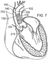
- FIGS. 7-13 illustrate one exemplary procedure for deploying the support stent and securing a THV to the support stent.
- FIGS. 7-8 are cross-sectional views through the left side of a patient's heart showing the acts performed in delivering the support stent 10 through the aortic arch to the aortic valve.
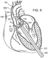
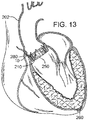
- FIGS. 9-13 are cross-sectional views through the left side of a patient's heart showing the acts performed in deploying a THV 250 and having it engage the support stent 10.
- the guide catheter 102 is shown partially cut away in FIGS. 7-13 .
- certain details concerning the delivery system of the THV 250 are omitted.
- FIG. 7 shows the guide catheter 102 of the delivery system 100 as it is advanced through the aortic arch 202 into a position near the surface of the outflow side of the aortic valve 210.
- the delivery system 100 can be inserted through the femoral artery of the patient and advanced into the aorta in the retrograde direction.
- FIG. 7 also shows the stent delivery catheter 108, the inner catheter 118, and the support stent 10.
- the support stent 10 is in its radially compressed, predeployment state.
- the outer fork 140 and the inner fork 138 which couple the radially compressed support stent 10 to the distal ends of the stent delivery catheter 108 and the inner catheter 118, respectively.
- FIG. 8 shows the support stent 10 after it has been advanced through the distal end of the guide catheter 102 and assumes its final, uncompressed shape in a position above and adjacent to the aortic valve 210.
- the support stent 10 can also be placed directly on the surface of the outflow side of the aortic valve.
- FIG. 8 shows that the stent delivery catheter 108 and the inner catheter 118 have been advanced though the distal end of the guide catheter 102, thereby pushing the support stent 10 out of the guide catheter and allowing it to expand into its natural shape.
- the support stent 10 is rotated and positioned as necessary so that the support stent generally circumscribes the aortic valve and so that the peaks of the support stent are aligned with the tips of the natural leaflets of the aortic valve 210. Therefore, when the THV is inserted and expanded within the aortic valve 210, the leaflets of the aortic valve will engage at least the majority of the surface in the interior of the support stent 10. This alignment will create an overall tighter fit between the support stent 10 and the THV.
- the support stent 10 is rotated and positioned as necessary so that the peaks of the support stent 10 are aligned with the commissures or other portions of the aortic valve.
- the position of the guide catheter 102 and the support stent 10 relative to the aortic valve 210, as well as the position of other elements of the system, can be monitored using radiopaque markers and fluoroscopy, or using other imaging systems such as transesophageal echo, transthoracic echo, intravascular ultrasound imaging (“IVUS”), or an injectable dye that is radiopaque.
- the prongs of the outer fork 140 and the prongs of the inner fork 138 are secured to the support stent 10 until the THV is deployed and frictionally engaged to the support stent.
- the inner and outer forks desirably form a connection between the stent 10 and the delivery system that is secure and rigid enough to allow the clinician to hold the stent 10 at the desired implanted position against the flow of blood while the THV is being implanted.
- the support stent 10 is self-expanding. In other embodiments, however, the support stent may not be self-expanding. In such embodiments, the support stent can be made of a suitable ductile material, such as stainless steel.
- a mechanism for expanding the support stent can be included as part of the delivery system 100.
- the support stent can be disposed around a balloon of a balloon catheter in a compressed state.
- the balloon catheter can have a shaft that is interior to the inner catheter 118. Because the stent 10 is not self-expanding, the distal end portion of the guide catheter 102 need not extend over the compressed support stent.
- the support stent, balloon catheter, inner catheter 118, and stent delivery catheter 108 can be advanced from the distal end of the guide catheter 102.
- the balloon portion of the balloon catheter can be inflated, causing the support stent to expand.
- the balloon portion can subsequently be deflated and the balloon catheter withdrawn into the delivery system 100 to remove the balloon from the interior of the support stent while the support stent remains connected to the inner catheter for positioning of the support stent.
- the delivery of the support stent otherwise proceeds as in the illustrated embodiment using the self-expanding support stent 10.
- FIG. 9 shows an introducer sheath 220 passing into the left ventricle through a puncture 222 and over a guidewire 224 that extends upward through the aortic valve 210.
- the clinician locates a distal tip 221 of the introducer sheath 220 just to the inflow side of the aortic valve 210.
- the position of the introducer sheath 220 relative to the aortic valve 210, as well as the position of other elements of the system, can be monitored using radiopaque markers and fluoroscopy, or using other imaging systems.
- FIG. 10 shows the advancement of the balloon catheter 230 over the guidewire 224 and through the introducer sheath 220.
- the THV 250 is located at the aortic annulus and between the native aortic leaflets.
- FIG. 11 also illustrates retraction of the introducer sheath 220 from its more distal position in FIG. 10 .
- Radiopaque markers may be provided on the distal end of the introducer sheath 220 to more accurately determine its position relative to the valve 210 and balloon 232.
- FIGS. 10-11 do not show the front third of the support stent 10 or the corresponding outer and inner prong of the outer fork and the inner fork, respectively.
- FIGS. 12-13 show the front third of the support stent 10 and the front of the THV 250, but do not show the portions of the native heart valve that would be secured by the front of the support stent 10. It is to be understood, however, that a corresponding leaflet of the native heart valve would be secured between the support stent 10 and the THV 250.
- the precise positioning of the THV 250 may be accomplished by locating radiopaque markers on its distal and proximal ends.
- the clinician can adjust the position of the valve 250 by actuating a steering or deflecting mechanism within the balloon catheter 230.
- the rotational orientation of the valve 250 can be adjusted relative to the cusps and commissures of the native aortic valve by twisting the balloon catheter 230 from its proximal end and observing specific markers on the valve (or balloon catheter) under fluoroscopy.
- One of the coronary ostia 280 opening into one of the sinuses of the ascending aorta is also shown in FIG. 11 , and those of skill in the art will understand that it is important not to occlude the two coronary ostia with the prosthetic valve 250.
- FIG. 11 shows the THV 250 in its contracted or unexpanded state crimped around the balloon 232.
- the balloon 232 is expanded to engage the support stent 10 as seen in FIG. 12 .
- the engagement of the support stent 10 to the exterior of the THV 250 pinches the leaflets of the aortic valve between the support stent and the THV 250, and thereby secures the THV within the annulus of the aortic valve.
- the inner catheter 118 of the delivery system 100 can be retracted, thereby causing the prongs of the inner fork 138 to become disengaged from the retaining arms of the support stent 10.
- the prongs of the inner fork 138 can be disengaged from the retaining arms by retracting the stent delivery catheter 108. Once disengaged from the support stent, the delivery system 100 can be retracted from the aortic arch and removed from the patient.
- valve 250 can take a variety of different forms and may comprise an expandable stent portion that supports a valve structure.
- the stent portion desirably has sufficient radial strength to hold the valve at the treatment site and to securely engage the support stent 10. Additional details regarding balloon expandable valve embodiments that can be used in connection with the disclosed technology are described in U.S. Pat. Nos. 6,730,118 and 6,893,460 , both of which are hereby expressly incorporated herein by reference.
- the balloon 232 is deflated, and the entire delivery system including the balloon catheter 230 is withdrawn over the guidewire 224.
- the guidewire 224 can then be withdrawn, followed by the introducer sheath 220.
- purse-string sutures 260 at the left ventricular apex can be cinched tight and tied to close the puncture.
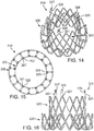
- FIGS. 14-16 shows another embodiment of a support stent or frame 310 that can be used to help secure a THV into the interior of a native heart valve, such as the aortic valve.
- FIG. 14 is a perspective view of the support stent 310
- FIG. 15 is a top view of the support stent 310
- FIG. 16 is a side view of the support stent 310.
- support stent 310 has a generally annular or toroidal body formed from a suitable shape-memory metal or alloy, such as spring steel, cobalt-chromium alloy (Elgiloy®), or nitinol.
- the support stent 310 is also radially compressible to a smaller profile and can self expand when deployed into its functional size and shape. In other embodiments, however, the support stent 310 is not self expanding.
- the support stent 310 includes a generally cylindrical main body portion 320 and a rim portion 330.
- the support stent 310 can be a mesh structure, which can be formed, for example, from multiple elements in which approximately half of the elements are angled in a first direction and approximately half of the elements are angled in a second direction, thereby creating a criss-cross or diamond-shaped pattern.
- the rim portion 330 has a greater diameter than the main body portion 320 and is formed as an extension at a bottom region of the main body portion that is folded outwardly from the main body portion and back toward a top region of the main body portion. The rim portion 330 thus forms a U-shaped rim or lip around the bottom region of the support stent 310.
- the rim portion 330 is designed to have a diameter that is slightly larger than the walls of the aortic arch that surround the aortic valve.
- the rim portion 330 expands to engage the surrounding aorta wall and frictionally secures the support stent 310.
- the main body portion 320 defines an interior into which an expandable THV can be expanded and which further engages the native leaflets of the aortic valve.
- the main body portion 320 operates in the same manner as the support stent 10 described above and illustrated in FIGS. 1-12 , whereas the rim portion 330 of the support stent 310 operates to secure the support stent in place by engaging the walls of the aorta that surround the aortic valve.
- the support stent 310 further includes retaining arms 321, 322, 323 that can be used to help position and deploy the support stent 310 into its proper location relative to the native aortic valve.
- the retaining arms 321, 322, 323 can have respective apertures 326, 327, 328.
- the retaining arms 321, 322, 323 are constructed and function in a similar manner as retaining arms 21, 23, 25 described above in the embodiment illustrated in FIGS. 1-12 .
- FIGS. 17-18 illustrate one exemplary procedure for deploying the support stent 310 and securing a THV 340 within an interior of the support stent.
- FIGS. 17-18 are cross-sectional views through the left side of a patient's heart showing the acts performed in delivering the support stent 310 through the aortic arch to the aortic valve.
- certain details concerning the delivery system of the THV 340 are omitted. Additional details and alternative embodiments of the delivery system for the THV 340 that may be used with the support stent described herein are discussed in U.S. Patent Application Publication No. 2008/0065011 ( U.S. application Ser. No. 11/852,977 ) and U.S. Patent Application Publication No. 2007/0005131 ( U.S. application Ser. No. 11/152,288 ), which are hereby expressly incorporated herein by reference.
- FIG. 17 shows an outer catheter 352 (which can be a guide catheter) of a delivery system 350 as it is advanced through the aortic arch 302 into a position near the surface of the outflow side of the aortic valve 304.
- the delivery system 350 can be inserted through the femoral artery of the patient and advanced into the aorta in the retrograde direction.
- FIG. 17 also shows a stent delivery catheter 354, an inner catheter 356, and the support stent 310. Also seen in FIG. 17 are the outer fork 360 and the inner fork 362, which couple the support stent 310 to the distal ends of the stent delivery catheter 354 and the inner catheter 356, respectively.
- FIG. 17 shows the support stent 310 after it has been advanced through the distal end of the guide catheter 352 and assumes its final, uncompressed shape in a position adjacent to the aortic valve 304.
- FIGS. 17-18 do not show the entire front side of the support stent 310 or the corresponding valve leaflet that would be secured by the front side of the support stent 310. It is to be understood, however, that in practice the entire support stent 310 would exist and engage a corresponding leaflet of the native heart valve.
- the support stent 310 can be positioned adjacent to the aortic valve 304 so that the rim portion 330 of the support stent engages the walls surrounding the aortic valve 304 and exerts an outward force against those walls, thereby securing the support stent 310 within the aorta.
- This positioning can be achieved, for example, by advancing the guide catheter 352 to a position directly adjacent the aortic valve 304 while the stent delivery catheter 354 and the inner catheter 356 are undeployed and while the support stent 310 remains in its compressed state.
- the guide catheter 352 can then be retracted while the stent delivery catheter 354 and the inner catheter 356 are held in place, thereby allowing the support stent 310 to expand toward its natural shape.
- the position of the guide catheter 352 and the support stent 310 relative to the aortic valve 304, as well as the position of other elements of the system can be monitored using radiopaque markers and fluoroscopy, or using other imaging systems such as transesophageal echo, transthoracic echo, IVUS, or an injectable dye that is radiopaque.
- the prongs of the inner fork 362 can be disengaged from the corresponding apertures of the retaining arms of the support stent 310.
- the inner catheter 356 can be retracted into the interior of the stent delivery catheter 354, thereby releasing the support stent 310 from the outer fork 360 and the inner fork 362.
- the delivery system 350 can then be retracted from the aorta and removed from the patient's body.
- a THV (such as any of the THVs discussed above) can be introduced.
- a delivery system having a delivery catheter that is advanced through the patient's aorta can be used to deliver the THV.
- a transfemoral approach can be used.
- any of the exemplary systems and methods described in U.S. Patent Application Publication No. 2008/0065011 ( U.S. application Ser. No. 11/852,977 ) or U.S. Patent Application Publication No. 2007/0005131 ( U.S. application Ser. No. 11/152,288 ) can be used with the support stent 310.
- the transapical approach shown in FIGS. 7-13 can be used.
- FIG. 18 shows delivery system 380 comprising an outer catheter 382 (which can be a guide catheter) and a balloon catheter 390 extending through the guide catheter.
- the balloon catheter 390 has a balloon at its distal end on which the THV is mounted.
- the delivery system 380 can be inserted through the femoral artery of the patient and advanced into the aorta in the retrograde direction.
- FIG. 18 further shows a guidewire 392 that has been first inserted into the patient's vasculature and advanced into the left ventricle. The delivery system can then be inserted into the body and advanced over the guidewire 392 until the THV is positioned within the interior of the aortic valve.
- the THV is not only in the interior of the aortic valve 304 but also in the interior of the main body portion of the support stent 310.
- FIG. 18 shows the THV 340 in its contracted (or unexpanded) state crimped around the balloon portion of the balloon catheter 390.
- the balloon of the balloon catheter 390 can be expanded such that the THV 340 expands and urges the native leaflets of the aortic valve against the support stent 310, thereby securing the THV within the annulus of the aortic valve.
- the balloon of the balloon catheter 390 is deflated, and the entire delivery system 380 including the balloon catheter is withdrawn over the guidewire 392. The guidewire 392 can then be withdrawn.
- a support stent and THV are delivered surgically to the desired heart valve (e.g ., in an open-heart surgical procedure).
- the support stent and THV are delivered surgically, non-compressible support stents and/or THVs are used.
- Aortic insufficiency can cause dilatation of the ascending aorta, causing aneurisms, as well as the aortic annulus.
- embodiments of the present invention provide for anchoring of a deflector that directs blood away from the aneurysm while at the same time treating the insufficient heart valve.
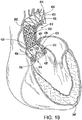
- a medical device 410 for treating AI includes a support structure 412, a stent 414, a prosthetic valve 416 and a deflector 418.
- the support structure 412 is configured, similar or the same as the support structures described hereinabove, to cooperate with the prosthetic valve 416 to pinch the native valve therebetween and provide an anchor for the stent 414 which extends into the aorta and supports the deflector 418 which is positioned to abate blood flow against the aneurysm.
- the support structure 412 (stent or frame) includes, for example in FIG. 19 , peaks 420, 422, 424 and valleys 430, 432, 434 and retaining arms 421, 423, 425 defining apertures 426, 427, 428. Similar to the other embodiments of the support structures disclosed herein, a range of variations are possible for anchoring the both the stent 414 and the prosthetic valve 416 and the deflector 418.
- the shape of the support stent or frame 410 can vary from implementation to implementation.
- the support stent is not sinusoidal or otherwise shaped in the z-plane.
- the support stent is shaped as a cylindrical band or sleeve.
- the support stent or frame can be any shape that defines an interior through which a THV can be inserted, thereby causing the native leaflets of the aortic valve (or other heart valve) to be pinched or securely held between the support stent and the THV.
- the support stent can have a more complex structure.
- the support stent illustrated in FIG. 19 is formed from a single annular member (or strut), the support stent can comprise multiple annular elements that interlock or are otherwise connected to one another ( e . g ., via multiple longitudinal members).
- the prosthetic valve 416 of the embodiment illustrated in FIG. 19 is a THV that is similar to the one illustrated in FIG. 1 .
- THV THV
- this particular usage is for illustrative purposes only and should not be construed as limiting.
- embodiments of the disclosed support structure can be used to secure a wide variety of THVs delivered through a variety of mechanisms (e . g ., self-expanding heart valves, other balloon-expanding heart valves, and the like).
- any of the embodiments described in U.S. Pat. No. 6,730,118 can be used with embodiments of the disclosed support structure.
- the stent 414 is a scaffold that is coupled to the support structure 412 and extends from the support structure into the aorta (and over the insufficient portions of the aorta).
- the stent 414 has a proximal end 430, a distal end 432, and a plurality of interconnected struts 434 defining a plurality of cells 436.
- the proximal (with respect to the heart) end 430 of the stent 414 is connected or coupled to the support structure 412 by being formed therewith or attachment by wires or other supports.
- the support structure 412 and stent 414, including the plurality of interconnected struts 434 may be laser cut from a single metal tube.
- coupling may also be by assembly after separate formation, include assembly in vivo as each portion of the medical device 410 is delivered.
- the body of the stent 414 that is formed by the interconnected struts 434 that define between them the cells 436.
- the interconnected struts 434 are formed to promote flexibility and facilitate delivery through tortuous paths and extension over the aortic arch.
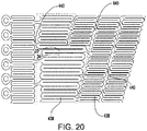
- the strut pattern may be as shown (as a flattened portion of a laser-cut blank prior to expansion) in FIG. 20 and include a plurality of rings 438 formed by sinusoidal struts connected end-to-end, wherein the rings are connected by a plurality of angled, flexible connectors 440.
- the rings 438 may be formed to have variable lengths and the connectors 440 selectively located to promote directional preferences in flexibility and/or variations in cell sizes between them.
- LIFESTENT manufactured by C.R. BARD, INC. which has a multi-dimensional helical structure that facilitates its use in tortuous paths of peripheral vasculature. Aspects of the LIFESTENT are described in U.S. Pat. No. 6,878,162 entitled “Helical Stent Having Improved Flexibility and Expandability" by Bales et al.
- the stent 414 when extending along the aortic arch, has a tightly curved configuration with an external, long curvature 442 and an internal curvature 444.
- the cell sizes may be larger to allow for the longer path length.
- These cell sizes may be programmed into the stent by selective cutting and formation of the struts and cells and/or may appear due to the mechanical application of insertion and delivery into the aortic arch.
- the internal curvature 444 may be programmed through selection of the strut structure and/or due to delivery.
- the stent 414 may include structure that facilitates engagement, frictional or mechanical, of the surrounding lumen (e.g ., the aorta) where the lumen is in adjacent contact with the stent.
- the struts 434 and cells 436 may have a pattern that facilitates frictional engagement, or may have barbs or hooks or microanchors or flared portions formed thereon to mechanically engage the lumen and facilitate the support structure 412's role of securing the medical device 410.
- the distal end 432 of the stent 414 is positioned within the aortic arch distal the branch (e . g ., brachiocephalic, common carotid and left subclavian) arteries extending off of the aorta.
- the distal end 432 may be a termination of the last row of the rings 438 or may include its own retaining arms 446 defining apertures 448. Use of the retaining arms 446 and apertures 448 enables use of the delivery apparatus 110 shown in FIGS. 3 and 4 and described hereinabove.
- the distal end 432 may also include structure configured to engage the surrounding lumen walls for additional security of the medical device 410. For example, it may include hooks or barbs or micro anchors.
- the cells 436 may include a relatively large cell structure positioned over and near the branch arteries. This facilitates perfusion of the branch arteries, such as by being located over the branch arteries at the aortic arch or closer to the valve for communication with the coronary arteries.
- the cell structure is relatively large in comparison to the remaining cells configured to support the lumen walls or abate blood flow against aneurysms or further vascular dilatation.
- the cell size may be selected to guard the branch arteries against embolic debris, so as to act as a partial deflector of such debris.
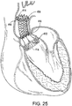
- the length of the device 410 may be enough to extend from the native leaflets, through the sinus of valsalva, into the ascending aorta, over the aortic arch and potentially into the descending aorta.
- the length of the device 410 may be 30 mm to 100 mm or longer.
- the stent 414 may also be tapered, small at the annulus to larger at the ascending aorta, columnar or have ends that are a larger diameter for sealing and anchoring, as shown in FIG. 21 .
- this support structure 412 and stent 414 act like a scaffold or anchoring device for other devices to be deployed inside of it, such as the prosthetic valve 416, which is delivered and anchored as described above, and one or more deflectors 418.
- the deflector 418 is a covered stent or graft that is relatively impermeable ( e . g . to blood flow and is configured for positioning over an aneurysm in the aortic arch so as to direct blood flow away from the aneurysm.
- the deflector 418 of the embodiment of FIG. 19 includes a deflector stent 450 supporting a tubular graft material 452 extending around the deflector stent.
- the deflector 450 is mounted within the stent 414 as would a graft being fit within a vessel without the stent 414.
- the deflector 450 may be delivered by a catheter extending retrograde to blood flow within the aorta, or extending from the heart chamber and through the aortic valve, and then expanded (or allowed to expand) once the desired location is reached.
- the stent 414 guards the aneurysm against the expansion pressure of the deflector 418 and the deflector can have a much smaller expanded diameter than the aneurysm and still is assured of a firm anchor.
- Deployment of the medical device 410 of FIG. 19 may include first deploying the support structure 412 and the stent 414 (if they're integrally attached to each other). Then, through the support structure 412 and the sent 414 the THV prosthetic valve 416 is delivered, anchoring it into the proximal end of the device (either the support structure 412 or the stent 414). The covered stent or graft deflector 418 is deployed in the stent 414, covering the area that has the aneurysm and avoiding the branch arteries and associated larger cells 436 of the stent 414. The deflector 418 would then redirect the pulsating blood away from the aneurysm so as to prevent dissection, and the new valve prosthesis 416 would ensure that correct blood flow is restored.
- the deflector 418 is shown in FIG. 19 as being a single graft or covered stent, the term “deflector” should be construed broadly herein to include any structure that serves to abate (reduce) blood flow against the selected portion of the vessel wall.
- deflectors 418 in the form of grafts or covered stents could be delivered and positioned to address anatomical variations in size and positioning of the aneurysm(s).
- the deflector 418 need not be a tubular structure but could be a sheet or shield of material anchored to one side of the stent 414.
- the deflector 418 need not be separately attached, but could be a portion of the stent 414 with reduced permeability, such as through a polymeric coating.
- FIG. 21 shows another example wherein the stent 414 is covered with a deflector 418 at the time of delivery.
- FIG. 22 shows another example wherein the stent 414 is covered with a deflector 418 in the form of a balloon 454.
- the balloon not only deflects blood flow, but also can be inflated so as to expand into and fill the space between the stent 414 and the aneurysm wall.
- Inflation may be by fluid, such as saline wherein the balloon may include a one-way check valve that stops outflow of the saline after detachment of the inflation lumen.
- inflation may be by a polymer or other fluid that sets or cures or thickens and can therefore maintain the fill shape after intervention is complete.
- the expansion forces of the balloon 454 are sufficiently low so as to not further expanded the aneurysm but at the same time cause the balloon to take the shape of the aneurysm space.
- the balloon therefore, may be comprised of a very pliable material such as a silicone that expands under low pressure and/or may even include a woven material.
- a very pliable material such as a silicone that expands under low pressure
- the woven material may have a limit to expansion and will protect the aneurysm from dissection if the woven balloon is fashioned to fit the aneurysm.
- FIG. 23 shows another example wherein the stent 414 is covered with a deflector 418 in the form of a foam sleeve 456.
- the foam may be an open celled foam or a closed-cell foam that promotes friction with the surrounding lumen at initial implantation. If open celled the blood will in-grow and create a barrier for the blood not to pass along the aortic wall.
- the foam may be configured for up to 300% compression.
- the foam may be configured, such as by being hydrophilic, to absorb and expand in blood and fill the space between the stent 414 and the lumen.
- a skin or impermeable layer can be also applied to the stent 414 or foam sleeve 456 so that the foam does not peel/break off and cause an embolism.
- the skin or impermeable layer inhibits seep of the passing blood through the foam to the aortic wall.
- an inner surface of the foam sleeve 456 may have a relatively impermeable skin (such as a closed cell foam) to promote passage of blood therethrough while the outer surface is open celled and permeable for expansion.
- the foam may also have coagulation properties that promote buildup of clots to help secure the medical device 410 and fill the aneurismal space.
- the foam may include, for example, a flexible ester polyurethane, reticulated open cell, felted foam with a pore size of 80-100 ppi, a density of 5.4-6.3 pcf.
- thick woven sleeves may be used that expand in response to absorbing blood, such as a hydrophilic weave or foam.
- the foam sleeve 456 is crimped down with the stent 414 and then placed in the aorta of the patient.
- the stent 414 expands and maintains its more rigid shape, whereas the foam can also expand and take up the current shape of the aorta.
- the foam advantageously fills the void between the stent 414 and the aneurysm wall, preventing blood (the continued pulse force) from reaching the aneurysm.
- the foam sleeve 456 creates a seal within the aorta forcing blood to be passed through the stent 414 diameter. It also has effective friction or outward forces on the aortic wall so as to restrict movement.
- FIG. 24 shows another example wherein the deflector 418 has an annulus or donut shape, such as a foam or balloon annulus. With its reduced length, the donut may be positioned at the location of the aneurysm, thereby blocking the flow of blood to this particular section of the aortic wall.
- an annulus or donut shape such as a foam or balloon annulus.
- FIG. 25 shows another example including two donut or annulus shaped deflectors 418 on the stent 414 which aid in retention of the device within the aorta.
- donuts may be placed on opposite sides of the aneurysm and seal the aneurysm against blood flow.
- the donuts may be foam, balloons or other expansion members.
- the deflector 418 may include micro anchors attached to the foam or balloon section to aid in retention if the expansion force of the foam or balloon is not suitable in larger aortas.
- the deflector 418 may include mechanical clot facilitators such as wires, coils or springs that fill the space between the stent 414 and the aneurysm walls to promote embolization therebetween.
- mechanical clot facilitators such as wires, coils or springs that fill the space between the stent 414 and the aneurysm walls to promote embolization therebetween.
- FIG. 26 shows another embodiment of the present invention wherein the deflector 418 (in the form of a graft) may include a seal 458 in the form of a slit configured to allow passage into the interior of the stent 414.
- the seal 458 may include overlapping portions or lips of the graft material that self-seal by closing up after removal of delivery tool.
- the seal may be a valve, such as a duckbill valve.
- the graft 418 with the seal 458 may be used in a during a "trans-aortic" THV implantation wherein the graft is first deployed in a percutaneous delivery.
- the THV is then delivered through the chest wall with a delivery tool (e.g ., a catheter) and through a slit in the aorta (aortotomy) and finally through the slit or seal 458 in the graft.
- the slit then seals around the delivery tool to prevent blood loss.
- the THV is expanded into place within the support structure 412 or stent 414.
- the seal 458 closes when the delivery tool is removed, allowing the aorta to be sutured without blood escaping.
- the graft 418 could be left behind - or it could be retrieved after completion of the procedure.
- Such a seal 458 may be employed in a range of embodiments with the deflector 418, including the embodiments disclosed herein.
- FIG. 27 shows another embodiment wherein the deflector 418 has an hourglass shape and is constructed of a resilient material that deflects in response to increased blood pressure of a heart beat and adds additional pumping action as the arterial pressure drops.
- the hourglass shape is formed of resilient walls that deflect under pressure and spring back into shape as the pressure drops.
- the walls of the graft may be relatively thick for an increased resiliency and additional pumping action.
- two anchoring stents may be connected by an elastic tube (e.g ., made out of silicone).
- One of the anchors is deployed in the STJ (right above the native valve) and the other anchor is deployed on the other end of the aneurysm somewhere in the ascending aorta prior to the branches.
- the elasticity of the tube would aid the heart's pumping action.
- each of the medical devices 410 described herein is capable of a large amount of compression.
- the device 410 including the embodiment of the stent 414 and its foam sleeve 456, can be compressed or crimped to a diameter that is 8 mm or less. Uncompressed, the diameter may be 50 mm to 90 mm.
- a method of using the medical device 410 disclosed herein includes delivering the support structure 412 to a position on or adjacent to the surface of the outflow side of the native heart valve of the patient, wherein the support structure defines a support-structure interior.
- the expandable prosthetic heart valve 416 is delivered into the native heart valve and into the support-structure interior.
- the expandable prosthetic heart valve 416 is expanded while it is in the support-structure interior and while the support structure is at the position on or adjacent to the surface of the outflow side of the native heart valve. This causes one or more of the native heart valve leaflets to be frictionally secured between the support structure 412 and the expanded prosthetic heart valve 416.
- the stent 414 which is coupled to the support structure 412 either by co-formation or later attachment, is extended into a vessel (such as the aorta) extending from the native heart valve.
- the deflector 418 is already present on the stent 414 and/or is delivered into and attached to the stent 414. Blood flow against the vessel is abated by the deflector 418.
- the method also may include delivering the stent 414 (or portions thereof) to a position adjacent the support structure 412 and coupling it to the support structure prior to extending the stent into the vessel.
- the deflector 418 may be delivered to a support position on the stent 414 and coupled to the stent in vivo.
- the portions could be individually delivered and coupled to each other in vivo.
- the method includes avoiding arteries extending from the vessel when positioning the deflector.
- the method may include expanding the deflector 418 to fill at least a portion of the space between an external surface of the stent 414 and the vessel.
- FIG. 29 shows another embodiment of a support stent or frame 500 that can be used to treat valve insufficiency (e . g ., aortic insufficiency, mitral insufficiency, etc.), or to help secure a THV within the interior of a native heart valve.
- the support stent 500 comprises an annular main body 501 formed by a plurality of angled struts 502 arranged in a zig-zag pattern and having one or more apices 504 formed by the intersection of two adjacent struts.
- the struts 502 can be configured such that there is a gap 506 between adjacent struts underneath the apices 506 that receives portions of two adjacent leaflets forming a commissure of a native valve, as shown in FIG. 30 .
- the support stent has a gap 506 for each commissure of the native valve where the support stent is to be implanted.
- the support stent 500 desirably has three, angularly spaced gaps 506, with each gap being positioned at a commissure of the native valve when the support stent 500 is implanted.
- the gaps 506 can be dimensioned to pinch or clamp adjacent leaflets to each other at respective commissures.
- the support stent desirably has two gaps 504. In this manner, the support stent 500 can retain or clamp the native valve leaflets together, thereby reducing the effective orifice area of the valve which, in turn, can reduce regurgitation through the valve.
- a THV can be deployed within the native valve, using a stent 500 as dock as shown in FIGS. 10-13 .
- the stent 500 and the THV can be implanted in the same procedure, using the stent 500 as the dock for the THV.
- stent 500 simplifies the procedure since the stent 500 can "clip" onto the commissures of the native leaflets and retain its position once deployed, which obviates the need to hold the stent in place using one catheter while the THV implanted using another catheter as is shown in FIG. 12 .
- the support stent 500 can also be used to treat native valve insufficiency by reducing the diameter of the valve annulus.
- the support stent 500 can be anchored in the valve annulus by one or more microanchors 508 comprising one or more sets of barbs 510.
- Exemplary embodiments of microanchors that can be used with the disclosed technology can be found in U.S. Patent Application No. 13/910,975 ( U.S. Publication No. 2013/0331930 ), which is incorporated herein by reference.
- the microanchors 508 can be positioned in the gaps 506 adjacent the apices 504 of the support stent and can be embedded in the tissue of the valve annulus.
- One or more sutures 512 coupled to the microanchors 508 can extend upwardly toward a delivery system (not shown) and can comprise one or more suture securement devices, such as a suture clip 514.
- the suture clip 514 can be configured to travel along the sutures 512 in the direction indicated by arrow 516 (i.e., toward the microanchors 508).
- tension is applied to the sutures 512 (by pulling upwardly on sutures and/or pushing downwardly on the suture clip) the suture clip can resist travel of the sutures 512 through the suture clip 514 in the opposite direction (i.e., the suture clip can resist downward travel of the sutures relative to the clip).
- Exemplary embodiments of suture securement devices that can be used with this technology can be found in U.S. Patent Application No. 13/938,071 ( U.S. Publication No. 2014/0031864 ), which is incorporated herein by reference.
- the suture clip 514 retains tension on the sutures 512, thereby retaining the support stent and the surrounding tissue in the reduced diameter state after implantation. In this manner, the support stent 500 can be used to reduce the diameter of the valve annulus.
- the support stent 500 can be implanted in a procedure in which the microanchors 508 are deployed adjacent the commissures of the native valve with each microanchor 508 being provided with a suture 512 that can extend to a delivery apparatus and/or outside the body.
- three microanchors 508 (each having a respective suture) can be implanted.
- the sutures 512 can be threaded through openings in the apices 504 of the support stent 500, which can then be advanced along the sutures until it is placed against the aortic surface of the native leaflets.
- a suture clip 514 can be advanced down the sutures 512 to tension the sutures and draw the surrounding tissue inwardly to reduce the diameter of the native annulus (as depicted in FIGS. 31-32 ).
- the support stent 500 can be made of a self-expanding material (e.g., Nitinol) and is delivered and deployed using an expansion mechanism (e.g., a balloon catheter).
- an expansion mechanism e.g., a balloon catheter.
- the expansion mechanism over expands the support stent (i.e., expands the support stent radially beyond its functional size) (such as by inflating the balloon of the balloon catheter) and places the support stent against the aortic surface of the native valve.
- the support stent 500 can have barbs or anchors 508 can that engage, penetrate and/or grab adjacent tissue as the support stent 500 is placed against the native tissue.
- the support stent 500 can be configured to clip onto commissures of the native valve when the commissures are placed in gaps 506.
- the expansion mechanism then releases the support stent 500 (such as by deflating the balloon), allowing the support stent to shrink/return to its natural or functional size, pulling the surrounding tissue inwardly to reduce the size of the native annulus.
- the aortic annulus can be reduced in size by suturing the support stent 500 in its functional size to the aortic valve.
- FIG. 33 shows another embodiment of a support stent or frame 600 that can be used to treat heart valve insufficiency or help secure a THV within the interior of a native heart valve, such as the aortic valve.
- the support stent 600 comprises an annular main body 601 formed by a plurality of angled struts 602 arranged in zig-zag pattern.
- the support frame 600 can include one or more leaflet-engaging mechanisms 603.
- the leaflet-engaging mechanisms 603 can comprise pairs of leaflet-engaging members 604 secured to respective struts 602 below one or more apices 606 formed by the intersection of the two adjacent struts 602.
- Each leaflet-engaging member 604 has a fixed end portion 608 secured to a respective strut and a free end portion 610.
- the leaflet-engaging members 604 extend upwardly toward the apex 606 and toward each other. In their normal, unbiased (i.e., non-deflected) state, the leaflet-engaging members 604 can be configured such that there is a small gap between respective free end portions 610 that receives portions of two adjacent leaflets 616 forming a commissure of a native valve, as further described below.
- the struts 602 and the leaflet-engaging members 604 can be laser cut (or otherwise machined or formed) from a single piece of material ( e . g ., a tubular piece of metal) such that the leaflet-engaging members 604 are integral to the support stent. In other embodiments, the leaf springs 604 can be separately formed and welded to the struts 602.
- the support stent has a pair of leaflet-engaging members 604 for each commissure of the native valve where the support stent is to be implanted.
- the support stent 600 desirably has three, angularly spaced pairs of leaflet-engaging members 604, with each pair being positioned underneath an apex 606 that is positioned at a commissure of the native valve when the support stent 600 is implanted.
- the support stent desirably has two pairs of leaflet-engaging members 604.
- the number of pairs of leaf springs can be less than the number of commissures of the native valve where the support stent is to be implanted.
- the support stent 600 can have retaining arms 612 for releasably securing the support stent 600 to a delivery apparatus (e.g., delivery apparatus 350).
- FIG. 34 shows the support stent 600 implanted in the aortic root behind the leaflets 616 of an aortic valve 614.
- the support stent 600 can be mounted in a compressed state on a delivery apparatus 350 ( FIG. 17 ) and delivered to the vicinity of the native aortic valve, as described in detail above.
- the support stent 600 can be deployed from the catheter 352, allowing the support stent to expand to its functional size.
- Each pair of leaflet-engaging members 604 is rotationally aligned within one of the commissures of the aortic valve.
- each pair of leaflet-engaging members 604 is further advanced toward the aortic valve, causing each pair of leaflet-engaging members 604 to slide over a pair of native leaflets 616 of one the commissures of the aortic valve.
- the gap between the free end portions 610 of the leaf springs is such that insertion of the native leaflets 616 can place the leaf springs in tension and pinch the native leaflets between the leaf springs.
- a THV can be implanted within the interior of the aortic valve 614 (as shown in FIG. 18 ) and expanded against the native leaflets 614, which in turn are pressed radially outwardly against the support stent.
- FIG. 35 shows a modification of the support stent 600 having leaflet-engaging members 604 with spherical free end portions 618 that are configured to contact each other in their normal, unbiased (non-deflected) state.
- the curved outer surfaces of the spherical free end portions 610 can help to engage the native leaflets placed between the spherical free end portions 618 without damaging the leaflets.
- the leaflet-engaging members 604 can flex such that the spherical free end portions 618 move upwardly and away from each other to allow the leaflets to slide between the spherical free end portions 618 (as depicted in FIG. 35 ).
- FIG. 36 shows another modification of the support stent 600 having leaflet-engaging members 604 with curved free end portions 620, which can enhance the retention force against the leaflets while minimizing bulkiness of the leaflet-engaging members 604.
- FIG. 37 shows the support stent of FIG. 36 implanted within the aortic root with a pair of leaflets 616 captured between the free end portions 620 of the leaflet-engaging members 604.
- FIG. 38 shows another modification of the support stent 600 having a single leaflet-engaging member 604 below one or more selected apices 606.
- the leaflet-engaging member 604 is configured to capture a pair of leaflets 616 between a spherical free end portion 618 of the leaflet-engaging member 604 a protrusion 622 extending toward the leaflet-engaging member 604.
- the protrusion 622 is shaped to snag or bind against the adjacent leaflet 616 to help retain the leaflets 616 in place between the leaflet-engaging member 604 and the protrusion.
- the leaflets 616 can be captured between the spherical free end portion 618 of the leaflet-engaging member 604 and the surface of an adjacent strut 602.
- FIG. 39 illustrates another modification of the support frame 600, wherein the leaflet-engaging members 604 are configured to extend from distal apices 624 formed by the intersection of two adjacent struts 602 at the outflow end of the support frame 600.
- FIG. 40 shows another embodiment of support stent 700 comprising an annular main body 701 (shown flattened) formed by a plurality of struts 702. Positioned beneath one or more selected apices 704 of the support stent are leaflet-engaging mechanisms 705 comprising pairs of leaflet-engaging members 706 configured to capture a respective pair of native leaflets.
- each leaflet-engaging member 706 has a first end 708 secured to a strut 702 and a second end 710 secured to the same strut 702.
- Each leaflet-engaging member 706 can have a plurality of curved sections 712 extending between the first and second ends 708, 710, respectively, allowing adjacent leaflet-engaging members 706 of a pair to deflect away from each other while a pair of native leaflets are inserted therebetween.
- Each pair of leaflet-engaging members 706 can also apply sufficient compressive force against the leaflets once they are in place between the leaflet-engaging members 706 such that the leaflets are retained between the leaflet-engaging members 706.
- the leaflet-engaging members 706 can be configured to define a small gap between the curved sections 712 of adjacent members 706.
- the curved sections 712 can define points of contact that can contact corresponding contact points of an adjacent member 706 when the members 706 are in their non-deflected state.
- FIG. 41 illustrates another embodiment of a support frame 800 shown in a flattened or unrolled state for purposes of illustration.
- the support frame 800 comprises an annular main body 801 formed by a plurality of struts 802, and one or more leaflet-engaging mechanisms 803.
- the leaflet-engaging mechanisms 803 can comprise pairs of semi-annular leaflet-engaging members 804 positioned beneath respective apices 806 of the support frame.
- Each leaflet-engaging member 804 in the illustrated embodiment comprises first and second fixed end portions 808, 810 secured to a respective strut 802 and a peak 812 formed by a portion of the leaflet-engaging member 804 intermediate the two fixed end portions 808, 810.
- the leaflet-engaging members 804 can extend generally in the direction of the outflow end of the support frame 800 such that the first fixed end portion 808 is closer to the apex 806 than is the peak 812.
- FIG. 42 shows the support frame 800 implanted in the aortic root 814 with the native leaflets 816 of the aortic valve 818 captured between respective pairs of leaflet-engaging members 804.
- FIG. 43 shows another embodiment of a support stent 900 comprising a plurality of struts 902 and a plurality of leaflet-engaging mechanisms 903.
- the leaflet-engaging mechanisms 903 can comprise clipping members 904 secured to distal apices 916 of the struts 902 at the inflow end of the support stent 900.
- FIG. 44 shows a clipping member 904 apart from the support stent 900.
- Each clipping member 904 comprises two leg portions 906 secured to each other at an apex 908.
- Each leg portion 906 has a free end portion 910 that can be angled inwardly toward the other free end portion 910 as shown.
- Each clipping member 904 can be secured to the support frame 900 with a section of fabric cloth 912 that extends around the apex 908 of the clipping member 904 and an adjacent distal apex 916 of the support frame 900 at the inflow end of the support frame. Sutures can be used to secure the cloth 912 in place around the clipping member 904 and the adjacent distal apex 916 of the support frame 900. As can be seen in FIGS. 43 and 45 , two leg portions 906 of adjacent clipping members 904 can extend toward each other for capturing a pair of native leaflets 914.
- the clipping members 904 can be separately formed from the support frame 900, and can be fabricated from metal wire having a diameter that is smaller than the diameter of the struts 902.
- the diameter of the clipping members 904 can be from about 0.010 inch to about 0.023 inch.
- Each leg portion 906 of the clipping members 904 can also have a length L of, for example, 5 mm or greater ( FIG. 46 ). In this manner, the clipping members 904 can be configured to apply an inward retaining force Fin on the aortic valve leaflets, as shown in FIGS. 45 and 46 .
- the retaining force F in can be about 3 N.
- the clipping members 904 can also have a removal force F R needed to remove or reposition the device 900 along the leaflets 914, and a buckling force F B oriented axially with respect to struts 902.
- the removal force F R and the buckling force F B can be configured such that the application of the required removal force F R can result in a buckling force F B sufficient to cause the clipping members 904 to bend or buckle, thus reducing the risk of tearing the native valve leaflets 914 when repositioning or removing the support frame 900.
- the removal force F R can be about 6 N.
- the clipping members 904 can be integrally formed with the support frame 900.
- FIG. 47 shows another embodiment of support stent 1000 comprising an annular main body formed by a plurality of struts 1002. Positioned beneath one or more selected apices 1004 of the support stent 1000 are leaflet-engaging mechanisms 1003 comprising horseshoe-shaped leaflet-engaging members 1006 configured as clips corresponding to each of the three commissure locations of the native aortic valve. Each of the leaflet-engaging members 1006 can be configured to capture a respective pair of native leaflets at each commissure of the aorta.
- the leaflet-engaging members 1006 and support frame 1000 can be integrally manufactured or separately manufactured and subsequently assembled using any suitable method or combination of, for example, welding, tying with suture or wire, adhesive, mechanically fastening, and the like.
- the phrases "integrally manufactured,” “integrally formed,” and “integral to” all refer to a construction that does not include any adhesive, fasteners, or other means for securing separately formed pieces of material to each other.
- FIGS. 48 and 49 illustrates fragmentary views of another embodiment of a support frame 1100 comprising an annular main body formed by a plurality of struts 1102.
- the support frame 1100 can comprise one or more leaflet-engaging mechanisms 1103 including a pair of integrated leaflet-engagement members 1104.
- the leaflet-engaging members 1104 can be positioned beneath selected apices 1106 and can be configured to capture respective pairs of native leaflets.
- each leaflet-engaging member 1104 has a first end 1108 secured to a strut 1102 and a second end 1110 secured to the same strut 1102.
- Each leaflet-engaging member 1104 can be spring-biased, allowing adjacent leaflet-engaging members 1104 of a pair to deflect away from each other when a pair of native leaflets are inserted between the leaflet-engaging members 1104.
- the leaflet-engaging members 1104 can be configured to apply force against the leaflets such that the leaflets are retained between the leaflet-engaging members 1104.
- the curved leaflet-engaging members 1104 can define points of contact that contact corresponding contact points of an adjacent member 1104 when the members 1104 are in their non-deflected state.
- the members 1104 can be configured to define a small gap between the curved sections of adjacent members 1104, as shown in FIG. 49 .
- the members 1104 can also have diameters greater than, equal to ( FIG. 49 ), or less than ( FIG. 48 ) the diameter of the struts 1102 depending on, for example, the degree of spring-bias desired.
- FIGS. 50 and 51 illustrate a fragmentary view of another embodiment of a support stent 1200 comprising an annular main body formed by a plurality of struts 1202. Beneath one or more selected apices 1204, the struts 1202 can be curved or otherwise shaped such that adjacent struts define a leaflet-engaging mechanism 1203 having a narrow leaflet-engagement region 1206 between the struts 1202.
- the leaflet-engagement region 1206 can comprise a gap dimensioned to grip the native aortic valve leaflets.
- the struts 1202 can be spring-biased, allowing adjacent pairs of struts 1202 to deflect away from each other when a pair of native leaflets are inserted between the struts 1202, and causing the struts 1202 to apply force against the leaflets sufficient to retain the leaflets in place between the struts 1202.
- the leaflet-engagement region 1206 can include teeth or serrations 1208 configured to engage the native leaflets, thereby helping to keep the frame 1200 in place after implantation.
- FIG. 52 shows another embodiment of a stent 1300 comprising an annular main body formed by a plurality of struts 1302.
- the support frame 1300 can include leaflet-engaging mechanisms 1303 located beneath select apices 1304 and defined by the struts 1302.
- the struts 1302 can be separated by narrow leaflet-engagement regions 1306.
- the leaflet-engagement regions 1306 can comprise serrations 1308 configured to engage native leaflets when they are inserted between the struts 1302. In this manner, the stent 1300 can be held in place after implantation.
- FIGS. 53-55 there is shown another embodiment of a support frame 1400 comprising an annular main body 1401 (shown flattened in FIG. 53 ) formed by a plurality of struts 1402.
- the support frame 1400 can comprise one or more leaflet-engaging mechanisms 1403, which can include a pair of leaflet-engaging members 1404 secured to respective struts 1402 below one or more apices 1406 formed by the intersection of two adjacent struts 1402.
- Each leaflet-engaging member 1404 can have a fixed end portion 1408 secured to a respective strut 1402 and a free end portion 1410.
- the leaflet-engaging members 1404 can extend downwardly from near the apices 1406 at the outflow end of the support frame 1400 and toward each other, defining a narrow leaflet-engaging region 1405, before curving toward the struts 1402 near the inflow end of the frame 1400.
- the leaflet-engaging members 1404 in their normal, unbiased (non-deflected) state, can be configured such that there is a small gap between free end portions 1410 and the struts 1402. In this manner the leaflet-engaging members 1404 can deflect toward adjacent struts 1402 when the leaflets 1414 of a native valve are inserted therebetween, as shown in FIG. 55 .
- the struts 1402 and the leaflet-engaging members 1404 can be laser cut (or otherwise machined or formed) from a single piece of material (e.g., a tubular piece of metal) such that the leaflet-engaging members 1404 are integral to the support stent.
- the leaflet-engaging members 1404 can be separately formed and welded to the struts 1402.
- the support frame 1400 can comprise a pair of leaflet-engaging members 1404 located beneath each apex 1406 of the frame. This can make implantation of the support frame 1400 easier by reducing the amount by which the frame 1400 must be rotated in order to line up the pairs of leaflet-engaging members with the commissures of the native valve.
- the support frame 1400 can have a pair of leaflet-engaging members 1404 for each commissure of the native valve where the support frame is to be implanted.
- the support frame 1400 when the support frame 1400 is intended to be implanted at the aortic valve or the pulmonary valve, the support frame 1400 desirably has three, angularly spaced pairs of leaflet-engaging members 1404, with each pair being positioned underneath an apex 1406 that is positioned at a commissure of the native valve when the support frame 1400 is implanted.
- the support frame 1400 desirably can have two pairs of leaflet-engaging members 1404.
- the number of pairs of leaflet-engaging members 1404 can be less than the number of commissures of the native valve where the support stent is to be implanted.
- the support stent 1400 can also have retaining arms 1412 ( FIG. 53 ) for releasably securing the support stent 1400 to a delivery apparatus (e.g., delivery apparatus 350).
- FIG. 56 shows a modification of the support stent 1400 having leaflet-engaging members 1404 that overlap one another in their normal (non-deflected) state.
- the leaflet-engaging members 1404 can be configured to retain the native valve leaflets 1414 by applying a preload to the leaflets 1414 once they are captured between the leaflet-engaging members 1404.
- the overlapping region of the leaflet-engaging members 1404 is offset from a central axis 1416 extending though apex 1406, and the respective fixed end portions 1408 of the leaf springs are vertically offset from one another.
- the respective leaflet-engaging members 1404 can overlap symmetrically about the central axis 1416 of the stent, and the fixed end portions 1408 can be fixed to the respective struts 1402 at the same vertical position.
- the free end portions 1410 of the leaflet-engaging members 1404 contact the struts 1402 when the leaflet-engaging members 1404 are in their non-deflected state.
- the free end portions 1410 can be spaced from the struts 1402 such that there is a gap between the free end portions 1410 and the struts 1402, depending upon the degree of spring bias desired in the leaflet-engaging members 1404.
- FIGS. 57 and 58 show another modification of the support frame 1400 having leaflet-engaging members 1404 that comprise or serrations 1418 located in the leaflet engagement region 1405.
- the serrations 1418 can be defined by circular cutouts 1420 such that the serrations 1418 extend outwardly from the leaflet-engaging members 1404 in a direction generally orthogonal to the surface of the leaflet-engaging members 1404, as shown in FIG. 57 .
- the serrations 1418 can aid in retaining the native leaflets between the leaflet-engaging members 1404 after insertion.
- the leaflet-engaging members 1404 can comprise angled cutouts 1422 such that the serrations 1418 are oriented generally in the direction of the outflow end of the support frame 1400, as shown in FIG. 58 .
- the serrations 1418 can allow smooth insertion of the native leaflets between the leaflet-engaging members 1404 (i.e., the orientation of the serrations 1418 can minimize damage to the leaflets caused by the serrations 1418 during insertion) while retaining the native leaflets after insertion between the leaflet-engaging members 1404.
- the leaflet-engaging members 1404 can comprise surface roughness in the leaflet-engagement region 1405 to increase retention of the native valve leaflets.
- FIGS. 59A and 59B show another modification of the support stent 1400 wherein respective leaflet-engaging members 1404 of each pair comprise protrusions 1424 and corresponding cutouts or recesses 1426 configured to receive the protrusions 1424.
- the leaflet-engaging members 1404 can be spring-biased to move between an open position ( FIG. 59A ), wherein the respective leaf springs define a gap therebetween, and a closed position ( FIG. 59B ), wherein the recesses 1426 receive the protrusions 1424 of the corresponding leaflet-engaging member 1404.
- native valve leaflets inserted between the leaflet-engaging members 1404 when the leaflet-engaging members 1404 are in the open position can be engaged and retained between the protrusions 1424 and the recesses 1426 of the respective leaflet-engaging members 1404 when the leaflet-engaging members 1404 are in the closed position.
- FIG. 60 shows a detail view of another embodiment of a stent 1500 comprising an annular main body formed by a plurality of struts 1502.
- Beneath apices 1504 the support frame 1500 can comprise a leaflet-engaging mechanism 1503 in the form of a leaflet-engaging portion 1505 defined by the struts 1502.
- the leaflet-engaging portion 1505 can define a gap 1506 configured to engage and retain native valve leaflets 1508 after insertion of the leaflets into the gap 1506.
- the leaflet-engagement portion 1505 can include a cloth or fabric covering 1510 surrounding the respective struts 1502 and extending over the apex 1504.
- the fabric covering 1510 can be configured to engage the native leaflets 1508 when the leaflets are inserted into the gap 1506.
- the fabric covering 1510 can be configured to reduce wear and/or damage to the native leaflets, as well as to accommodate different leaflet thicknesses.
- Cloth or fabric is optionally included in any embodiment of the support frames disclosed herein at any location where tissue damage or wear is likely to occur.
- FIG. 61 shows a modification of the stent 1500 having a leaflet-engagement portion 1505 that defines a first gap 1506 and a second gap 1514, with the first gap 1506 being narrower than the second gap 1514.
- the first gap 1506 can be defined by an increase in thickness of the respective struts 1502 in the region of the first gap 1506, and can comprise serrations 1516 on the respective struts 1502.
- the first gap 1506, together with the serrations 1516, can aid in retaining the native leaflets 1508 after insertion into the leaflet-engaging portion 1505.
- the struts 1502 can have a uniform first thickness except for the portion of the respective struts 1502 that define the first gap 1506, where the thickness of the struts 1502 can increase to a second thickness that is greater than the first thickness before returning to the first thickness in the region defining the second gap 1514.
- the struts 1502 can have a third thickness in the region defining the second gap 1514 that is less than the first thickness, as shown in FIG. 62 .
- FIG. 63 shows another modification of the stent 1500 wherein the first gap 1506 has a tapered shape, with the distance between respective struts 1502 decreasing from the inflow end of the first gap 1506 to the outflow end of the first gap 1506.
- the leaflet-engaging portion 1505 can also include one or more projections or barbs 1518 located on respective struts 1502 and extending into the first gap 1506 and or the second gap 1514.
- the leaflet-engaging portion 1505 can include barbs 1518 located on respective struts 1502 at the inflow end of the first gap 1506, and barbs 1518 located on the outflow end of the first gap 1506 and oriented generally in the direction of the second gap 1514.
- the support frame 1500 can be retained in place after insertion of the native leaflets 1508 in the leaflet-engaging portion 1505.
- the leaflet-engaging portion 1505 need not include barbs, or the barbs may be smooth projections rather than pointed projections.
- the struts 1502 can define a single gap 1506 in the leaflet-engaging portion 1505, as shown in FIG. 64 .
- the gap 1506 can comprise cutouts or serrations 1516 extending from the distal end of the gap 1506 to the proximal end, or any suitable length therebetween.
- FIG. 65 is a detail view of another embodiment of a support frame 4200 comprising an annular main body formed by a plurality of angled struts 4202.
- the support frame 4200 can include a leaflet-engaging mechanism 4203 comprising a pair of toothed or notched wheels 4204 rotatably secured to a leaflet-engaging portion 4206 of the frame 4200 below an apex 4212 defined by the intersection of the struts 4202.
- each wheel 4204 can have an easy direction of rotation (indicated by arrows 4208), which permits native leaflets 4210 to easily enter the leaflet-engaging portion 4206 of the support frame 4200.
- wheels 4204 can comprise a soft or elastomeric material contacting the leaflets 4210, thereby reducing wear or damage thereto.
- Some embodiments can include only one wheel 4204, which can engage the leaflets 4210 between the wheel 4204 and a strut 4202 of the leaflet-engaging portion 4206.
- FIGS. 66A-66D are detail views of another embodiment of a support frame 1600 comprising an annular main body formed by a plurality of struts 1602.
- the frame 1600 can include one or more active leaflet-clipping mechanisms 1604 comprising two clipping arms 1606 movable between an open position ( FIG. 66A ) and a closed position ( FIG. 66B ).
- the clipping arms 1606 can be biased towards the closed position.
- the clipping arms 1606 can comprise respective proximal end portions 1608, intermediate portions 1610, and distal leaflet-engaging portions 1612.
- the proximal end portions 1608 include holes or eyelets 1614 configured to receive wires or flexible prongs (e.g., flexible prongs 141 of the delivery system 350). In this manner, the clipping arms 1606 can be held in the open position when mounted on a delivery apparatus prior to implantation, as further described below.
- the intermediate portions 1610 can include connecting members 1616 coupled to the struts 1602 of the stent 1600.
- the connecting members 1616 can be coupled to the struts on or adjacent to the apices 1618 of the struts 1602.
- the connecting members 1616 can be coupled to the struts 1602 at any suitable location along the length of the struts.
- the connecting members 1616 can act as fulcrums about which the clipping arms 1606 pivot when moving between the open and closed positions.
- the leaflet-engaging portions 1612 can be configured to engage the native leaflets 1622 when the clipping arms 1606 are in the closed position, as shown in FIGS. 66C and 66D .
- the leaflet-engaging portions 1612 include projections 1620 configured to engage and retain the native leaflets 1622 between the clipping arms 1606.
- the leaflet-engaging portions 1612 can include any suitable type of surface treatment to aid in retaining the leaflets 1622 between the clipping arms 1606 such as cutouts, serrations, surface roughness, etc.
- the leaflet-engaging portions 1612 may not include any surface treatment.
- the struts 1602 and the one or more leaflet-engaging mechanisms 1604 can be laser cut (or otherwise machined or formed) from a single piece of material (e.g., a tubular piece of metal) such that the leaflet-engaging mechanisms 1604 are integral to the support stent.
- the leaflet-engaging mechanisms 1604 can be separately formed and welded or otherwise coupled to the struts 1602.
- the leaflet-engaging mechanisms 1604 can be located on the interior of the stent annulus.
- the leaflet-engaging mechanisms 1604 can be located on the exterior of the stent annulus.
- the clipping arms 1606 can be arranged on respective sides of the struts 1602, with the connecting members coupled to the struts, as shown in FIG. 66A .
- the clipping arms 1606 can then be shape set such that the clipping arms are biased toward the closed position, as shown in FIG. 66B .
- the flexible prongs 141 of the delivery system 350 can be threaded through the apertures 1626 of the retaining arms 1624 and through the holes 1614 of the clipping arms such that the clipping arms 1606 are held in the open position, as shown in FIG. 66C .
- the flexible prongs 141 can be retracted through the holes 1614, releasing the clipping arms 1606.
- the clipping arms 1606 can then move to the closed position, capturing the leaflets 1622 between respective leaflet-engaging portions 1612 of the clipping arms, as shown in FIG. 66D .
- the flexible prongs 141 can then be retracted through the apertures 1626 of the retaining arms 1624, and the delivery system 350 can be withdrawn, leaving the stent secured to the leaflets 1622 in the native valve.
- FIGS. 67A, 67B , 68A , and 68B illustrate another embodiment of a support frame 1700 comprising an annular main body 1701 formed by a plurality of struts 1702.
- the stent 1700 can include one or more active leaflet-engaging mechanisms 1704 comprising an elongated member 1706 configured to move between an open position ( FIG. 67A ) and a closed position ( FIG. 67B ), in a direction indicated by arrow 1724.
- the elongated member 1706 can comprise a proximal end portion 1708 having an eyelet or hole 1710, and a distal end portion 1712 coupled to an apex 1714 of the stent and/or the base of a retaining arm 1716.
- the elongated member 1706 can be disposed in an opening 1726 defined by the retaining arm 1716 when the elongated member 1706 is in the open position, and can move out of the opening 1726 when moving to the closed position.
- the proximal end portion 1708 of the elongated member 1706 can be curved radially inward (i.e., curved in a direction toward the center of the valve annulus), as shown in FIG. 67B .
- the proximal end portion 1708 can be straight or otherwise conform to the vertical profile of the retaining arms 1714, as shown in FIG. 67A .
- the distal end portion 1712 can comprise a spring portion 1718, which can be shape set such that the elongated member 1706 is biased toward the closed position, as shown in FIG. 67B .
- the leaflet-engaging mechanisms 1704 can be integrally formed (e.g., by laser cutting, machining, or forming) with the stent 1700 from a single piece of material (e.g., a piece of metal). Alternatively, the leaflet-engaging mechanisms 1704 can be separately formed and welded or otherwise coupled to the stent 1700.
- the support stent 1700 desirably has three, angularly spaced leaflet-engaging mechanisms 1704, with each mechanism being positioned at a commissure of the native valve when the support stent 1700 is implanted, as shown in FIGS. 68A and 68B .
- the support stent desirably has two leaflet-engaging mechanisms 1704.
- the elongated member 1706 Prior to implantation, the elongated member 1706 can be shape set such that it is biased toward the closed position, as described above.
- the flexible prongs 141 of the delivery system 350 can be threaded through the apertures 1720 of the retaining arms 1716 and through the holes 1710 of the elongated member 1706 such that the elongated member is held in the open position, as shown in FIG. 68A .
- FIG. 68B after positioning the stent over and around the valve leaflets 1722 (shown in phantom), the prongs 141 can be retracted through the holes 1710, releasing the elongated members 1706.
- the elongated members 1706 can then move to the closed position, engaging and retaining the leaflets 1722 between struts 1702, as shown in FIG. 66D .
- the prongs 141 can then be retracted through the apertures 1720 of the retaining arms 1716, and the delivery system 350 can be withdrawn, leaving the stent secured to the leaflets 1722 in the native valve.
- FIGS. 69A and 69B show a detail view of another embodiment of a support frame 1800 comprising an annular main body formed by a plurality of struts 1802.
- the stent 1800 can include one or more active leaflet-engaging mechanisms 1804 comprising a pair of leaflet-engaging members 1806 secured to respective struts 1802.
- the leaflet-engaging members 1806 can be movable between an open position, as shown in FIG. 69B , and a closed position, as shown in FIG. 69A .
- Each leaflet-engaging member 1806 can have a fixed end portion 1808 secured to a respective strut 1802 and a free end portion 1810.
- the leaflet-engaging members 1806 can extend distally from the struts 1802 toward the inflow end of the frame 1800 and toward one another, such that the free end portions 1810 are substantially coincident when the leaflet-engaging members 1806 are in the closed position.
- the fixed end portions 1808 of the leaflet-engaging members 1806 are secured to the struts 1802 at the midpoint of the struts.
- the leaflet-engaging members 1806 can be secured to the struts 1802 at any suitable location.
- each leaflet-engaging member 1806 comprises a foot 1814 that can be directed towards the received leaflets (not shown), which can aid in retaining the leaflets between the leaflet-engaging members 1806.
- the free end portions 1810 can comprise other leaflet-engaging features such as barbs, serrations, cutouts, hooks, surface roughness, etc.
- the open and closed positions can correspond to a radially collapsed state and a radially expanded state of the frame 1800, respectively.
- the struts 1802 can be circumferentially displaced toward one another, as shown in FIG. 69B . Circumferential displacement of the struts 1802 toward one another can cause the free end portions 1810 of the leaflet-engaging members 1806 to be circumferentially displaced away from one another, thereby defining a leaflet-engagement region 1812 between the free end portions 1810 of the respective leaflet-engaging members 1806.
- the frame 1800 can be partially deployed from the delivery catheter and positioned such that the native valve leaflets (not shown) are located in the leaflet-engagement regions 1812 of the respective leaflet-engaging mechanisms 1804.
- the frame 1800 can then be fully deployed from the delivery catheter, causing the frame 1800 to expand to its functional size and causing the leaflet-engaging members 1806 to be circumferentially displaced to the closed position (causing the end portion 1810 to move toward each other, FIG. 69A ), thereby engaging the leaflets at or near their commissures between the free end portions 1810 of the members 1806.
- FIGS. 70A and 70B show a perspective view of another embodiment of a support frame 1900 comprising an annular main body 1901 formed by a plurality of struts 1902.
- the frame 1900 can comprise one or more leaflet-engaging mechanisms 1903 comprising pairs of leaflet-engaging members 1904 extending circumferentially between alternating first and second apices 1906a, 1906b.
- Each leaflet-engaging member 1904 can comprise a fixed end portion 1908 coupled to a first apex 1906a, an intermediate portion 1910 coupled to an adjacent second apex 1906b, or to the struts 1902 immediately below the second apex 1906b, and a free end portion 1912 disposed beneath the second apex 1906b.
- the pairs of leaflet-engaging members 1904 can be configured to move between an open position ( FIG. 70B ) and a closed position ( FIG. 70A ) corresponding to a partially deployed (i.e., a partially radially collapsed) configuration and a fully deployed configuration of the stent 1900, respectively.
- the intermediate portions 1910 of the leaflet-engaging members 1904 can comprise peaks 1918 located approximately equidistant between the first and second apices 1906a, 1906b.
- the peaks 1918, along with the relatively long length of the intermediate portions 1910, can provide the leaflet-engaging members 1904 with some resiliency or flexibility which, in concert with the curved contact area, can reduce the risk of damage to the leaflets.
- the free end portions 1912 of the leaflet-engaging members 1904 of each respective pair can define a leaflet-engaging region or gap 1914 dimensioned to engage and retain the leaflets (not shown) of a native heart valve.
- the free end portions 1912 of the leaflet-engaging members 1904 can define a curved leaflet contact area 1920, which can reduce the risk of damage to the leaflets.
- the leaflet contact areas 1920 can include surface treatment such as projections, cutouts, surface roughness, etc., to aid in retaining the leaflets between the leaflet-engaging members.
- the first apices 1906a can comprise retaining arms 1916.
- the second apices 1906b can emerge from the delivery catheter 1922 first, while the retaining arms 1916 of the first apices 1906a remain within the lumen of the delivery catheter 1922, as shown in FIG. 70B .
- This can cause the retaining arms 1916 and the associated first apices 1906a to flex radially inward, in turn drawing the struts 1902 of the second apices 1906b apart.
- This can cause the free end portions 1912 of the leaflet-engaging members 1904 to be drawn into the open position, allowing the leaflets to be inserted in the leaflet-engaging region 1914.
- the retaining arms 1916 can be fully deployed from the delivery catheter 1922, allowing the frame 1900 to expand to its functional size and causing the leaflet-engaging members 1904 to move into the closed position, engaging and retaining the native leaflets.
- the curved free end portions 1912 of the leaflet-engaging members 1904 can be configured to contact the leaflets in both the open and closed configurations, which can permit the leaflet-engaging members 1904 to roll into place as the support frame expands to the closed configuration, thereby reducing the risk of damage to the native leaflets.
- the leaflet-engaging members 1904 can be integrally formed with the stent 1900, or can be separately formed and secured to the stent by, e.g., welding, brazing, adhesive, etc.
- the fixed-end portions 1908 are integrally formed with the first apices 1906a, while the intermediate portions 1910 are welded to the radially outward-facing surfaces of the struts 1902 of the second apices 1906b.
- the fixed-end portions 1908 and the intermediate portions 1910 can both be integrally formed with the respective first and second apices 1906a, 1906b, or the fixed end portions 1908 and the intermediate portions 1910 can be separately formed and secured to the respective apices 1906a, 1906b as described above.
- FIGS. 71, 72A, 72B , and 73 illustrate another embodiment of a support frame 2000 comprising an annular main body 2001 having a plurality of leaflet-engaging mechanisms configured as frame subunits 2002 formed by a corresponding number of branching members 2004.
- the frame subunits 2002 can comprise an actuator portion 2006 and a leaflet-engaging portion 2008.
- the leaflet-engaging portion 2008 can comprise two leaflet-clipping subunits 2010 movable between an open position ( FIG. 72A ) and a closed position ( FIGS. 71 and 72B ) by actuation of the actuator portion 2006.
- the frame 2000 includes three frame subunits 2002 formed by three respective branching members 2004, and interconnected by connecting members 2012.
- the actuator portion 2006 can comprise a peak 2014 and a valley 2016.
- the peak 2014 can be formed by the intersection of a first branch 2018 and a second branch 2020 of the branching member 2004 at a proximal end of the actuator portion 2006.
- the first and second branches 2018, 2020 of the branching member 2004 can be arcuate, and can further branch into third and fourth branches 2022, 2024, and fifth and sixth branches 2026, 2028, respectively.
- the valley 2016 can be defined by the convergence of the fourth and fifth branches 2024, 2026 of the branching member 2004 near a proximal end of the leaflet-engaging portion 2008.
- the fourth and fifth branches 2024, 2026 converge toward one another, but do not intersect to form a single integral member. However, in alternative embodiments, the fourth and fifth branches 2024, 2026 can intersect to form an integral member, as desired.
- the peak 2010 can further comprise a retaining arm 2011.
- the leaflet-clipping subunits 2010 can each have a peak 2030 and a valley 2032.
- the peaks 2030 can be formed by the respective proximal intersections of the third and fourth branches 2022, 2024, and the fifth and sixth branches 2026, 2028, respectively, of the branching member 2002.
- the valleys 2032 can be formed by the respective distal intersections of the third and fourth branches 2022, 2024, and the fifth and sixth branches 2026, 2028, respectively.
- the respective peaks 2030 of the leaflet-clipping subunits 2010 can be angled away from one another such that the leaflet-clipping subunits 2010 are biased toward the closed position when the frame is in the fully expanded configuration.
- the leaflet-clipping subunits 2010 can be configured to engage and retain native leaflets 2038 between the respective leaflet-clipping subunits 2010 when the frame 2000 is deployed in a native valve 2034, as shown in FIG. 73 .
- the fourth and fifth branches 2024, 2026 can also be interconnected by a spring member 2036, which can aid in biasing the leaflet-clipping subunits 2010 toward the closed position.
- the support frame 2000 can be configured such that when partially deployed from the end of a delivery catheter 2040 with the actuator portions 2006 of the respective frame subunits 2002 within the catheter and the leaflet-clipping subunits 2010 outside the catheter, radial compression of the actuator portions 2006 can actuate or lever the leaflet-clipping subunits 2010 into the open position, as shown in FIG. 72A . In this manner, a user can position the support frame 2000 over the commissures 2042 of the native valve leaflets 2038 such that the leaflets are located between respective leaflet-clipping subunits 2010 of the leaflet-engaging portions 2008.
- FIG. 72B is an illustration of the support frame partially deployed from the delivery catheter 2040 with the leaflet-clipping subunits 2010 intermediate the open and closed positions.
- FIG. 73 is a top view of the support frame fully deployed in an aortic valve 2034.
- the branching members 2004 of the support frame can be laser cut (or otherwise machined or formed) from a single piece of material (e.g., a tubular piece of metal) such that the frame subunits 2002 are integral to the support stent.
- the various branches of the branching members 2004 can be separately formed and welded or otherwise coupled together to form the frame subunits 2002.
- respective frame subunits can be integrally formed and then joined together by, for example, welding, brazing, adhesives, etc.
- FIGS. 74A and 74B illustrate another embodiment of a support frame 2100 comprising an annular main body 2101 including a plurality of leaflet-engaging mechanisms configured as frame subunits 2102.
- the frame subunits 2102 can be formed by a plurality of first and second frame members 2104, 2106 configured as retaining arms.
- FIG. 74A is a side elevation view of a flattened layout pattern of the support frame 2100, while FIG. 74B illustrates the support frame 2100 in a fully expanded configuration.
- the frame subunits 2102 can comprise an actuator portion 2108 and a leaflet-engaging portion 2110.
- the leaflet-engaging portion 2110 can comprise two leaflet-clipping subunits 2112 movable between an open position and a closed position by actuation of the actuator portion 2108, similar to the embodiment of FIG. 71 .
- the frame 2100 includes three frame subunits 2102, although the frame can include any suitable number of frame subunits depending upon the valve structure into which the frame is to be implanted.
- Each of the first frame members 2104 can comprise first and second internal branches 2114, 2116, which can define the actuator portions 2108 of the respective frame subunits 2102, as further described below.
- Each of the second frame members 2106 can comprise first and second external branches 2118, 2120, which can define respective boundaries of the leaflet-engaging portions 2110.
- the frame subunits 2102 can be bounded by respective second frame members 2106.
- the actuator portion 2108 can comprise a peak 2122 and a valley 2124.
- the peak 2122 can be formed by the intersection of the first internal branch 2114 and the second internal branch 2116 of the first frame member 2104 at a proximal end of the first frame member 2104.
- the first and second internal branches 2114, 2116 of the first frame member 2104 can be symmetrically arcuate, and can intersect one another at an intersection 2126 located at a distal end of the actuator portion 2108, thereby defining the valley 2124 of the actuator portion 2108.
- the intersection 2126 can act as a lever, causing the leaflet-clipping subunits 2112 to move to the open position when radial compression is applied to the first and second internal branches 2114, 2116 of the actuator portion 2106.
- the first and second internal branches 2114, 2116 of the first frame member 2104 need not intersect.
- the first and second internal branches 2114, 2116 of the first frame member 2104 can continue to extend distally from the intersection 2126 to a distal end of the leaflet-engaging portion 2110 where they can intersect the first and second external branches 2118, 2120 of the second frame member 2106 to form valleys 2128 of the respective leaflet-clipping subunits 2110.
- the first internal branches 2114 and the second external branches 2120, and the second internal branches 2116 and the first external branches 2118, can be interconnected by respective interconnecting members 2130.
- the interconnecting members 2130 can define peaks 2132, which can be angled away from one another.
- the interconnecting members 2130 can act as springs biasing the leaflet-clipping subunits 2112 toward the closed position when the stent 2100 is in the fully expanded configuration.
- the leaflet-clipping subunits 2112 can be configured to engage and retain native valve leaflets between the respective leaflet-clipping subunits when the frame is deployed in a native valve.
- the support frame 2100 can be configured such that when partially deployed from the end of a catheter with the actuator portions 2108 of the respective frame subunits 2102 within the catheter and the leaflet-clipping subunits 2112 outside the catheter, radial compression of the actuator portions 2108 can actuate or lever the leaflet-clipping subunits 2112 into the open position, similar to the embodiment of FIG. 71 . In this manner, a user can position the support frame 2100 over the commissures of the native valve leaflets such that the leaflets are located between respective leaflet-clipping subunits 2112 of the leaflet-engaging portions 2110.
- the radial compression of the actuator portions 2108 can be released, causing the leaflet-clipping subunits 2112 to move to the closed position, capturing the leaflets of the native valve therebetween. Partially retracting the support frame 2100 back into the catheter can reopen the leaflet-clipping subunits 2112 by reapplying radial compression to the actuator portions 2108, permitting the user to reposition the device.
- the first and second frame members 2104, 2106 of the support frame 2100 can be laser cut (or otherwise machined or formed) from a single piece of material (e.g., a tubular piece of metal) such that the frame subunits 2102 are integral to the support stent.
- the various branches of the first and second frame members 2104, 2106 can be separately formed and welded or otherwise coupled together to form the frame subunits 2102.
- FIGS. 75A and 75B illustrate another embodiment of a support frame 2200 comprising an annular main body 2201 including a plurality of leaflet-engaging mechanisms configured as frame subunits 2202.
- the frame subunits 2202 can be formed by a plurality of frame members 2204 configured as retaining arms, similar to the embodiment of FIGS. 74A and 74B .
- FIG. 75A is a side elevation view of a flattened layout pattern of the support frame 2200, while FIG. 75B illustrates the support frame 2200 in a fully expanded configuration.
- the frame subunits 2202 can comprise an actuator portion 2206 and a leaflet-engaging portion 2208.
- the leaflet-engaging portion 2208 can comprise two leaflet-clipping subunits 2210, 2211 movable between an open position and a closed position by actuation of the actuator portion 2206, similar to the embodiment of FIG. 71 .
- the frame 2200 includes three frame subunits 2202, although the frame can include any suitable number of frame subunits depending upon the valve structure into which the frame is to be implanted.
- Each of the frame members 2204 can comprise first and second branches 2212, 2214, which can define the actuator portions 2206 of respective frame subunits 2202, as further described below.
- Each respective first branch 2212 can further divide into third and fourth branches 2216, 2218, which can define respective boundaries of the leaflet-clipping subunits 2210, 2211.
- each respective second branch 2214 can further divide into fifth and sixth branches 2220, 2222.
- the actuator portion 2206 can comprise a peak 2224 and two valleys 2226.
- the peak 2224 can be formed by the intersection of the first branch 2212 and the second branch 2214 of the frame member 2204 at a proximal end of the frame member 2204.
- the valleys 2226 can be defined by the fourth and fifth branches 2218, 2220, and an interconnecting member 2228, which can extend between the fourth and fifth branches 2218, 2220.
- the second branch 2214 can have an arcuate portion 2232 extending laterally with respect to a longitudinal axis of the support frame 2200. In this manner, radial compression of the actuator portion 2206, and particularly of the second branch 2214, can cause the leaflet-clipping subunits 2210, 2211 to move to the open position.
- the third and fourth branches 2216, 2218 of the frame member 2204 can extend distally from the first branch 2212 to a distal end of the leaflet-engaging portion 2208 where they can intersect the sixth and fifth branches 2222, 2220, respectively.
- the third and sixth branches 2216, 2222 of the frame member 2204 can define a valley 2235 of the leaflet-clipping subunit 2210
- the fourth and fifth branches 2218, 2220 can define a valley 2234 of the leaflet-clipping subunit 2211.
- the sixth branch 2222 and the third branch 2216 can also be interconnected by an interconnecting member 2229, similar to the interconnecting member 2228.
- the interconnecting members 2228, 2229 can comprise central peaks 2230, 2231, respectively, and can be angled away from one another. In this manner, the interconnecting members 2228, 2229 can act as springs, biasing the leaflet-clipping subunits 2210, 2211 toward the closed position when the stent 2200 is in the fully expanded configuration. In this manner, the leaflet-clipping subunits 2210, 2211 can be configured to engage and retain the native leaflets of a heart valve between the respective leaflet-clipping subunits when the frame is deployed in a native valve.
- the support frame 2200 can be configured such that when partially deployed from the end of a catheter with the actuator portions 2206 of the respective frame subunits 2202 within the catheter and the leaflet-clipping subunits 2210, 2211 outside the catheter, radial compression of the actuator portions 2206 can actuate or lever the leaflet-clipping subunits 2210, 2211 into the open position, similar to the embodiment of FIG. 71 .
- a user can position the support frame over the commissures of the native valve leaflets such that the leaflets are located between respective leaflet-clipping subunits 2210, 2211 of the leaflet-engaging portions 2208.
- the radial compression of the actuator portions 2206 can be released, causing the leaflet-clipping subunits 2210, 2211 to move to the closed position, capturing the leaflets of the native valve therebetween. Partially retracting the support frame 2200 back into the catheter can reopen the leaflet-clipping subunits 2210, 2211 by reapplying radial compression to the actuator portions 2206, permitting the user to reposition the device.
- FIGS. 76A and 76B illustrate another embodiment of a support frame 2300 comprising an annular main body including a plurality of leaflet-engaging mechanisms configured as frame subunits 2302.
- the plurality of frame subunits 2302 can be formed by a corresponding number of branching members 2304, similar to the embodiment of FIG. 71 .
- the frame subunits 2302 can comprise an actuator portion 2306 and a leaflet-engaging portion 2308.
- the leaflet-engaging portion 2308 can comprise two leaflet-clipping subunits 2310 movable between an open position ( FIG. 76B ) and a closed position ( FIG. 76A ) by actuation of the actuator portion 2306.
- the frame 2300 includes three frame subunits 2302 formed by three respective branching members 2304, and interconnected by connecting members 2312.
- the actuator portion 2306 can comprise a peak 2314 and a valley 2316.
- the peak 2314 can be formed by the intersection of a first branch 2318 and a second branch 2320 of the branching member 2004 at a proximal end of the actuator portion 2306.
- the first and second branches 2318, 2320 of the branching member 2304 can be angular, and can further branch into third and fourth branches 2322, 2324, and fifth and sixth branches 2326, 2328, respectively.
- the third, fourth, fifth, and sixth branches 2322, 2324, 2326, 2328 are thicker than the first and second branches 2318, 2320 from which they originate.
- first and second branches 2318, 2320 can be configured to deform to a greater degree than the leaflet-clipping subunits 2310 when the when the support frame is in the open configuration.
- all branches of the branching member 2304 can have the same thickness.
- the valley 2316 can be defined by the convergence of the fourth and fifth branches 2324, 2326 of the branching member 2304 near a proximal end of the leaflet-engaging portion 2308, where the fourth and fifth branches 2324, 2326 can be interconnected by a spring member 2334.
- the fourth and fifth branches 2324, 2326 converge, but do not intersect to form a single integral member.
- the fourth and fifth branches 2324, 2326 can intersect to form an integral member, as desired.
- the peak 2314 can further comprise a retaining arm 2311.
- the leaflet-clipping subunits 2310 can each have a peak 2330 and a valley 2332.
- the peaks 2330 can be formed by the respective proximal intersections of the third and fourth branches 2322, 2324, and the fifth and sixth branches 2326, 2328, respectively, of the branching member 2302.
- the valleys 2332 can be formed by the respective distal intersections of the third and fourth branches 2322, 2324, and the fifth and sixth branches 2326, 2328, respectively.
- the respective peaks 2330 of the leaflet-clipping subunits 2310 can be angled away from one another such that the leaflet-clipping subunits are biased toward the closed position when the frame is in the fully expanded configuration.
- the leaflet-clipping subunits 2310 can be configured to engage and retain the native leaflets between the respective leaflet-clipping subunits 2310 when the frame 2300 is deployed in a native valve.
- the fourth and fifth branches 2324, 2326 can also be interconnected by a spring member 2334, which can aid in biasing the leaflet-clipping subunits 2310 toward the closed position.
- the support frame 2300 can be configured such that when partially deployed from the end of a catheter with the actuator portions 2306 of the respective frame subunits 2302 within the catheter and the leaflet-clipping subunits 2310 outside the catheter, radial compression of the actuator portions 2306 can actuate or lever the leaflet-clipping subunits 2310 into the open position ( FIG. 76B ), as described above with respect to the embodiment of FIG. 71 . In this manner, a user can position the support frame 2300 over the commissures of the native valve such that the leaflets are located between respective leaflet-clipping subunits 2310 of the leaflet-engaging portions 2308.
- the radial compression of the actuator portions 2306 can be released, causing the leaflet-clipping subunits 2310 to close ( FIG. 76A ), capturing the leaflets of the native valve therebetween.
- Partially retracting the support frame back into the catheter can reopen the leaflet-clipping subunits 2310 by reapplying radial compression to the actuator portion 2306, permitting the user to reposition the device.
- the branching members 2304 of the support frame can be laser cut (or otherwise machined or formed) from a single piece of material (e.g., a tubular piece of metal) such that the frame subunits 2302 are integral to the support stent.
- the various branches of the branching members 2304 can be separately formed and welded or otherwise coupled together to form the frame subunits 2302.
- respective frame subunits can be integrally formed and then joined together by, for example, welding, brazing, adhesives, etc.
- FIGS. 77A and 77B illustrate another embodiment of a support frame 2400 comprising an annular main body 2401 ( FIG. 77B ) formed by a plurality of struts 2402, which can include a plurality of apices 2404 formed by the intersection of two adjacent struts 2402.
- the support frame can further include one or more leaflet-engaging mechanisms 2406 comprising first and second pairs 2408, 2410 of struts 2402 extending distally from respective apices 2404.
- the struts 2402 of each respective pair 2408, 2410 can be angled away from one another such that the pairs 2408, 2410 of struts 2402 define a leaflet capture region 2412 therebetween.
- each leaflet-engaging portion 2406 can also be angled away from one another such that the leaflet capture region 2412 defined therebetween narrows toward the proximal end of the support frame 2400 before terminating at the respective apices 2404.
- the first pair 2408 of struts 2402 can be angled such that the struts 2402 extend radially inward from the respective apices 2404.
- the second pair 2410 of struts 2402 can be angled such that the struts 2402 extend radially outward from the respective apices 2404.
- the leaflet-engaging portions 2406 can be slipped over the native leaflets of the aorta like paperclips.
- the distal end portions of the struts 2402 of the first and second pairs 2408, 2410 can include surface treatments such as threads, grooves, surface roughness, etc., to aid in retaining the native leaflets 2414 after implantation.
- the leaflet-engaging mechanisms 2406 can be oriented at right angles to the annular main body 2401. In this manner, the leaflet-engaging mechanisms 2406 can be slipped over the commissures 2418 formed by the native leaflets 2414 of the aorta 2420. In this manner, the support frame 2400 can reduce the valvular orifice area of the aorta 2420 by restricting the degree to which the native leaflets 2414 are allowed to open.
- FIGS. 78-89 illustrate another embodiment of a stent 2500 comprising an annular main body 2501 formed by a plurality of struts 2502.
- the stent 2500 can include one or more active leaflet-engaging mechanisms 2504 situated on three respective apices 2506 formed by the intersection of two adjacent struts 2502.
- the leaflet-engaging mechanisms 2504 can comprise leaflet clips 2508 having two clipping arms 2510 slidably disposed in an annular constraint 2512.
- the clipping arms 2510 of the leaflet clips 2508 can be movable between an open position (see, e.g., FIG. 78 ) and a closed position (see, e.g., FIG.
- the leaflet-engaging mechanisms 2504 can permit a user to position the support frame 2500 in a first step and clip the leaflets of a native valve in a second step, thereby providing improved control on both positioning and clipping force.
- the leaflet-engaging mechanisms 2504 can be disposed on the interior of the support frame 2500, as shown in FIG. 78 , or on the exterior of the support frame, as shown in FIG. 79 .
- the leaflet clips 2508 can comprise a proximal hairpin portion 2514 formed by parallel sections of the clipping arms 2510, an intermediate portion 2516 in which the clipping arms 2510 diverge, and a leaflet-engaging portion 2518 in which end portions 2520 of the respective clipping arms 2510 are oriented toward one another.
- the hairpin portions 2514 of the leaflet clips 2508 can extend above the respective apices 2506 of the stent such that proximal movement of the leaflet clips 2508 through the annular constraints 2512 can cause the annular constraints 2512 to apply force to the clipping arms 2510.
- the leaflet clips 2508 can be configured to match the geometric profile of the struts 2502 of the support frame 2500 such that the potential for the leaflet clips 2508 to interfere with positioning of the stent is reduced.
- the clipping arms 2510 can define an angle ⁇ between the hairpin portion 2514 and the intermediate portion 2516. The angle ⁇ can be configured such that the diverging portions of the clipping arms 2510 approximate the profile of the struts 2502 of the support frame 2500.
- the end portions 2520 of the clipping arms 2510 can be oriented at an angle ⁇ with the diverging portions of the clipping arms 2510 of the intermediate portion 2516.
- the end portions 2520 of the clipping arms 2510 can also have a length L.
- the angle ⁇ and the length L of the end portions 2520 can be selected to reduce the tendency of the leaflet clips 2508 to interfere with placement of the stent 2500 during implantation, while allowing the end portions 2520 to engage and retain the native leaflets.
- the angle ⁇ can be from about 130 degrees to about 170 degrees. In some embodiments, the angle ⁇ can be about 147 degrees. In some embodiments, the angle ⁇ can be from about 45 degrees to about 60 degrees.
- the clipping arms 2510 of the leaflet clips 2508 can have a rectangular cross-sectional shape. This can increase the torsional stiffness of the clipping arms 2510, reducing the tendency of the end portions 2520 to rotate inwardly or outwardly when the clipping arms are forced together by the annular constraint 2512.
- the clipping arms 2510 can have a round cross-sectional shape, or any other suitable cross-sectional shape.
- the annular constraints 2512 can be configured as, for example, tubular members, suture loops, or folding tabs. In the embodiment shown, the annular constraints 2512 are configured as suture loops encircling each respective apex 2506 to which a leaflet-engaging mechanism 2504 is mounted. The annular constraints 2506 can also be configured as one or more suture loops that encircle each strut 2502 below the apex 2506 to which a leaflet-engaging mechanism 2504 is mounted. The annular constraints 2512 can be integral to the support frame 2500, or can be separately attached.
- FIG. 81 illustrates a portion of an actuation assembly 2534 of a deployment device 2522 ( FIG. 83 ) for actuating the leaflet-engaging mechanisms 2504.
- the actuation assembly 2534 can comprise an actuator member catheter 2524 dimensioned to receive the proximal hairpin portion 2514 of a leaflet clip 2508, and an actuator member 2526 slidably disposed in the actuator member catheter 2524.
- a distal end portion 2528 of the actuator member 2526 can comprise a tab 2530 including a pin 2532.
- the pin 2532 can be dimensioned to engage the proximal end of the hairpin portion 2514, as shown in FIG. 82A .
- the actuator member catheter 2524 can then be moved over the distal end portion 2528 of the actuator member 2526 and the engaged hairpin portion 2514 in the direction of arrow 2548, thereby securing the leaflet clip 2508 to the actuator member 2526, as shown in FIG. 82B .
- longitudinal movement of the actuator member 2526 in the actuator member catheter 2524 can cause corresponding movement of the leaflet clip 2508 through the annular constraint 2512.
- This in turn, can cause the clipping arms 2510 of the leaflet clip 2508 to move between the open and closed positions.
- the leaflet clip 2508 can be released by retracting the actuator member catheter 2524, exposing the distal end portion 2528 of the actuator member 2526 and allowing the hairpin portion 2514 to disengage from the pin 2532.
- the deployment device 2522 can comprise a corresponding actuation assembly 2534 for each leaflet-clipping mechanism 2504 of the support frame 2500, as shown in FIG. 83 .
- FIGS. 84 and 85 illustrate alternative embodiments of the distal end portions 2528 of the actuator members 2526.
- FIG. 84 shows distal end portions 2528 of the actuator member 2526 comprising hooks 2536 configured to engage the hairpin portions 2514 of the leaflet clips 2508.
- the actuator member of FIG. 84 can be used in conjunction with the frame of FIG. 86 , which includes integral tabs 2540 extending from respective apices 2506 and located radially inward of the leaflet-clipping mechanisms 2504.
- FIG. 85 shows another embodiment of a distal end portion 2528 of the actuator member 2526 having a circular protrusion 2538 located toward a proximal end of the tab 2530. The round shape of the protrusion 2538, along with its location toward the proximal end of the tab 2530 can reduce the tendency of the leaflet clips 2508 to prematurely disengage from the actuator member 2526.
- FIG. 87 is a perspective view of the deployment device 2522 coupled to the support frame 2500.
- the deployment device can comprise an outer sheath 2550.
- the actuator member catheters 2524 and associated actuator members 2526 can engage the respective leaflet clipping mechanisms 2504, and can pass through the outer sheath 2550.
- retaining-arm-engaging members 2552 can pass through the outer sheath 2550 and can engage the respective retaining arms 2556 of the support frame.
- the various actuator member catheters 2524, actuator members 2525, retaining-arm-engaging members 2552, and retaining member catheters 2556 can be actuated independently of one another.
- FIG. 88 illustrates the support frame 2500 engaged to the deployment device 2522 with the actuator members 2526 retracted and the leaflet clips 2508 of the leaflet-clipping mechanisms 2504 in the closed position.
- FIGS. 89A and 89B illustrate perspective views of one embodiment of an outer sheath 2540 for use with the support frame 2500.
- the outer sheath 2540 can comprise an outer proximal catheter 2542, and three distal catheters 2544 extending from and in communication with the outer proximal catheter 2542.
- the outer sheath 2540 can further comprise an inner proximal catheter 2546, shown in FIG. 88B , which can configured to be contained within the outer proximal catheter 2542.
- the actuator members 2526 of the respective actuator assemblies 2534 can be configured to travel in the lumens of the respective distal catheters 2544.
- support frames that are configured to be self-retaining in the native valve through application of pressure to various anatomical structures of the native valve, such as via one or more frame-retaining mechanisms configured to engage portions of the aortic root and/or the aorta.
- frame-retaining mechanisms configured to engage portions of the aortic root and/or the aorta.
- leaflet-engaging mechanisms can be provided with one or more frame-retaining mechanisms described in detail below, unless the context suggests otherwise.
- any of the embodiments described herein having one or more frame-retaining mechanisms can be provided with one or more leaflet-engaging mechanisms, unless the context suggests otherwise.
- a support frame or stent 2600 can comprise an annular main body 2601 formed by a plurality of angled struts 2602.
- the support stent 2600 can include one or more retaining arms 2604 (e.g., three equally spaced retaining arms 2604) extending proximally from the apices 2606 of the struts 2602.
- the retaining arms 2604 can be used to form a releasable connection with the distal end of a delivery apparatus, as previously described.
- the support stent 2600 can include one or more projections or protrusions (not shown) that can assist in retaining a THV in the implanted position within the interior of the support stent 2600, as further described in U.S. Patent Application No. 61/729,109 and WIPO Publication No. 2014/081796 , which are incorporated herein by reference.
- FIGS. 91 and 92 show another embodiment of a support frame 2700 comprising an annular main body formed by a plurality of angled struts 2702, similar to the embodiment of FIG. 90.
- FIG. 91 shows the support frame 2700 located in a partial cross-section of an aorta 2704.
- the support frame 2700 can further comprise one or more frame-retaining mechanisms configured as arcuate members 2706.
- the arcuate members can be configured to extend radially outwardly from the support frame and contact the walls of the aortic root 2708. For purposes of illustration, the front half of the support frame is not shown.
- FIG. 92 is a cross-sectional plan view of the support frame 2700 located in the aorta 2704.
- the arcuate members 2706 can comprise metal or polymer strips or hoops. In the embodiment shown, the arcuate members 2706 can contact the walls of the aortic root 2708 from substantially the aortic valve 2710 to substantially the sinotubular junction 2712. In this manner, the arcuate members 2706 can retain the support frame 2700 in place after implantation. In alternative embodiments, the height of the arcuate members 2706 can be configured such that the arcuate members 2708 contact any suitable portion of the walls of the aortic root 2708.
- FIGS. 93-96 show various embodiments of another support frame 2800 located in a partial cross-section of the aorta 2802.
- the support stent 2800 can comprise an annular main body formed by a plurality of angled struts 2804 similar to the embodiment of FIG. 90 above.
- the support stent 2800 can further include one or more elongated frame-retaining mechanisms configured as vertical members 2806 extending proximally from apices 2808 formed by the intersection of respective adjacent struts 2804.
- the one or more vertical members 2806 in turn, can comprise one or more elongated horizontal members 2810 configured to contact the walls of the ascending aorta 2812, thereby retaining the support stent 2800 in place after implantation.
- the vertical members 2806 can be shape set such that the they are biased against the walls of the ascending aorta 2812 when the support stent 2800 is expanded to its fully expanded configuration.
- the one or more horizontal members 2810 can be shape set to have a radius larger than the radius of the ascending aorta 2812 such that the horizontal members 2810 are biased against the walls of the ascending aorta 2812 when the support stent is fully expanded.
- the vertical and horizontal members 2806, 2810 can thereby work in concert to retain the support frame 2800 in position after implantation.
- the vertical and horizontal members 2806, 2810 can be fabricated from suitable shape-memory metals or alloys, such as spring steel, cobalt-chromium alloy (Elgiloy®), or nitinol, or from various polymeric materials.
- the support stent 2800 can include vertical members 2806 extending from each apex 2808 and horizontal members 2810 located at intervals along the length of the vertical members 2806.
- the horizontal members 2810 can be further configured to extend around substantially the entire circumference of the ascending aorta 2812.
- the horizontal members 2810 can be coupled to each of the vertical members 2806.
- the horizontal members 2810 can be coupled to a single vertical member 2806, or any other suitable number of vertical members 2806.
- the horizontal members 2810 can extend around less than the entire circumference of the ascending aorta 2812, and can be vertically offset from one another, as shown in FIGS. 94 and 96 . More specifically, as shown in FIG. 94 , each of the horizontal members 2810 can be centered about a single vertical member 2806, and can extend around the two adjacent vertical members 2806 without extending around the entire circumference of the ascending aorta 2812. Alternatively, each of the horizontal members 2810 can be centered about a single vertical member 2806 without extending around the adjacent vertical members, as shown in FIG. 96 .
- the support stent 2800 can comprise a frame-retaining mechanism configured as a single vertical member 2806 extending from a single apex 2808.
- the vertical member 2806 can further include one or more horizontal members 2810 centered about and coupled to the vertical member 2806.
- the horizontal members 2810 can be configured to extend around substantially the entire circumference of the ascending aorta 2812, or any portion thereof, as desired.
- the vertical and horizontal members 2806, 2810 can be shape set or otherwise configured to contact the walls of the ascending aorta 2812 to retain the support frame 2800 in position after implantation, as described above.
- the vertical and horizontal members 2806, 2810 can be integrally formed with the support frame 2800, or can be separately formed and secured to the support frame and/or to one another by, for example, welding, brazing, suture, adhesives, etc.
- FIG. 97 there is shown another embodiment of a support frame 2900 comprising an annular main body formed by a plurality of angled struts 2902 and having a plurality of apices 2904 formed by the intersection of two adjacent struts 2902, similar to the embodiment of FIG. 90 above.
- the support frame 2900 is shown located in a partial cross-section of an aorta 2906.
- the support frame 2900 can further comprise frame-retaining mechanism configured as an annular member 2908 coupled to the support frame 2900 by one or more rigid, or semi-rigid, vertical members 2910 extending from respective apices 2904.
- the annular member 2908 can be located in the aortic root 2912 and can be configured to contact the walls of the aortic root 2912 substantially beneath the sinotubular junction 2914. In this manner, the annular member 2908 in combination with the one or more vertical members 2910 can restrain upward movement of the support frame 2900 in the aortic root 2912.
- the support frame 2900 can comprise two vertical members 2910 on the portion of the support frame located in the dorsal half of the aorta 2906, and two vertical members 2910 on the portion of the support frame located in the ventral half of the aorta 2906 (not shown).
- the support frame 2900 can include any suitable number of vertical members 2910 located on any suitable portion of the support frame 2900.
- the vertical members 2910 can be integrally formed with the support frame 2900, or can be separately formed and secured to the support frame by, for example, welding, brazing, suture, adhesives, etc.
- FIG. 98 shows another embodiment of a support frame 3000 comprising an annular main body formed by a plurality of angled struts 3002 similar to the embodiment of FIG. 90 above.
- the support frame 3000 is shown located in a partial cross-section of an aorta 3004.
- the support frame 3000 can have a plurality of proximal apices 3006 and distal apices 3008 formed by the intersections of two adjacent struts 3002 at respective proximal and distal ends of the support frame.
- the struts 3002 can thereby define a height H extending from the proximal apices 3006 to the distal apices 3008.
- the struts 3002 can also be configured to conform to the contours of the aortic root 3010 such that the struts contact the walls of the aortic root 3010.
- the support frame 3000 can be shape set to have a diameter greater than the diameter of the aortic root 3010, causing the struts 3002 to contact the walls of the aortic root 3010 to retain the support stent in place after implantation.
- the height H can be configured such that the proximal apices 3004 are located adjacent the sinotubular junction 3012 and the distal apices 3008 are located adjacent the aortic valve 3014.
- the struts 3002 can operate as a frame-retaining mechanism by contacting and exerting force against the walls of the aortic root 3010 along substantially the entire length of the aortic root 3010 from adjacent the sinotubular junction 3014 to adjacent the aortic valve leaflets 3014.
- the height H can be configured such that the struts 3002 contact any suitable portion of the walls of the aortic root 3010.
- the proximal apices 3006 can be configured to contact the sinotubular junction 3012 and the distal apices 3008 can be configured to contact the aortic valve leaflets 3014.
- FIGS. 99A, 99B, and 100 illustrate another embodiment of a support frame 3100 comprising an annular main 3101 body formed by a plurality of angled struts 3102, similar to the embodiment of FIG. 90 above.
- the support frame 3100 can have a plurality of proximal apices 3104 and distal apices 3106 formed by the intersections of two adjacent struts 3102 at respective proximal and distal ends of the support frame.
- the proximal apices 3104 can comprise retaining arms 3118 extending proximally therefrom.
- the support frame 3100 can further comprise a plurality of frame-retaining mechanisms configured as arcuate members 3108.
- the arcuate members 3108 can extend distally from respective distal apices 3106 before curving radially outward and ending at rounded distal end portions 3110. In the embodiment shown, the distal end portions 3110 can be oriented generally proximally with respect to the support frame 3100. Referring to FIG. 100 , when implanted in the aorta 3112, the arcuate members 3108 can be configured to contact and apply pressure to the walls of the aortic root 3114, thereby retaining the support frame 3100 in place after implantation. In some embodiments, the arcuate members 3108 can also be configured to contact the bases of the aortic valve leaflets 3116, as shown in FIG. 100 . The arcuate members 3108 can be integrally formed with the support frame 3100, or can be separately formed and secured to the support frame 3100 by, for example, welding, brazing, suture, adhesives, etc.
- FIG. 101 illustrates another embodiment of a support frame 3200 comprising an annular main body formed by a plurality of angled struts 3202.
- the support frame 3200 is shown located in a partial cross-section of an aorta 3204, and can further comprise a plurality of apices 3206 formed by the intersection of two adjacent struts 3202.
- the support frame can include one or more frame-retaining mechanisms configured as retaining arms 3208 extending proximally from the apices 3206.
- the retaining arms 3208 can be configured to contact and exert pressure against the walls of the aortic root 3210 and/or the sinotubular junction 3212, thereby urging the support frame 3200 downward and aiding in retaining the support frame in place after implantation.
- the retaining arms 3208 can be flexible such that they deflect radially inward upon contacting the walls of the aortic root 3210 and/or the sinotubular junction 3212.
- the retaining arms 3208 can be made from metal (e.g., nitinol) or suitable biocompatible polymers, and can be integrally formed with the support frame 3200 or separately formed and secured to the support frame by, for example, welding, brazing, suture, adhesives, etc.
- FIG. 102 illustrates another embodiment of a support frame 3300 comprising an annular main body formed by a plurality of angled struts 3302.
- the support frame 3300 is shown located in a partial cross-section of an aorta 3304, and can further comprise a plurality of apices 3306 formed by the intersection of two adjacent struts 3302.
- the support frame 3300 can further comprise a frame-retaining mechanism configured as a spring member 3308 extending proximally from an apex 3306 of the support frame 2300 into the ascending aorta 3310.
- the spring member 3308 can be helically wound or coiled, and can be shape set to have a diameter greater than the ascending aorta 3310 such that the spring member 3308 contacts and exerts a force against the walls of the ascending aorta 3310. This, in turn, can urge the support frame 3300 downward, helping to retain the support frame in place after implantation.
- the spring member 3308 can originate from a single apex 3306. However, in alternative embodiments, the spring member 3308 can originate from any suitable number of apices 3306, including all of the apices 3306.
- the spring member 3308 can be configured as a retaining arm, which can engage with a delivery device 3312, as shown in FIG. 103 .
- the spring member 3308 can be made from metal (e.g., nitinol) or suitable biocompatible polymers, and can be integrally formed with the support frame 3300 or separately formed and secured to the support frame by, for example, welding, brazing, suture, adhesives, etc.
- FIG. 104 illustrates another embodiment of a support frame 3400 located in a partial cross-section of an aorta 3402.
- the support frame 3400 can comprise a first annular frame 3404 formed by a plurality of angled struts 3406, and a second annular frame 3408 formed by a plurality of angled struts 3410.
- the first annular frame 3404 can be situated in the aortic root 3412 proximate the aortic valve leaflets 3414, while the second annular frame 3408 can be situated in the ascending aorta 3416 proximate the sinotubular junction 3418.
- the second annular frame 3408 can be configured to have a diameter greater than the diameter of the ascending aorta 3416 such that the second annular frame 3408 exerts a radial force against the walls of the ascending aorta 3416. This can allow the second annular frame 3408 to resist proximal and/or distal motion within the ascending aorta 3416.
- the first and second annular frames 3404, 3408 can be interconnected by one or more frame-retaining mechanisms configured as interconnecting members 3420.
- the one or more interconnecting members 3420 can be coupled to proximal apices 3422 of the first annular frame 3404 and to distal apices 3424 of the second annular frame 3408, and can be spring-biased. In this manner, the interconnecting members 3420 can urge the first annular frame 3404 downwardly, thereby helping to retain the support frame 3400 in place after implantation.
- the interconnecting members 3420 can be configured to deflect and contact the walls of the aortic root and/or the sinotubular junction 3418, further increasing the stability of the support frame 3400 after implantation.
- the interconnecting members 3420 can be made from metal (e.g., nitinol) or suitable biocompatible polymers, and can be integrally formed with the first and second annular frames 3404, 3408.
- the interconnecting members 3420 and the first and second annular frames 3404, 3408 can be separately formed and secured together by, for example, welding, brazing, suture, adhesives, etc.
- FIG. 105 illustrates another embodiment of a support frame 3500 located in a partial cross-section of an aorta 3502.
- the support frame 3500 can comprise a first annular frame 3504 formed by a plurality of angled struts 3506, and a second annular frame 3508 formed by a plurality of angled struts 3510, similar to the embodiment of FIG. 104 .
- the first annular frame 3504 can be situated in the aortic root 3512 proximate the aortic valve leaflets 3514, while the second annular frame 3508 can be situated in the ascending aorta 3516 proximate the sinotubular junction 3518.
- the second annular frame 3508 can be configured to have a diameter greater than the diameter of the ascending aorta 3516 such that the second annular frame 3508 exerts a radial force against the walls of the ascending aorta 3502. This can allow the second annular frame 3508 to resist proximal and/or distal motion within the ascending aorta 3516.
- the first and second annular frames 3504, 3508 can be interconnected by a frame-retaining mechanism configured as a spring member 3520.
- the spring member 3520 can be coupled to a respective proximal apex 3522 of the first annular frame 3504 and to a respective distal apex 3524 of the second annular frame 3508, and can be helically coiled. In this manner, the spring member 3520 can urge the first annular frame 3504 downwardly, thereby helping to retain the support frame 3500 in place after implantation.
- the spring member 3520 is coupled to a single proximal apex 3522 of the first annular frame 3504 and a single distal apex 3524 of the second annular frame 3508.
- the spring member 3520 can be coupled to multiple proximal apices 3522 and/or multiple distal apices 3524 of the first and second annular frames 3504, 3508, respectively.
- the support frame 3500 can comprise multiple spring members 3520.
- the spring member 3520 can be made from metal (e.g., nitinol) or suitable biocompatible polymers, and can be integrally formed with the first and second annular frames 3504, 3508.
- the spring member 3520 and the first and second annular frames 3504, 3508 can be separately formed and secured together by, for example, welding, brazing, suture, adhesives, etc.
- FIGS. 106-108 illustrate another embodiment of a support frame 3600 comprising a first annular frame 3602 formed by a plurality of angled struts 3604, and a second annular frame 3606 comprising a plurality of frame subunits 3608 formed by a corresponding number of branching members 3610.
- the first annular frame 3602 can be configured to be located in the aortic root, while the second annular frame 3606 can be configured to be located in the ascending aorta, similar to the embodiments of FIGS. 104 and 105 .
- the frame subunits 3608 of the second annular frame 3606 can comprise proximal apices 3612 formed by the proximal intersection of two respective branching members 3610 and distal apices 3614 formed by corresponding distal intersections of the branching members 3610. In the embodiment shown, alternating proximal apices 3612 can comprise retaining arms 3616 extending therefrom.
- the second annular frame 3606 can be configured to have a diameter greater than the diameter of the ascending aorta such that the second annular frame 3608 exerts a radial force against the walls of the ascending aorta. This can allow the second annular frame 3606 to resist proximal and/or distal motion within the ascending aorta.
- the frame subunits 3608 can be optionally coupled by short coupling members 3622, which can increase the rigidity of the second frame 3606.
- the first and second annular frames 3602, 3606 can be interconnected by one or more frame-retaining mechanisms configured as interconnecting members 3618.
- the one or more interconnecting members 3618 can be coupled to respective proximal apices 3620 of the first annular frame 3602 and to respective distal apices 3614 of the second annular frame 3606, and can be helically coiled. In this manner, the interconnecting members 3618 can urge the first annular frame 3602 downwardly, thereby helping to retain the support frame 3600 in place after implantation.
- an interconnecting member 3618 interconnects each proximal apex 3620 of the first annular frame 3602 with each distal apex 3614 of the second annular frame 3606.
- interconnecting members 3618 can interconnect every other proximal apex 3620 of the first annular frame 3602 with every other distal apex 3614 of the second annular frame 3606.
- each proximal apex 3620 of the first annular frame 3602 can be interconnected with each distal apex 3614 of the second annular frame 3606 by pairs of interconnecting members 3618, as shown in FIG. 108 .
- FIG. 108 In the embodiment of FIG.
- the interconnecting members 3618 of each respective pair can extend in opposite radial directions around the support frame 3600 from the respective proximal apices 3620 of the first annular frame 3602 to the distal apices 3614 of the second annular frame (i.e., one interconnecting member 3618 can extend in a clockwise direction while the other interconnecting member can extend in a counterclockwise direction before coupling to the respective distal apex 3614 of the second frame 3606).
- the support frame 3600, and particularly the second frame 3608 can be configured to be axially compliant such that the geometry of the support frame 3600 can change to accommodate variations in the shape of the ascending aorta.
- FIGS. 109-112 illustrate another embodiment of a support frame 3700 comprising an annular main body 3701 formed by a plurality of angled struts 3702 and having a plurality of apices 3704 formed by the intersection of two adjacent struts 3702.
- the support frame 3700 is shown located in a partial cross-section of an aorta 3706.
- the support frame 3700 can further comprise a frame-retaining mechanism configured as a semi-annular member 3708 coupled to the support frame 3700 by two rigid, or semi-rigid, vertical members 3710 extending from respective apices 3704, similar to the embodiment of FIG. 97 .
- the support frame 3700 can be located in the aortic root 3712, while the semi-annular member 3708 can be located in the ascending aorta 3714, as shown in FIGS. 110 and 112 .
- the vertical members 3710 can be integral with the semi-annular member 3708, and can be shape set such that the semi-annular member 3708 has a diameter greater than the ascending aorta 3714.
- the semi-annular member 3708 can be configured to exert radial force against the walls of the ascending aorta 3714 which, in combination with the two vertical members 3710, can restrain upward movement of the support frame 3700 in the aortic root 3712.
- the vertical members 3710 can be shape set such that they extend away from one another at an angle in the proximal direction, thereby urging the semi-annular member 3708 radially outward.
- the semi-annular member 3708 can have a diameter greater than the diameter of the ascending aorta 3714 when the support frame is in the fully expanded configuration.
- the vertical members 3710 can be shape set such that they are oriented substantially parallel to a longitudinal axis of the support frame 3700 when the support frame is in the expanded configuration, and the semi-annular member 3708 can be configured to have a diameter greater than the diameter of the ascending aorta 3714 without urging by the vertical members 3710, as shown in FIG. 111 .
- the vertical members 3710 can be urged toward one another by radial compression of the semi-annular member 3708 imposed by the walls of the ascending aorta 3714, as shown in FIGS. 110 and 112 , respectively, which can aid in retaining the support frame 3700 in place after implantation.
- the vertical members 3710 and the semi-annular member 3708 can be made from metal (e.g., nitinol) or from suitable biocompatible polymers, and can be integrally formed with the support frame 3700. Alternatively, the vertical members 3710 and the semi-annular member 3708 can be separately formed and secured to the support frame 3700 by, for example, welding, brazing, suture, adhesives, etc.
- FIGS. 113-115 illustrate another embodiment of a support frame 3800 comprising an annular main body 3801 formed by a plurality of angled struts 3802 and having a plurality of apices 3804 formed by the intersection of two adjacent struts 3802.
- the support frame 3800 can include a plurality of frame retaining members 3806 configured as retaining loops 3808.
- the retaining loops 3808 can be located in the aortic root 3818 behind the native leaflets 3820 (see, e.g., FIGS. 117 and 118 ), and can be configured to exert radial force against the walls of the aortic root 3818 to aid in retaining the support frame 3800 in place after implantation.
- Each retaining member 3806 can comprise a proximal portion 3810 and a distal portion 3812.
- the proximal portion 3810 can be formed by respective end portions 3814 of loop or wire 3808, which can extend proximally from respective apices 3804, before curving distally.
- the proximal portion 3810 can define a leaflet-engaging region 3822 configured to receive the native leaflets 3820, and the respective end portions 3814 of the loops 3808 can extend over the native valve leaflets 3820 when the support frame is implanted (see, e.g., FIGS. 117 and 118 ).
- the distal portion 3812 of the retaining member 3806 can be defined by an intermediate portion 3816 of the loop or wire 3808, and can have a radiused profile to distribute force against the walls of the aortic root 3818 (e.g., during the period of maximum pressure differential during the cardiac cycle).
- the loop or wire 3808 can extend proximally from the apices 3804 of the support frame 3800 for a distance of from about 5 mm to about 10 mm before curving distally.
- the distal portions 3812 of the retaining members 3806 can have a height of from about 12 mm to about 18 mm. In this manner, the height of the retaining members 3806 can be approximately equal to the height of the native valve leaflets 3820, which can reduce the likelihood of damage to the leaflets 3820 during and after implantation.
- the support frame 3800 can be radially collapsible such that it can be loaded onto a delivery apparatus 3824 in the direction of arrows 3832 via a loading device such as the funnel loader 3826, shown in phantom in FIG. 114 .
- the support frame 3800 can be loaded on to the delivery device 3824 with any of various other loading devices, including reverse crimpers and circular spreaders.
- the support frame 3800 can be radially collapsed around a transcatheter heart valve (“THV”) 3828, which can itself be radially collapsed around a balloon catheter 3830.
- the THV 3828 can have a balloon-expandable metal frame supporting a valve member, such as multiple tissue leaflets supported by the frame.
- the support frame 3800 can be held in place by an external sheath 3834. Retracting the external sheath 3834 can allow the retaining loops 3808 to expand radially into the aortic root 3818 behind the native valve leaflets 3820, as shown in FIGS. 117 and 118 . With the retaining loops 3808 in place behind the leaflets 3820, the balloon catheter 3830 can be inflated, thereby radially expanding the THV 3828 into its fully expanded configuration, and capturing the leaflets 3820 between the THV 3828 and the support frame 3800, as shown in FIG. 119 .
- the balloon catheter 3830 can be deflated, and the delivery device 3824 can be retracted, leaving the support frame 3800 and the THV 3828 implanted in the aortic root 3818, as shown in FIG. 120 .
- the support frame 3800 can be configured such that as the THV 3828 and the support frame 3800 are radially expanded by the balloon catheter 3830, the support frame 3800 exerts a constant or nearly constant radial force on the THV 3828.
- the THV 3828 can be configured to have a diameter of about 6 mm when radially collapsed around the delivery device 3824, and a diameter of about 30 mm when fully expanded.
- the support frame 3800 which can be collapsed onto the delivery device 3824 over the THV 3828, can have corresponding diameters when radially collapsed and expanded.
- any of the support frames/stents described herein can be implanted with a THV using the delivery apparatus 3824 and the delivery technique described above.
- the retaining loops 3808 can comprise planar members 3840 coupled to and suspended from a pair of coupling members 3842.
- the coupling members 3842 can extend proximally from respective apices 3804 before curving distally and coupling to the planar members 3840, thereby defining leaflet-engaging regions 3844 similar to the leaflet-engaging regions 3822.
- the planar members 3840 can comprise thin sheets of material (e.g., metals such as nitinol, polymeric materials, etc.), and can have a radiused profile.
- the planar members 3840 and/or the coupling members 3842 can be covered in a cloth material to cushion the load applied to the walls of the aortic sinuses 3818 and to promote ingrowth of the surrounding tissue.
- the delivery device 3824 need not include a THV 3828. Rather, the support frame 3800 can be implanted in the aorta and positioned so as to reshape the leaflets 3820 to address, for example, aortic insufficiency.
- FIGS. 122-126 illustrate another embodiment of a support frame 3900 comprising an annular main body 3901 formed by a plurality of first and second struts 3902, 3904. Respective pairs of first struts 3902 can intersect at first proximal apices 3906 and define leaflet-engaging mechanisms 3908. Similarly, respective pairs of second struts 3904 can intersect at second proximal apices 3910, thereby defining actuator mechanisms 3912.
- the leaflet-engaging mechanisms 3908 can be movable between an open position ( FIG. 124 ) and a closed position ( FIG. 125 ) by action of a delivery device 3914, the relevant portion of which is shown in FIGS. 124-126 .
- the delivery device 3914 can comprise a plurality of first and second actuator members 3922, 3924 configured to engage the first and second apices 3906, 3910 of the leaflet-engaging mechanisms 3908 and the actuator mechanisms 3912, respectively.
- the first actuator members 3922 can be configured to apply compressive axial force to the first apices 3906 of the leaflet-engaging mechanisms 3908 in the direction indicated by arrows 3928 (i.e., the first actuator members 3922 can be configured to push downwardly on the first apices 3906 of the leaflet-engaging mechanisms 3908).
- the second actuator members 3924 can be configured to apply tensile force to the second apices 3910 of the actuator mechanisms 3912 in the direction indicated by arrows 3930 (i.e., the second actuator members 3924 can be configured to pull upwardly on the second apices 3910 of the actuator mechanisms 3912).
- the combined action of the first and second actuator members 3922, 3924 can cause the second struts 3904 of the actuator mechanisms 3912 to be drawn together while the first struts 3902 of the respective leaflet-engaging mechanisms 3908 are drawn apart, thereby moving the leaflet-engaging mechanisms 3908 into the open position, as shown in FIG. 124 .
- the leaflet-engaging mechanisms 3908 can return to the closed position ( FIG. 125 ). In this manner, the leaflet-engaging mechanisms 3908 can engage and retain native valve leaflets 3944 when the support frame 3900 is implanted in the aorta 3946, as shown in FIG. 126 .
- FIG. 123 illustrates a detail view of a representative leaflet-engaging mechanism 3908.
- Each leaflet-engaging mechanism 3908 can comprise a proximal portion 3916, a spring portion 3918, and a leaflet-engaging portion 3920.
- the proximal portion 3916 can include an aperture 3926 configured to engage a respective first actuator member 3922 of the delivery device 3914 ( FIG. 124 ).
- the spring portion 3918 can comprise two spring subunits 3932, one spring subunit 3932 being located on each respective first strut 3902 of the leaflet-engaging mechanism 3908.
- Each spring subunit 3932 can comprise a spring member 3934 and a pair of travel-limiting members 3936. Each respective pair of travel-limiting members 3936 can define a gap 3938 therebetween.
- the struts 3902 can be drawn apart in the direction of arrows 3948. This can bias the spring members 3934 away from one another. Meanwhile, the respective travel-limiting members 3936 of each pair can be drawn together until the travel-limiting members 3936 make contact, thereby limiting further travel of the spring members 3934 and, consequently, of the first struts 3902.
- the leaflet-engaging portion 3920 of the leaflet-engaging mechanism 3908 can define a leaflet-engaging region 3940 between the respective first struts 3902 configured to receive the native leaflets 3944.
- the leaflet-engaging region 3940 can extend between the respective spring members 3934 of the spring subunits 3932.
- the opposing surfaces of the first struts 3902 of the leaflet-engaging portion 3920 can comprise barbs 3942 configured to engage and retain the native leaflets.
- the opposing surfaces of the first struts 3902 of the leaflet-engaging portion 3920 can comprise any suitable surface treatment such as projections, cutouts, surface roughness, etc., as desired.
- first and second struts 3902, 3904 can be integrally formed with the support frame 3900.
- first and second struts 3902, 3904 can be separately formed and secured together by, for example, welding, brazing, suture, adhesives, etc.
- FIGS. 127-129 illustrate another embodiment of a support frame 4000 comprising an annular main body formed by a plurality of curved inner and outer members 4002, 4004, the inner and outer members intersecting at three respective apices or crowns 4006.
- the support frame 4000 can be configured to have a diameter less than the diameter of a regurgitant native valve such that when implanted, the support frame 4000 can reduce the valve circumference and, thereby, the valvular orifice area.
- the support frame 4000 can effectively "re-model" the structure of the regurgitant valve at the base of the leaflets.
- the support frame 4000 can pull together the commissures of the native valve, thereby improving leaflet coaptation (improving valve function).
- the support frame 4000 can also provide a restraint against further progression of valve dilatation.
- the inner members 4002 can be arranged to form an inner clover 4008 having three inner apices 4010 formed by the intersection of adjacent inner members 4002.
- the outer members 4004 can be arranged to form an outer clover 4012 that is concentrically located with the inner clover 4008 and has a diameter greater than the inner clover 4008.
- the inner apices 4010 of the inner clover 4008 can be coupled to the respective crowns 4006 near the center of the crowns 4006, while the outer members 4004 can be coupled to sides of the respective crowns 4006. In this manner, the inner and outer members 4002, 4004 can define gaps 4014 therebetween extending along each aspect of the support frame 4000.
- the inner and outer members 4002, 4004 can be generally parallel, with the inner members 4002 extending radially inward of the outer members 4004.
- the gaps 4014 can be configured to receive the native leaflets 4016 of the aortic valve 4018 (shown in phantom), with the inner members 4002 situated along the ventricular surface of the leaflets 4016 and the outer members 4004 situated along the aortic surface of the leaflets 4016 (when implanted in the native aortic valve).
- the inner and outer members 4002, 4004 can be shape set such that they are spring-biased toward one another.
- the inner and outer members 4002, 4004 can pinch and retain the native leaflets 4016 when the leaflets are inserted therebetween, thereby remodeling the aortic valve 4018 by reducing the valve circumference and/or the valvular orifice area.
- the inner and outer members 4002, 4004 can be made from metal (e.g., nitinol) or from suitable biocompatible polymers, and can be integrally formed with the support frame 4000.
- the inner and outer members 4002, 4004 can be separately formed and secured to the support frame 4000 by, for example, welding, brazing, suture, adhesives, etc.
- the support frame 4000 can be configured to be loaded onto a delivery device 4020 in a radially collapsed state.
- the delivery device 4020 can be configured such that the inner clover 4008 is held in a radially collapsed state by an inner sheath 4022, and the outer clover 4012 is held in a radially collapsed state by an outer sheath 4024.
- the outer sheath 4024 can be partially retracted in the direction of arrow 4026, thereby exposing the distal aspect of the outer clover 4012. This partial exposure of the outer clover 4012 can cause the outer members 4004 to flare open to a diameter greater than the diameter of the aortic valve.
- the outer members 4004 can be positioned in the native pockets/sinuses behind the native leaflets.
- the inner sheath 4022 can then be advanced in the direction of arrow 4028, exposing the inner clover 4008. Because the proximal aspect of the inner clover 4008 is still constrained by the outer sheath 4024, the inner members 4002 can flare outward to a diameter greater than the diameter of the inner clover in its fully expanded configuration.
- the outer sheath 4024 can be fully retracted.
- the inner and outer clovers 4008, 4012 can then return to their respective natural diameters, engaging the native leaflets between the inner and outer clovers 4008, 4012 and drawing the native leaflets together, thereby reducing the circumference of the aortic valve and/or reducing the orifice area of the aortic valve.
- a proximal end portion of the inner sheath 4022 can include a balloon 4032 configured to flare the outer members 4004 of the partially exposed outer clover 4012 when inflated.
- the inner sheath 4022 can have a region of increased diameter configured to flare the outer members 4004 of the outer clover 4012 when the outer sheath 4024 is retracted.
- FIG. 130 illustrates another embodiment of a support frame 4100 comprising an annular main body configured as a clover 4104 formed by a plurality of angled struts 4102.
- the clover 4104 can have three apices 4106 formed by the intersection of adjacent struts 4102.
- the support frame 4100 can further include a leaflet-engaging mechanism in the form of clipping members 4108 coupled to each of the respective apices 4106.
- the clipping members 4108 can comprise retaining arms 4110, which can extend through sleeves 4111 coupled to the apices 4106 of the clover 4104.
- the retaining arms 4110 can comprise coupling members configured as claws 4122, which can engage a spherical end portion 4124 of an elongated member 4112 of a delivery device 4114, shown in FIG. 130 .
- the clipping members 4108 can be movable between a clamped position and an unclamped position by action of the elongated members 4112 of the delivery device 4114.
- the clipping members 4108 can be located at the commissures 4118 of the aortic valve 4116 such that when the clipping members 4108 are moved from the unclamped to the clamped position, the native leaflets 4120 can be pinched against the underlying struts 4102 of the clover 4104.
- the clover 4104 can be configured to have a diameter less than the natural diameter of the aortic valve 4116. In this manner, when the native leaflets 4120 are clipped against the clover 4104 by the clipping members 4108, the support frame 4100 can remodel the aortic valve 4116 by drawing the native valve leaflets 4120 together. This can reduce the circumference of the aortic valve 4116 and reduce the area of the valve orifice, thereby reducing regurgitation.
- the support frame 4100 can be loaded onto the delivery device 4114 with the coupling members 4122 of the clipping members 4108 engaged with spherical end portions 4124 of the elongated members 4112. Initially, the clipping members 4108 can be located above the clover 4104 so as not to interfere with the placement of the clover 4104.
- the delivery device 4124 can be advanced through a surgical opening in the left ventricle and into the aorta, where the clover 4104 can be positioned such that the apices 4106 are located between the leaflets 4120 at the commissures 4118 of the aortic valve 4116.
- the elongated members 4112 can be retracted, thereby moving the clipping members 4108 from the unclamped to the clamped position. This, in turn, can cause the leaflets 4120 to be pinched between the clipping members 4108 and the struts 4102 of the clover 4104.
- the coupling members 4122 can then be disengaged from the spherical end portions 4124 of the elongated members 4112, and the delivery device 4114 can be retracted.
Landscapes
- Health & Medical Sciences (AREA)
- Cardiology (AREA)
- Engineering & Computer Science (AREA)
- Biomedical Technology (AREA)
- Life Sciences & Earth Sciences (AREA)
- Transplantation (AREA)
- Heart & Thoracic Surgery (AREA)
- Vascular Medicine (AREA)
- Oral & Maxillofacial Surgery (AREA)
- Animal Behavior & Ethology (AREA)
- General Health & Medical Sciences (AREA)
- Public Health (AREA)
- Veterinary Medicine (AREA)
- Gastroenterology & Hepatology (AREA)
- Pulmonology (AREA)
- Prostheses (AREA)
Priority Applications (1)
| Application Number | Priority Date | Filing Date | Title |
|---|---|---|---|
| EP23169994.3A EP4233790A3 (de) | 2013-11-22 | 2014-11-21 | Vorrichtung und verfahren zur reparatur von aortenklappeninsuffizienz |
Applications Claiming Priority (5)
| Application Number | Priority Date | Filing Date | Title |
|---|---|---|---|
| US201361907650P | 2013-11-22 | 2013-11-22 | |
| US14/549,431 US9622863B2 (en) | 2013-11-22 | 2014-11-20 | Aortic insufficiency repair device and method |
| EP14864719.1A EP3071150B1 (de) | 2013-11-22 | 2014-11-21 | Vorrichtung zur herzklappenreparatur |
| PCT/US2014/066879 WO2015077599A1 (en) | 2013-11-22 | 2014-11-21 | Aortic insufficiency repair device and method |
| EP19161374.4A EP3527172A1 (de) | 2013-11-22 | 2014-11-21 | Vorrichtung zur reparatur von aortenklappeninsuffizienz |
Related Parent Applications (2)
| Application Number | Title | Priority Date | Filing Date |
|---|---|---|---|
| EP14864719.1A Division EP3071150B1 (de) | 2013-11-22 | 2014-11-21 | Vorrichtung zur herzklappenreparatur |
| EP19161374.4A Division EP3527172A1 (de) | 2013-11-22 | 2014-11-21 | Vorrichtung zur reparatur von aortenklappeninsuffizienz |
Related Child Applications (2)
| Application Number | Title | Priority Date | Filing Date |
|---|---|---|---|
| EP23169994.3A Division EP4233790A3 (de) | 2013-11-22 | 2014-11-21 | Vorrichtung und verfahren zur reparatur von aortenklappeninsuffizienz |
| EP23169994.3A Division-Into EP4233790A3 (de) | 2013-11-22 | 2014-11-21 | Vorrichtung und verfahren zur reparatur von aortenklappeninsuffizienz |
Publications (2)
| Publication Number | Publication Date |
|---|---|
| EP3735938A1 true EP3735938A1 (de) | 2020-11-11 |
| EP3735938B1 EP3735938B1 (de) | 2026-03-04 |
Family
ID=53180197
Family Applications (4)
| Application Number | Title | Priority Date | Filing Date |
|---|---|---|---|
| EP19161374.4A Withdrawn EP3527172A1 (de) | 2013-11-22 | 2014-11-21 | Vorrichtung zur reparatur von aortenklappeninsuffizienz |
| EP20178028.5A Active EP3735938B1 (de) | 2013-11-22 | 2014-11-21 | Vorrichtung zur reparatur von aortenklappeninsuffizienz |
| EP23169994.3A Pending EP4233790A3 (de) | 2013-11-22 | 2014-11-21 | Vorrichtung und verfahren zur reparatur von aortenklappeninsuffizienz |
| EP14864719.1A Active EP3071150B1 (de) | 2013-11-22 | 2014-11-21 | Vorrichtung zur herzklappenreparatur |
Family Applications Before (1)
| Application Number | Title | Priority Date | Filing Date |
|---|---|---|---|
| EP19161374.4A Withdrawn EP3527172A1 (de) | 2013-11-22 | 2014-11-21 | Vorrichtung zur reparatur von aortenklappeninsuffizienz |
Family Applications After (2)
| Application Number | Title | Priority Date | Filing Date |
|---|---|---|---|
| EP23169994.3A Pending EP4233790A3 (de) | 2013-11-22 | 2014-11-21 | Vorrichtung und verfahren zur reparatur von aortenklappeninsuffizienz |
| EP14864719.1A Active EP3071150B1 (de) | 2013-11-22 | 2014-11-21 | Vorrichtung zur herzklappenreparatur |
Country Status (5)
| Country | Link |
|---|---|
| US (7) | US9622863B2 (de) |
| EP (4) | EP3527172A1 (de) |
| CN (4) | CN119184915A (de) |
| CA (2) | CA3149993A1 (de) |
| WO (1) | WO2015077599A1 (de) |
Families Citing this family (257)
| Publication number | Priority date | Publication date | Assignee | Title |
|---|---|---|---|---|
| EP1771132B1 (de) | 2004-02-03 | 2019-03-27 | V-Wave Ltd. | Vorrichtung und verfahren zur steuerung von in-vivo-druck |
| WO2007083288A2 (en) | 2006-01-23 | 2007-07-26 | Atria Medical Inc. | Heart anchor device |
| US8323335B2 (en) | 2008-06-20 | 2012-12-04 | Edwards Lifesciences Corporation | Retaining mechanisms for prosthetic valves and methods for using |
| US10517719B2 (en) | 2008-12-22 | 2019-12-31 | Valtech Cardio, Ltd. | Implantation of repair devices in the heart |
| CN101919753A (zh) | 2009-03-30 | 2010-12-22 | 卡迪万蒂奇医药公司 | 人工主动脉瓣膜或二尖瓣膜的无缝合移植方法和装置 |
| EP2427143B1 (de) | 2009-05-04 | 2017-08-02 | V-Wave Ltd. | Vorrichtung zur druckregelung in einer herzkammer |
| US9034034B2 (en) | 2010-12-22 | 2015-05-19 | V-Wave Ltd. | Devices for reducing left atrial pressure, and methods of making and using same |
| US12186176B2 (en) | 2009-05-04 | 2025-01-07 | V-Wave Ltd. | Shunt for redistributing atrial blood volume |
| US10076403B1 (en) | 2009-05-04 | 2018-09-18 | V-Wave Ltd. | Shunt for redistributing atrial blood volume |
| US12453626B2 (en) | 2009-05-04 | 2025-10-28 | V-Wave Ltd. | Shunt for redistributing atrial blood volume |
| US8449599B2 (en) | 2009-12-04 | 2013-05-28 | Edwards Lifesciences Corporation | Prosthetic valve for replacing mitral valve |
| US8870950B2 (en) | 2009-12-08 | 2014-10-28 | Mitral Tech Ltd. | Rotation-based anchoring of an implant |
| CN102869321B (zh) | 2010-03-05 | 2015-05-06 | 爱德华兹生命科学公司 | 人工瓣膜锁紧机构 |
| US8579964B2 (en) | 2010-05-05 | 2013-11-12 | Neovasc Inc. | Transcatheter mitral valve prosthesis |
| US8657872B2 (en) | 2010-07-19 | 2014-02-25 | Jacques Seguin | Cardiac valve repair system and methods of use |
| US11653910B2 (en) | 2010-07-21 | 2023-05-23 | Cardiovalve Ltd. | Helical anchor implantation |
| WO2012012761A2 (en) | 2010-07-23 | 2012-01-26 | Edwards Lifesciences Corporation | Retaining mechanisms for prosthetic valves |
| US9308087B2 (en) | 2011-04-28 | 2016-04-12 | Neovasc Tiara Inc. | Sequentially deployed transcatheter mitral valve prosthesis |
| US9554897B2 (en) | 2011-04-28 | 2017-01-31 | Neovasc Tiara Inc. | Methods and apparatus for engaging a valve prosthesis with tissue |
| EP2723274B1 (de) | 2011-06-23 | 2017-12-27 | Valtech Cardio, Ltd. | Verschlusselement zur verwendung mit einer annuloplastiestruktur |
| US9629715B2 (en) | 2011-07-28 | 2017-04-25 | V-Wave Ltd. | Devices for reducing left atrial pressure having biodegradable constriction, and methods of making and using same |
| US11135054B2 (en) | 2011-07-28 | 2021-10-05 | V-Wave Ltd. | Interatrial shunts having biodegradable material, and methods of making and using same |
| US9078747B2 (en) | 2011-12-21 | 2015-07-14 | Edwards Lifesciences Corporation | Anchoring device for replacing or repairing a heart valve |
| EP2809263B1 (de) | 2012-01-31 | 2017-08-23 | Mitral Valve Technologies Sàrl | Mitralklappenanschlussvorrichtungen, -systeme |
| US9345573B2 (en) | 2012-05-30 | 2016-05-24 | Neovasc Tiara Inc. | Methods and apparatus for loading a prosthesis onto a delivery system |
| US9283072B2 (en) | 2012-07-25 | 2016-03-15 | W. L. Gore & Associates, Inc. | Everting transcatheter valve and methods |
| US10376360B2 (en) | 2012-07-27 | 2019-08-13 | W. L. Gore & Associates, Inc. | Multi-frame prosthetic valve apparatus and methods |
| US10543088B2 (en) | 2012-09-14 | 2020-01-28 | Boston Scientific Scimed, Inc. | Mitral valve inversion prostheses |
| US10849755B2 (en) | 2012-09-14 | 2020-12-01 | Boston Scientific Scimed, Inc. | Mitral valve inversion prostheses |
| US9101469B2 (en) | 2012-12-19 | 2015-08-11 | W. L. Gore & Associates, Inc. | Prosthetic heart valve with leaflet shelving |
| US9737398B2 (en) | 2012-12-19 | 2017-08-22 | W. L. Gore & Associates, Inc. | Prosthetic valves, frames and leaflets and methods thereof |
| US9144492B2 (en) | 2012-12-19 | 2015-09-29 | W. L. Gore & Associates, Inc. | Truncated leaflet for prosthetic heart valves, preformed valve |
| US9968443B2 (en) | 2012-12-19 | 2018-05-15 | W. L. Gore & Associates, Inc. | Vertical coaptation zone in a planar portion of prosthetic heart valve leaflet |
| US10966820B2 (en) | 2012-12-19 | 2021-04-06 | W. L. Gore & Associates, Inc. | Geometric control of bending character in prosthetic heart valve leaflets |
| US10321986B2 (en) | 2012-12-19 | 2019-06-18 | W. L. Gore & Associates, Inc. | Multi-frame prosthetic heart valve |
| US9439763B2 (en) | 2013-02-04 | 2016-09-13 | Edwards Lifesciences Corporation | Prosthetic valve for replacing mitral valve |
| US11406497B2 (en) | 2013-03-14 | 2022-08-09 | Jc Medical, Inc. | Heart valve prosthesis |
| US11259923B2 (en) | 2013-03-14 | 2022-03-01 | Jc Medical, Inc. | Methods and devices for delivery of a prosthetic valve |
| EP2967810B1 (de) | 2013-03-14 | 2020-04-22 | Suzhou Jiecheng Medical Technology Co., Ltd. | Embolieschutzvorrichtungen |
| US9572665B2 (en) | 2013-04-04 | 2017-02-21 | Neovasc Tiara Inc. | Methods and apparatus for delivering a prosthetic valve to a beating heart |
| ES2800029T3 (es) | 2013-05-21 | 2020-12-23 | V Wave Ltd | Aparato para aplicar dispositivos para reducir la presión atrial izquierda |
| SG10202103500PA (en) | 2013-08-12 | 2021-05-28 | Mitral Valve Tech Sarl | Apparatus and methods for implanting a replacement heart valve |
| CA2920865C (en) | 2013-08-14 | 2023-06-06 | Mitral Valve Technologies Sarl | Replacement heart valve apparatus and methods |
| US10052198B2 (en) | 2013-08-14 | 2018-08-21 | Mitral Valve Technologies Sarl | Coiled anchor for supporting prosthetic heart valve, prosthetic heart valve, and deployment device |
| US10195028B2 (en) | 2013-09-10 | 2019-02-05 | Edwards Lifesciences Corporation | Magnetic retaining mechanisms for prosthetic valves |
| US9622863B2 (en) | 2013-11-22 | 2017-04-18 | Edwards Lifesciences Corporation | Aortic insufficiency repair device and method |
| CA3189691A1 (en) | 2014-02-21 | 2015-08-27 | Mitral Valve Technologies Sarl | Devices, systems and methods for delivering a prosthetic mitral valve and anchoring device |
| US10111749B2 (en) * | 2014-06-11 | 2018-10-30 | Medtronic Vascular, Inc. | Prosthetic valve with flow director |
| US9180005B1 (en) | 2014-07-17 | 2015-11-10 | Millipede, Inc. | Adjustable endolumenal mitral valve ring |
| US10667931B2 (en) | 2014-07-20 | 2020-06-02 | Restore Medical Ltd. | Pulmonary artery implant apparatus and methods of use thereof |
| EP3174502B1 (de) | 2014-07-30 | 2022-04-06 | Cardiovalve Ltd | Vorrichtung zur implantation einer knickbaren klappenprothese |
| US10016272B2 (en) | 2014-09-12 | 2018-07-10 | Mitral Valve Technologies Sarl | Mitral repair and replacement devices and methods |
| US9827094B2 (en) | 2014-09-15 | 2017-11-28 | W. L. Gore & Associates, Inc. | Prosthetic heart valve with retention elements |
| EP3200726B1 (de) | 2014-09-29 | 2023-07-05 | The Provost, Fellows, Foundation Scholars, & the other members of Board, of the College of the Holy & Undiv. Trinity of Queen Elizabeth near Dublin | Vorrichtung zur herzklappenbehandlung |
| CN111437068B (zh) | 2014-12-04 | 2023-01-17 | 爱德华兹生命科学公司 | 用于修复心脏瓣膜的经皮夹具 |
| EP3253333B1 (de) | 2015-02-05 | 2024-04-03 | Cardiovalve Ltd | Klappenprothese mit axial gleitendem rahmen |
| US10231834B2 (en) | 2015-02-09 | 2019-03-19 | Edwards Lifesciences Corporation | Low profile transseptal catheter and implant system for minimally invasive valve procedure |
| US10039637B2 (en) | 2015-02-11 | 2018-08-07 | Edwards Lifesciences Corporation | Heart valve docking devices and implanting methods |
| US20160235525A1 (en) * | 2015-02-12 | 2016-08-18 | Medtronic, Inc. | Integrated valve assembly and method of delivering and deploying an integrated valve assembly |
| JP6735294B2 (ja) | 2015-02-13 | 2020-08-05 | ボストン サイエンティフィック サイムド,インコーポレイテッドBoston Scientific Scimed,Inc. | インプラント可能な心臓弁装置 |
| EP3291773B1 (de) | 2015-05-07 | 2026-01-07 | The Medical Research, Infrastructure, And Health Services Fund Of The Tel Aviv Medical Center | Temporäre interatriale shunts |
| ES3001450T3 (en) | 2015-05-14 | 2025-03-05 | Edwards Lifesciences Corp | Heart valve sealing devices and delivery devices therefor |
| EP3539509B1 (de) * | 2015-06-01 | 2021-07-07 | Edwards Lifesciences Corporation | Herzklappenreparaturvorrichtungen zur perkutanen abgabe |
| US10179041B2 (en) * | 2015-08-12 | 2019-01-15 | Boston Scientific Scimed Icn. | Pinless release mechanism |
| US10335275B2 (en) | 2015-09-29 | 2019-07-02 | Millipede, Inc. | Methods for delivery of heart valve devices using intravascular ultrasound imaging |
| WO2017087424A1 (en) | 2015-11-17 | 2017-05-26 | Millipede, Inc. | Implantable device and delivery system for reshaping a heart valve annulus |
| US10631984B2 (en) | 2015-12-15 | 2020-04-28 | Neovasc Tiara Inc. | Transseptal delivery system |
| CN108430395A (zh) * | 2016-01-07 | 2018-08-21 | 美敦力瓦斯科尔勒公司 | 具有流动引导器的假体瓣膜 |
| US10299916B2 (en) * | 2016-01-07 | 2019-05-28 | Medtronic Vascular, Inc. | Bioprosthetic tissue repair and reinforcement |
| EP4183372A1 (de) | 2016-01-29 | 2023-05-24 | Neovasc Tiara Inc. | Klappenprothese zur vermeidung von abflussverstopfung |
| US10363130B2 (en) | 2016-02-05 | 2019-07-30 | Edwards Lifesciences Corporation | Devices and systems for docking a heart valve |
| US10531866B2 (en) | 2016-02-16 | 2020-01-14 | Cardiovalve Ltd. | Techniques for providing a replacement valve and transseptal communication |
| WO2019241777A1 (en) * | 2018-06-15 | 2019-12-19 | Dura Llc | Heart valve leaflet replacement device and multi-stage, multi-lumen heart valve delivery system and method for the same |
| US11219746B2 (en) | 2016-03-21 | 2022-01-11 | Edwards Lifesciences Corporation | Multi-direction steerable handles for steering catheters |
| US10799675B2 (en) | 2016-03-21 | 2020-10-13 | Edwards Lifesciences Corporation | Cam controlled multi-direction steerable handles |
| US20170340460A1 (en) | 2016-05-31 | 2017-11-30 | V-Wave Ltd. | Systems and methods for making encapsulated hourglass shaped stents |
| US10835394B2 (en) | 2016-05-31 | 2020-11-17 | V-Wave, Ltd. | Systems and methods for making encapsulated hourglass shaped stents |
| US10973638B2 (en) | 2016-07-07 | 2021-04-13 | Edwards Lifesciences Corporation | Device and method for treating vascular insufficiency |
| US10828150B2 (en) | 2016-07-08 | 2020-11-10 | Edwards Lifesciences Corporation | Docking station for heart valve prosthesis |
| CR20190069A (es) | 2016-08-26 | 2019-05-14 | Edwards Lifesciences Corp | Valvulas y sistemas de acoplamiento de valvulas corazon |
| US12329641B2 (en) | 2016-08-26 | 2025-06-17 | Edwards Lifesciences Corporation | Heart valve docking devices and systems |
| US10722359B2 (en) | 2016-08-26 | 2020-07-28 | Edwards Lifesciences Corporation | Heart valve docking devices and systems |
| CN114569289A (zh) * | 2016-08-26 | 2022-06-03 | 爱德华兹生命科学公司 | 多部分置换心脏瓣膜假体 |
| US10357361B2 (en) * | 2016-09-15 | 2019-07-23 | Edwards Lifesciences Corporation | Heart valve pinch devices and delivery systems |
| US11771434B2 (en) | 2016-09-28 | 2023-10-03 | Restore Medical Ltd. | Artery medical apparatus and methods of use thereof |
| US10653862B2 (en) | 2016-11-07 | 2020-05-19 | Edwards Lifesciences Corporation | Apparatus for the introduction and manipulation of multiple telescoping catheters |
| EP3541462A4 (de) | 2016-11-21 | 2020-06-17 | Neovasc Tiara Inc. | Verfahren und systeme zum schnellen rückzug eines transkatheter-herzklappenfreisetzungssystems |
| US10603165B2 (en) * | 2016-12-06 | 2020-03-31 | Edwards Lifesciences Corporation | Mechanically expanding heart valve and delivery apparatus therefor |
| TR201618240A2 (tr) * | 2016-12-09 | 2017-01-23 | Ahmet Elibol | Aort kapak koruyucu kök replasman ameli̇yatlarinda kullanilan ölçüm ve si̇mülasyon terti̇bati |
| JP7440263B2 (ja) | 2016-12-16 | 2024-02-28 | エドワーズ ライフサイエンシーズ コーポレイション | 人工弁用のアンカリングデバイスを送達するための展開システム、ツール、および方法 |
| SG10202109534TA (en) | 2016-12-20 | 2021-10-28 | Edwards Lifesciences Corp | Systems and mechanisms for deploying a docking device for a replacement heart valve |
| US10813749B2 (en) | 2016-12-20 | 2020-10-27 | Edwards Lifesciences Corporation | Docking device made with 3D woven fabric |
| US10905554B2 (en) | 2017-01-05 | 2021-02-02 | Edwards Lifesciences Corporation | Heart valve coaptation device |
| US10653523B2 (en) | 2017-01-19 | 2020-05-19 | 4C Medical Technologies, Inc. | Systems, methods and devices for delivery systems, methods and devices for implanting prosthetic heart valves |
| US11654023B2 (en) | 2017-01-23 | 2023-05-23 | Edwards Lifesciences Corporation | Covered prosthetic heart valve |
| US11013600B2 (en) | 2017-01-23 | 2021-05-25 | Edwards Lifesciences Corporation | Covered prosthetic heart valve |
| US11185406B2 (en) | 2017-01-23 | 2021-11-30 | Edwards Lifesciences Corporation | Covered prosthetic heart valve |
| US10561495B2 (en) | 2017-01-24 | 2020-02-18 | 4C Medical Technologies, Inc. | Systems, methods and devices for two-step delivery and implantation of prosthetic heart valve |
| USD867595S1 (en) | 2017-02-01 | 2019-11-19 | Edwards Lifesciences Corporation | Stent |
| CN110381887B (zh) | 2017-02-10 | 2022-03-29 | 波士顿科学国际有限公司 | 用于重塑心脏瓣膜环的可植入装置和输送系统 |
| US11291807B2 (en) | 2017-03-03 | 2022-04-05 | V-Wave Ltd. | Asymmetric shunt for redistributing atrial blood volume |
| CA3054891A1 (en) | 2017-03-03 | 2018-09-07 | V-Wave Ltd. | Shunt for redistributing atrial blood volume |
| US12029647B2 (en) | 2017-03-07 | 2024-07-09 | 4C Medical Technologies, Inc. | Systems, methods and devices for prosthetic heart valve with single valve leaflet |
| PL3558169T3 (pl) | 2017-04-18 | 2022-04-04 | Edwards Lifesciences Corporation | Urządzenia do uszczelniania zastawki serca i urządzenia do ich doprowadzania |
| US11224511B2 (en) | 2017-04-18 | 2022-01-18 | Edwards Lifesciences Corporation | Heart valve sealing devices and delivery devices therefor |
| US10799312B2 (en) | 2017-04-28 | 2020-10-13 | Edwards Lifesciences Corporation | Medical device stabilizing apparatus and method of use |
| US10959846B2 (en) | 2017-05-10 | 2021-03-30 | Edwards Lifesciences Corporation | Mitral valve spacer device |
| US10842619B2 (en) | 2017-05-12 | 2020-11-24 | Edwards Lifesciences Corporation | Prosthetic heart valve docking assembly |
| IL271184B2 (en) | 2017-06-05 | 2024-04-01 | Restore Medical Ltd | Fixed-length, double-walled stent-like device and methods of using the same |
| EP4732889A2 (de) | 2017-06-07 | 2026-04-29 | Supira Medical, Inc. | Vorrichtungen, systeme und verfahren zur bewegung intravaskulärer flüssigkeiten |
| US12036113B2 (en) | 2017-06-14 | 2024-07-16 | 4C Medical Technologies, Inc. | Delivery of heart chamber prosthetic valve implant |
| SG11201912180QA (en) | 2017-06-30 | 2020-01-30 | Edwards Lifesciences Corp | Docking stations transcatheter valves |
| CA3068311A1 (en) | 2017-06-30 | 2019-01-03 | Edwards Lifesciences Corporation | Lock and release mechanisms for trans-catheter implantable devices |
| US10765503B2 (en) * | 2017-07-31 | 2020-09-08 | Edwards Lifesciences Corporation | Bicuspid valve dissection device |
| US11793633B2 (en) | 2017-08-03 | 2023-10-24 | Cardiovalve Ltd. | Prosthetic heart valve |
| USD890333S1 (en) | 2017-08-21 | 2020-07-14 | Edwards Lifesciences Corporation | Heart valve docking coil |
| CN111263622A (zh) | 2017-08-25 | 2020-06-09 | 内奥瓦斯克迪亚拉公司 | 顺序展开的经导管二尖瓣假体 |
| US11051940B2 (en) | 2017-09-07 | 2021-07-06 | Edwards Lifesciences Corporation | Prosthetic spacer device for heart valve |
| US11065117B2 (en) | 2017-09-08 | 2021-07-20 | Edwards Lifesciences Corporation | Axisymmetric adjustable device for treating mitral regurgitation |
| CN111182856B (zh) * | 2017-09-12 | 2022-04-29 | W.L.戈尔及同仁股份有限公司 | 用于假体瓣膜的瓣叶框架附连件 |
| US11110251B2 (en) | 2017-09-19 | 2021-09-07 | Edwards Lifesciences Corporation | Multi-direction steerable handles for steering catheters |
| US10905549B2 (en) * | 2017-09-19 | 2021-02-02 | Cardiovalve Ltd. | Prosthetic valve with overlapping atrial tissue anchors and ventricular tissue anchors |
| US12458493B2 (en) | 2017-09-19 | 2025-11-04 | Cardiovalve Ltd. | Prosthetic heart valve and delivery systems and methods |
| CN111163728B (zh) | 2017-09-27 | 2022-04-29 | W.L.戈尔及同仁股份有限公司 | 具有机械联接的瓣叶的假体瓣膜 |
| CN111132636B (zh) | 2017-09-27 | 2022-04-08 | W.L.戈尔及同仁股份有限公司 | 带有可扩张框架的假体瓣膜以及相关系统和方法 |
| US11090153B2 (en) | 2017-10-13 | 2021-08-17 | W. L. Gore & Associates, Inc. | Telescoping prosthetic valve and delivery system |
| KR102367877B1 (ko) * | 2017-10-19 | 2022-02-28 | 상하이 한위 메디컬 테크놀로지 컴퍼니 리미티드 | 판막 클램핑 장치 |
| CN109717987B (zh) * | 2017-10-30 | 2024-06-14 | 北京领健医疗科技有限公司 | 一种瓣膜修复装置 |
| US11439502B2 (en) | 2017-10-31 | 2022-09-13 | W. L. Gore & Associates, Inc. | Medical valve and leaflet promoting tissue ingrowth |
| EP3703615B1 (de) | 2017-10-31 | 2024-05-15 | W. L. Gore & Associates, Inc. | Transkathetereinsetzsysteme und zugehörige verfahren |
| US11154397B2 (en) | 2017-10-31 | 2021-10-26 | W. L. Gore & Associates, Inc. | Jacket for surgical heart valve |
| US11123183B2 (en) | 2017-10-31 | 2021-09-21 | W. L. Gore & Associates, Inc. | Prosthetic heart valve |
| JP7319266B2 (ja) | 2017-11-13 | 2023-08-01 | シファメド・ホールディングス・エルエルシー | 血管内流体移動デバイス、システム、および使用方法 |
| CN109793596B (zh) * | 2017-11-17 | 2025-03-28 | 上海微创心通医疗科技有限公司 | 瓣膜支架、瓣膜假体和输送装置 |
| US20190201192A1 (en) * | 2018-01-02 | 2019-07-04 | 4C Medical Technologies, Inc. | Stent features and methods to aid with apposition and alignment to native anatomy, mitigation of paravalvular leak and functional efficiency of prosthetic heart valve |
| CN110013359A (zh) | 2018-01-07 | 2019-07-16 | 苏州杰成医疗科技有限公司 | 心脏瓣膜假体和制造膜的方法 |
| CN110013353B (zh) | 2018-01-07 | 2023-06-23 | 苏州杰成医疗科技有限公司 | 假体心脏瓣膜输送系统 |
| US10136993B1 (en) | 2018-01-09 | 2018-11-27 | Edwards Lifesciences Corporation | Native valve repair devices and procedures |
| US10123873B1 (en) | 2018-01-09 | 2018-11-13 | Edwards Lifesciences Corporation | Native valve repair devices and procedures |
| US10238493B1 (en) | 2018-01-09 | 2019-03-26 | Edwards Lifesciences Corporation | Native valve repair devices and procedures |
| US10105222B1 (en) | 2018-01-09 | 2018-10-23 | Edwards Lifesciences Corporation | Native valve repair devices and procedures |
| US10159570B1 (en) | 2018-01-09 | 2018-12-25 | Edwards Lifesciences Corporation | Native valve repair devices and procedures |
| US10231837B1 (en) | 2018-01-09 | 2019-03-19 | Edwards Lifesciences Corporation | Native valve repair devices and procedures |
| US10973639B2 (en) | 2018-01-09 | 2021-04-13 | Edwards Lifesciences Corporation | Native valve repair devices and procedures |
| US10111751B1 (en) | 2018-01-09 | 2018-10-30 | Edwards Lifesciences Corporation | Native valve repair devices and procedures |
| JP7343393B2 (ja) | 2018-01-09 | 2023-09-12 | エドワーズ ライフサイエンシーズ コーポレイション | 天然心臓弁修復装置および処置 |
| US10245144B1 (en) | 2018-01-09 | 2019-04-02 | Edwards Lifesciences Corporation | Native valve repair devices and procedures |
| US11458287B2 (en) | 2018-01-20 | 2022-10-04 | V-Wave Ltd. | Devices with dimensions that can be reduced and increased in vivo, and methods of making and using the same |
| US10898698B1 (en) | 2020-05-04 | 2021-01-26 | V-Wave Ltd. | Devices with dimensions that can be reduced and increased in vivo, and methods of making and using the same |
| WO2019142152A1 (en) | 2018-01-20 | 2019-07-25 | V-Wave Ltd. | Devices and methods for providing passage between heart chambers |
| CN110101486B (zh) * | 2018-02-01 | 2024-02-27 | 上海微创心通医疗科技有限公司 | 心脏瓣膜假体及其输送器 |
| EP4085965A1 (de) | 2018-02-01 | 2022-11-09 | Shifamed Holdings, LLC | Intravaskuläre blutpumpen und verfahren zur verwendung und herstellung |
| EP3749253B1 (de) | 2018-02-09 | 2023-07-05 | The Provost, Fellows, Foundation Scholars, and the other members of Board, of the College of the Holy & Undiv. Trinity of Queen Elizabeth near Dublin | Herzklappentherapievorrichtung |
| WO2019195860A2 (en) | 2018-04-04 | 2019-10-10 | Vdyne, Llc | Devices and methods for anchoring transcatheter heart valve |
| US11389297B2 (en) * | 2018-04-12 | 2022-07-19 | Edwards Lifesciences Corporation | Mitral valve spacer device |
| US11207181B2 (en) | 2018-04-18 | 2021-12-28 | Edwards Lifesciences Corporation | Heart valve sealing devices and delivery devices therefor |
| CA3099258A1 (en) | 2018-06-13 | 2019-12-19 | Endoron Medical Ltd | Graft securing system, applicator and method |
| US12161857B2 (en) | 2018-07-31 | 2024-12-10 | Shifamed Holdings, Llc | Intravascular blood pumps and methods of use |
| US11857441B2 (en) | 2018-09-04 | 2024-01-02 | 4C Medical Technologies, Inc. | Stent loading device |
| US11000000B2 (en) * | 2018-09-14 | 2021-05-11 | 4C Medical Technologies, Inc. | Repositioning wires and methods for repositioning prosthetic heart valve devices within a heart chamber and related systems, devices and methods |
| US11344413B2 (en) | 2018-09-20 | 2022-05-31 | Vdyne, Inc. | Transcatheter deliverable prosthetic heart valves and methods of delivery |
| US12186187B2 (en) | 2018-09-20 | 2025-01-07 | Vdyne, Inc. | Transcatheter deliverable prosthetic heart valves and methods of delivery |
| US10595994B1 (en) | 2018-09-20 | 2020-03-24 | Vdyne, Llc | Side-delivered transcatheter heart valve replacement |
| US11278437B2 (en) | 2018-12-08 | 2022-03-22 | Vdyne, Inc. | Compression capable annular frames for side delivery of transcatheter heart valve replacement |
| US11071627B2 (en) | 2018-10-18 | 2021-07-27 | Vdyne, Inc. | Orthogonally delivered transcatheter heart valve frame for valve in valve prosthesis |
| US10321995B1 (en) | 2018-09-20 | 2019-06-18 | Vdyne, Llc | Orthogonally delivered transcatheter heart valve replacement |
| WO2020073047A1 (en) | 2018-10-05 | 2020-04-09 | Shifamed Holdings, Llc | Intravascular blood pumps and methods of use |
| US10945844B2 (en) | 2018-10-10 | 2021-03-16 | Edwards Lifesciences Corporation | Heart valve sealing devices and delivery devices therefor |
| JP7507755B2 (ja) * | 2018-10-19 | 2024-06-28 | エドワーズ ライフサイエンシーズ コーポレイション | 非円筒状のフレームを有する人工心臓弁 |
| US11109969B2 (en) | 2018-10-22 | 2021-09-07 | Vdyne, Inc. | Guidewire delivery of transcatheter heart valve |
| EP3876870B1 (de) | 2018-11-08 | 2023-12-20 | Neovasc Tiara Inc. | Ventrikuläres einsetzen einer transkathetermitralklappenprothese |
| EP3883500B1 (de) | 2018-11-20 | 2024-11-06 | Edwards Lifesciences Corporation | Freisetzungswerkzeuge zur freisetzung einer vorrichtung in einer nativen herzklappe |
| CN113301869A (zh) | 2018-11-21 | 2021-08-24 | 爱德华兹生命科学公司 | 心脏瓣膜密封装置、其递送装置以及取回装置 |
| CR20210312A (es) | 2018-11-29 | 2021-09-14 | Edwards Lifesciences Corp | Método y aparato de cateterización |
| CN109350307B (zh) * | 2018-12-03 | 2023-08-29 | 宁波健世科技股份有限公司 | 一种经导管人工瓣膜置换系统 |
| CN109481082B (zh) * | 2018-12-19 | 2023-12-19 | 云南省阜外心血管病医院 | 经心尖途径释放的升主动脉覆膜支架 |
| US11253359B2 (en) | 2018-12-20 | 2022-02-22 | Vdyne, Inc. | Proximal tab for side-delivered transcatheter heart valves and methods of delivery |
| WO2020146842A1 (en) | 2019-01-10 | 2020-07-16 | Vdyne, Llc | Anchor hook for side-delivery transcatheter heart valve prosthesis |
| US11273032B2 (en) | 2019-01-26 | 2022-03-15 | Vdyne, Inc. | Collapsible inner flow control component for side-deliverable transcatheter heart valve prosthesis |
| US11185409B2 (en) | 2019-01-26 | 2021-11-30 | Vdyne, Inc. | Collapsible inner flow control component for side-delivered transcatheter heart valve prosthesis |
| CN113747858B (zh) | 2019-02-11 | 2024-11-01 | 爱德华兹生命科学公司 | 心脏瓣膜密封装置及其递送装置 |
| US12544226B2 (en) | 2019-02-14 | 2026-02-10 | 4C Medical Technologies, Inc. | Hydrophilic skirt for paravalvular leak mitigation and fit and apposition optimization for prosthetic heart valve implants |
| WO2020168081A1 (en) | 2019-02-14 | 2020-08-20 | Edwards Lifesciences Corporation | Heart valve sealing devices and delivery devices therefor |
| JP7531504B2 (ja) | 2019-02-25 | 2024-08-09 | エドワーズ ライフサイエンシーズ コーポレイション | 弁閉鎖不全を修復するデバイスおよび方法 |
| SG11202108606PA (en) | 2019-02-25 | 2021-09-29 | Edwards Lifesciences Corp | Heart valve sealing devices |
| US11497601B2 (en) | 2019-03-01 | 2022-11-15 | W. L. Gore & Associates, Inc. | Telescoping prosthetic valve with retention element |
| EP4729034A2 (de) | 2019-03-05 | 2026-04-22 | VDyne, Inc. | Trikuspidalregurgitationssteuerungsvorrichtungen für orthogonale transkatheterherzklappenprothese |
| AU2020233892A1 (en) | 2019-03-08 | 2021-11-04 | Neovasc Tiara Inc. | Retrievable prosthesis delivery system |
| US11076956B2 (en) | 2019-03-14 | 2021-08-03 | Vdyne, Inc. | Proximal, distal, and anterior anchoring tabs for side-delivered transcatheter mitral valve prosthesis |
| US11173027B2 (en) | 2019-03-14 | 2021-11-16 | Vdyne, Inc. | Side-deliverable transcatheter prosthetic valves and methods for delivering and anchoring the same |
| AU2020242051A1 (en) * | 2019-03-20 | 2021-11-04 | inQB8 Medical Technologies, LLC | Aortic dissection implant |
| US11602429B2 (en) | 2019-04-01 | 2023-03-14 | Neovasc Tiara Inc. | Controllably deployable prosthetic valve |
| US11612385B2 (en) | 2019-04-03 | 2023-03-28 | V-Wave Ltd. | Systems and methods for delivering implantable devices across an atrial septum |
| US12226602B2 (en) | 2019-04-03 | 2025-02-18 | V-Wave Ltd. | Systems for delivering implantable devices across an atrial septum |
| WO2020210652A1 (en) | 2019-04-10 | 2020-10-15 | Neovasc Tiara Inc. | Prosthetic valve with natural blood flow |
| JP7381601B2 (ja) | 2019-04-12 | 2023-11-15 | エドワーズ ライフサイエンシーズ コーポレイション | マルチパートフレーム及び関連するレジリエントブリッジ特徴部を備えた弁 |
| US11452628B2 (en) | 2019-04-15 | 2022-09-27 | 4C Medical Technologies, Inc. | Loading systems for collapsible prosthetic heart valve devices and methods thereof |
| CN114072106B (zh) | 2019-05-04 | 2025-09-19 | 维迪内股份有限公司 | 用于在自体瓣环中部署侧面递送的假体心脏瓣膜的束紧装置和方法 |
| EP3972499A1 (de) | 2019-05-20 | 2022-03-30 | V-Wave Ltd. | Systeme und verfahren zur erzeugung eines interatrialen shunts |
| US11779742B2 (en) | 2019-05-20 | 2023-10-10 | Neovasc Tiara Inc. | Introducer with hemostasis mechanism |
| CA3140397A1 (en) | 2019-06-07 | 2020-12-10 | Edwards Lifesciences Corporation | Systems, devices, and methods for treating heart valves |
| US11311376B2 (en) | 2019-06-20 | 2022-04-26 | Neovase Tiara Inc. | Low profile prosthetic mitral valve |
| CN110420044B (zh) | 2019-06-28 | 2020-12-18 | 先健科技(深圳)有限公司 | 封堵装置 |
| EP3996797A4 (de) | 2019-07-12 | 2023-08-02 | Shifamed Holdings, LLC | Intravaskuläre blutpumpen und verfahren zur herstellung und verwendung |
| US11654275B2 (en) | 2019-07-22 | 2023-05-23 | Shifamed Holdings, Llc | Intravascular blood pumps with struts and methods of use and manufacture |
| WO2021024183A1 (en) * | 2019-08-05 | 2021-02-11 | Croivalve Ltd. | Apparatus and methods for treating a defective cardiac valve |
| EP4010046A4 (de) | 2019-08-07 | 2023-08-30 | Calomeni, Michael | Katheterblutpumpen und zusammenklappbare pumpengehäuse |
| CN121101808A (zh) | 2019-08-20 | 2025-12-12 | 维迪内股份有限公司 | 用于可侧面递送经导管人工瓣膜的递送和取回装置和方法 |
| EP4021445B8 (de) | 2019-08-26 | 2025-12-10 | VDyne, Inc. | Seitlich einführbare transkatheterherzklappenprothesen |
| EP4034192B1 (de) | 2019-09-25 | 2025-12-24 | Supira Medical, Inc. | Intravaskuläre blutpumpensysteme und verfahren zur verwendung und steuerung davon |
| US12102815B2 (en) | 2019-09-25 | 2024-10-01 | Shifamed Holdings, Llc | Catheter blood pumps and collapsible pump housings |
| US12121713B2 (en) | 2019-09-25 | 2024-10-22 | Shifamed Holdings, Llc | Catheter blood pumps and collapsible blood conduits |
| CA3143014A1 (en) | 2019-10-15 | 2021-04-22 | Edwards Lifesciences Corporation | Heart valve sealing devices and delivery devices therefor |
| EP4072650A4 (de) | 2019-12-11 | 2024-01-10 | Shifamed Holdings, LLC | Absteigende aorten- und hohlvenenblutpumpen |
| WO2021127503A1 (en) | 2019-12-19 | 2021-06-24 | Shifamed Holdings, Llc | Intravascular blood pumps, motors, and fluid control |
| US11234813B2 (en) | 2020-01-17 | 2022-02-01 | Vdyne, Inc. | Ventricular stability elements for side-deliverable prosthetic heart valves and methods of delivery |
| US12133797B2 (en) | 2020-01-31 | 2024-11-05 | 4C Medical Technologies, Inc. | Prosthetic heart valve delivery system: paddle attachment feature |
| US11931253B2 (en) | 2020-01-31 | 2024-03-19 | 4C Medical Technologies, Inc. | Prosthetic heart valve delivery system: ball-slide attachment |
| US12053375B2 (en) | 2020-03-05 | 2024-08-06 | 4C Medical Technologies, Inc. | Prosthetic mitral valve with improved atrial and/or annular apposition and paravalvular leakage mitigation |
| US11992403B2 (en) | 2020-03-06 | 2024-05-28 | 4C Medical Technologies, Inc. | Devices, systems and methods for improving recapture of prosthetic heart valve device with stent frame having valve support with inwardly stent cells |
| US12599756B2 (en) | 2020-05-04 | 2026-04-14 | V-Wave Ltd. | Devices with dimensions that can be reduced and increased In Vivo |
| US11707355B2 (en) | 2020-05-28 | 2023-07-25 | Medtronic, Inc. | Modular heart valve prosthesis |
| US11938022B2 (en) * | 2020-06-26 | 2024-03-26 | Highlife Sas | Transcatheter valve prosthesis and method for implanting the same |
| US20230248513A1 (en) * | 2020-07-07 | 2023-08-10 | Anteris Technologies Corporation | Expandable frame for improved hemodynamic performance of transcatheter replacement heart valve |
| EP4161445A1 (de) * | 2020-07-09 | 2023-04-12 | Edwards Lifesciences Corporation | Mechanisch expandierbare prothesenvorrichtung |
| WO2022051241A1 (en) | 2020-09-01 | 2022-03-10 | Edwards Lifesciences Corporation | Medical device stabilizing systems |
| CN112220594B (zh) * | 2020-10-14 | 2024-04-26 | 天津大学 | 一种锥状螺旋瓣膜抗反流胆道支架 |
| CN112155789A (zh) * | 2020-10-26 | 2021-01-01 | 黄健兵 | 一种用于防止介入主动脉瓣下滑的瓣座 |
| US11234702B1 (en) | 2020-11-13 | 2022-02-01 | V-Wave Ltd. | Interatrial shunt having physiologic sensor |
| CN114515213B (zh) * | 2020-11-20 | 2025-07-18 | 深圳市健心医疗科技有限公司 | 人工瓣膜和人工瓣膜系统 |
| US12357460B2 (en) | 2020-12-14 | 2025-07-15 | Versa Vascular Inc. | System and method for cardiac valve repair |
| US11957583B2 (en) * | 2020-12-14 | 2024-04-16 | Versa Vascular Inc. | System and method for cardiac valve repair |
| US20230346546A1 (en) * | 2021-01-20 | 2023-11-02 | Shanghai Newmed Medical Co., Ltd. | Interventional artificial heart valve and medical apparatus |
| EP4340699A1 (de) | 2021-05-18 | 2024-03-27 | Boston Scientific Scimed, Inc. | Medizinische systeme, vorrichtungen und zugehörige verfahren |
| US11806233B2 (en) | 2021-08-04 | 2023-11-07 | Laguna Tech USA Inc. | Prosthetic heart valve device |
| EP4380502A4 (de) * | 2021-08-04 | 2025-07-09 | Laguna Tech Usa Inc | Herzklappenprothesenvorrichtung, rahmen, freisetzungssystem, interventionelles system und zugehörige verfahren |
| WO2023062551A1 (en) * | 2021-10-12 | 2023-04-20 | Laguna Tech Usa, Inc. | Prosthesis heart valve device, delivery system, interventional system and relate method |
| US12285335B2 (en) * | 2021-11-17 | 2025-04-29 | Beijing Balance Medical Technology Co., Ltd. | Split type precisely-anchorable interventional aortic valve system |
| CN116077236B (zh) * | 2021-11-17 | 2023-10-17 | 北京佰仁医疗科技股份有限公司 | 一种分体式可精准锚定的介入二尖瓣系统 |
| EP4434493A4 (de) * | 2021-11-17 | 2025-07-16 | Beijing Balance Medical Tech Co Ltd | Geteiltes interventionelles trikuspidalklappensystem mit fähigkeit zur genauen verankerung |
| US12558222B2 (en) * | 2021-12-14 | 2026-02-24 | Versa Vascular Inc. | System and method for cardiac valve repair |
| CN116407346A (zh) * | 2021-12-31 | 2023-07-11 | 上海蓝帆博奥医疗科技有限公司 | 人工瓣膜固定装置和包含其的瓣膜置换装置 |
| CN114681159A (zh) * | 2022-03-11 | 2022-07-01 | 北京昕为医疗科技有限公司 | 适于治疗瓣叶关闭不全的修复装置 |
| WO2023184639A1 (zh) * | 2022-03-28 | 2023-10-05 | 科凯(南通)生命科学有限公司 | 抗反流心脏瓣膜支架 |
| EP4486225A1 (de) | 2022-04-14 | 2025-01-08 | V-Wave Ltd. | Interatrialer shunt mit erweitertem halsbereich |
| US11701224B1 (en) * | 2022-06-28 | 2023-07-18 | Seven Summits Medical, Inc. | Prosthetic heart valve for multiple positions and applications |
| JP2024035142A (ja) * | 2022-08-31 | 2024-03-13 | オーバスネイチ・メディカル(シェンゼン)・カンパニー・リミテッド | 人工心臓弁膜プロテーゼのアンカー装置、キット、使用方法 |
| US12594164B1 (en) | 2022-09-01 | 2026-04-07 | 4C Medical Technologies, Inc. | Prosthetic heart valve for natural blood flow |
| WO2024081569A1 (en) * | 2022-10-10 | 2024-04-18 | Edwards Lifesciences Corporation | Compliance implant devices with elastic tubes |
| JP2025534210A (ja) | 2022-10-14 | 2025-10-15 | ブイダイン,インコーポレイテッド | 弁輪上支持体を使用して人工心臓弁を送達するデバイス及び方法 |
| WO2024186674A1 (en) * | 2023-03-08 | 2024-09-12 | Edwards Lifesciences Corporation | Prosthetic valves with apex coverings |
| US20240366366A1 (en) | 2023-03-24 | 2024-11-07 | 4C Medical Technologies, Inc. | Implant delivery |
| WO2024246844A1 (en) * | 2023-06-02 | 2024-12-05 | Endoron Medical Ltd. | Intravascular device for anchoring a graft to tissue |
| USD1071198S1 (en) | 2023-06-28 | 2025-04-15 | Edwards Lifesciences Corporation | Cradle |
| US12296122B2 (en) | 2023-10-18 | 2025-05-13 | V-Wave Ltd. | Hybrid devices with dimensions that can be adjusted in vivo and methods of manufacturing thereof |
| US20250312138A1 (en) * | 2024-04-05 | 2025-10-09 | inQB8 Medical Technologies, LLC | Aortic valves and related methods |
| WO2026080574A1 (en) * | 2024-10-09 | 2026-04-16 | Edwards Lifesciences Corporation | Heart valve frame optimized for valve-in-valve procedures |
Citations (10)
| Publication number | Priority date | Publication date | Assignee | Title |
|---|---|---|---|---|
| US5855601A (en) * | 1996-06-21 | 1999-01-05 | The Trustees Of Columbia University In The City Of New York | Artificial heart valve and method and device for implanting the same |
| US6730118B2 (en) | 2001-10-11 | 2004-05-04 | Percutaneous Valve Technologies, Inc. | Implantable prosthetic valve |
| US6878162B2 (en) | 2002-08-30 | 2005-04-12 | Edwards Lifesciences Ag | Helical stent having improved flexibility and expandability |
| US20070005131A1 (en) | 2005-06-13 | 2007-01-04 | Taylor David M | Heart valve delivery system |
| US20070112422A1 (en) | 2005-11-16 | 2007-05-17 | Mark Dehdashtian | Transapical heart valve delivery system and method |
| US20080065011A1 (en) | 2006-09-08 | 2008-03-13 | Philippe Marchand | Integrated heart valve delivery system |
| US20100049313A1 (en) | 2008-08-22 | 2010-02-25 | Edwards Lifesciences Corporation | Prosthetic heart valve and delivery apparatus |
| US20120022633A1 (en) * | 2010-07-23 | 2012-01-26 | Christopher Olson | Retaining mechanisms for prosthetic valves |
| US20130331930A1 (en) | 2012-06-07 | 2013-12-12 | Edwards Lifesciences Corporation | Systems for implanting annuloplasty rings with microanchors |
| US20140031864A1 (en) | 2012-07-10 | 2014-01-30 | Edwards Lifesciences Corporation | Suture securement devices |
Family Cites Families (733)
| Publication number | Priority date | Publication date | Assignee | Title |
|---|---|---|---|---|
| GB1127325A (en) | 1965-08-23 | 1968-09-18 | Henry Berry | Improved instrument for inserting artificial heart valves |
| US3587115A (en) | 1966-05-04 | 1971-06-28 | Donald P Shiley | Prosthetic sutureless heart valves and implant tools therefor |
| US3472230A (en) | 1966-12-19 | 1969-10-14 | Fogarty T J | Umbrella catheter |
| US3548417A (en) | 1967-09-05 | 1970-12-22 | Ronnie G Kischer | Heart valve having a flexible wall which rotates between open and closed positions |
| US3570014A (en) * | 1968-09-16 | 1971-03-16 | Warren D Hancock | Stent for heart valve |
| US3671979A (en) | 1969-09-23 | 1972-06-27 | Univ Utah | Catheter mounted artificial heart valve for implanting in close proximity to a defective natural heart valve |
| US3657744A (en) | 1970-05-08 | 1972-04-25 | Univ Minnesota | Method for fixing prosthetic implants in a living body |
| US3714671A (en) | 1970-11-30 | 1973-02-06 | Cutter Lab | Tissue-type heart valve with a graft support ring or stent |
| US3755823A (en) | 1971-04-23 | 1973-09-04 | Hancock Laboratories Inc | Flexible stent for heart valve |
| DE2232914A1 (de) | 1971-07-12 | 1973-02-08 | Jeanette Lois Rubricius | Chirurgische klemme |
| GB1402255A (en) | 1971-09-24 | 1975-08-06 | Smiths Industries Ltd | Medical or surgical devices of the kind having an inflatable balloon |
| US3874388A (en) | 1973-02-12 | 1975-04-01 | Ochsner Med Found Alton | Shunt defect closure system |
| US4340091A (en) | 1975-05-07 | 1982-07-20 | Albany International Corp. | Elastomeric sheet materials for heart valve and other prosthetic implants |
| US4035849A (en) | 1975-11-17 | 1977-07-19 | William W. Angell | Heart valve stent and process for preparing a stented heart valve prosthesis |
| CA1069652A (en) | 1976-01-09 | 1980-01-15 | Alain F. Carpentier | Supported bioprosthetic heart valve with compliant orifice ring |
| US4491986A (en) | 1976-05-12 | 1985-01-08 | Shlomo Gabbay | Heart valve |
| US4056854A (en) | 1976-09-28 | 1977-11-08 | The United States Of America As Represented By The Department Of Health, Education And Welfare | Aortic heart valve catheter |
| US4297749A (en) | 1977-04-25 | 1981-11-03 | Albany International Corp. | Heart valve prosthesis |
| US4222126A (en) | 1978-12-14 | 1980-09-16 | The United States Of America As Represented By The Secretary Of The Department Of Health, Education & Welfare | Unitized three leaflet heart valve |
| US4265694A (en) | 1978-12-14 | 1981-05-05 | The United States Of America As Represented By The Department Of Health, Education And Welfare | Method of making unitized three leaflet heart valve |
| US4574803A (en) | 1979-01-19 | 1986-03-11 | Karl Storz | Tissue cutter |
| GB2056023B (en) | 1979-08-06 | 1983-08-10 | Ross D N Bodnar E | Stent for a cardiac valve |
| US4373216A (en) | 1980-10-27 | 1983-02-15 | Hemex, Inc. | Heart valves having edge-guided occluders |
| US4388735A (en) | 1980-11-03 | 1983-06-21 | Shiley Inc. | Low profile prosthetic xenograft heart valve |
| US4339831A (en) | 1981-03-27 | 1982-07-20 | Medtronic, Inc. | Dynamic annulus heart valve and reconstruction ring |
| US4470157A (en) | 1981-04-27 | 1984-09-11 | Love Jack W | Tricuspid prosthetic tissue heart valve |
| US4345340A (en) | 1981-05-07 | 1982-08-24 | Vascor, Inc. | Stent for mitral/tricuspid heart valve |
| US4501030A (en) | 1981-08-17 | 1985-02-26 | American Hospital Supply Corporation | Method of leaflet attachment for prosthetic heart valves |
| US4406022A (en) | 1981-11-16 | 1983-09-27 | Kathryn Roy | Prosthetic valve means for cardiovascular surgery |
| SE445884B (sv) | 1982-04-30 | 1986-07-28 | Medinvent Sa | Anordning for implantation av en rorformig protes |
| JPS5936A (ja) | 1982-06-24 | 1984-01-05 | オリンパス光学工業株式会社 | 内視鏡の可撓管 |
| IT1212547B (it) | 1982-08-09 | 1989-11-30 | Iorio Domenico | Strumento di impiego chirurgico destinato a rendere piu' facili e piu' sicuri gli interventi per l'impianto di bioprotesi in organi umani |
| US4506669A (en) | 1982-09-22 | 1985-03-26 | Blake Joseph W Iii | Skin approximator |
| GB8300636D0 (en) | 1983-01-11 | 1983-02-09 | Black M M | Heart valve replacements |
| US4535483A (en) | 1983-01-17 | 1985-08-20 | Hemex, Inc. | Suture rings for heart valves |
| US4693248A (en) | 1983-06-20 | 1987-09-15 | Ethicon, Inc. | Two-piece tissue fastener with deformable retaining receiver |
| US4612011A (en) | 1983-07-22 | 1986-09-16 | Hans Kautzky | Central occluder semi-biological heart valve |
| US4585705A (en) | 1983-11-09 | 1986-04-29 | Dow Corning Corporation | Hard organopolysiloxane release coating |
| US4787899A (en) | 1983-12-09 | 1988-11-29 | Lazarus Harrison M | Intraluminal graft device, system and method |
| US4627436A (en) | 1984-03-01 | 1986-12-09 | Innoventions Biomedical Inc. | Angioplasty catheter and method for use thereof |
| US4592340A (en) | 1984-05-02 | 1986-06-03 | Boyles Paul W | Artificial catheter means |
| US4883458A (en) | 1987-02-24 | 1989-11-28 | Surgical Systems & Instruments, Inc. | Atherectomy system and method of using the same |
| US4979939A (en) | 1984-05-14 | 1990-12-25 | Surgical Systems & Instruments, Inc. | Atherectomy system with a guide wire |
| US5007896A (en) | 1988-12-19 | 1991-04-16 | Surgical Systems & Instruments, Inc. | Rotary-catheter for atherectomy |
| DE3426300A1 (de) | 1984-07-17 | 1986-01-30 | Doguhan Dr.med. 6000 Frankfurt Baykut | Zweiwegeventil und seine verwendung als herzklappenprothese |
| US4590937A (en) | 1985-01-07 | 1986-05-27 | American Cyanamid Company | Nonmetallic surgical clip |
| DE3442088A1 (de) | 1984-11-17 | 1986-05-28 | Beiersdorf Ag, 2000 Hamburg | Herzklappenprothese |
| SU1271508A1 (ru) | 1984-11-29 | 1986-11-23 | Горьковский государственный медицинский институт им.С.М.Кирова | Искусственный клапан сердца |
| US4759758A (en) | 1984-12-07 | 1988-07-26 | Shlomo Gabbay | Prosthetic heart valve |
| US4733665C2 (en) | 1985-11-07 | 2002-01-29 | Expandable Grafts Partnership | Expandable intraluminal graft and method and apparatus for implanting an expandable intraluminal graft |
| DE3640745A1 (de) | 1985-11-30 | 1987-06-04 | Ernst Peter Prof Dr M Strecker | Katheter zum herstellen oder erweitern von verbindungen zu oder zwischen koerperhohlraeumen |
| CH672247A5 (de) | 1986-03-06 | 1989-11-15 | Mo Vysshee Tekhnicheskoe Uchil | |
| US4878906A (en) | 1986-03-25 | 1989-11-07 | Servetus Partnership | Endoprosthesis for repairing a damaged vessel |
| US5125895A (en) | 1986-07-22 | 1992-06-30 | Medtronic Versaflex, Inc. | Steerable catheter |
| US4777951A (en) | 1986-09-19 | 1988-10-18 | Mansfield Scientific, Inc. | Procedure and catheter instrument for treating patients for aortic stenosis |
| US4762128A (en) | 1986-12-09 | 1988-08-09 | Advanced Surgical Intervention, Inc. | Method and apparatus for treating hypertrophy of the prostate gland |
| US4803983A (en) | 1987-03-23 | 1989-02-14 | Siegel Irwin M | Muscle biopsy clamp |
| US5478353A (en) | 1987-05-14 | 1995-12-26 | Yoon; Inbae | Suture tie device system and method for suturing anatomical tissue proximate an opening |
| US4878495A (en) | 1987-05-15 | 1989-11-07 | Joseph Grayzel | Valvuloplasty device with satellite expansion means |
| US4796629A (en) | 1987-06-03 | 1989-01-10 | Joseph Grayzel | Stiffened dilation balloon catheter device |
| US4829990A (en) | 1987-06-25 | 1989-05-16 | Thueroff Joachim | Implantable hydraulic penile erector |
| US4851001A (en) | 1987-09-17 | 1989-07-25 | Taheri Syde A | Prosthetic valve for a blood vein and an associated method of implantation of the valve |
| US5266073A (en) | 1987-12-08 | 1993-11-30 | Wall W Henry | Angioplasty stent |
| CA1330285C (en) | 1987-12-22 | 1994-06-21 | Geoffrey S. Martin | Triple lumen catheter |
| US5032128A (en) | 1988-07-07 | 1991-07-16 | Medtronic, Inc. | Heart valve prosthesis |
| DE8815082U1 (de) | 1988-11-29 | 1989-05-18 | Biotronik Meß- und Therapiegeräte GmbH & Co Ingenieurbüro Berlin, 1000 Berlin | Herzklappenprothese |
| US4856516A (en) | 1989-01-09 | 1989-08-15 | Cordis Corporation | Endovascular stent apparatus and method |
| US4966604A (en) | 1989-01-23 | 1990-10-30 | Interventional Technologies Inc. | Expandable atherectomy cutter with flexibly bowed blades |
| US4994077A (en) | 1989-04-21 | 1991-02-19 | Dobben Richard L | Artificial heart valve for implantation in a blood vessel |
| JP3127378B2 (ja) | 1989-05-31 | 2001-01-22 | バクスター インターナショナル インコーポレーテッド | 生物学的弁補綴 |
| US5609626A (en) | 1989-05-31 | 1997-03-11 | Baxter International Inc. | Stent devices and support/restrictor assemblies for use in conjunction with prosthetic vascular grafts |
| US5047041A (en) | 1989-08-22 | 1991-09-10 | Samuels Peter B | Surgical apparatus for the excision of vein valves in situ |
| US4986830A (en) | 1989-09-22 | 1991-01-22 | Schneider (U.S.A.) Inc. | Valvuloplasty catheter with balloon which remains stable during inflation |
| US5108370A (en) | 1989-10-03 | 1992-04-28 | Paul Walinsky | Perfusion balloon catheter |
| US5089015A (en) | 1989-11-28 | 1992-02-18 | Promedica International | Method for implanting unstented xenografts and allografts |
| US5141494A (en) | 1990-02-15 | 1992-08-25 | Danforth Biomedical, Inc. | Variable wire diameter angioplasty dilatation balloon catheter |
| US5037434A (en) | 1990-04-11 | 1991-08-06 | Carbomedics, Inc. | Bioprosthetic heart valve with elastic commissures |
| US5059177A (en) | 1990-04-19 | 1991-10-22 | Cordis Corporation | Triple lumen balloon catheter |
| US5085635A (en) | 1990-05-18 | 1992-02-04 | Cragg Andrew H | Valved-tip angiographic catheter |
| DK124690D0 (da) | 1990-05-18 | 1990-05-18 | Henning Rud Andersen | Klapprotes til implantering i kroppen for erstatning af naturlig klap samt kateter til brug ved implantering af en saadan klapprotese |
| US5411552A (en) | 1990-05-18 | 1995-05-02 | Andersen; Henning R. | Valve prothesis for implantation in the body and a catheter for implanting such valve prothesis |
| CA2049123C (en) | 1990-09-13 | 2002-01-15 | David T. Green | Apparatus and method for subcuticular stapling of body tissue |
| US5611794A (en) | 1990-10-11 | 1997-03-18 | Lasersurge, Inc. | Clamp for approximating tissue sections |
| US5152771A (en) | 1990-12-31 | 1992-10-06 | The Board Of Supervisors Of Louisiana State University | Valve cutter for arterial by-pass surgery |
| US5171252A (en) | 1991-02-05 | 1992-12-15 | Friedland Thomas W | Surgical fastening clip formed of a shape memory alloy, a method of making such a clip and a method of using such a clip |
| US5282847A (en) | 1991-02-28 | 1994-02-01 | Medtronic, Inc. | Prosthetic vascular grafts with a pleated structure |
| JPH05184611A (ja) | 1991-03-19 | 1993-07-27 | Kenji Kusuhara | 弁輪支持器具及びその取り付け方法 |
| US5295958A (en) | 1991-04-04 | 1994-03-22 | Shturman Cardiology Systems, Inc. | Method and apparatus for in vivo heart valve decalcification |
| US5167628A (en) | 1991-05-02 | 1992-12-01 | Boyles Paul W | Aortic balloon catheter assembly for indirect infusion of the coronary arteries |
| US5397351A (en) | 1991-05-13 | 1995-03-14 | Pavcnik; Dusan | Prosthetic valve for percutaneous insertion |
| US5370685A (en) | 1991-07-16 | 1994-12-06 | Stanford Surgical Technologies, Inc. | Endovascular aortic valve replacement |
| US5769812A (en) | 1991-07-16 | 1998-06-23 | Heartport, Inc. | System for cardiac procedures |
| US5232446A (en) | 1991-10-30 | 1993-08-03 | Scimed Life Systems, Inc. | Multi-sinus perfusion balloon dilatation catheter |
| US5363861A (en) | 1991-11-08 | 1994-11-15 | Ep Technologies, Inc. | Electrode tip assembly with variable resistance to bending |
| US5192297A (en) | 1991-12-31 | 1993-03-09 | Medtronic, Inc. | Apparatus and method for placement and implantation of a stent |
| US5756476A (en) | 1992-01-14 | 1998-05-26 | The United States Of America As Represented By The Department Of Health And Human Services | Inhibition of cell proliferation using antisense oligonucleotides |
| US5163953A (en) | 1992-02-10 | 1992-11-17 | Vince Dennis J | Toroidal artificial heart valve stent |
| US5327905A (en) | 1992-02-14 | 1994-07-12 | Boaz Avitall | Biplanar deflectable catheter for arrhythmogenic tissue ablation |
| US5683448A (en) | 1992-02-21 | 1997-11-04 | Boston Scientific Technology, Inc. | Intraluminal stent and graft |
| US5332402A (en) | 1992-05-12 | 1994-07-26 | Teitelbaum George P | Percutaneously-inserted cardiac valve |
| US5797960A (en) | 1993-02-22 | 1998-08-25 | Stevens; John H. | Method and apparatus for thoracoscopic intracardiac procedures |
| US6010531A (en) | 1993-02-22 | 2000-01-04 | Heartport, Inc. | Less-invasive devices and methods for cardiac valve surgery |
| WO1994018893A1 (en) | 1993-02-22 | 1994-09-01 | Valleylab, Inc. | A laparoscopic dissection tension retractor device and method |
| US5389077A (en) | 1993-03-03 | 1995-02-14 | Uresil Corporation | Minimally invasive body cavity penetrating instruments |
| NL9300572A (nl) | 1993-03-31 | 1994-10-17 | Cordis Europ | Werkwijze voor het vervaardigen van een extrusieprofiel met over de lengte varierende eigenschappen en daarmee vervaardigde catheter. |
| GB9312666D0 (en) | 1993-06-18 | 1993-08-04 | Vesely Ivan | Bioprostetic heart valve |
| CA2125258C (en) | 1993-08-05 | 1998-12-22 | Dinah B Quiachon | Multicapsule intraluminal grafting system and method |
| US5411522A (en) | 1993-08-25 | 1995-05-02 | Linvatec Corporation | Unitary anchor for soft tissue fixation |
| US5450860A (en) | 1993-08-31 | 1995-09-19 | W. L. Gore & Associates, Inc. | Device for tissue repair and method for employing same |
| US5607462A (en) | 1993-09-24 | 1997-03-04 | Cardiac Pathways Corporation | Catheter assembly, catheter and multi-catheter introducer for use therewith |
| US5545209A (en) | 1993-09-30 | 1996-08-13 | Texas Petrodet, Inc. | Controlled deployment of a medical device |
| US5480424A (en) | 1993-11-01 | 1996-01-02 | Cox; James L. | Heart valve replacement using flexible tubes |
| US6245040B1 (en) | 1994-01-14 | 2001-06-12 | Cordis Corporation | Perfusion balloon brace and method of use |
| US5609627A (en) | 1994-02-09 | 1997-03-11 | Boston Scientific Technology, Inc. | Method for delivering a bifurcated endoluminal prosthesis |
| US5728068A (en) | 1994-06-14 | 1998-03-17 | Cordis Corporation | Multi-purpose balloon catheter |
| US5554185A (en) | 1994-07-18 | 1996-09-10 | Block; Peter C. | Inflatable prosthetic cardiovascular valve for percutaneous transluminal implantation of same |
| US5599305A (en) | 1994-10-24 | 1997-02-04 | Cardiovascular Concepts, Inc. | Large-diameter introducer sheath having hemostasis valve and removable steering mechanism |
| US5487746A (en) | 1994-11-23 | 1996-01-30 | Yu; George W. | Surgical clip having a longitudinal opening through which clamped tissue protrudes |
| US5609598A (en) | 1994-12-30 | 1997-03-11 | Vnus Medical Technologies, Inc. | Method and apparatus for minimally invasive treatment of chronic venous insufficiency |
| US5695504A (en) | 1995-02-24 | 1997-12-09 | Heartport, Inc. | Devices and methods for performing a vascular anastomosis |
| US5626607A (en) | 1995-04-03 | 1997-05-06 | Heartport, Inc. | Clamp assembly and method of use |
| US5888247A (en) | 1995-04-10 | 1999-03-30 | Cardiothoracic Systems, Inc | Method for coronary artery bypass |
| US5891112A (en) | 1995-04-28 | 1999-04-06 | Target Therapeutics, Inc. | High performance superelastic alloy braid reinforced catheter |
| US5565004A (en) | 1995-05-30 | 1996-10-15 | Christoudias; George C. | Christoudias twin forceps approximator |
| US5639274A (en) | 1995-06-02 | 1997-06-17 | Fischell; Robert E. | Integrated catheter system for balloon angioplasty and stent delivery |
| US5571175A (en) | 1995-06-07 | 1996-11-05 | St. Jude Medical, Inc. | Suture guard for prosthetic heart valve |
| US5716417A (en) | 1995-06-07 | 1998-02-10 | St. Jude Medical, Inc. | Integral supporting structure for bioprosthetic heart valve |
| EP0879069B1 (de) | 1995-06-12 | 2003-08-20 | Cordis Webster, Inc. | Katheter mit einem elektrischen führungssensor |
| DE19532846A1 (de) | 1995-09-06 | 1997-03-13 | Georg Dr Berg | Ventileinrichtung |
| US5836311A (en) | 1995-09-20 | 1998-11-17 | Medtronic, Inc. | Method and apparatus for temporarily immobilizing a local area of tissue |
| US5591195A (en) | 1995-10-30 | 1997-01-07 | Taheri; Syde | Apparatus and method for engrafting a blood vessel |
| DE19546692C2 (de) | 1995-12-14 | 2002-11-07 | Hans-Reiner Figulla | Selbstexpandierende Herzklappenprothese zur Implantation im menschlichen Körper über ein Kathetersystem |
| FR2742994B1 (fr) | 1995-12-28 | 1998-04-03 | Sgro Jean-Claude | Ensemble de traitement chirurgical d'une lumiere intracorporelle |
| US5855602A (en) | 1996-09-09 | 1999-01-05 | Shelhigh, Inc. | Heart valve prosthesis |
| CN1142351A (zh) | 1996-01-09 | 1997-02-12 | 郑宏 | 房间隔缺损闭合器 |
| US5782746A (en) | 1996-02-15 | 1998-07-21 | Wright; John T. M. | Local cardiac immobilization surgical device |
| US6182664B1 (en) | 1996-02-19 | 2001-02-06 | Edwards Lifesciences Corporation | Minimally invasive cardiac valve surgery procedure |
| US5727569A (en) | 1996-02-20 | 1998-03-17 | Cardiothoracic Systems, Inc. | Surgical devices for imposing a negative pressure to fix the position of cardiac tissue during surgery |
| US5894843A (en) | 1996-02-20 | 1999-04-20 | Cardiothoracic Systems, Inc. | Surgical method for stabilizing the beating heart during coronary artery bypass graft surgery |
| US5716370A (en) | 1996-02-23 | 1998-02-10 | Williamson, Iv; Warren | Means for replacing a heart valve in a minimally invasive manner |
| US6132370A (en) | 1996-04-26 | 2000-10-17 | Genzyme Corporation | Retractor-mounted coronary stabilizer |
| EP0808614B1 (de) | 1996-05-23 | 2003-02-26 | Samsung Electronics Co., Ltd. | Flexibler, selbstexpandierbarer Stent und Verfahren zu dessen Herstellung |
| DE19627992A1 (de) | 1996-07-11 | 1998-01-22 | Storz Karl Gmbh & Co | Instrument mit zwei voneinander unabhängigen Zangenmäulern |
| GB9614950D0 (en) | 1996-07-16 | 1996-09-04 | Anson Medical Ltd | A ductus stent and delivery catheter |
| US6217585B1 (en) | 1996-08-16 | 2001-04-17 | Converge Medical, Inc. | Mechanical stent and graft delivery system |
| JP3968444B2 (ja) | 1996-08-23 | 2007-08-29 | ボストン サイエンティフィック サイムド,インコーポレイテッド | ステント固定装置を具備するステント搬送機構 |
| US5741297A (en) | 1996-08-28 | 1998-04-21 | Simon; Morris | Daisy occluder and method for septal defect repair |
| US5968068A (en) | 1996-09-12 | 1999-10-19 | Baxter International Inc. | Endovascular delivery system |
| US5749890A (en) | 1996-12-03 | 1998-05-12 | Shaknovich; Alexander | Method and system for stent placement in ostial lesions |
| US5921979A (en) | 1996-12-18 | 1999-07-13 | Guidant Corporation | Apparatus and method for tissue and organ stabilization |
| NL1004827C2 (nl) | 1996-12-18 | 1998-06-19 | Surgical Innovations Vof | Inrichting voor het reguleren van de bloedsomloop. |
| EP0850607A1 (de) | 1996-12-31 | 1998-07-01 | Cordis Corporation | Klappenprothese zur Implantation in Körperkanälen |
| GB9701479D0 (en) | 1997-01-24 | 1997-03-12 | Aortech Europ Ltd | Heart valve |
| US5891017A (en) | 1997-01-31 | 1999-04-06 | Baxter Research Medical, Inc. | Surgical stabilizer and method for isolating and immobilizing cardiac tissue |
| US5938616A (en) | 1997-01-31 | 1999-08-17 | Acuson Corporation | Steering mechanism and steering line for a catheter-mounted ultrasonic transducer |
| US5972020A (en) | 1997-02-14 | 1999-10-26 | Cardiothoracic Systems, Inc. | Surgical instrument for cardiac valve repair on the beating heart |
| US6508825B1 (en) | 1997-02-28 | 2003-01-21 | Lumend, Inc. | Apparatus for treating vascular occlusions |
| US5885271A (en) | 1997-03-14 | 1999-03-23 | Millennium Cardiac Strategies, Inc. | Device for regional immobilization of a compliant body |
| US6017358A (en) | 1997-05-01 | 2000-01-25 | Inbae Yoon | Surgical instrument with multiple rotatably mounted offset end effectors |
| US5957949A (en) | 1997-05-01 | 1999-09-28 | World Medical Manufacturing Corp. | Percutaneous placement valve stent |
| US6206917B1 (en) | 1997-05-02 | 2001-03-27 | St. Jude Medical, Inc. | Differential treatment of prosthetic devices |
| US5855597A (en) | 1997-05-07 | 1999-01-05 | Iowa-India Investments Co. Limited | Stent valve and stent graft for percutaneous surgery |
| US6245102B1 (en) | 1997-05-07 | 2001-06-12 | Iowa-India Investments Company Ltd. | Stent, stent graft and stent valve |
| US5957835A (en) | 1997-05-16 | 1999-09-28 | Guidant Corporation | Apparatus and method for cardiac stabilization and arterial occlusion |
| US6004329A (en) | 1997-05-29 | 1999-12-21 | Baxter International Inc. | Shape-adjustable surgical implement handle |
| JP4162270B2 (ja) | 1997-06-27 | 2008-10-08 | ザ トラスティーズ オブ コロンビア ユニバーシティー イン ザ シティー オブ ニューヨーク | 循環弁修復のための装置 |
| FR2768324B1 (fr) | 1997-09-12 | 1999-12-10 | Jacques Seguin | Instrument chirurgical permettant, par voie percutanee, de fixer l'une a l'autre deux zones de tissu mou, normalement mutuellement distantes |
| US5984959A (en) | 1997-09-19 | 1999-11-16 | United States Surgical | Heart valve replacement tools and procedures |
| US5925063A (en) | 1997-09-26 | 1999-07-20 | Khosravi; Farhad | Coiled sheet valve, filter or occlusive device and methods of use |
| US6120496A (en) | 1998-05-05 | 2000-09-19 | Scimed Life Systems, Inc. | Surgical method and apparatus for positioning a diagnostic or therapeutic element within the body and coupling device for use with same |
| US6086600A (en) | 1997-11-03 | 2000-07-11 | Symbiosis Corporation | Flexible endoscopic surgical instrument for invagination and fundoplication |
| US5910170A (en) | 1997-12-17 | 1999-06-08 | St. Jude Medical, Inc. | Prosthetic heart valve stent utilizing mounting clips |
| US6200315B1 (en) | 1997-12-18 | 2001-03-13 | Medtronic, Inc. | Left atrium ablation catheter |
| AU2011699A (en) | 1997-12-29 | 1999-07-19 | Ivan Vesely | System for minimally invasive insertion of a bioprosthetic heart valve |
| US6530952B2 (en) | 1997-12-29 | 2003-03-11 | The Cleveland Clinic Foundation | Bioprosthetic cardiovascular valve system |
| US6193734B1 (en) | 1998-01-23 | 2001-02-27 | Heartport, Inc. | System for performing vascular anastomoses |
| US5944738A (en) | 1998-02-06 | 1999-08-31 | Aga Medical Corporation | Percutaneous catheter directed constricting occlusion device |
| EP0935978A1 (de) | 1998-02-16 | 1999-08-18 | Medicorp S.A. | Katheter zur Durchführung einer Angioplastie und zum Einbringen eines Stents |
| US7371210B2 (en) | 1998-02-24 | 2008-05-13 | Hansen Medical, Inc. | Flexible instrument |
| US6174327B1 (en) | 1998-02-27 | 2001-01-16 | Scimed Life Systems, Inc. | Stent deployment apparatus and method |
| EP0943300A1 (de) | 1998-03-17 | 1999-09-22 | Medicorp S.A. | Vorrichtung zum reversiblen Einbringen eines Stents |
| US5980570A (en) | 1998-03-27 | 1999-11-09 | Sulzer Carbomedics Inc. | System and method for implanting an expandable medical device into a body |
| US7569062B1 (en) | 1998-07-15 | 2009-08-04 | St. Jude Medical, Inc. | Mitral and tricuspid valve repair |
| US6527979B2 (en) | 1999-08-27 | 2003-03-04 | Corazon Technologies, Inc. | Catheter systems and methods for their use in the treatment of calcified vascular occlusions |
| US6165183A (en) | 1998-07-15 | 2000-12-26 | St. Jude Medical, Inc. | Mitral and tricuspid valve repair |
| US6468285B1 (en) | 1998-09-03 | 2002-10-22 | The Cleveland Clinic Foundation | Surgical instruments and procedures |
| US6334873B1 (en) | 1998-09-28 | 2002-01-01 | Autogenics | Heart valve having tissue retention with anchors and an outer sheath |
| US6544215B1 (en) | 1998-10-02 | 2003-04-08 | Scimed Life Systems, Inc. | Steerable device for introducing diagnostic and therapeutic apparatus into the body |
| US5980534A (en) | 1998-10-07 | 1999-11-09 | Gimpelson; Richard J. | Cervical clamp |
| DE19857887B4 (de) | 1998-12-15 | 2005-05-04 | Fraunhofer-Gesellschaft zur Förderung der angewandten Forschung e.V. | Verankerungsstütze für eine Herzklappenprothese |
| AU5924099A (en) | 1998-12-31 | 2000-07-24 | Jeffrey E. Yeung | Tissue fastening devices and delivery means |
| US6193732B1 (en) | 1999-01-08 | 2001-02-27 | Cardiothoracic System | Surgical clips and apparatus and method for clip placement |
| FR2788217A1 (fr) | 1999-01-12 | 2000-07-13 | Brice Letac | Valvule prothetique implantable par catheterisme, ou chirurgicalement |
| US6350277B1 (en) | 1999-01-15 | 2002-02-26 | Scimed Life Systems, Inc. | Stents with temporary retaining bands |
| WO2000042950A2 (en) | 1999-01-26 | 2000-07-27 | Edwards Lifesciences Corporation | Flexible heart valve |
| US6425916B1 (en) | 1999-02-10 | 2002-07-30 | Michi E. Garrison | Methods and devices for implanting cardiac valves |
| DE19907646A1 (de) | 1999-02-23 | 2000-08-24 | Georg Berg | Ventileinrichtung zum Einsetzen in ein Hohlorgan |
| US6210408B1 (en) | 1999-02-24 | 2001-04-03 | Scimed Life Systems, Inc. | Guide wire system for RF recanalization of vascular blockages |
| US20040044350A1 (en) | 1999-04-09 | 2004-03-04 | Evalve, Inc. | Steerable access sheath and methods of use |
| US6752813B2 (en) | 1999-04-09 | 2004-06-22 | Evalve, Inc. | Methods and devices for capturing and fixing leaflets in valve repair |
| ATE484241T1 (de) | 1999-04-09 | 2010-10-15 | Evalve Inc | Verfahren und vorrichtung zur herzklappenreperation |
| US8216256B2 (en) | 1999-04-09 | 2012-07-10 | Evalve, Inc. | Detachment mechanism for implantable fixation devices |
| US7811296B2 (en) | 1999-04-09 | 2010-10-12 | Evalve, Inc. | Fixation devices for variation in engagement of tissue |
| US7666204B2 (en) | 1999-04-09 | 2010-02-23 | Evalve, Inc. | Multi-catheter steerable guiding system and methods of use |
| US6231602B1 (en) | 1999-04-16 | 2001-05-15 | Edwards Lifesciences Corporation | Aortic annuloplasty ring |
| JP2002541974A (ja) | 1999-04-28 | 2002-12-10 | セント・ジュード・メディカル・インコーポレーテッド | 心臓代用弁 |
| WO2000067641A1 (en) | 1999-05-11 | 2000-11-16 | Williamson Warren P Iv | Surgical clamp devices and methods especially useful in cardiac surgery |
| US6241743B1 (en) | 1999-05-13 | 2001-06-05 | Intellicardia, Inc. | Anastomosis device and method |
| EP1057460A1 (de) | 1999-06-01 | 2000-12-06 | Numed, Inc. | Ersatzventileinrichtung und Verfahren zu ihrer Implantierung |
| US6299637B1 (en) | 1999-08-20 | 2001-10-09 | Samuel M. Shaolian | Transluminally implantable venous valve |
| IT1307268B1 (it) | 1999-09-30 | 2001-10-30 | Sorin Biomedica Cardio Spa | Dispositivo per interventi di riparazione o sostituzione valvolarecardiaca. |
| US6312447B1 (en) | 1999-10-13 | 2001-11-06 | The General Hospital Corporation | Devices and methods for percutaneous mitral valve repair |
| US6626930B1 (en) | 1999-10-21 | 2003-09-30 | Edwards Lifesciences Corporation | Minimally invasive mitral valve repair method and apparatus |
| US6440164B1 (en) | 1999-10-21 | 2002-08-27 | Scimed Life Systems, Inc. | Implantable prosthetic valve |
| FR2815844B1 (fr) | 2000-10-31 | 2003-01-17 | Jacques Seguin | Support tubulaire de mise en place, par voie percutanee, d'une valve cardiaque de remplacement |
| FR2800984B1 (fr) | 1999-11-17 | 2001-12-14 | Jacques Seguin | Dispositif de remplacement d'une valve cardiaque par voie percutanee |
| US7018406B2 (en) | 1999-11-17 | 2006-03-28 | Corevalve Sa | Prosthetic valve for transluminal delivery |
| DE19955490A1 (de) | 1999-11-18 | 2001-06-13 | Thermamed Gmbh | Medizintechnische Wärmevorrichtung |
| US6458153B1 (en) | 1999-12-31 | 2002-10-01 | Abps Venture One, Ltd. | Endoluminal cardiac and venous valve prostheses and methods of manufacture and delivery thereof |
| HUP0204398A2 (en) | 2000-01-27 | 2003-03-28 | 3F Therapeutics | Prosthetic heart valve |
| MXPA02007426A (es) | 2000-01-31 | 2003-10-14 | Cook Biotech Inc | Valvulas restringidas y uso de las mismas. |
| US20050070999A1 (en) | 2000-02-02 | 2005-03-31 | Spence Paul A. | Heart valve repair apparatus and methods |
| US6797002B2 (en) | 2000-02-02 | 2004-09-28 | Paul A. Spence | Heart valve repair apparatus and methods |
| DE10010073B4 (de) | 2000-02-28 | 2005-12-22 | Fraunhofer-Gesellschaft zur Förderung der angewandten Forschung e.V. | Verankerung für implantierbare Herzklappenprothesen |
| DE10010074B4 (de) | 2000-02-28 | 2005-04-14 | Fraunhofer-Gesellschaft zur Förderung der angewandten Forschung e.V. | Vorrichtung zur Befestigung und Verankerung von Herzklappenprothesen |
| US6454799B1 (en) | 2000-04-06 | 2002-09-24 | Edwards Lifesciences Corporation | Minimally-invasive heart valves and methods of use |
| US7083628B2 (en) | 2002-09-03 | 2006-08-01 | Edwards Lifesciences Corporation | Single catheter mitral valve repair device and method for use |
| US6869444B2 (en) | 2000-05-22 | 2005-03-22 | Shlomo Gabbay | Low invasive implantable cardiac prosthesis and method for helping improve operation of a heart valve |
| US6419695B1 (en) | 2000-05-22 | 2002-07-16 | Shlomo Gabbay | Cardiac prosthesis for helping improve operation of a heart valve |
| US20050043757A1 (en) | 2000-06-12 | 2005-02-24 | Michael Arad | Medical devices formed from shape memory alloys displaying a stress-retained martensitic state and method for use thereof |
| US7077861B2 (en) | 2000-07-06 | 2006-07-18 | Medtentia Ab | Annuloplasty instrument |
| US6419696B1 (en) | 2000-07-06 | 2002-07-16 | Paul A. Spence | Annuloplasty devices and related heart valve repair methods |
| KR100818903B1 (ko) | 2000-07-14 | 2008-04-04 | 쿡 인코포레이티드 | 브레이드 및 코일을 구비한 의료 기기 |
| SE0002878D0 (sv) | 2000-08-11 | 2000-08-11 | Kimblad Ola | Device and method for treatment of atrioventricular regurgitation |
| US7510572B2 (en) | 2000-09-12 | 2009-03-31 | Shlomo Gabbay | Implantation system for delivery of a heart valve prosthesis |
| WO2002022054A1 (en) | 2000-09-12 | 2002-03-21 | Gabbay S | Valvular prosthesis and method of using same |
| US7381220B2 (en) | 2000-09-20 | 2008-06-03 | Ample Medical, Inc. | Devices, systems, and methods for supplementing, repairing, or replacing a native heart valve leaflet |
| US6461382B1 (en) | 2000-09-22 | 2002-10-08 | Edwards Lifesciences Corporation | Flexible heart valve having moveable commissures |
| US6269829B1 (en) | 2000-09-29 | 2001-08-07 | Industrial Technology Research Institute | Integrated gas meter |
| US6723038B1 (en) | 2000-10-06 | 2004-04-20 | Myocor, Inc. | Methods and devices for improving mitral valve function |
| DE10049814B4 (de) | 2000-10-09 | 2006-10-19 | Universitätsklinikum Freiburg | Vorrichtung zur Unterstützung chirurgischer Maßnahmen innerhalb eines Gefäßes, insbesondere zur minimalinvasiven Explantation und Implantation von Herzklappen |
| DE10049813C1 (de) | 2000-10-09 | 2002-04-18 | Universitaetsklinikum Freiburg | Vorrichtung zum lokalen Abtrag einer Aortenklappe am menschlichen oder tierischen Herz |
| DE10049812B4 (de) | 2000-10-09 | 2004-06-03 | Universitätsklinikum Freiburg | Vorrichtung zum Ausfiltern makroskopischer Teilchen aus der Blutbahn beim lokalen Abtrag einer Aortenklappe am menschlichen oder tierischen Herz |
| DE10049815B4 (de) | 2000-10-09 | 2005-10-13 | Universitätsklinikum Freiburg | Vorrichtung zum lokalen Abtrag einer Aortenklappe am menschlichen oder tierischen Herz |
| US6482228B1 (en) | 2000-11-14 | 2002-11-19 | Troy R. Norred | Percutaneous aortic valve replacement |
| EP1335683B1 (de) | 2000-11-21 | 2005-08-10 | Rex Medical, LP | Perkutane aortenklappe |
| US6494909B2 (en) | 2000-12-01 | 2002-12-17 | Prodesco, Inc. | Endovascular valve |
| US6508806B1 (en) | 2000-12-13 | 2003-01-21 | Advanced Cardiovascular Systems, Inc. | Catheter with multi-layer wire reinforced wall construction |
| ATE310470T1 (de) | 2000-12-15 | 2005-12-15 | Angiomed Ag | Stent mit herzklappe |
| US6468660B2 (en) | 2000-12-29 | 2002-10-22 | St. Jude Medical, Inc. | Biocompatible adhesives |
| US20020107531A1 (en) | 2001-02-06 | 2002-08-08 | Schreck Stefan G. | Method and system for tissue repair using dual catheters |
| US20020107535A1 (en) | 2001-02-08 | 2002-08-08 | Jeng Wei | Union for connection of artificial vessel to human vessel |
| US6537290B2 (en) | 2001-03-05 | 2003-03-25 | Edwards Lifesciences Corporation | Sealing access cannula system |
| US6488704B1 (en) | 2001-05-07 | 2002-12-03 | Biomed Solutions, Llc | Implantable particle measuring apparatus |
| US7556646B2 (en) | 2001-09-13 | 2009-07-07 | Edwards Lifesciences Corporation | Methods and apparatuses for deploying minimally-invasive heart valves |
| US7374571B2 (en) | 2001-03-23 | 2008-05-20 | Edwards Lifesciences Corporation | Rolled minimally-invasive heart valves and methods of manufacture |
| US6733525B2 (en) | 2001-03-23 | 2004-05-11 | Edwards Lifesciences Corporation | Rolled minimally-invasive heart valves and methods of use |
| US7037334B1 (en) | 2001-04-24 | 2006-05-02 | Mitralign, Inc. | Method and apparatus for catheter-based annuloplasty using local plications |
| US6837867B2 (en) | 2001-04-30 | 2005-01-04 | Biosense Webster, Inc. | Steerable catheter with reinforced tip |
| US6936067B2 (en) | 2001-05-17 | 2005-08-30 | St. Jude Medical Inc. | Prosthetic heart valve with slit stent |
| US20020173811A1 (en) | 2001-05-21 | 2002-11-21 | Hosheng Tu | Apparatus and methods for valve removal |
| US7338514B2 (en) | 2001-06-01 | 2008-03-04 | St. Jude Medical, Cardiology Division, Inc. | Closure devices, related delivery methods and tools, and related methods of use |
| FR2828263B1 (fr) | 2001-08-03 | 2007-05-11 | Philipp Bonhoeffer | Dispositif d'implantation d'un implant et procede d'implantation du dispositif |
| EP1432369B1 (de) | 2001-08-31 | 2008-02-27 | Mitral Interventions | Vorrichtung für eine herzklappenreperatur |
| US6760883B2 (en) | 2001-09-13 | 2004-07-06 | Agere Systems Inc. | Generating log-likelihood values in a maximum a posteriori processor |
| AU2002362442B2 (en) | 2001-10-01 | 2008-08-07 | Ample Medical, Inc. | Methods and devices for heart valve treatments |
| US20050119682A1 (en) | 2001-10-30 | 2005-06-02 | Eric Nguyen | Vascular exclusion catheter |
| AU2002347579A1 (en) | 2001-11-23 | 2003-06-10 | Mindguard Ltd. | Expandable delivery appliance particularly for delivering intravascular devices |
| US20070198038A1 (en) | 2001-12-03 | 2007-08-23 | Cohen Adam L | Microdevices for Tissue Approximation and Retention, Methods for Using, and Methods for Making |
| US7182779B2 (en) | 2001-12-03 | 2007-02-27 | Xtent, Inc. | Apparatus and methods for positioning prostheses for deployment from a catheter |
| US7357805B2 (en) | 2001-12-13 | 2008-04-15 | Sumitomo Bakelite Company | Clip device for endoscope and clip for endoscope for use therein |
| US20030144573A1 (en) | 2001-12-19 | 2003-07-31 | Heilman Marlin S. | Back-flow limiting valve member |
| US6764510B2 (en) | 2002-01-09 | 2004-07-20 | Myocor, Inc. | Devices and methods for heart valve treatment |
| US7331992B2 (en) | 2002-02-20 | 2008-02-19 | Bard Peripheral Vascular, Inc. | Anchoring device for an endoluminal prosthesis |
| US7887573B2 (en) | 2002-02-22 | 2011-02-15 | Boston Scientific Scimed, Inc. | Method and apparatus for deployment of an endoluminal device |
| US7048754B2 (en) | 2002-03-01 | 2006-05-23 | Evalve, Inc. | Suture fasteners and methods of use |
| US6855137B2 (en) | 2002-03-07 | 2005-02-15 | Visionary Biomedical, Inc. | Catheter shaft with coextruded stiffener |
| AU2003225766A1 (en) | 2002-03-11 | 2003-09-29 | Wardle, John, L. | Surgical coils and methods of deploying |
| US20070185376A1 (en) | 2002-03-11 | 2007-08-09 | Wilson Roger F | System and method for positioning a laparoscopic device |
| US7094244B2 (en) | 2002-03-26 | 2006-08-22 | Edwards Lifesciences Corporation | Sequential heart valve leaflet repair device and method of use |
| US7141064B2 (en) | 2002-05-08 | 2006-11-28 | Edwards Lifesciences Corporation | Compressed tissue for heart valve leaflets |
| AU2003247526A1 (en) | 2002-06-12 | 2003-12-31 | Mitral Interventions, Inc. | Method and apparatus for tissue connection |
| US8348963B2 (en) | 2002-07-03 | 2013-01-08 | Hlt, Inc. | Leaflet reinforcement for regurgitant valves |
| US8172856B2 (en) | 2002-08-02 | 2012-05-08 | Cedars-Sinai Medical Center | Methods and apparatus for atrioventricular valve repair |
| JP4929428B2 (ja) | 2002-08-13 | 2012-05-09 | ロバート・エー・レヴィン | 房室弁の経皮的修復のための心臓デバイスおよび方法 |
| US20040034365A1 (en) | 2002-08-16 | 2004-02-19 | Lentz David J. | Catheter having articulation system |
| US7727247B2 (en) | 2002-08-21 | 2010-06-01 | Olympus Corporation | Living tissue ligation device |
| WO2004023976A2 (en) | 2002-09-13 | 2004-03-25 | Damage Control Surgical Technologies, Inc. | Method and apparatus for vascular and visceral clipping |
| US8454628B2 (en) | 2002-09-20 | 2013-06-04 | Syntheon, Llc | Surgical fastener aligning instrument particularly for transoral treatment of gastroesophageal reflux disease |
| US7137184B2 (en) * | 2002-09-20 | 2006-11-21 | Edwards Lifesciences Corporation | Continuous heart valve support frame and method of manufacture |
| AU2003277118A1 (en) * | 2002-10-01 | 2004-04-23 | Ample Medical, Inc. | Devices for retaining native heart valve leaflet |
| ATE418938T1 (de) | 2002-10-01 | 2009-01-15 | Ample Medical Inc | Vorrichtungen und systeme zur umformung eines herzklappen-annulus |
| US20050119735A1 (en) | 2002-10-21 | 2005-06-02 | Spence Paul A. | Tissue fastening systems and methods utilizing magnetic guidance |
| WO2004045378A2 (en) | 2002-11-15 | 2004-06-03 | The Government Of The United States Of America As Represented By The Secretary Of Health And Human Services | Method and device for catheter-based repair of cardiac valves |
| JP2006510457A (ja) | 2002-12-17 | 2006-03-30 | アプライド メディカル リソーシーズ コーポレイション | 外科用ステープル/クリップおよびアプライヤ |
| US20040111006A1 (en) | 2002-12-17 | 2004-06-10 | Scout Medical Technologies, Llc | System and method for regulating blood pressure |
| US6945956B2 (en) | 2002-12-23 | 2005-09-20 | Medtronic, Inc. | Steerable catheter |
| US20070156197A1 (en) | 2005-12-15 | 2007-07-05 | Cardiac Pacemakers, Inc. | Method and apparatus for improved medical device profile |
| JP4145149B2 (ja) | 2003-01-17 | 2008-09-03 | オリンパス株式会社 | 生体組織のクリップ装置 |
| US6987995B2 (en) | 2003-03-12 | 2006-01-17 | Biosense Webster, Inc. | Multifunctional catheter handle |
| US7250041B2 (en) | 2003-03-12 | 2007-07-31 | Abbott Cardiovascular Systems Inc. | Retrograde pressure regulated infusion |
| US7381210B2 (en) | 2003-03-14 | 2008-06-03 | Edwards Lifesciences Corporation | Mitral valve repair system and method for use |
| US7399315B2 (en) | 2003-03-18 | 2008-07-15 | Edwards Lifescience Corporation | Minimally-invasive heart valve with cusp positioners |
| US7175656B2 (en) | 2003-04-18 | 2007-02-13 | Alexander Khairkhahan | Percutaneous transcatheter heart valve replacement |
| EP2133039B1 (de) | 2003-04-24 | 2014-10-08 | Cook Medical Technologies LLC | Künstliche Klappenprothese mit verbesserter Flussdynamik |
| US20040220593A1 (en) | 2003-05-01 | 2004-11-04 | Secant Medical, Llc | Restraining clip for mitral valve repair |
| US6913614B2 (en) | 2003-05-08 | 2005-07-05 | Cardia, Inc. | Delivery system with safety tether |
| US10631871B2 (en) | 2003-05-19 | 2020-04-28 | Evalve, Inc. | Fixation devices, systems and methods for engaging tissue |
| EP1635736A2 (de) | 2003-06-05 | 2006-03-22 | FlowMedica, Inc. | Systeme und verfahren zur durchführung von bilateralen interventionen oder diagnose in verzweigten körperlumen |
| US7972347B2 (en) | 2003-06-27 | 2011-07-05 | Surgical Security, Llc | Device for surgical repair, closure, and reconstruction |
| AU2004258942B2 (en) | 2003-07-21 | 2009-12-03 | The Trustees Of The University Of Pennsylvania | Percutaneous heart valve |
| US7160322B2 (en) | 2003-08-13 | 2007-01-09 | Shlomo Gabbay | Implantable cardiac prosthesis for mitigating prolapse of a heart valve |
| US8021421B2 (en) | 2003-08-22 | 2011-09-20 | Medtronic, Inc. | Prosthesis heart valve fixturing device |
| US7452363B2 (en) | 2003-09-30 | 2008-11-18 | Ethicon Endo-Surgery, Inc. | Applier for fastener for single lumen access anastomosis |
| US20050075725A1 (en) | 2003-10-02 | 2005-04-07 | Rowe Stanton J. | Implantable prosthetic valve with non-laminar flow |
| US20060259137A1 (en) | 2003-10-06 | 2006-11-16 | Jason Artof | Minimally invasive valve replacement system |
| US8828078B2 (en) | 2003-12-23 | 2014-09-09 | Sadra Medical, Inc. | Methods and apparatus for endovascular heart valve replacement comprising tissue grasping elements |
| US7959666B2 (en) | 2003-12-23 | 2011-06-14 | Sadra Medical, Inc. | Methods and apparatus for endovascularly replacing a heart valve |
| US20050137691A1 (en) | 2003-12-23 | 2005-06-23 | Sadra Medical | Two piece heart valve and anchor |
| US8840663B2 (en) | 2003-12-23 | 2014-09-23 | Sadra Medical, Inc. | Repositionable heart valve method |
| US8182528B2 (en) | 2003-12-23 | 2012-05-22 | Sadra Medical, Inc. | Locking heart valve anchor |
| US7824443B2 (en) | 2003-12-23 | 2010-11-02 | Sadra Medical, Inc. | Medical implant delivery and deployment tool |
| US7381219B2 (en) | 2003-12-23 | 2008-06-03 | Sadra Medical, Inc. | Low profile heart valve and delivery system |
| US7748389B2 (en) | 2003-12-23 | 2010-07-06 | Sadra Medical, Inc. | Leaflet engagement elements and methods for use thereof |
| US7780725B2 (en) | 2004-06-16 | 2010-08-24 | Sadra Medical, Inc. | Everting heart valve |
| US7887574B2 (en) | 2003-12-23 | 2011-02-15 | Scimed Life Systems, Inc. | Stent delivery catheter |
| US20050165429A1 (en) | 2004-01-23 | 2005-07-28 | Peter Douglas | Surgical clamp possessing a combined parallel and scissor style clamp head |
| EP1718246A4 (de) | 2004-02-05 | 2009-11-18 | Childrens Medical Center | Transkatheter-abgabe einer herzklappenprothese |
| US8337545B2 (en) | 2004-02-09 | 2012-12-25 | Cook Medical Technologies Llc | Woven implantable device |
| US7311730B2 (en) | 2004-02-13 | 2007-12-25 | Shlomo Gabbay | Support apparatus and heart valve prosthesis for sutureless implantation |
| US8128692B2 (en) | 2004-02-27 | 2012-03-06 | Aortx, Inc. | Prosthetic heart valves, scaffolding structures, and systems and methods for implantation of same |
| ITTO20040135A1 (it) | 2004-03-03 | 2004-06-03 | Sorin Biomedica Cardio Spa | Protesi valvolare cardiaca |
| EP2308425B2 (de) | 2004-03-11 | 2023-10-18 | Percutaneous Cardiovascular Solutions Pty Limited | Perkutane Herzklappenprothese |
| US7753932B2 (en) | 2004-03-25 | 2010-07-13 | Boston Scientific Scimed, Inc. | Medical device and related methods of packaging |
| NL1025830C2 (nl) | 2004-03-26 | 2005-02-22 | Eric Berreklouw | Samenstel omvattende een ring voor bevestiging in een door lichaamsweefsel omgeven doorgang alsmede een applicator voor het in de doorgang plaatsen van de ring. |
| US20060004323A1 (en) | 2004-04-21 | 2006-01-05 | Exploramed Nc1, Inc. | Apparatus and methods for dilating and modifying ostia of paranasal sinuses and other intranasal or paranasal structures |
| CN101052359A (zh) | 2004-04-23 | 2007-10-10 | 3F医疗有限公司 | 可植入的人工瓣膜 |
| US7704268B2 (en) | 2004-05-07 | 2010-04-27 | Nmt Medical, Inc. | Closure device with hinges |
| US8444657B2 (en) | 2004-05-07 | 2013-05-21 | Usgi Medical, Inc. | Apparatus and methods for rapid deployment of tissue anchors |
| EP1750592B1 (de) | 2004-05-14 | 2016-12-28 | Evalve, Inc. | Arretiermechanismen für fixiervorrichtungen |
| US20050288766A1 (en) | 2004-06-28 | 2005-12-29 | Xtent, Inc. | Devices and methods for controlling expandable prostheses during deployment |
| US7462191B2 (en) | 2004-06-30 | 2008-12-09 | Edwards Lifesciences Pvt, Inc. | Device and method for assisting in the implantation of a prosthetic valve |
| US7276078B2 (en) | 2004-06-30 | 2007-10-02 | Edwards Lifesciences Pvt | Paravalvular leak detection, sealing, and prevention |
| US9061120B2 (en) | 2004-08-05 | 2015-06-23 | Oscor Inc. | Catheter control mechanism and steerable catheter |
| US20060052867A1 (en) | 2004-09-07 | 2006-03-09 | Medtronic, Inc | Replacement prosthetic heart valve, system and method of implant |
| JP2008513060A (ja) | 2004-09-14 | 2008-05-01 | エドワーズ ライフサイエンシーズ アーゲー | 心臓弁逆流の処置のためのデバイスおよび方法 |
| EP1827247B8 (de) | 2004-09-24 | 2020-05-06 | W.L. Gore & Associates, Inc. | Doppeltes sicherungssystem für eine okklusionsvorrichtung zur abgabe/wiedergewinnung einer okklusionsvorrichtung |
| US8052592B2 (en) | 2005-09-27 | 2011-11-08 | Evalve, Inc. | Methods and devices for tissue grasping and assessment |
| CA2748617C (en) | 2004-09-27 | 2014-09-23 | Evalve, Inc. | Methods and devices for tissue grasping and assessment |
| EP1841383A1 (de) | 2004-12-15 | 2007-10-10 | Mednua Limited | Medizinprodukt zur verwendung bei der behandlung einer klappe |
| JP4758173B2 (ja) | 2004-12-24 | 2011-08-24 | オリンパス株式会社 | 結紮装置 |
| US7691095B2 (en) | 2004-12-28 | 2010-04-06 | St. Jude Medical, Atrial Fibrillation Division, Inc. | Bi-directional steerable catheter control handle |
| US7869865B2 (en) | 2005-01-07 | 2011-01-11 | Biosense Webster, Inc. | Current-based position sensing |
| US20100298929A1 (en) | 2005-02-07 | 2010-11-25 | Thornton Troy L | Methods, systems and devices for cardiac valve repair |
| AU2006212750B2 (en) | 2005-02-07 | 2011-11-17 | Evalve, Inc. | Methods, systems and devices for cardiac valve repair |
| US8470028B2 (en) | 2005-02-07 | 2013-06-25 | Evalve, Inc. | Methods, systems and devices for cardiac valve repair |
| US20100312333A1 (en) | 2009-04-29 | 2010-12-09 | The Cleveland Clinic Foundation | Apparatus and method for replacing a diseased cardiac valve |
| CN101340861B (zh) | 2005-02-28 | 2011-08-10 | 梅德坦提亚国际有限公司 | 用于改善心脏瓣膜功能的装置和成套工具 |
| US7579381B2 (en) | 2005-03-25 | 2009-08-25 | Edwards Lifesciences Corporation | Treatment of bioprosthetic tissues to mitigate post implantation calcification |
| US7789890B2 (en) | 2005-03-30 | 2010-09-07 | Ethicon Endo-Surgery, Inc. | Harness and balloon catheter assembly and method for use in anastomosis procedures |
| US8062359B2 (en) | 2005-04-06 | 2011-11-22 | Edwards Lifesciences Corporation | Highly flexible heart valve connecting band |
| EP1893131A1 (de) | 2005-04-20 | 2008-03-05 | The Cleveland Clinic Foundation | Gerät und verfahren zum ersetzen einer herzklappe |
| SE531468C2 (sv) | 2005-04-21 | 2009-04-14 | Edwards Lifesciences Ag | En anordning för styrning av blodflöde |
| US7854762B2 (en) | 2005-05-20 | 2010-12-21 | Mayo Foundation For Medical Education And Research | Devices and methods for reducing cardiac valve regurgitation |
| EP3292838A1 (de) * | 2005-05-24 | 2018-03-14 | Edwards Lifesciences Corporation | Prothetische herzklappe zum schnellen einsatz |
| US7618413B2 (en) | 2005-06-22 | 2009-11-17 | Boston Scientific Scimed, Inc. | Medical device control system |
| US20080058856A1 (en) | 2005-06-28 | 2008-03-06 | Venkatesh Ramaiah | Non-occluding dilation device |
| US8790396B2 (en) | 2005-07-27 | 2014-07-29 | Medtronic 3F Therapeutics, Inc. | Methods and systems for cardiac valve delivery |
| US8147506B2 (en) | 2005-08-05 | 2012-04-03 | Ethicon Endo-Surgery, Inc. | Method and clamp for gastric reduction surgery |
| MX2008002552A (es) | 2005-09-07 | 2008-04-21 | Medtentia Ab | Un dispositivo y un metodo para mejorar la funcion de una valvula cardiaca. |
| US8167932B2 (en) | 2005-10-18 | 2012-05-01 | Edwards Lifesciences Corporation | Heart valve delivery system with valve catheter |
| US9259317B2 (en) | 2008-06-13 | 2016-02-16 | Cardiosolutions, Inc. | System and method for implanting a heart implant |
| US7785366B2 (en) | 2005-10-26 | 2010-08-31 | Maurer Christopher W | Mitral spacer |
| US8449606B2 (en) | 2005-10-26 | 2013-05-28 | Cardiosolutions, Inc. | Balloon mitral spacer |
| US8092525B2 (en) | 2005-10-26 | 2012-01-10 | Cardiosolutions, Inc. | Heart valve implant |
| US8778017B2 (en) | 2005-10-26 | 2014-07-15 | Cardiosolutions, Inc. | Safety for mitral valve implant |
| EP1945110A2 (de) | 2005-10-26 | 2008-07-23 | The Brigham and Women's Hospital, Inc. | Vorrichtung und verfahren zur behandlung einer mitralklappenregurgitation |
| EP1959864B1 (de) | 2005-12-07 | 2018-03-07 | Medtronic, Inc. | Verbindungssysteme für zweistückige prothetische herzklappenanordnungen |
| US20070156224A1 (en) | 2006-01-04 | 2007-07-05 | Iulian Cioanta | Handle system for deploying a prosthetic implant |
| WO2007083288A2 (en) | 2006-01-23 | 2007-07-26 | Atria Medical Inc. | Heart anchor device |
| US20070191154A1 (en) | 2006-02-10 | 2007-08-16 | Genereux Dana A | Racquet sport apparatus & method |
| EP1988851A2 (de) | 2006-02-14 | 2008-11-12 | Sadra Medical, Inc. | System und verfahren zur freisetzung eines medizinischen implantats |
| EP2583640B1 (de) | 2006-02-16 | 2022-06-22 | Venus MedTech (HangZhou), Inc. | Minimalinvasiver Herzklappenersatz |
| US8147541B2 (en) | 2006-02-27 | 2012-04-03 | Aortx, Inc. | Methods and devices for delivery of prosthetic heart valves and other prosthetics |
| US7737060B2 (en) | 2006-03-31 | 2010-06-15 | Boston Scientific Scimed, Inc. | Medical devices containing multi-component fibers |
| US20140066736A1 (en) | 2006-03-31 | 2014-03-06 | Abbott Diabetes Care Inc. | Analyte Sensor Calibration Management |
| US8518024B2 (en) | 2006-04-24 | 2013-08-27 | Transenterix, Inc. | System and method for multi-instrument surgical access using a single access port |
| WO2007127477A2 (en) | 2006-04-27 | 2007-11-08 | Synecor, Llc | Renal blood flow augmentation for congestive heart failure treatment |
| WO2007130880A1 (en) | 2006-04-29 | 2007-11-15 | Arbor Surgical Technologies, Inc | Guide shields for multiple component prosthetic heart valve assemblies and apparatus and methods for using them |
| US20080234660A2 (en) | 2006-05-16 | 2008-09-25 | Sarah Cumming | Steerable Catheter Using Flat Pull Wires and Method of Making Same |
| US20080091169A1 (en) | 2006-05-16 | 2008-04-17 | Wayne Heideman | Steerable catheter using flat pull wires and having torque transfer layer made of braided flat wires |
| US8932348B2 (en) | 2006-05-18 | 2015-01-13 | Edwards Lifesciences Corporation | Device and method for improving heart valve function |
| US8052731B2 (en) | 2006-06-02 | 2011-11-08 | Cardiac Pacemakers, Inc. | Medical electrical lead with expandable fixation features |
| IE20070428A1 (en) | 2006-06-15 | 2007-12-21 | Mednua Ltd | A medical device suitable for use in treatment of a valve |
| US8449605B2 (en) | 2006-06-28 | 2013-05-28 | Kardium Inc. | Method for anchoring a mitral valve |
| US8840655B2 (en) | 2006-08-09 | 2014-09-23 | Coherex Medical, Inc. | Systems and devices for reducing the size of an internal tissue opening |
| US8979941B2 (en) | 2006-08-09 | 2015-03-17 | Coherex Medical, Inc. | Devices for reducing the size of an internal tissue opening |
| US8529597B2 (en) | 2006-08-09 | 2013-09-10 | Coherex Medical, Inc. | Devices for reducing the size of an internal tissue opening |
| US8894682B2 (en) | 2006-09-11 | 2014-11-25 | Boston Scientific Scimed, Inc. | PFO clip |
| US7713284B2 (en) | 2006-09-13 | 2010-05-11 | Crofford Theodore W | Self-opening skin staple |
| US8876894B2 (en) | 2006-09-19 | 2014-11-04 | Medtronic Ventor Technologies Ltd. | Leaflet-sensitive valve fixation member |
| US8834564B2 (en) | 2006-09-19 | 2014-09-16 | Medtronic, Inc. | Sinus-engaging valve fixation member |
| US8029556B2 (en) | 2006-10-04 | 2011-10-04 | Edwards Lifesciences Corporation | Method and apparatus for reshaping a ventricle |
| US7749235B2 (en) | 2006-10-20 | 2010-07-06 | Ethicon Endo-Surgery, Inc. | Stomach invagination method and apparatus |
| WO2008073582A2 (en) | 2006-10-27 | 2008-06-19 | Edwards Lifesciences Corporation | Biological tissue for surgical implantation |
| US20110257723A1 (en) | 2006-11-07 | 2011-10-20 | Dc Devices, Inc. | Devices and methods for coronary sinus pressure relief |
| CA2664557C (en) | 2006-11-07 | 2015-05-26 | Corvia Medical, Inc. | Devices and methods for the treatment of heart failure |
| SE530568C2 (sv) | 2006-11-13 | 2008-07-08 | Medtentia Ab | Anordning och metod för förbättring av funktionen hos en hjärtklaff |
| US7655034B2 (en) | 2006-11-14 | 2010-02-02 | Medtronic Vascular, Inc. | Stent-graft with anchoring pins |
| US8585716B2 (en) | 2006-12-13 | 2013-11-19 | Boston Scientific Scimed, Inc. | Apparatus for applying hemostatic clips |
| US20080177389A1 (en) | 2006-12-21 | 2008-07-24 | Rob Gene Parrish | Intervertebral disc spacer |
| US8236045B2 (en) | 2006-12-22 | 2012-08-07 | Edwards Lifesciences Corporation | Implantable prosthetic valve assembly and method of making the same |
| US7731706B2 (en) | 2006-12-29 | 2010-06-08 | St. Jude Medical, Atrial Fibrillation Division, Inc. | True angular catheter shaft deflection apparatus |
| US9192471B2 (en) | 2007-01-08 | 2015-11-24 | Millipede, Inc. | Device for translumenal reshaping of a mitral valve annulus |
| WO2008089365A2 (en) | 2007-01-19 | 2008-07-24 | The Cleveland Clinic Foundation | Method for implanting a cardiovascular valve |
| EP2444031B1 (de) | 2007-01-19 | 2015-07-15 | Medtronic, Inc. | Stentanbringungsvorrichtung |
| US7552853B2 (en) | 2007-01-24 | 2009-06-30 | Medtronic Vascular, Inc. | Low-profile vascular closure systems and methods of using same |
| EP2127606B1 (de) | 2007-01-26 | 2012-05-23 | Olympus Medical Systems Corp. | Haltevorrichtung und haltewerkzeug |
| CA2677648C (en) * | 2007-02-16 | 2015-10-27 | Medtronic, Inc. | Replacement prosthetic heart valves and methods of implantation |
| US8070802B2 (en) | 2007-02-23 | 2011-12-06 | The Trustees Of The University Of Pennsylvania | Mitral valve system |
| US20080208328A1 (en) | 2007-02-23 | 2008-08-28 | Endovalve, Inc. | Systems and Methods For Placement of Valve Prosthesis System |
| US20080208327A1 (en) | 2007-02-27 | 2008-08-28 | Rowe Stanton J | Method and apparatus for replacing a prosthetic valve |
| US8979872B2 (en) | 2007-03-13 | 2015-03-17 | Longevity Surgical, Inc. | Devices for engaging, approximating and fastening tissue |
| DE202007005491U1 (de) * | 2007-04-13 | 2007-06-14 | Jenavalve Technology Gmbh | Medizinische Vorrichtung zur Behandlung einer Aortenklappeninsuffizienz |
| US9138315B2 (en) * | 2007-04-13 | 2015-09-22 | Jenavalve Technology Gmbh | Medical device for treating a heart valve insufficiency or stenosis |
| FR2915087B1 (fr) | 2007-04-20 | 2021-11-26 | Corevalve Inc | Implant de traitement d'une valve cardiaque, en particulier d'une valve mitrale, materiel inculant cet implant et materiel de mise en place de cet implant. |
| US8480730B2 (en) | 2007-05-14 | 2013-07-09 | Cardiosolutions, Inc. | Solid construct mitral spacer |
| EP4233962B1 (de) | 2007-05-18 | 2025-11-05 | Boston Scientific Scimed, Inc. | Medizinische antriebssysteme |
| US20080294230A1 (en) | 2007-05-24 | 2008-11-27 | Cook Incorporated | Apparatus and methods for deploying self-expanding stents |
| US20080294248A1 (en) | 2007-05-25 | 2008-11-27 | Medical Entrepreneurs Ii, Inc. | Prosthetic Heart Valve |
| JP5367700B2 (ja) | 2007-06-04 | 2013-12-11 | セント ジュード メディカル インコーポレイテッド | 人工心臓弁 |
| US7771416B2 (en) | 2007-06-14 | 2010-08-10 | Ethicon Endo-Surgery, Inc. | Control mechanism for flexible endoscopic device and method of use |
| US7914515B2 (en) | 2007-07-18 | 2011-03-29 | St. Jude Medical, Atrial Fibrillation Division, Inc. | Catheter and introducer catheter having torque transfer layer and method of manufacture |
| US9566178B2 (en) * | 2010-06-24 | 2017-02-14 | Edwards Lifesciences Cardiaq Llc | Actively controllable stent, stent graft, heart valve and method of controlling same |
| AU2008288796B2 (en) | 2007-08-23 | 2014-03-20 | Dfm, Llc | Cardiovascular prosthetic valve |
| EP2484311B1 (de) | 2007-08-24 | 2015-05-06 | St. Jude Medical, Inc. | Prothetische Aortenherzklappe |
| DE102007043830A1 (de) | 2007-09-13 | 2009-04-02 | Lozonschi, Lucian, Madison | Herzklappenstent |
| US9125632B2 (en) | 2007-10-19 | 2015-09-08 | Guided Delivery Systems, Inc. | Systems and methods for cardiac remodeling |
| EP2231070B1 (de) | 2007-12-14 | 2013-05-22 | Edwards Lifesciences Corporation | Segelbefestigungsrahmen für eine klappenprothese |
| US8357387B2 (en) | 2007-12-21 | 2013-01-22 | Edwards Lifesciences Corporation | Capping bioprosthetic tissue to reduce calcification |
| US20090171456A1 (en) | 2007-12-28 | 2009-07-02 | Kveen Graig L | Percutaneous heart valve, system, and method |
| US8431057B2 (en) | 2007-12-30 | 2013-04-30 | St. Jude Medical, Atrial Fibrillation Division, Inc. | Catheter shaft and method of its manufacture |
| EP3449875B1 (de) | 2008-01-24 | 2025-10-15 | Medtronic, Inc. | Stents für herzklappenprothesen |
| US8398704B2 (en) | 2008-02-26 | 2013-03-19 | Jenavalve Technology, Inc. | Stent for the positioning and anchoring of a valvular prosthesis in an implantation site in the heart of a patient |
| US8968393B2 (en) | 2008-02-28 | 2015-03-03 | Medtronic, Inc. | System and method for percutaneous mitral valve repair |
| EP2594230B1 (de) | 2008-02-29 | 2021-04-28 | Edwards Lifesciences Corporation | Expandierbares element zur ablage einer prothesenvorrichtung |
| US8048024B2 (en) | 2008-03-17 | 2011-11-01 | Boston Scientific Scimed, Inc. | Steering mechanism |
| US8313525B2 (en) | 2008-03-18 | 2012-11-20 | Medtronic Ventor Technologies, Ltd. | Valve suturing and implantation procedures |
| US20090276040A1 (en) | 2008-05-01 | 2009-11-05 | Edwards Lifesciences Corporation | Device and method for replacing mitral valve |
| US8128642B2 (en) | 2008-05-02 | 2012-03-06 | Tyco Healthcare Group Lp | Fluid delivery system for surgical instruments |
| US8096985B2 (en) | 2008-05-07 | 2012-01-17 | Guided Delivery Systems Inc. | Deflectable guide |
| US9061119B2 (en) | 2008-05-09 | 2015-06-23 | Edwards Lifesciences Corporation | Low profile delivery system for transcatheter heart valve |
| US20090287304A1 (en) | 2008-05-13 | 2009-11-19 | Kardium Inc. | Medical Device for Constricting Tissue or a Bodily Orifice, for example a mitral valve |
| CA3272264A1 (en) | 2008-06-06 | 2025-10-30 | Edwards Lifesciences Corporation | Low profile transcatheter heart valve |
| US8323335B2 (en) | 2008-06-20 | 2012-12-04 | Edwards Lifesciences Corporation | Retaining mechanisms for prosthetic valves and methods for using |
| EP2815724B2 (de) | 2008-07-15 | 2024-03-13 | St. Jude Medical, Inc. | Entwürfe für eine zusammen- und auseinanderziehbare manschette für eine herzklappenprothese und entsprechende technologische anwendungen |
| US8137308B2 (en) | 2008-09-16 | 2012-03-20 | Biosense Webster, Inc. | Catheter with adjustable deflection sensitivity |
| JP5607639B2 (ja) | 2008-10-10 | 2014-10-15 | サドラ メディカル インコーポレイテッド | 医療用デバイス・システム |
| JP2010125200A (ja) | 2008-11-28 | 2010-06-10 | Mizutec:Kk | 医療用把持装置 |
| US8147542B2 (en) | 2008-12-22 | 2012-04-03 | Valtech Cardio, Ltd. | Adjustable repair chords and spool mechanism therefor |
| CN101919753A (zh) | 2009-03-30 | 2010-12-22 | 卡迪万蒂奇医药公司 | 人工主动脉瓣膜或二尖瓣膜的无缝合移植方法和装置 |
| US20100249497A1 (en) | 2009-03-30 | 2010-09-30 | Peine William J | Surgical instrument |
| EP2415239B8 (de) | 2009-04-02 | 2013-09-11 | Telefonaktiebolaget L M Ericsson (publ) | Verfahren zum verwalten eines verzeichnisses, steuerung, system, das server enthält, und computerprogramm |
| US20100262233A1 (en) | 2009-04-12 | 2010-10-14 | Texas Tech University System | Mitral Valve Coaptation Plate For Mitral Valve Regurgitation |
| AU2010236288A1 (en) | 2009-04-15 | 2011-10-20 | Cardiaq Valve Technologies, Inc. | Vascular implant and delivery system |
| AU2010242820B2 (en) | 2009-05-01 | 2014-12-11 | Cayenne Medical, Inc. | Meniscal repair systems and methods |
| DE102009037739A1 (de) | 2009-06-29 | 2010-12-30 | Be Innovative Gmbh | Perkutan implantierbarer Klappenstent, Vorrichtung zu seiner Applizierung sowie Verfahren zur Herstellung des Klappenstents |
| US8475522B2 (en) | 2009-07-14 | 2013-07-02 | Edwards Lifesciences Corporation | Transapical delivery system for heart valves |
| WO2011035154A1 (en) | 2009-09-18 | 2011-03-24 | The Regents Of The University Of California | Endovascular prosthetic heart valve replacement |
| EP3069662B1 (de) | 2009-09-25 | 2020-09-02 | Boston Scientific Scimed, Inc. | Vorrichtungen zur annäherung von gewebe |
| WO2011041571A2 (en) | 2009-10-01 | 2011-04-07 | Kardium Inc. | Medical device, kit and method for constricting tissue or a bodily orifice, for example, a mitral valve |
| US8377115B2 (en) | 2009-11-16 | 2013-02-19 | Medtronic Vascular, Inc. | Implantable valve prosthesis for treating venous valve insufficiency |
| US20130190861A1 (en) | 2012-01-23 | 2013-07-25 | Tendyne Holdings, Inc. | Prosthetic Valve for Replacing Mitral Valve |
| US8449599B2 (en) | 2009-12-04 | 2013-05-28 | Edwards Lifesciences Corporation | Prosthetic valve for replacing mitral valve |
| US8870950B2 (en) | 2009-12-08 | 2014-10-28 | Mitral Tech Ltd. | Rotation-based anchoring of an implant |
| US9072603B2 (en) * | 2010-02-24 | 2015-07-07 | Medtronic Ventor Technologies, Ltd. | Mitral prosthesis and methods for implantation |
| CN102869321B (zh) * | 2010-03-05 | 2015-05-06 | 爱德华兹生命科学公司 | 人工瓣膜锁紧机构 |
| EP2552356B1 (de) * | 2010-03-26 | 2019-03-13 | Thubrikar Aortic Valve Inc. | Ventilkomponente, rahmenkomponente und diese enthaltene prothesenklappenvorrichtung zur implantation in ein körperlumen |
| JP5588711B2 (ja) | 2010-03-30 | 2014-09-10 | 富士フイルム株式会社 | 結紮装置 |
| EP4494608A3 (de) | 2010-04-21 | 2025-04-02 | Medtronic, Inc. | Klappenprothese mit dichtelementen |
| CN103002833B (zh) * | 2010-05-25 | 2016-05-11 | 耶拿阀门科技公司 | 人工心脏瓣及包括人工心脏瓣和支架的经导管输送的内假体 |
| US8657872B2 (en) | 2010-07-19 | 2014-02-25 | Jacques Seguin | Cardiac valve repair system and methods of use |
| EP2611391B1 (de) | 2010-09-01 | 2017-11-22 | Mvalve Technologies Ltd. | Stützstruktur für eine herzklappe |
| AU2011299232A1 (en) | 2010-09-07 | 2013-05-02 | Paul A. Spence | Cannula systems and methods |
| AU2011300644B2 (en) * | 2010-09-10 | 2015-08-20 | Symetis Sa | Valve replacement devices and a system comprising the valve replacement device and a delivery device therefor |
| US10076327B2 (en) | 2010-09-14 | 2018-09-18 | Evalve, Inc. | Flexible actuator mandrel for tissue apposition systems |
| US8104149B1 (en) | 2010-09-22 | 2012-01-31 | Geraghty, Llc | Money clip |
| PL3593762T3 (pl) | 2010-10-05 | 2021-05-04 | Edwards Lifesciences Corporation | Zastawka protetyczna serca i urządzenie do wprowadzania |
| EP2438954B1 (de) | 2010-10-08 | 2016-12-28 | Greatbatch Ltd. | Bidirektionaler Katheterlenkgriff |
| CN106073843B (zh) | 2010-10-11 | 2019-05-17 | 库克医学技术有限责任公司 | 具有可脱离可枢转钳口的医疗设备 |
| WO2012061657A2 (en) | 2010-11-03 | 2012-05-10 | Biocardia, Inc. | Steerable endoluminal devices and methods |
| US8764774B2 (en) | 2010-11-09 | 2014-07-01 | Cook Medical Technologies Llc | Clip system having tether segments for closure |
| US9072517B2 (en) | 2010-11-15 | 2015-07-07 | Wake Forest University Health Sciences | Natural orifice transluminal endoscopic devices for closure of luminal perforations and associated methods |
| WO2012078067A1 (en) | 2010-12-07 | 2012-06-14 | Globetek 2000 Pty Ltd | Method of a hemostasis creation with restoration possibility of blood- flow in tubular elastic structures of an organism and device for its realization |
| US10398445B2 (en) | 2011-01-11 | 2019-09-03 | Amsel Medical Corporation | Method and apparatus for clamping tissue layers and occluding tubular body structures |
| EP2478868A1 (de) | 2011-01-25 | 2012-07-25 | The Provost, Fellows, Foundation Scholars, and the other Members of Board, of the College of the Holy and Undivided Trinity of Queen Elizabeth | Implantationsvorrichtung |
| US8888843B2 (en) | 2011-01-28 | 2014-11-18 | Middle Peak Medical, Inc. | Device, system, and method for transcatheter treatment of valve regurgitation |
| US9554897B2 (en) | 2011-04-28 | 2017-01-31 | Neovasc Tiara Inc. | Methods and apparatus for engaging a valve prosthesis with tissue |
| EP2520250B1 (de) | 2011-05-04 | 2014-02-19 | Medtentia International Ltd Oy | Medizinische Vorrichtung für ein Herzklappenimplantat |
| EP2713951A4 (de) | 2011-05-23 | 2015-04-22 | California Inst Of Techn | Akkomodative intraokularlinse |
| CA2840084C (en) | 2011-06-21 | 2019-11-05 | Foundry Newco Xii, Inc. | Prosthetic heart valve devices and associated systems and methods |
| US9364326B2 (en) | 2011-06-29 | 2016-06-14 | Mitralix Ltd. | Heart valve repair devices and methods |
| WO2013016618A2 (en) | 2011-07-27 | 2013-01-31 | The Cleveland Clinic Foundation | Apparatus, system, and method for treating a regurgitant heart valve |
| US8852272B2 (en) | 2011-08-05 | 2014-10-07 | Mitraltech Ltd. | Techniques for percutaneous mitral valve replacement and sealing |
| US20140324164A1 (en) | 2011-08-05 | 2014-10-30 | Mitraltech Ltd. | Techniques for percutaneous mitral valve replacement and sealing |
| WO2013021374A2 (en) | 2011-08-05 | 2013-02-14 | Mitraltech Ltd. | Techniques for percutaneous mitral valve replacement and sealing |
| WO2013021375A2 (en) * | 2011-08-05 | 2013-02-14 | Mitraltech Ltd. | Percutaneous mitral valve replacement and sealing |
| US20130041314A1 (en) | 2011-08-11 | 2013-02-14 | Cook Medical Technologies Llc | Steerable Catheters |
| US9510948B2 (en) | 2011-09-09 | 2016-12-06 | Emory University | Systems, devices and methods for repair of heart valve lesions |
| US9387075B2 (en) | 2011-09-12 | 2016-07-12 | Highlife Sas | Transcatheter valve prosthesis |
| EP2755602B1 (de) * | 2011-09-12 | 2017-08-09 | Highlife SAS | Transkatheter-klappenprothese |
| US9011468B2 (en) | 2011-09-13 | 2015-04-21 | Abbott Cardiovascular Systems Inc. | Independent gripper |
| US8945177B2 (en) | 2011-09-13 | 2015-02-03 | Abbott Cardiovascular Systems Inc. | Gripper pusher mechanism for tissue apposition systems |
| JP5343113B2 (ja) | 2011-09-15 | 2013-11-13 | 富士フイルム株式会社 | クリップユニット及びこれを用いる結紮装置 |
| US9039757B2 (en) | 2011-10-19 | 2015-05-26 | Twelve, Inc. | Prosthetic heart valve devices, prosthetic mitral valves and associated systems and methods |
| US10143452B2 (en) | 2011-12-05 | 2018-12-04 | Pi-Cardia Ltd. | Fracturing calcifications in heart valves |
| US9078747B2 (en) | 2011-12-21 | 2015-07-14 | Edwards Lifesciences Corporation | Anchoring device for replacing or repairing a heart valve |
| EP3581152B1 (de) | 2011-12-21 | 2025-09-24 | Majoro Cardiac Innovations, LLC | Plattformen für mitralklappenersatz |
| EP2620125B1 (de) | 2012-01-24 | 2017-10-11 | Medtentia International Ltd Oy | Anordnung, schleifenförmige Stütze, Herzklappenprothese und Verfahren zum Reparieren oder Ersetzen einer natürlichen Herzklappe |
| EP2809263B1 (de) | 2012-01-31 | 2017-08-23 | Mitral Valve Technologies Sàrl | Mitralklappenanschlussvorrichtungen, -systeme |
| US20150094802A1 (en) | 2012-02-28 | 2015-04-02 | Mvalve Technologies Ltd. | Single-ring cardiac valve support |
| US20130304197A1 (en) | 2012-02-28 | 2013-11-14 | Mvalve Technologies Ltd. | Cardiac valve modification device |
| CA2872611C (en) | 2012-05-16 | 2020-09-15 | Edwards Lifesciences Corporation | Systems and methods for placing a coapting member between valvular leaflets |
| US9474605B2 (en) | 2012-05-16 | 2016-10-25 | Edwards Lifesciences Corporation | Devices and methods for reducing cardiac valve regurgitation |
| CN104470579B (zh) | 2012-06-06 | 2018-06-01 | 洋红医疗有限公司 | 人工肾脏瓣膜 |
| US10327810B2 (en) | 2016-07-05 | 2019-06-25 | Mainstay Medical Limited | Systems and methods for enhanced implantation of electrode leads between tissue layers |
| WO2014006471A2 (en) | 2012-07-04 | 2014-01-09 | Vectorious Medical Technologies Ltd | Organ wall retention mechanism for implants |
| EP2695586B1 (de) | 2012-08-10 | 2019-05-08 | Sorin Group Italia S.r.l. | Klappenprothese und Kit |
| US9468525B2 (en) | 2012-08-13 | 2016-10-18 | Medtronic, Inc. | Heart valve prosthesis |
| JP5576998B1 (ja) | 2012-08-30 | 2014-08-20 | オリンパスメディカルシステムズ株式会社 | 閉孔器 |
| US9510946B2 (en) | 2012-09-06 | 2016-12-06 | Edwards Lifesciences Corporation | Heart valve sealing devices |
| JP5607695B2 (ja) | 2012-09-13 | 2014-10-15 | ファナック株式会社 | 工作機械の熱変位補正装置 |
| US9282972B1 (en) | 2012-10-14 | 2016-03-15 | Innovative Urololy, Llc | Surgical clips with penetrating locking mechanism and non-slip clamping surfaces |
| US9220507B1 (en) | 2012-10-14 | 2015-12-29 | Manoj B. Patel | Tissue spreading vascular clips with locking mechanism and non-slip clamping surfaces |
| WO2014064694A2 (en) | 2012-10-23 | 2014-05-01 | Valtech Cardio, Ltd. | Controlled steering functionality for implant-delivery tool |
| US10029073B2 (en) | 2012-11-13 | 2018-07-24 | Abbott Cardiovascular Systems, Inc. | Steerable assembly for surgical catheter |
| EP4162902A1 (de) | 2012-11-21 | 2023-04-12 | Edwards Lifesciences Corporation | Haltemechanismen für herzklappenprothesen |
| FR2999069B1 (fr) | 2012-12-06 | 2016-03-11 | In2Bones | Agrafe de compression a jambes convergentes |
| US8986371B2 (en) | 2013-01-08 | 2015-03-24 | Medtronic CV Luxembourg S.a.r.l. | Method of treating paravalvular leakage after prosthetic valve implantation |
| US20140200662A1 (en) | 2013-01-16 | 2014-07-17 | Mvalve Technologies Ltd. | Anchoring elements for intracardiac devices |
| US20150351906A1 (en) | 2013-01-24 | 2015-12-10 | Mitraltech Ltd. | Ventricularly-anchored prosthetic valves |
| US9439763B2 (en) | 2013-02-04 | 2016-09-13 | Edwards Lifesciences Corporation | Prosthetic valve for replacing mitral valve |
| US9926719B2 (en) | 2013-02-13 | 2018-03-27 | Nabors Drilling Technologies Usa, Inc. | Slingshot side saddle substructure |
| WO2014138482A1 (en) | 2013-03-07 | 2014-09-12 | Cedars-Sinai Medical Center | Method and apparatus for percutaneous delivery and deployment of a cardiovascular prosthesis |
| EP2967281B1 (de) | 2013-03-11 | 2019-03-06 | Boston Scientific Scimed, Inc. | Ablenkungsmechanismus |
| US20140277427A1 (en) | 2013-03-14 | 2014-09-18 | Cardiaq Valve Technologies, Inc. | Prosthesis for atraumatically grasping intralumenal tissue and methods of delivery |
| US9232998B2 (en) | 2013-03-15 | 2016-01-12 | Cardiosolutions Inc. | Trans-apical implant systems, implants and methods |
| JP6221300B2 (ja) | 2013-03-28 | 2017-11-01 | 住友ベークライト株式会社 | カテーテルおよびカテーテル操作部 |
| EP2986256B1 (de) * | 2013-04-19 | 2019-04-10 | Strait Access Technologies Holdings (Pty) Ltd | Herzklappenprothese |
| WO2014179763A1 (en) | 2013-05-03 | 2014-11-06 | Medtronic Inc. | Valve delivery tool |
| US9763781B2 (en) | 2013-05-07 | 2017-09-19 | George Kramer | Inflatable transcatheter intracardiac devices and methods for treating incompetent atrioventricular valves |
| CN105377192A (zh) | 2013-05-09 | 2016-03-02 | 米塔埃瑟斯医疗有限公司 | 心脏瓣膜辅助修复体 |
| EP2805695A1 (de) | 2013-05-21 | 2014-11-26 | Medtentia International Ltd Oy | Medizinisches System zur Annuloplastie |
| EP3003220A1 (de) | 2013-05-29 | 2016-04-13 | Mvalve Technologies Ltd. | Herzklappenträgervorrichtung mit ventilklappen |
| WO2014201452A1 (en) | 2013-06-14 | 2014-12-18 | Cardiosolutions, Inc. | Mitral valve spacer and system and method for implanting the same |
| WO2014204256A2 (ko) | 2013-06-19 | 2014-12-24 | 주식회사 엘지화학 | 봉지재 필름의 신뢰 수명을 평가하는 방법 및 상기 필름의 신뢰도 평가 장치 |
| SG10202103500PA (en) | 2013-08-12 | 2021-05-28 | Mitral Valve Tech Sarl | Apparatus and methods for implanting a replacement heart valve |
| US10052198B2 (en) | 2013-08-14 | 2018-08-21 | Mitral Valve Technologies Sarl | Coiled anchor for supporting prosthetic heart valve, prosthetic heart valve, and deployment device |
| CA2920865C (en) | 2013-08-14 | 2023-06-06 | Mitral Valve Technologies Sarl | Replacement heart valve apparatus and methods |
| US9393111B2 (en) | 2014-01-15 | 2016-07-19 | Sino Medical Sciences Technology Inc. | Device and method for mitral valve regurgitation treatment |
| US20150100116A1 (en) | 2013-10-07 | 2015-04-09 | Medizinische Universitat Wien | Implant and method for improving coaptation of an atrioventricular valve |
| ES2773255T3 (es) | 2013-10-28 | 2020-07-10 | Tendyne Holdings Inc | Válvula cardiaca protésica y sistemas para suministrar la misma |
| US9622863B2 (en) | 2013-11-22 | 2017-04-18 | Edwards Lifesciences Corporation | Aortic insufficiency repair device and method |
| WO2015079443A1 (en) | 2013-11-28 | 2015-06-04 | Mvalve Technologies Ltd. | Intracardiac devices comprising stabilizing elements having improved fatigue resistance |
| EP3096673B1 (de) | 2014-01-21 | 2025-02-19 | Levita Magnetics International Corp. | Laparoskopische greifer und systeme dafür |
| US9913717B2 (en) | 2014-02-14 | 2018-03-13 | Edwards Lifesciences Corporation | Percutaneous leaflet augmentation |
| WO2015124631A2 (en) | 2014-02-18 | 2015-08-27 | Medtentia International Ltd Oy | Medical device for a cardiac valve implant |
| CA3189691A1 (en) | 2014-02-21 | 2015-08-27 | Mitral Valve Technologies Sarl | Devices, systems and methods for delivering a prosthetic mitral valve and anchoring device |
| EP3116413B1 (de) | 2014-03-14 | 2018-06-06 | Boston Scientific Scimed, Inc. | Vorrichtung zum schneiden von gewebe |
| US10390943B2 (en) | 2014-03-17 | 2019-08-27 | Evalve, Inc. | Double orifice device for transcatheter mitral valve replacement |
| US9572666B2 (en) | 2014-03-17 | 2017-02-21 | Evalve, Inc. | Mitral valve fixation device removal devices and methods |
| US9532870B2 (en) | 2014-06-06 | 2017-01-03 | Edwards Lifesciences Corporation | Prosthetic valve for replacing a mitral valve |
| US10111749B2 (en) | 2014-06-11 | 2018-10-30 | Medtronic Vascular, Inc. | Prosthetic valve with flow director |
| EP3157469B2 (de) | 2014-06-18 | 2024-10-02 | Polares Medical Inc. | Mitralklappenimplantate zur behandlung von herzklappenregurgitation |
| US9700412B2 (en) | 2014-06-26 | 2017-07-11 | Mitralix Ltd. | Heart valve repair devices for placement in ventricle and delivery systems for implanting heart valve repair devices |
| WO2016014821A1 (en) | 2014-07-23 | 2016-01-28 | Corvia Medical, Inc. | Devices and methods for treating heart failure |
| JP2017527373A (ja) | 2014-09-08 | 2017-09-21 | メドテンティア・インターナショナル・リミテッド・オサケユキチュアMedtentia International Ltd Oy | 弁輪形成インプラント |
| US10016272B2 (en) | 2014-09-12 | 2018-07-10 | Mitral Valve Technologies Sarl | Mitral repair and replacement devices and methods |
| US10105225B2 (en) | 2014-10-22 | 2018-10-23 | Medtronic, Inc. | Devices, systems and methods for tissue approximation, including approximating mitral valve leaflets |
| US9750605B2 (en) | 2014-10-23 | 2017-09-05 | Caisson Interventional, LLC | Systems and methods for heart valve therapy |
| US9700445B2 (en) | 2014-11-04 | 2017-07-11 | Abbott Cardiovascular Systems, Inc. | One-way actuator knob |
| CN107106296A (zh) | 2014-11-17 | 2017-08-29 | 二尖瓣辅助治疗有限公司 | 用于心脏瓣膜的辅助装置 |
| JP6463850B2 (ja) | 2014-12-12 | 2019-02-06 | アトリキュア インクAtricure Inc. | 閉塞クリップ |
| US10188392B2 (en) | 2014-12-19 | 2019-01-29 | Abbott Cardiovascular Systems, Inc. | Grasping for tissue repair |
| EP3242609B2 (de) | 2015-01-05 | 2023-08-09 | Strait Access Technologies Holdings (PTY) LTD | Greifvorrichtungen für herzklappensegel |
| US10188833B2 (en) | 2015-01-21 | 2019-01-29 | Medtronic Vascular, Inc. | Guide catheter with steering mechanisms |
| US10039637B2 (en) | 2015-02-11 | 2018-08-07 | Edwards Lifesciences Corporation | Heart valve docking devices and implanting methods |
| US10524912B2 (en) | 2015-04-02 | 2020-01-07 | Abbott Cardiovascular Systems, Inc. | Tissue fixation devices and methods |
| ES3001450T3 (en) | 2015-05-14 | 2025-03-05 | Edwards Lifesciences Corp | Heart valve sealing devices and delivery devices therefor |
| US9872141B2 (en) | 2015-05-14 | 2018-01-16 | Verint Systems Ltd. | System and method for accurate location of wireless terminals using mobile interrogation device |
| US10376673B2 (en) | 2015-06-19 | 2019-08-13 | Evalve, Inc. | Catheter guiding system and methods |
| US10238494B2 (en) | 2015-06-29 | 2019-03-26 | Evalve, Inc. | Self-aligning radiopaque ring |
| US10667815B2 (en) | 2015-07-21 | 2020-06-02 | Evalve, Inc. | Tissue grasping devices and related methods |
| JP7068161B2 (ja) | 2015-07-23 | 2022-05-16 | セダーズ-シナイ メディカル センター | 心臓弁尖を固定するためのデバイス |
| US10413408B2 (en) | 2015-08-06 | 2019-09-17 | Evalve, Inc. | Delivery catheter systems, methods, and devices |
| AU2016308017B2 (en) | 2015-08-14 | 2020-10-29 | Caisson Interventional Llc | Systems and methods for heart valve therapy |
| CN106491245B (zh) | 2015-09-06 | 2018-08-07 | 先健科技(深圳)有限公司 | 瓣膜夹持装置 |
| US10456243B2 (en) | 2015-10-09 | 2019-10-29 | Medtronic Vascular, Inc. | Heart valves prostheses and methods for percutaneous heart valve replacement |
| US10226309B2 (en) | 2015-10-09 | 2019-03-12 | Evalve, Inc. | Devices, systems, and methods to support, stabilize, and position a medical device |
| US10238495B2 (en) | 2015-10-09 | 2019-03-26 | Evalve, Inc. | Delivery catheter handle and methods of use |
| USD809139S1 (en) | 2015-10-09 | 2018-01-30 | Evalve, Inc. | Handle for a medical device |
| FR3043907A1 (fr) | 2015-11-23 | 2017-05-26 | Alain Dibie | Assemblage pour le remplacement de la valve atrio-ventriculaire tricuspide |
| US10099050B2 (en) | 2016-01-21 | 2018-10-16 | Medtronic, Inc. | Interventional medical devices, device systems, and fixation components thereof |
| DE102016001196B4 (de) | 2016-02-03 | 2018-05-30 | Audi Ag | Schaltungsanordnung und Bordnetz für ein Kraftfahrzeug |
| US10675442B2 (en) | 2016-02-08 | 2020-06-09 | Nextern, Inc. | Robotically augmented catheter manipulation handle |
| US10299924B2 (en) | 2016-02-10 | 2019-05-28 | Abbott Cardiovascular Systems Inc. | System and method for implant delivery |
| CN113171150B (zh) | 2016-03-11 | 2024-10-11 | Cerus血管内设备有限公司 | 封堵装置 |
| US10799675B2 (en) | 2016-03-21 | 2020-10-13 | Edwards Lifesciences Corporation | Cam controlled multi-direction steerable handles |
| US10307243B2 (en) | 2016-03-29 | 2019-06-04 | Spiration, Inc. | Dual membrane airway valve |
| CN105726072B (zh) | 2016-04-14 | 2018-02-27 | 江苏大学 | 一种经心尖植入的二尖瓣气囊闭合板阻塞体及植入方法 |
| US11185413B2 (en) | 2016-07-13 | 2021-11-30 | Medfree, Inc. | Tissue grasping devices and related methods |
| WO2018013856A1 (en) | 2016-07-13 | 2018-01-18 | Medfree, Inc. | Tissue grasping devices and related methods |
| US10478304B2 (en) | 2016-07-20 | 2019-11-19 | Abbott Cardiovascular Systems Inc. | Independent system for tricuspid valve repair |
| US10350062B2 (en) | 2016-07-21 | 2019-07-16 | Edwards Lifesciences Corporation | Replacement heart valve prosthesis |
| CN106175986B (zh) | 2016-07-26 | 2017-12-01 | 复旦大学附属中山医院 | 一种瓣膜夹合器 |
| US11504064B2 (en) | 2016-07-28 | 2022-11-22 | Evalve, Inc. | Systems and methods for intra-procedural cardiac pressure monitoring |
| CN106175845B (zh) | 2016-08-01 | 2019-01-15 | 上海纽脉医疗科技有限公司 | 一种二尖瓣瓣叶修复用闭合装置 |
| CN107789017B (zh) | 2016-08-31 | 2020-12-01 | 上海锦葵医疗器械股份有限公司 | 二尖瓣夹 |
| WO2018050200A1 (en) | 2016-09-16 | 2018-03-22 | Coramaze Technologies Gmbh | Heart implant |
| WO2018050203A1 (en) | 2016-09-16 | 2018-03-22 | Coramaze Technologies Gmbh | Heart implant |
| US10420574B2 (en) | 2016-09-19 | 2019-09-24 | Richard Devere Thrasher, III | Double forceps |
| US11071564B2 (en) | 2016-10-05 | 2021-07-27 | Evalve, Inc. | Cardiac valve cutting device |
| US10653862B2 (en) | 2016-11-07 | 2020-05-19 | Edwards Lifesciences Corporation | Apparatus for the introduction and manipulation of multiple telescoping catheters |
| US10398552B2 (en) | 2016-11-15 | 2019-09-03 | Abbott Cardiovascular Systems Inc. | Fixation devices, systems and methods for heart valve leaf repair |
| US10420565B2 (en) | 2016-11-29 | 2019-09-24 | Abbott Cardiovascular Systems Inc. | Cinch and post for tricuspid valve repair |
| US10548614B2 (en) | 2016-11-29 | 2020-02-04 | Evalve, Inc. | Tricuspid valve repair system |
| US10575841B1 (en) | 2016-11-29 | 2020-03-03 | The Lonnie and Shannon Paulos Trust | Soft locking suture anchor assembly and methods of use |
| EP3487423B1 (de) | 2016-12-06 | 2022-03-23 | Boston Scientific Scimed, Inc. | Koppler für nachladbare hämostaseklammervorrichtung |
| US10779837B2 (en) | 2016-12-08 | 2020-09-22 | Evalve, Inc. | Adjustable arm device for grasping tissues |
| EP4480453A3 (de) | 2016-12-21 | 2025-01-08 | TriFlo Cardiovascular Inc. | Herzklappenstützvorrichtung und verfahren zur herstellung und verwendung davon |
| US10905554B2 (en) | 2017-01-05 | 2021-02-02 | Edwards Lifesciences Corporation | Heart valve coaptation device |
| US11013600B2 (en) | 2017-01-23 | 2021-05-25 | Edwards Lifesciences Corporation | Covered prosthetic heart valve |
| EP3576670B1 (de) | 2017-02-06 | 2025-07-16 | Caisson Interventional LLC | Systeme für herzklappentherapie |
| US10675439B2 (en) | 2017-02-21 | 2020-06-09 | Abbott Cardiovascular Systems Inc. | High torsion delivery catheter element |
| US10952852B2 (en) | 2017-02-24 | 2021-03-23 | Abbott Cardiovascular Systems Inc. | Double basket assembly for valve repair |
| US11224511B2 (en) | 2017-04-18 | 2022-01-18 | Edwards Lifesciences Corporation | Heart valve sealing devices and delivery devices therefor |
| PL3558169T3 (pl) | 2017-04-18 | 2022-04-04 | Edwards Lifesciences Corporation | Urządzenia do uszczelniania zastawki serca i urządzenia do ich doprowadzania |
| US10959846B2 (en) | 2017-05-10 | 2021-03-30 | Edwards Lifesciences Corporation | Mitral valve spacer device |
| US11065119B2 (en) | 2017-05-12 | 2021-07-20 | Evalve, Inc. | Long arm valve repair clip |
| US10779829B2 (en) | 2017-06-07 | 2020-09-22 | Evalve, Inc. | Tissue compression device for cardiac valve repair |
| EP3417831B2 (de) | 2017-06-19 | 2023-05-24 | HVR Cardio Oy | Vorrichtung zum einführen eines annuloplastieimplantats |
| JP7134229B2 (ja) | 2017-07-06 | 2022-09-09 | ラグビア バスデ, | 組織把持デバイスおよび関連方法 |
| US20190030285A1 (en) | 2017-07-27 | 2019-01-31 | Evalve, Inc. | Intravascular delivery system with centralized steering |
| PL422397A1 (pl) | 2017-07-29 | 2019-02-11 | Endoscope Spółka Z Ograniczoną Odpowiedzialnością | Układ do sterowania końcówką sondy medycznej, zwłaszcza sondy endoskopu oraz uchwyt endoskopu |
| US11173032B2 (en) | 2017-08-28 | 2021-11-16 | Edwards Lifesciences Corporation | Transcatheter device for treating mitral regurgitation |
| US11051940B2 (en) | 2017-09-07 | 2021-07-06 | Edwards Lifesciences Corporation | Prosthetic spacer device for heart valve |
| KR102367877B1 (ko) | 2017-10-19 | 2022-02-28 | 상하이 한위 메디컬 테크놀로지 컴퍼니 리미티드 | 판막 클램핑 장치 |
| EP3668432B1 (de) | 2017-10-24 | 2021-06-16 | St. Jude Medical, Cardiology Division, Inc. | System zur impedanzmessung zwischen mehreren elektroden eines medizinprodukts |
| US20190159782A1 (en) | 2017-11-28 | 2019-05-30 | Covidien Lp | Surgical ligation clip with tissue stop member |
| CN109953779B (zh) | 2017-12-26 | 2021-08-31 | 先健科技(深圳)有限公司 | 夹合装置及固定组织的系统 |
| US10130475B1 (en) | 2018-01-09 | 2018-11-20 | Edwards Lifesciences Corporation | Native valve repair devices and procedures |
| US10507109B2 (en) | 2018-01-09 | 2019-12-17 | Edwards Lifesciences Corporation | Native valve repair devices and procedures |
| US10111751B1 (en) | 2018-01-09 | 2018-10-30 | Edwards Lifesciences Corporation | Native valve repair devices and procedures |
| US10123873B1 (en) | 2018-01-09 | 2018-11-13 | Edwards Lifesciences Corporation | Native valve repair devices and procedures |
| US10159570B1 (en) | 2018-01-09 | 2018-12-25 | Edwards Lifesciences Corporation | Native valve repair devices and procedures |
| US10076415B1 (en) | 2018-01-09 | 2018-09-18 | Edwards Lifesciences Corporation | Native valve repair devices and procedures |
| US10238493B1 (en) | 2018-01-09 | 2019-03-26 | Edwards Lifesciences Corporation | Native valve repair devices and procedures |
| US10231837B1 (en) | 2018-01-09 | 2019-03-19 | Edwards Lifesciences Corporation | Native valve repair devices and procedures |
| US10136993B1 (en) | 2018-01-09 | 2018-11-27 | Edwards Lifesciences Corporation | Native valve repair devices and procedures |
| JP7343393B2 (ja) | 2018-01-09 | 2023-09-12 | エドワーズ ライフサイエンシーズ コーポレイション | 天然心臓弁修復装置および処置 |
| US10105222B1 (en) | 2018-01-09 | 2018-10-23 | Edwards Lifesciences Corporation | Native valve repair devices and procedures |
| EP4541293A3 (de) | 2018-02-08 | 2025-07-16 | Invalve Therapeutics, Inc. | Vorrichtung zur behandlung von blutflussregurgitation durch eine native herzklappe |
| US11389297B2 (en) | 2018-04-12 | 2022-07-19 | Edwards Lifesciences Corporation | Mitral valve spacer device |
| US11207181B2 (en) | 2018-04-18 | 2021-12-28 | Edwards Lifesciences Corporation | Heart valve sealing devices and delivery devices therefor |
| CN119700378A (zh) | 2018-04-24 | 2025-03-28 | 拉古维尔·巴苏德 | 可取回的组织抓取装置、间隔物、人造瓣膜及相关方法 |
| CN110495972B (zh) | 2018-05-17 | 2025-04-25 | 杭州德晋医疗科技有限公司 | 瓣膜夹合器及瓣膜夹合系统 |
| EP3829487A4 (de) | 2018-07-29 | 2022-04-20 | Cuspa Ltd. | Transkatheterkunststoffhöcker bei klappeninsuffizienz |
| US10945844B2 (en) | 2018-10-10 | 2021-03-16 | Edwards Lifesciences Corporation | Heart valve sealing devices and delivery devices therefor |
| US11364117B2 (en) | 2018-10-15 | 2022-06-21 | St. Jude Medical, Cardiology Division, Inc. | Braid connections for prosthetic heart valves |
| CN209996540U (zh) | 2018-11-04 | 2020-01-31 | 上海汇挚医疗科技有限公司 | 夹具、瓣膜瓣环夹具组件及瓣膜瓣环修复系统 |
| EP3883500B1 (de) | 2018-11-20 | 2024-11-06 | Edwards Lifesciences Corporation | Freisetzungswerkzeuge zur freisetzung einer vorrichtung in einer nativen herzklappe |
| CN113301869A (zh) | 2018-11-21 | 2021-08-24 | 爱德华兹生命科学公司 | 心脏瓣膜密封装置、其递送装置以及取回装置 |
| CR20210312A (es) | 2018-11-29 | 2021-09-14 | Edwards Lifesciences Corp | Método y aparato de cateterización |
| JP7480161B2 (ja) | 2019-02-08 | 2024-05-09 | エドワーズ ライフサイエンシーズ コーポレイション | 直接的心臓圧力監視 |
| CN113747858B (zh) | 2019-02-11 | 2024-11-01 | 爱德华兹生命科学公司 | 心脏瓣膜密封装置及其递送装置 |
| WO2020168081A1 (en) | 2019-02-14 | 2020-08-20 | Edwards Lifesciences Corporation | Heart valve sealing devices and delivery devices therefor |
| WO2020172224A1 (en) | 2019-02-20 | 2020-08-27 | Edwards Lifesciences Corporation | Counterflexing steerable catheter for transcatheter heart valve therapy |
| SG11202108606PA (en) | 2019-02-25 | 2021-09-29 | Edwards Lifesciences Corp | Heart valve sealing devices |
| JP7531504B2 (ja) | 2019-02-25 | 2024-08-09 | エドワーズ ライフサイエンシーズ コーポレイション | 弁閉鎖不全を修復するデバイスおよび方法 |
| EP4585166A3 (de) | 2019-04-22 | 2025-10-15 | Edwards Lifesciences Corporation | Herzklappenreparatur |
| US11701227B2 (en) | 2019-05-06 | 2023-07-18 | The Regents Of The University Of California | Delivery system for transcatheter valves |
| CN113727656A (zh) | 2019-05-17 | 2021-11-30 | 波士顿科学国际有限公司 | 为径向超声端口和冲洗端口提供可调整机构的设备 |
| EP3972533B1 (de) | 2019-05-20 | 2025-02-12 | Edwards Lifesciences Corporation | Vorrichtungen zum abdichten von herzklappen, abgabevorrichtungen dafür und rückholvorrichtungen |
| EP3972534A4 (de) | 2019-05-22 | 2023-08-02 | Triflo Cardiovascular Inc. | Herzklappenhaltevorrichtung |
| EP4005532B1 (de) | 2019-07-31 | 2026-03-18 | Hangzhou Valgen Medtech Co., Ltd. | Ventilklemme mit membran und ventilklemmvorrichtung |
| CN110338857B (zh) | 2019-08-02 | 2024-03-29 | 上海纽脉医疗科技有限公司 | 一种瓣叶修复用夹持器 |
| CN211723546U (zh) | 2019-08-06 | 2020-10-23 | 上海捍宇医疗科技有限公司 | 一种瓣膜夹合器及其夹合系统 |
| CN211243911U (zh) | 2019-08-12 | 2020-08-14 | 杭州德晋医疗科技有限公司 | 可回收的瓣膜夹合器及瓣膜夹合器回收系统 |
| EP4014894A4 (de) | 2019-08-13 | 2022-08-31 | Hangzhou Valgen Medtech Co., Ltd. | Einstellbare ventilspannvorrichtung und ventilspannsystem |
| US11497506B2 (en) | 2019-08-28 | 2022-11-15 | Shanghai Huihe Healthcare Technology Co., Ltd. | Clamping instrument and clamping assembly |
| CN110537946B (zh) | 2019-09-26 | 2024-07-26 | 上海纽脉医疗科技有限公司 | 一种组织夹持装置及其使用方法 |
| EP4037613A1 (de) | 2019-09-30 | 2022-08-10 | Edwards Lifesciences Corporation | Herzklappendichtungsvorrichtungen und einführungsvorrichtungen dafür |
| WO2021071682A1 (en) | 2019-10-09 | 2021-04-15 | Edwards Lifesciences Corporation | Heart valve sealing devices and delivery devices therefor |
| CN110664515A (zh) | 2019-10-15 | 2020-01-10 | 北京航天卡迪技术开发研究所 | 横竖夹合的二尖瓣夹及输送系统 |
| CA3143014A1 (en) | 2019-10-15 | 2021-04-22 | Edwards Lifesciences Corporation | Heart valve sealing devices and delivery devices therefor |
| CN212346813U (zh) | 2019-10-31 | 2021-01-15 | 杭州德晋医疗科技有限公司 | 可探测瓣膜夹持状态的瓣膜夹合器及瓣膜夹合系统 |
| EP4062873A4 (de) | 2019-11-19 | 2023-01-04 | Hangzhou Valgen Medtech Co., Ltd. | Unabhängig steuerbares ventilklemmsystem |
| EP4076285B1 (de) | 2019-12-18 | 2026-03-18 | Evalve, Inc. | Breite klammer mit verformbarer breite |
| KR102936146B1 (ko) | 2019-12-23 | 2026-03-09 | 에드워즈 라이프사이언시스 코포레이션 | 심장 판막 밀봉 장치 및 그를 위한 전달 장치 |
| CN111904660B (zh) | 2020-03-18 | 2023-03-31 | 杭州德晋医疗科技有限公司 | 瓣膜夹合装置及瓣膜夹合系统 |
| KR20220155380A (ko) | 2020-03-31 | 2022-11-22 | 상하이 뉴메드 메디컬 씨오., 엘티디. | 티슈 클램핑 장치 |
| WO2021202130A1 (en) | 2020-03-31 | 2021-10-07 | Edwards Lifesciences Corporation | High flexibility implant catheter with low compression |
| CN212415988U (zh) | 2020-04-02 | 2021-01-29 | 科凯(南通)生命科学有限公司 | 一种瓣膜修复夹具 |
| EP4125723B1 (de) | 2020-05-11 | 2024-09-04 | Shanghai Newmed Medical Co., Ltd. | Mitralklappenreparaturvorrichtung und steuergriff dafür |
| US20210401434A1 (en) | 2020-06-24 | 2021-12-30 | Medtronic Vascular, Inc. | Apparatus and methods for removal of heart valve ligation clip |
| WO2022006087A2 (en) | 2020-06-30 | 2022-01-06 | Edwards Lifesciences Corporation | Systems and methods for heart valve leaflet repair |
| US20230270549A1 (en) | 2020-07-22 | 2023-08-31 | Mtex Cardio Ag | Cardiac leaflet coapters |
| CN115996678A (zh) | 2020-08-14 | 2023-04-21 | 爱德华兹生命科学公司 | 具有小叶张力指示的瓣膜修复植入物 |
| CN212490263U (zh) | 2020-08-17 | 2021-02-09 | 杭州德晋医疗科技有限公司 | 承托力可调的瓣膜夹合装置和瓣膜夹合系统 |
| WO2022051241A1 (en) | 2020-09-01 | 2022-03-10 | Edwards Lifesciences Corporation | Medical device stabilizing systems |
| CN111870399A (zh) | 2020-09-07 | 2020-11-03 | 上海捍宇医疗科技有限公司 | 一种带有封堵功能的瓣膜夹合器 |
| CN111870398B (zh) | 2020-09-07 | 2025-06-06 | 上海捍宇医疗科技股份有限公司 | 一种瓣膜夹合器 |
| CN111920549A (zh) | 2020-09-10 | 2020-11-13 | 上海纽脉医疗科技有限公司 | 二尖瓣夹持装置的夹子主体、二尖瓣夹持装置和修复设备 |
| CN112120831A (zh) | 2020-09-25 | 2020-12-25 | 上海捍宇医疗科技有限公司 | 一种带可扩张臂的夹合器 |
| WO2022068188A1 (zh) | 2020-09-29 | 2022-04-07 | 上海捍宇医疗科技股份有限公司 | 一种夹合器 |
| CN112168427A (zh) | 2020-11-02 | 2021-01-05 | 上海竑宇医疗科技有限公司 | 一种心尖植入尖瓣夹合装置及心尖植入尖瓣夹合方法 |
| KR20230107837A (ko) | 2020-11-13 | 2023-07-18 | 에드워즈 라이프사이언시스 이노베이션 (이스라엘) 리미티드 | 판막 첨판 치료 시스템 및 방법 |
| DE112021006610T5 (de) | 2020-12-23 | 2023-10-05 | Edwards Lifesciences Corporation | Herzklappenreparaturvorrichtungen und zuführvorrichtungen dafür |
| JP7777140B2 (ja) | 2021-01-15 | 2025-11-27 | エドワーズ ライフサイエンシーズ コーポレイション | 心臓弁密封デバイスおよびそのための送達デバイス |
| WO2022153131A1 (en) | 2021-01-15 | 2022-07-21 | Edwards Lifesciences Innovation (Israel) Ltd. | Intercommissural leaflet support |
| WO2022157592A1 (en) | 2021-01-21 | 2022-07-28 | Edwards Lifesciences Innovation (Israel) Ltd. | Fasteners for percutaneous devices |
| EP4294301B1 (de) | 2021-02-18 | 2025-04-09 | St. Jude Medical, Cardiology Division, Inc. | Kontaktqualitätssystem |
| EP4308042A1 (de) | 2021-03-19 | 2024-01-24 | Evalve, Inc. | Systeme zum greifen und bewerten von gewebe |
| MX2023010801A (es) | 2021-03-30 | 2023-12-04 | Edwards Lifesciences Corp | Soporte de dispositivo médico y método de uso. |
| CN215019733U (zh) | 2021-04-02 | 2021-12-07 | 上海汇禾医疗科技有限公司 | 夹合器械 |
| JP2024523601A (ja) | 2021-07-01 | 2024-06-28 | エドワーズ ライフサイエンシーズ コーポレイション | 心臓弁修復装置およびそのための送達装置 |
| CA3224357A1 (en) | 2021-07-16 | 2023-01-19 | Edwards Lifesciences Corporation | Devices and methods for addressing valve leaflet problems |
| WO2023003755A1 (en) | 2021-07-20 | 2023-01-26 | Edwards Lifesciences Corporation | Sensing heart valve repair devices |
| EP4373439A1 (de) | 2021-07-23 | 2024-05-29 | Edwards Lifesciences Corporation | Herzklappenreparaturvorrichtungen |
| US20230218291A1 (en) | 2021-08-13 | 2023-07-13 | Ventrimend, Inc | Edge to edge repair of the mitral valve |
| CN113476182B (zh) | 2021-09-06 | 2021-11-19 | 上海汇禾医疗器械有限公司 | 一种人体心脏植入器械输送接口及使用方法 |
| CN113855328A (zh) | 2021-09-30 | 2021-12-31 | 宁波健世科技股份有限公司 | 一种经导管心脏瓣膜置换系统 |
| EP4432933A1 (de) | 2021-11-15 | 2024-09-25 | Boston Scientific Scimed Inc. | Vorrichtungen, systeme und verfahren zur positionierung einer segelklammer |
-
2014
- 2014-11-20 US US14/549,431 patent/US9622863B2/en active Active
- 2014-11-21 CN CN202411322071.3A patent/CN119184915A/zh active Pending
- 2014-11-21 EP EP19161374.4A patent/EP3527172A1/de not_active Withdrawn
- 2014-11-21 CA CA3149993A patent/CA3149993A1/en active Pending
- 2014-11-21 CN CN202110391956.9A patent/CN113143542B/zh active Active
- 2014-11-21 CN CN201480064026.0A patent/CN105792780B/zh active Active
- 2014-11-21 EP EP20178028.5A patent/EP3735938B1/de active Active
- 2014-11-21 EP EP23169994.3A patent/EP4233790A3/de active Pending
- 2014-11-21 CA CA2928203A patent/CA2928203C/en active Active
- 2014-11-21 EP EP14864719.1A patent/EP3071150B1/de active Active
- 2014-11-21 CN CN201811234626.3A patent/CN109303626B/zh active Active
- 2014-11-21 WO PCT/US2014/066879 patent/WO2015077599A1/en not_active Ceased
-
2017
- 2017-04-07 US US15/482,555 patent/US10507106B2/en active Active
-
2018
- 2018-11-06 US US16/181,858 patent/US11337810B2/en active Active
-
2020
- 2020-01-06 US US16/735,352 patent/US11589988B2/en active Active
-
2022
- 2022-12-08 US US18/063,510 patent/US12156813B2/en active Active
-
2023
- 2023-02-22 US US18/172,806 patent/US12419746B2/en active Active
-
2024
- 2024-10-30 US US18/932,308 patent/US20250049572A1/en active Pending
Patent Citations (11)
| Publication number | Priority date | Publication date | Assignee | Title |
|---|---|---|---|---|
| US5855601A (en) * | 1996-06-21 | 1999-01-05 | The Trustees Of Columbia University In The City Of New York | Artificial heart valve and method and device for implanting the same |
| US6730118B2 (en) | 2001-10-11 | 2004-05-04 | Percutaneous Valve Technologies, Inc. | Implantable prosthetic valve |
| US6893460B2 (en) | 2001-10-11 | 2005-05-17 | Percutaneous Valve Technologies Inc. | Implantable prosthetic valve |
| US6878162B2 (en) | 2002-08-30 | 2005-04-12 | Edwards Lifesciences Ag | Helical stent having improved flexibility and expandability |
| US20070005131A1 (en) | 2005-06-13 | 2007-01-04 | Taylor David M | Heart valve delivery system |
| US20070112422A1 (en) | 2005-11-16 | 2007-05-17 | Mark Dehdashtian | Transapical heart valve delivery system and method |
| US20080065011A1 (en) | 2006-09-08 | 2008-03-13 | Philippe Marchand | Integrated heart valve delivery system |
| US20100049313A1 (en) | 2008-08-22 | 2010-02-25 | Edwards Lifesciences Corporation | Prosthetic heart valve and delivery apparatus |
| US20120022633A1 (en) * | 2010-07-23 | 2012-01-26 | Christopher Olson | Retaining mechanisms for prosthetic valves |
| US20130331930A1 (en) | 2012-06-07 | 2013-12-12 | Edwards Lifesciences Corporation | Systems for implanting annuloplasty rings with microanchors |
| US20140031864A1 (en) | 2012-07-10 | 2014-01-30 | Edwards Lifesciences Corporation | Suture securement devices |
Also Published As
| Publication number | Publication date |
|---|---|
| EP4233790A2 (de) | 2023-08-30 |
| EP3071150B1 (de) | 2019-05-22 |
| US11589988B2 (en) | 2023-02-28 |
| EP3527172A1 (de) | 2019-08-21 |
| US12156813B2 (en) | 2024-12-03 |
| CA3149993A1 (en) | 2015-05-28 |
| US20170209265A1 (en) | 2017-07-27 |
| CA2928203C (en) | 2022-05-10 |
| CN105792780A (zh) | 2016-07-20 |
| US20150148896A1 (en) | 2015-05-28 |
| US20230190469A1 (en) | 2023-06-22 |
| US20190069994A1 (en) | 2019-03-07 |
| US20250049572A1 (en) | 2025-02-13 |
| CN109303626B (zh) | 2021-05-04 |
| CN105792780B (zh) | 2018-11-16 |
| WO2015077599A8 (en) | 2016-05-19 |
| CA2928203A1 (en) | 2015-05-28 |
| CN113143542B (zh) | 2024-10-08 |
| US10507106B2 (en) | 2019-12-17 |
| CN109303626A (zh) | 2019-02-05 |
| US9622863B2 (en) | 2017-04-18 |
| EP3071150A4 (de) | 2017-05-17 |
| CN113143542A (zh) | 2021-07-23 |
| EP4233790A3 (de) | 2023-10-11 |
| US11337810B2 (en) | 2022-05-24 |
| EP3735938B1 (de) | 2026-03-04 |
| US20200138568A1 (en) | 2020-05-07 |
| US20230109568A1 (en) | 2023-04-06 |
| US12419746B2 (en) | 2025-09-23 |
| CN119184915A (zh) | 2024-12-27 |
| WO2015077599A1 (en) | 2015-05-28 |
| EP3071150A1 (de) | 2016-09-28 |
Similar Documents
| Publication | Publication Date | Title |
|---|---|---|
| US12419746B2 (en) | Valvular insufficiency repair device and method | |
| US20250205054A1 (en) | Retaining mechanisms for prosthetic valves | |
| US9999506B2 (en) | System and method for treating valve insufficiency or vessel dilatation | |
| AU2007329243B2 (en) | System and method for transapical delivery of an annulus anchored self-expanding valve | |
| EP2922592B1 (de) | Haltemechanismen für herzklappenprothesen | |
| HK40085597A (en) | A system for delivering a prosthetic valve |
Legal Events
| Date | Code | Title | Description |
|---|---|---|---|
| PUAI | Public reference made under article 153(3) epc to a published international application that has entered the european phase |
Free format text: ORIGINAL CODE: 0009012 |
|
| STAA | Information on the status of an ep patent application or granted ep patent |
Free format text: STATUS: THE APPLICATION HAS BEEN PUBLISHED |
|
| AC | Divisional application: reference to earlier application |
Ref document number: 3527172 Country of ref document: EP Kind code of ref document: P Ref document number: 3071150 Country of ref document: EP Kind code of ref document: P |
|
| AK | Designated contracting states |
Kind code of ref document: A1 Designated state(s): AL AT BE BG CH CY CZ DE DK EE ES FI FR GB GR HR HU IE IS IT LI LT LU LV MC MK MT NL NO PL PT RO RS SE SI SK SM TR |
|
| STAA | Information on the status of an ep patent application or granted ep patent |
Free format text: STATUS: REQUEST FOR EXAMINATION WAS MADE |
|
| 17P | Request for examination filed |
Effective date: 20210511 |
|
| RBV | Designated contracting states (corrected) |
Designated state(s): AL AT BE BG CH CY CZ DE DK EE ES FI FR GB GR HR HU IE IS IT LI LT LU LV MC MK MT NL NO PL PT RO RS SE SI SK SM TR |
|
| P01 | Opt-out of the competence of the unified patent court (upc) registered |
Effective date: 20230929 |
|
| GRAP | Despatch of communication of intention to grant a patent |
Free format text: ORIGINAL CODE: EPIDOSNIGR1 |
|
| STAA | Information on the status of an ep patent application or granted ep patent |
Free format text: STATUS: GRANT OF PATENT IS INTENDED |
|
| INTG | Intention to grant announced |
Effective date: 20240704 |
|
| GRAJ | Information related to disapproval of communication of intention to grant by the applicant or resumption of examination proceedings by the epo deleted |
Free format text: ORIGINAL CODE: EPIDOSDIGR1 |
|
| STAA | Information on the status of an ep patent application or granted ep patent |
Free format text: STATUS: REQUEST FOR EXAMINATION WAS MADE |
|
| INTC | Intention to grant announced (deleted) | ||
| GRAP | Despatch of communication of intention to grant a patent |
Free format text: ORIGINAL CODE: EPIDOSNIGR1 |
|
| STAA | Information on the status of an ep patent application or granted ep patent |
Free format text: STATUS: GRANT OF PATENT IS INTENDED |
|
| INTG | Intention to grant announced |
Effective date: 20241217 |
|
| GRAJ | Information related to disapproval of communication of intention to grant by the applicant or resumption of examination proceedings by the epo deleted |
Free format text: ORIGINAL CODE: EPIDOSDIGR1 |
|
| STAA | Information on the status of an ep patent application or granted ep patent |
Free format text: STATUS: REQUEST FOR EXAMINATION WAS MADE |
|
| INTC | Intention to grant announced (deleted) | ||
| GRAP | Despatch of communication of intention to grant a patent |
Free format text: ORIGINAL CODE: EPIDOSNIGR1 |
|
| STAA | Information on the status of an ep patent application or granted ep patent |
Free format text: STATUS: GRANT OF PATENT IS INTENDED |
|
| INTG | Intention to grant announced |
Effective date: 20250925 |
|
| GRAS | Grant fee paid |
Free format text: ORIGINAL CODE: EPIDOSNIGR3 |
|
| GRAA | (expected) grant |
Free format text: ORIGINAL CODE: 0009210 |
|
| STAA | Information on the status of an ep patent application or granted ep patent |
Free format text: STATUS: THE PATENT HAS BEEN GRANTED |
|
| AC | Divisional application: reference to earlier application |
Ref document number: 3527172 Country of ref document: EP Kind code of ref document: P Ref document number: 3071150 Country of ref document: EP Kind code of ref document: P |
|
| AK | Designated contracting states |
Kind code of ref document: B1 Designated state(s): AL AT BE BG CH CY CZ DE DK EE ES FI FR GB GR HR HU IE IS IT LI LT LU LV MC MK MT NL NO PL PT RO RS SE SI SK SM TR |
|
| REG | Reference to a national code |
Ref country code: CH Ref legal event code: F10 Free format text: ST27 STATUS EVENT CODE: U-0-0-F10-F00 (AS PROVIDED BY THE NATIONAL OFFICE) Effective date: 20260304 Ref country code: GB Ref legal event code: FG4D |
|
| REG | Reference to a national code |
Ref country code: DE Ref legal event code: R096 Ref document number: 602014092863 Country of ref document: DE |
|
| REG | Reference to a national code |
Ref country code: IE Ref legal event code: FG4D |