EP3736024A1 - Dispositif et procédé d'inertisation d'un espace - Google Patents
Dispositif et procédé d'inertisation d'un espace Download PDFInfo
- Publication number
- EP3736024A1 EP3736024A1 EP19189345.2A EP19189345A EP3736024A1 EP 3736024 A1 EP3736024 A1 EP 3736024A1 EP 19189345 A EP19189345 A EP 19189345A EP 3736024 A1 EP3736024 A1 EP 3736024A1
- Authority
- EP
- European Patent Office
- Prior art keywords
- metal
- air battery
- room
- air
- volume
- Prior art date
- Legal status (The legal status is an assumption and is not a legal conclusion. Google has not performed a legal analysis and makes no representation as to the accuracy of the status listed.)
- Granted
Links
Images


Classifications
-
- B—PERFORMING OPERATIONS; TRANSPORTING
- B01—PHYSICAL OR CHEMICAL PROCESSES OR APPARATUS IN GENERAL
- B01D—SEPARATION
- B01D53/00—Separation of gases or vapours; Recovering vapours of volatile solvents from gases; Chemical or biological purification of waste gases, e.g. engine exhaust gases, smoke, fumes, flue gases, aerosols
- B01D53/32—Separation of gases or vapours; Recovering vapours of volatile solvents from gases; Chemical or biological purification of waste gases, e.g. engine exhaust gases, smoke, fumes, flue gases, aerosols by electrical effects other than those provided for in group B01D61/00
- B01D53/326—Separation of gases or vapours; Recovering vapours of volatile solvents from gases; Chemical or biological purification of waste gases, e.g. engine exhaust gases, smoke, fumes, flue gases, aerosols by electrical effects other than those provided for in group B01D61/00 in electrochemical cells
-
- A—HUMAN NECESSITIES
- A62—LIFE-SAVING; FIRE-FIGHTING
- A62C—FIRE-FIGHTING
- A62C3/00—Fire prevention, containment or extinguishing specially adapted for particular objects or places
- A62C3/002—Fire prevention, containment or extinguishing specially adapted for particular objects or places for warehouses, storage areas or other installations for storing goods
-
- A—HUMAN NECESSITIES
- A62—LIFE-SAVING; FIRE-FIGHTING
- A62C—FIRE-FIGHTING
- A62C3/00—Fire prevention, containment or extinguishing specially adapted for particular objects or places
-
- A—HUMAN NECESSITIES
- A62—LIFE-SAVING; FIRE-FIGHTING
- A62C—FIRE-FIGHTING
- A62C3/00—Fire prevention, containment or extinguishing specially adapted for particular objects or places
- A62C3/07—Fire prevention, containment or extinguishing specially adapted for particular objects or places in vehicles, e.g. in road vehicles
-
- A—HUMAN NECESSITIES
- A62—LIFE-SAVING; FIRE-FIGHTING
- A62C—FIRE-FIGHTING
- A62C3/00—Fire prevention, containment or extinguishing specially adapted for particular objects or places
- A62C3/07—Fire prevention, containment or extinguishing specially adapted for particular objects or places in vehicles, e.g. in road vehicles
- A62C3/08—Fire prevention, containment or extinguishing specially adapted for particular objects or places in vehicles, e.g. in road vehicles in aircraft
-
- A—HUMAN NECESSITIES
- A62—LIFE-SAVING; FIRE-FIGHTING
- A62C—FIRE-FIGHTING
- A62C37/00—Control of fire-fighting equipment
- A62C37/36—Control of fire-fighting equipment an actuating signal being generated by a sensor separate from an outlet device
- A62C37/44—Control of fire-fighting equipment an actuating signal being generated by a sensor separate from an outlet device only the sensor being in the danger zone
-
- A—HUMAN NECESSITIES
- A62—LIFE-SAVING; FIRE-FIGHTING
- A62C—FIRE-FIGHTING
- A62C99/00—Subject matter not provided for in other groups of this subclass
- A62C99/0009—Methods of extinguishing or preventing the spread of fire by cooling down or suffocating the flames
- A62C99/0018—Methods of extinguishing or preventing the spread of fire by cooling down or suffocating the flames using gases or vapours that do not support combustion, e.g. steam, carbon dioxide
-
- B—PERFORMING OPERATIONS; TRANSPORTING
- B64—AIRCRAFT; AVIATION; COSMONAUTICS
- B64D—EQUIPMENT FOR FITTING IN OR TO AIRCRAFT; FLIGHT SUITS; PARACHUTES; ARRANGEMENT OR MOUNTING OF POWER PLANTS OR PROPULSION TRANSMISSIONS IN AIRCRAFT
- B64D37/00—Arrangements in connection with fuel supply for power plant
- B64D37/32—Safety measures not otherwise provided for, e.g. preventing explosive conditions
-
- B—PERFORMING OPERATIONS; TRANSPORTING
- B64—AIRCRAFT; AVIATION; COSMONAUTICS
- B64D—EQUIPMENT FOR FITTING IN OR TO AIRCRAFT; FLIGHT SUITS; PARACHUTES; ARRANGEMENT OR MOUNTING OF POWER PLANTS OR PROPULSION TRANSMISSIONS IN AIRCRAFT
- B64D45/00—Aircraft indicators or protectors not otherwise provided for
-
- B—PERFORMING OPERATIONS; TRANSPORTING
- B64—AIRCRAFT; AVIATION; COSMONAUTICS
- B64D—EQUIPMENT FOR FITTING IN OR TO AIRCRAFT; FLIGHT SUITS; PARACHUTES; ARRANGEMENT OR MOUNTING OF POWER PLANTS OR PROPULSION TRANSMISSIONS IN AIRCRAFT
- B64D45/00—Aircraft indicators or protectors not otherwise provided for
- B64D2045/009—Fire detection or protection; Erosion protection, e.g. from airborne particles
Definitions
- the present invention relates to a device and a method for inertizing or maintaining an inertization of a room for fire prevention and / or fire extinguishing, in particular for use in aircraft or spacecraft.
- the EP 2 873 443 B1 describes, for example, a fire protection system for aircraft in which, in addition to fire fighting with a liquid extinguishing agent, an inert gas such as nitrogen is added to the liquid extinguishing agent or an inert gas is supplied directly into the room to be protected.
- an inert gas such as nitrogen is added to the liquid extinguishing agent or an inert gas is supplied directly into the room to be protected.
- pressurized gas cylinders are used to store the inert gas.
- the device according to the invention for inerting or maintaining inertization of a room has a metal-air battery; a supply duct for supplying air that connects an air source with the metal-air battery; a discharge duct for discharging air that connects the metal-air battery with a volume of the room; and a control unit for controlling the electrochemical reaction of the metal-air battery depending on a fire situation within the room.
- the control unit is designed such that the electrochemical reaction of the metal-air battery is started in the event of a fire situation within the room.
- the control unit can receive a corresponding signal that a fire situation is present from an operator, for example a pilot or a sensor.
- the air source is preferably formed by the room.
- the supply channel then connects a volume of the room with the metal-air battery. This can then be used to supply the metal-air battery with air from the room.
- the cabin ventilation system, other rooms or the bleed air system can also serve as an air source, in particular to inert a cargo hold.
- This inerting device is based on the idea of supplying an inert gas to the volume of the room to reduce the oxygen content, which is formed by a metal-air battery and is supplied to the volume of the room through the discharge channel.
- an inert gas is produced which is poor in oxygen or has a lower oxygen content than the air supplied to the battery.
- it is based on the idea of withdrawing oxygen from the volume of the room and the air it contains and using a metal-air battery for this withdrawal of oxygen from the volume of the room, which, due to its basic mode of operation, draws oxygen from the volume of the room when discharging, as the electrochemical reaction the metal-air battery converts oxygen.
- the removal of oxygen creates an inert or unreactive volume in the room to be protected, which takes only little part in chemical reactions and therefore reduces the risk of fire or explosion or contains an existing fire.
- the metal-air battery is therefore dimensioned in such a way that the volume of the room is rendered inert when the metal-air battery is operated and, in particular, the oxygen concentration within the volume is lowered to a level at which a fire in the room is contained or extinguished .
- the metal-air battery and the volume of the room are therefore coordinated with one another in this regard.
- metal-air batteries need to achieve the same effect, ie the same degree of reduction in the oxygen content in the Room volume, a significantly lower weight and significantly less installation space.
- oxygen removal using a metal-air battery is more environmentally friendly compared to introducing halon, for example, into the room, and less risky compared to introducing inert gases from pressurized gas cylinders with an inherent risk of explosion.
- the inerting device of the invention can comprise one or more metal-air batteries.
- any metal-air batteries can be used for the inerting device of the invention; aluminum, magnesium, lithium, zinc, silicon, etc. can be used as metal.
- the metal-air battery is connected to the volume of the room via a supply duct for supplying air.
- the air required for the electrochemical reaction or the oxygen contained therein is supplied to the battery by means of the supply channel.
- the metal-air battery can, for example, be mounted directly on a room wall, in which case the feed channel can be formed, for example, by a wall opening, or placed remotely from the room, in which case the feed channel can be formed, for example, by a pipeline.
- the device preferably also has a discharge channel with which the metal-air battery and the space to be inertized are also connected.
- a low-oxygen gas i.e. the gas formed during the electrochemical reaction, is led into the room by the metal-air battery via the discharge channel. As a result of the return of the low-oxygen gas, the overall oxygen content of the air within the room volume is reduced.
- the room to be inerted is a closed or lockable room.
- a metal-air battery can be used for inerting and thus fighting fires in several rooms to be inerted.
- the supply and discharge channels are formed by a pipe system.
- the pipe system preferably has valves through which the space or volume to be inerted can be selected. The valves can be controlled in particular with the control unit and can be closed or opened with this.
- the control unit controls the electrochemical reaction of the metal-air battery, for example by directly controlling the battery or indirectly by controlling a component connected to the battery.
- the inerting device also has, as a component connected to the battery, at least one electrical consumer which is connected to the metal-air battery, the control unit being designed to control operation of the electrical consumer.
- the electrochemical reaction of the metal-air battery can be started.
- the electrical consumer is preferably dimensioned in such a way that the oxygen consumption of the metal-air battery required for inerting the room can be achieved.
- a regulated consumer can also be used, which has a constant output regardless of the battery voltage of the metal-air battery.
- the metal-air battery, the room volume and the electrical consumer are dimensioned and coordinated with one another in such a way that the room volume is rendered inert when the metal-air battery is in operation and the oxygen concentration within the room volume is thus reduced to one level in which a fire in the room is contained or extinguished.
- the consumer can be operated in such a way that this state is maintained by the associated operation of the metal-air battery.
- the electrical consumer is controlled by the control unit and thus indirectly also the control of the electrochemical reaction of the metal-air battery and thus the production of low-oxygen gas.
- the metal-air battery, the volume of the room and the electrical consumer are dimensioned and coordinated with one another in such a way that the operation of the metal-air battery maintains the inertization of the volume of the room.
- the inerting device has a short-circuit circuit for optionally short-circuiting the metal-air battery, the control unit being designed to control the short-circuit circuit.
- the electrochemical reaction of the metal-air battery can be started by short-circuiting the battery.
- the short-circuit circuit can be provided inside or outside the metal-air battery.
- the two aforementioned configurations can also be combined.
- at least one electrical load and a short-circuit circuit can also be provided.
- the inerting device furthermore has a fan which is arranged in the supply duct or discharge duct in order to convey an air flow from the volume of the room to the metal-air battery or from the metal-air battery into the volume of the room.
- the fan can preferably be supplied with power from the battery voltage of the metal-air battery. The fan is then the electrical consumer connected to the battery.
- the fan can be controlled with the control unit and is thus also connected to it.
- the inerting device also has an electrolyte container for storing an electrolyte and a conveying element for conveying the electrolyte from the electrolyte container into the metal-air battery, the control unit being designed to control the conveying element.
- the electrolyte container can be placed directly on the metal-air battery or away from it.
- the delivery element can have, for example, a valve and / or a pump which is arranged, for example, in a line or an opening between the electrolyte container and the battery.
- the electrolyte is preferably an aqueous electrolyte (e.g. salt water) or an aprotic electrolyte.
- the inerting device furthermore has a sensor which is connected to the control unit and which detects a parameter that correlates with the inerting conditions desired in the volume of the room.
- the sensor is preferably an oxygen sensor for detecting the parameter in the form of an oxygen concentration in the volume of the room.
- the electrochemical reaction of the metal-air battery, in particular indirectly via the Power of the electrical consumer can be regulated depending on the oxygen concentration in the room volume in order to bring the oxygen concentration to a desired low level.
- the power of the electrical consumer and thus the electrochemical reaction of the metal-air battery can also be regulated as a function of the flight altitude, so that, for example, the increased oxygen content through an aircraft approach increased penetration of the ambient air can be taken into account.
- the inerting device furthermore has a pressure sensor for detecting the pressure increase during the landing approach.
- the electrochemical reaction of the metal-air battery can be regulated, in particular indirectly via the power of the electrical consumer, as a function of the pressure increase in the room volume, in order to bring the oxygen concentration to a desired low level.
- the inerting device furthermore has a temperature sensor for detecting an air temperature in the room, which is connected to the control unit.
- the power of the electrical consumer and thus the electrochemical reaction of the metal-air battery can be regulated as a function of the air temperature in the room. This aspect is based on the knowledge that the oxygen content in the volume of the room does not have to be reduced as much at lower temperatures in order to achieve the desired fire protection effect.
- oxygen is withdrawn from a volume of the room by the course of an electrochemical reaction of a metal-air battery or during operation of the inerting device according to the invention.
- a discharge current of the metal-air battery is picked up by an electrical consumer or the metal-air battery is short-circuited.
- the metal-air battery is activated before the start of the electrochemical reaction by supplying an electrolyte from an electrolyte container.
- the course of the electrochemical reaction of the metal-air battery is controlled as a function of an oxygen concentration in the room volume.
- the electrochemical reaction of the metal-air battery takes place as a function of an air temperature in the room.
- the electrochemical reaction of the metal-air battery is carried out less intensively at lower air temperatures in the room.
- the inerting device of the invention described above and the inerting method of the invention described above can preferably be used for a fire prevention system, a fire fighting system or a fire prevention and fire fighting system, particularly advantageous for aircraft or spacecraft due to their reduced weight and space requirements.
- the volume of space to be rendered inert is accordingly, for example, a cargo hold, a lounge, a passenger cabin, a technical room, a free gas volume in a fuel tank or the like.
- the inerting device of the invention described above and the inerting method of the invention described above can preferably also be used in combination with a fire extinguishing system which, in the event of a fire, introduces an extinguishing agent (liquid, gaseous or mixed) into the room for fire fighting.
- a fire extinguishing system which, in the event of a fire, introduces an extinguishing agent (liquid, gaseous or mixed) into the room for fire fighting.
- An inertization arrangement comprises a space having a volume of space and the above-described device for inertization of the space, which is matched to the volume of space with regard to its inertization effect.
- the metal-air battery dimensioned in such a way that the volume of the room is rendered inert by the operation of the metal-air battery and thus, in particular, the oxygen concentration within the volume of the room is lowered and maintained to a level at which a fire in the volume of the room is contained or extinguished.
- the metal-air battery is activated accordingly by the control unit, in particular started as a function of the presence of a fire situation.
- Fig. 1 the structure of an embodiment of an inerting system for fire prevention and / or fire fighting in an aircraft including possible design variants is illustrated by way of example.
- the space 10 to be protected is a closed space such as a cargo hold, a technical room, a passenger cabin or a free volume of gas in a fuel tank of an aircraft.
- a closed space such as a cargo hold, a technical room, a passenger cabin or a free volume of gas in a fuel tank of an aircraft.
- the room 10 there is an air volume 11 with an oxygen content.
- the room 10 is rendered inert by means of an initiation device.
- the inerting device contains at least one metal-air battery 12, which is connected to an air source 13, here the space volume 11, via a pipe-shaped feed channel 14, so that the metal-air battery 12 when a electrochemical reaction can draw oxygen from the volume of space 11.
- metal-air batteries the electrical energy is released through an electrochemical reaction of metals with oxygen, the oxygen being obtained from the environment.
- a fan 16 is preferably arranged in the supply channel 14 in order to promote the air flow from the volume of space 11 to the metal-air battery 12.
- the metal-air battery 12 preferably has a high specific energy density, light weight and low material cost, such as an aluminum-air battery, for example. However, other metal-air batteries such as lithium-air batteries, zinc-air batteries, etc. can also be used.
- the function of generating electricity is not the focus of this battery.
- the consumption of oxygen through a controlled electrochemical metal-oxygen reaction is essential.
- the metal-air battery 12 can also be short-circuited internally by an inferior or non-existent membrane. The start of the electrochemical reaction and thus the inertization then takes place by introducing an electrolyte into a reaction space of the metal-air battery 12.
- an electrical consumer 18 is connected to the metal-air battery 12 in this exemplary embodiment.
- the electrical consumer 18 requires electrical energy, which it takes from the metal-air battery 12, which is thereby discharged and, during this discharge process, takes oxygen from the volume of space 11.
- the electrical consumer 18 is put into operation by a control unit 20, the discharge process and thus the electrochemical reaction of the metal-air battery 12 is started. Since oxygen in the air supplied is consumed in the electrochemical reaction, the proportion of oxygen in the room volume 11 is reduced as a result.
- the electrical consumer 18 is dimensioned in such a way that the oxygen consumption of the metal-air battery 12 required for inertizing the space 10 can be achieved.
- a regulated consumer 18 can also be used, which has a constant power regardless of the battery voltage.
- several electrical loads 18 can also be connected to the metal-air battery 12.
- the inerting device has an oxygen sensor 22 for detecting an oxygen concentration in the volume of space 11, a Temperature sensor 23 for detecting an air temperature in room 10. Furthermore, a fire alarm 24 for detecting a fire in room 10 is arranged in room 10.
- the oxygen sensor 22 and the temperature sensor 23 are connected to the control unit 20 in a wireless or wired manner.
- the fire alarm 24 is connected to a display unit 25 in the cockpit of the aircraft. This informs an operator, in particular the pilot, of the presence of a fire situation in room 11. Via an operating element 21 which is connected to the control unit 20, the pilot can in turn give the inerting device the signal that a fire situation is present and thus start the inerting device.
- the control unit 20 can then start the electrical consumer 18 as a function of the fire situation and regulate the power consumption of the electrical consumer 18 and thus the discharge strength of the metal-air battery as a function of the oxygen concentration in the room volume 11 and the air temperature in the room 10. In this way it can be achieved in particular that the oxygen content in the room 10 does not exceed a predetermined limit value, this limit value increasing somewhat at lower air temperatures.
- the degree of inerting can be increased in comparison to fire prevention without fire in room 10 in order to support fire fighting.
- the operation of the inerting device can be started after the activation of a fire extinguishing device, for example somewhat delayed after the introduction of the extinguishing agent (gas, liquid or mixed) or simultaneously.
- the inerting device can be used to create an inert atmosphere, e.g. was generated by a gas introduction, to be maintained over a longer period of time in an extinguishing volume. For aircraft, this period is the time until a safe landing.
- FIG Fig. 1 Some optional variants of the embodiment described will now be explained in more detail, some of which are also shown in FIG Fig. 1 are shown.
- the metal-air battery 12 is placed away from the space 10 and connected via a feed duct 14 in the form of a pipe to the space 10, in which a fan 16 is arranged for conveying the air flow.
- the oxygen-depleted Air is fed back into the room volume 11 via the discharge duct 15.
- the metal-air battery 12 can also be mounted directly on, for example, a room wall of the room 10 and connected to the interior of the room via a feed channel 14 in the form of a wall opening.
- the fan 16 can optionally be dispensed with.
- a corresponding power supply line 26 can be provided which connects the fan 16 to the metal-air battery 12.
- the metal-air battery 12 can preferably be stored dry. That is to say, the metal-air battery 12 is stored without electrolytes and is only activated by introducing an electrolyte into the battery 12 when it is needed for fire prevention or fire fighting.
- the inerting device has, for example, an electrolyte container 28 in which an electrolyte (for example salt water) 29 is stored.
- the electrolyte container 28 is connected to the metal-air battery 12 via a line (eg pipeline or hose line) 30.
- a conveying element 31 for conveying the electrolyte 29 from the electrolyte container 28 into the metal-air battery 12 is also attached in or on this line 30.
- the delivery element 31 has, for example, a valve and / or a pump.
- the conveyor element 31 is activated by the control unit 20 in order to activate the metal-air battery 12 if necessary.
- the electrolyte 29 can also be stored within the metal-air battery 12, for example in a glass ampoule, and the conveying element 31 can be, for example, a bolt or a pyrolytic charge, which breaks the glass ampoule if necessary in order to remove the metal Activate air battery 12.
- At least one electrical consumer 18 is connected to the metal-air battery 12 in order to carry out the discharge process which generates the oxygen deprivation from the space 10.
- the metal-air battery 12 can also be provided with a short-circuit circuit 34 which is arranged inside or outside the metal-air battery 12.
- the short circuit 34 is at As required, controlled by the control unit 20 in order to short-circuit the electrodes of the metal-air battery 12 and thus carry out the discharge process.
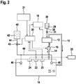
- FIG. 4 shows a further embodiment of the invention in which the inerting device described above from FIG Fig. 1 is combined with a fire extinguishing system for fire fighting.
- the same or corresponding components have the same reference numerals as in FIG Fig. 1 Mistake.
- the inerting device contains in particular at least one metal-air battery 12, which is connected to the volume 11 via a feed channel 14, at least one electrical consumer 18, which is connected to the metal-air battery, and a control device 20.
- the inerting device can also contain an electrolyte container 28, a short-circuit circuit 34, an oxygen sensor 22, a temperature sensor 23 and a fire alarm 24, depending on the embodiment variant.
- the fire extinguishing system has an extinguishing agent tank 40 for holding an extinguishing agent (e.g. extinguishing water, nitrogen, inert gas, water mist or a combination thereof) 42.
- the fire extinguishing system also has an extinguishing agent line 44, which is connected on the one hand to the extinguishing agent tank 40 and on the other hand ends at one or more outlet openings 46 in the interior of the room 10 in order to introduce the liquid extinguishing agent 42 into the room 10 for fire fighting.
- a valve 45 is preferably also arranged in the extinguishing agent line 44 in order to convey the extinguishing agent 42 from the printed extinguishing agent tank 40 to the outlet openings 46 in the space 10. As in Fig. 2 indicated, this valve 45 is preferably also controlled by the control unit 20 of the inerting device. This means that the control unit 20 is a common control unit for the inerting device and the fire extinguishing system.
- Fig. 3 shows an embodiment of the invention analogously Fig. 1 , in which the metal-air battery 12, however, is assigned to a further space 10a having a space volume 11a.
- the room 10a also represents a further air source 13a.
- an oxygen sensor 22a, a temperature sensor 23a and a fire alarm 24a arranged in the room.
- the oxygen sensor 22a and the temperature sensor 23a are connected to the control unit 20 in a wireless or wired manner.
- the fire alarm 24a is connected to the display unit 25 in the cockpit of the aircraft.
- the feed channels 14 and discharge channels 15 are then formed by a pipe system.
- the pipe system has valves 50, 52 through which the space 10, 10a to be inerted or the volume 11, 11a to be inerted can be selected.
- the valves 50, 52 can in particular be controlled with the control unit 20 and can be closed or opened with this.
Landscapes
- Health & Medical Sciences (AREA)
- Public Health (AREA)
- Business, Economics & Management (AREA)
- Emergency Management (AREA)
- Engineering & Computer Science (AREA)
- Chemical & Material Sciences (AREA)
- Aviation & Aerospace Engineering (AREA)
- Electrochemistry (AREA)
- Analytical Chemistry (AREA)
- General Chemical & Material Sciences (AREA)
- Oil, Petroleum & Natural Gas (AREA)
- Chemical Kinetics & Catalysis (AREA)
- Operations Research (AREA)
- Hybrid Cells (AREA)
- Battery Mounting, Suspending (AREA)
Priority Applications (2)
| Application Number | Priority Date | Filing Date | Title |
|---|---|---|---|
| US16/846,872 US11648510B2 (en) | 2019-05-08 | 2020-04-13 | Apparatus and method for inerting a space |
| CN202010375848.8A CN111905302A (zh) | 2019-05-08 | 2020-05-07 | 用于惰化空间的设备和方法 |
Applications Claiming Priority (1)
| Application Number | Priority Date | Filing Date | Title |
|---|---|---|---|
| DE102019003257.8A DE102019003257B4 (de) | 2019-05-08 | 2019-05-08 | Vorrichtung, Verfahren und Verwendung der Vorrichtung zum Inertisieren oder aufrechterhaltung einer Inertisierung eines Raumes sowie Luft- oder Raumfahrzeug |
Publications (2)
| Publication Number | Publication Date |
|---|---|
| EP3736024A1 true EP3736024A1 (fr) | 2020-11-11 |
| EP3736024B1 EP3736024B1 (fr) | 2022-07-06 |
Family
ID=67658335
Family Applications (1)
| Application Number | Title | Priority Date | Filing Date |
|---|---|---|---|
| EP19189345.2A Active EP3736024B1 (fr) | 2019-05-08 | 2019-07-31 | Dispositif et procédé d'inertisation d'un espace |
Country Status (4)
| Country | Link |
|---|---|
| US (1) | US11648510B2 (fr) |
| EP (1) | EP3736024B1 (fr) |
| CN (1) | CN111905302A (fr) |
| DE (1) | DE102019003257B4 (fr) |
Families Citing this family (1)
| Publication number | Priority date | Publication date | Assignee | Title |
|---|---|---|---|---|
| AU2023208810A1 (en) * | 2022-01-19 | 2024-01-25 | Lg Energy Solution, Ltd. | Water injection unit and energy storage system including the same |
Citations (2)
| Publication number | Priority date | Publication date | Assignee | Title |
|---|---|---|---|---|
| WO2007054316A1 (fr) * | 2005-11-10 | 2007-05-18 | Airbus Deutschland Gmbh | Systeme a piles a combustible pour eteindre des feux |
| EP2873443A2 (fr) | 2013-11-13 | 2015-05-20 | Apparatebau Gauting GmbH | Dispositif de protection contre l'incendie et procédé de lutte contre l'incendie |
Family Cites Families (12)
| Publication number | Priority date | Publication date | Assignee | Title |
|---|---|---|---|---|
| US1904828A (en) * | 1930-01-28 | 1933-04-18 | Pawtucket Screw Company | Thermoelectric sprinkler head |
| US2719589A (en) * | 1950-08-03 | 1955-10-04 | Specialties Dev Corp | Fluid dispensing system and apparatus |
| US3019843A (en) * | 1956-07-27 | 1962-02-06 | Powell Dawson | Fire inhibitor and extinguisher |
| US2908334A (en) * | 1957-03-14 | 1959-10-13 | Union Carbide Corp | Process and apparatus for generating and discharging foam |
| US3174550A (en) * | 1961-08-22 | 1965-03-23 | Jet Set Ltd | Method and apparatus for rendering aviation fuel from a flowable to a non-flowable state |
| US3217456A (en) * | 1962-10-12 | 1965-11-16 | United States Gypsum Co | Structural member with multi-layered gypsum board fire protection |
| IL107930A0 (en) | 1993-12-07 | 1994-04-12 | Electric Fuel Ltd | A metal-air battery-powered electric vehicle |
| US20020040940A1 (en) * | 1998-03-18 | 2002-04-11 | Wagner Ernst Werner | Inerting method and apparatus for preventing and extinguishing fires in enclosed spaces |
| EP2302728A1 (fr) | 2009-09-09 | 2011-03-30 | BAE Systems PLC | Générateur de produits gazeux |
| WO2015076172A1 (fr) | 2013-11-19 | 2015-05-28 | 古河電池株式会社 | Batterie métal-air et unité de batterie métal-air |
| DE102014208044A1 (de) | 2014-04-29 | 2015-10-29 | Mahle International Gmbh | Metall-Luft-Batterie |
| US20180148188A1 (en) * | 2016-08-03 | 2018-05-31 | Hamilton Sundstrand Corporation | Catalytic fuel tank inerting apparatus for aircraft |
-
2019
- 2019-05-08 DE DE102019003257.8A patent/DE102019003257B4/de active Active
- 2019-07-31 EP EP19189345.2A patent/EP3736024B1/fr active Active
-
2020
- 2020-04-13 US US16/846,872 patent/US11648510B2/en active Active
- 2020-05-07 CN CN202010375848.8A patent/CN111905302A/zh active Pending
Patent Citations (2)
| Publication number | Priority date | Publication date | Assignee | Title |
|---|---|---|---|---|
| WO2007054316A1 (fr) * | 2005-11-10 | 2007-05-18 | Airbus Deutschland Gmbh | Systeme a piles a combustible pour eteindre des feux |
| EP2873443A2 (fr) | 2013-11-13 | 2015-05-20 | Apparatebau Gauting GmbH | Dispositif de protection contre l'incendie et procédé de lutte contre l'incendie |
Also Published As
| Publication number | Publication date |
|---|---|
| US11648510B2 (en) | 2023-05-16 |
| DE102019003257A1 (de) | 2020-11-12 |
| EP3736024B1 (fr) | 2022-07-06 |
| DE102019003257B4 (de) | 2020-12-17 |
| US20200353406A1 (en) | 2020-11-12 |
| CN111905302A (zh) | 2020-11-10 |
Similar Documents
| Publication | Publication Date | Title |
|---|---|---|
| DE102012002131A1 (de) | Notfallversorgungssystem für ein Verkehrsmittel,Verfahren zum Bereitstellen von elektrischer Leistung und zum Unterdrücken von Feuer und Flugzeug mit einem Notfallversorgungssystem | |
| EP1476226B1 (fr) | Protection contre l'incendie | |
| DE102009054886A1 (de) | Brandschutzsystem, Luft- oder Raumfahrzeug sowie Verfahren zum Eindämmen und Unterdrücken eines Brandes | |
| DE102019003257B4 (de) | Vorrichtung, Verfahren und Verwendung der Vorrichtung zum Inertisieren oder aufrechterhaltung einer Inertisierung eines Raumes sowie Luft- oder Raumfahrzeug | |
| EP3105368A1 (fr) | Alimentation sans interruption d'une installation d'électrolyse | |
| EP1796960A1 (fr) | Aeronef a systeme d'avertissement de pression differentielle cabine | |
| EP2742556B1 (fr) | Traitement de l'air de la cabine d'un aéronef | |
| EP3191195A1 (fr) | Procédé permettant de faire fonctionner un dispositif servant à maîtriser un incendie ou un dégagement de substance, en particulier pour des batteries au lithium | |
| DE19531916C2 (de) | Verfahren und Vorrichtung zur Bereitstellung von Atemgas in Notsauerstoffsystemen | |
| DE102013003128B4 (de) | Gefechtsfahrzeug mit einer Brandunterdrückungsanlage | |
| DE202021105353U1 (de) | Fahrzeug mit Brandschutzeinheit für Brennstoffzellen | |
| DE102021005307A1 (de) | Vorrichtung zum Verschweißen der elektrischen Kontakte einer Batterie | |
| EP1717141B1 (fr) | Sous-marin avec piles à combustible | |
| DE3804659C2 (fr) | ||
| AT5999U1 (de) | Mobiles system zur speicherung von einem flüssigen leichten gas, insbesondere wasserstoff | |
| EP1936726A1 (fr) | Agencement de cellules de combustible et procédé de fonctionnement d'une cellule de combustible | |
| DE102014007013A1 (de) | Verfahren zum Aufheizen eines Katalysators | |
| WO2024042180A2 (fr) | Boîtier d'accumulateur pour un véhicule ferroviaire | |
| EP3489061B1 (fr) | Système de réservoir pour un véhicule | |
| DE102005019052A1 (de) | Sauerstoffversorgungsvorrichtung | |
| DE102004046501B4 (de) | Vorrichtung und Verfahren zur Risikominimierung für Brennstofftanks von Luftfahrzeugen | |
| DE102014210032B4 (de) | Brandschutzeinrichtung zum Absenken einer Luftsauerstoffkonzentration in einem Schutzbereich eines Gebäudes | |
| DE102015225658A1 (de) | Brennstoffzelle | |
| WO2026104049A1 (fr) | Dispositif d'entraînement pour aéronef comportant un dispositif de pile à combustible | |
| EP4570964A1 (fr) | Dispositif de rinçage destiné au stockage intermédiaire d'un milieu gazeux provenant d'un processus de rinçage |
Legal Events
| Date | Code | Title | Description |
|---|---|---|---|
| PUAI | Public reference made under article 153(3) epc to a published international application that has entered the european phase |
Free format text: ORIGINAL CODE: 0009012 |
|
| STAA | Information on the status of an ep patent application or granted ep patent |
Free format text: STATUS: THE APPLICATION HAS BEEN PUBLISHED |
|
| AK | Designated contracting states |
Kind code of ref document: A1 Designated state(s): AL AT BE BG CH CY CZ DE DK EE ES FI FR GB GR HR HU IE IS IT LI LT LU LV MC MK MT NL NO PL PT RO RS SE SI SK SM TR |
|
| AX | Request for extension of the european patent |
Extension state: BA ME |
|
| STAA | Information on the status of an ep patent application or granted ep patent |
Free format text: STATUS: REQUEST FOR EXAMINATION WAS MADE |
|
| 17P | Request for examination filed |
Effective date: 20201211 |
|
| RBV | Designated contracting states (corrected) |
Designated state(s): AL AT BE BG CH CY CZ DE DK EE ES FI FR GB GR HR HU IE IS IT LI LT LU LV MC MK MT NL NO PL PT RO RS SE SI SK SM TR |
|
| STAA | Information on the status of an ep patent application or granted ep patent |
Free format text: STATUS: EXAMINATION IS IN PROGRESS |
|
| 17Q | First examination report despatched |
Effective date: 20210226 |
|
| GRAP | Despatch of communication of intention to grant a patent |
Free format text: ORIGINAL CODE: EPIDOSNIGR1 |
|
| STAA | Information on the status of an ep patent application or granted ep patent |
Free format text: STATUS: GRANT OF PATENT IS INTENDED |
|
| INTG | Intention to grant announced |
Effective date: 20220426 |
|
| GRAS | Grant fee paid |
Free format text: ORIGINAL CODE: EPIDOSNIGR3 |
|
| GRAA | (expected) grant |
Free format text: ORIGINAL CODE: 0009210 |
|
| STAA | Information on the status of an ep patent application or granted ep patent |
Free format text: STATUS: THE PATENT HAS BEEN GRANTED |
|
| AK | Designated contracting states |
Kind code of ref document: B1 Designated state(s): AL AT BE BG CH CY CZ DE DK EE ES FI FR GB GR HR HU IE IS IT LI LT LU LV MC MK MT NL NO PL PT RO RS SE SI SK SM TR |
|
| REG | Reference to a national code |
Ref country code: AT Ref legal event code: REF Ref document number: 1502445 Country of ref document: AT Kind code of ref document: T Effective date: 20220715 Ref country code: CH Ref legal event code: EP |
|
| REG | Reference to a national code |
Ref country code: DE Ref legal event code: R096 Ref document number: 502019004862 Country of ref document: DE |
|
| REG | Reference to a national code |
Ref country code: IE Ref legal event code: FG4D Free format text: LANGUAGE OF EP DOCUMENT: GERMAN |
|
| REG | Reference to a national code |
Ref country code: LT Ref legal event code: MG9D |
|
| REG | Reference to a national code |
Ref country code: NL Ref legal event code: MP Effective date: 20220706 |
|
| PG25 | Lapsed in a contracting state [announced via postgrant information from national office to epo] |
Ref country code: SE Free format text: LAPSE BECAUSE OF FAILURE TO SUBMIT A TRANSLATION OF THE DESCRIPTION OR TO PAY THE FEE WITHIN THE PRESCRIBED TIME-LIMIT Effective date: 20220706 Ref country code: RS Free format text: LAPSE BECAUSE OF FAILURE TO SUBMIT A TRANSLATION OF THE DESCRIPTION OR TO PAY THE FEE WITHIN THE PRESCRIBED TIME-LIMIT Effective date: 20220706 Ref country code: PT Free format text: LAPSE BECAUSE OF FAILURE TO SUBMIT A TRANSLATION OF THE DESCRIPTION OR TO PAY THE FEE WITHIN THE PRESCRIBED TIME-LIMIT Effective date: 20221107 Ref country code: NO Free format text: LAPSE BECAUSE OF FAILURE TO SUBMIT A TRANSLATION OF THE DESCRIPTION OR TO PAY THE FEE WITHIN THE PRESCRIBED TIME-LIMIT Effective date: 20221006 Ref country code: NL Free format text: LAPSE BECAUSE OF FAILURE TO SUBMIT A TRANSLATION OF THE DESCRIPTION OR TO PAY THE FEE WITHIN THE PRESCRIBED TIME-LIMIT Effective date: 20220706 Ref country code: LV Free format text: LAPSE BECAUSE OF FAILURE TO SUBMIT A TRANSLATION OF THE DESCRIPTION OR TO PAY THE FEE WITHIN THE PRESCRIBED TIME-LIMIT Effective date: 20220706 Ref country code: LT Free format text: LAPSE BECAUSE OF FAILURE TO SUBMIT A TRANSLATION OF THE DESCRIPTION OR TO PAY THE FEE WITHIN THE PRESCRIBED TIME-LIMIT Effective date: 20220706 Ref country code: FI Free format text: LAPSE BECAUSE OF FAILURE TO SUBMIT A TRANSLATION OF THE DESCRIPTION OR TO PAY THE FEE WITHIN THE PRESCRIBED TIME-LIMIT Effective date: 20220706 Ref country code: ES Free format text: LAPSE BECAUSE OF FAILURE TO SUBMIT A TRANSLATION OF THE DESCRIPTION OR TO PAY THE FEE WITHIN THE PRESCRIBED TIME-LIMIT Effective date: 20220706 |
|
| PG25 | Lapsed in a contracting state [announced via postgrant information from national office to epo] |
Ref country code: PL Free format text: LAPSE BECAUSE OF FAILURE TO SUBMIT A TRANSLATION OF THE DESCRIPTION OR TO PAY THE FEE WITHIN THE PRESCRIBED TIME-LIMIT Effective date: 20220706 Ref country code: IS Free format text: LAPSE BECAUSE OF FAILURE TO SUBMIT A TRANSLATION OF THE DESCRIPTION OR TO PAY THE FEE WITHIN THE PRESCRIBED TIME-LIMIT Effective date: 20221106 Ref country code: HR Free format text: LAPSE BECAUSE OF FAILURE TO SUBMIT A TRANSLATION OF THE DESCRIPTION OR TO PAY THE FEE WITHIN THE PRESCRIBED TIME-LIMIT Effective date: 20220706 Ref country code: GR Free format text: LAPSE BECAUSE OF FAILURE TO SUBMIT A TRANSLATION OF THE DESCRIPTION OR TO PAY THE FEE WITHIN THE PRESCRIBED TIME-LIMIT Effective date: 20221007 |
|
| REG | Reference to a national code |
Ref country code: CH Ref legal event code: PL |
|
| REG | Reference to a national code |
Ref country code: BE Ref legal event code: MM Effective date: 20220731 |
|
| REG | Reference to a national code |
Ref country code: DE Ref legal event code: R097 Ref document number: 502019004862 Country of ref document: DE |
|
| PG25 | Lapsed in a contracting state [announced via postgrant information from national office to epo] |
Ref country code: SM Free format text: LAPSE BECAUSE OF FAILURE TO SUBMIT A TRANSLATION OF THE DESCRIPTION OR TO PAY THE FEE WITHIN THE PRESCRIBED TIME-LIMIT Effective date: 20220706 Ref country code: RO Free format text: LAPSE BECAUSE OF FAILURE TO SUBMIT A TRANSLATION OF THE DESCRIPTION OR TO PAY THE FEE WITHIN THE PRESCRIBED TIME-LIMIT Effective date: 20220706 Ref country code: MC Free format text: LAPSE BECAUSE OF FAILURE TO SUBMIT A TRANSLATION OF THE DESCRIPTION OR TO PAY THE FEE WITHIN THE PRESCRIBED TIME-LIMIT Effective date: 20220706 Ref country code: LU Free format text: LAPSE BECAUSE OF NON-PAYMENT OF DUE FEES Effective date: 20220731 Ref country code: LI Free format text: LAPSE BECAUSE OF NON-PAYMENT OF DUE FEES Effective date: 20220731 Ref country code: DK Free format text: LAPSE BECAUSE OF FAILURE TO SUBMIT A TRANSLATION OF THE DESCRIPTION OR TO PAY THE FEE WITHIN THE PRESCRIBED TIME-LIMIT Effective date: 20220706 Ref country code: CZ Free format text: LAPSE BECAUSE OF FAILURE TO SUBMIT A TRANSLATION OF THE DESCRIPTION OR TO PAY THE FEE WITHIN THE PRESCRIBED TIME-LIMIT Effective date: 20220706 Ref country code: CH Free format text: LAPSE BECAUSE OF NON-PAYMENT OF DUE FEES Effective date: 20220731 |
|
| PLBE | No opposition filed within time limit |
Free format text: ORIGINAL CODE: 0009261 |
|
| STAA | Information on the status of an ep patent application or granted ep patent |
Free format text: STATUS: NO OPPOSITION FILED WITHIN TIME LIMIT |
|
| PG25 | Lapsed in a contracting state [announced via postgrant information from national office to epo] |
Ref country code: SK Free format text: LAPSE BECAUSE OF FAILURE TO SUBMIT A TRANSLATION OF THE DESCRIPTION OR TO PAY THE FEE WITHIN THE PRESCRIBED TIME-LIMIT Effective date: 20220706 Ref country code: EE Free format text: LAPSE BECAUSE OF FAILURE TO SUBMIT A TRANSLATION OF THE DESCRIPTION OR TO PAY THE FEE WITHIN THE PRESCRIBED TIME-LIMIT Effective date: 20220706 Ref country code: BE Free format text: LAPSE BECAUSE OF NON-PAYMENT OF DUE FEES Effective date: 20220731 |
|
| 26N | No opposition filed |
Effective date: 20230411 |
|
| PG25 | Lapsed in a contracting state [announced via postgrant information from national office to epo] |
Ref country code: AL Free format text: LAPSE BECAUSE OF FAILURE TO SUBMIT A TRANSLATION OF THE DESCRIPTION OR TO PAY THE FEE WITHIN THE PRESCRIBED TIME-LIMIT Effective date: 20220706 |
|
| PG25 | Lapsed in a contracting state [announced via postgrant information from national office to epo] |
Ref country code: IE Free format text: LAPSE BECAUSE OF NON-PAYMENT OF DUE FEES Effective date: 20220731 |
|
| PG25 | Lapsed in a contracting state [announced via postgrant information from national office to epo] |
Ref country code: SI Free format text: LAPSE BECAUSE OF FAILURE TO SUBMIT A TRANSLATION OF THE DESCRIPTION OR TO PAY THE FEE WITHIN THE PRESCRIBED TIME-LIMIT Effective date: 20220706 |
|
| PG25 | Lapsed in a contracting state [announced via postgrant information from national office to epo] |
Ref country code: IT Free format text: LAPSE BECAUSE OF FAILURE TO SUBMIT A TRANSLATION OF THE DESCRIPTION OR TO PAY THE FEE WITHIN THE PRESCRIBED TIME-LIMIT Effective date: 20220706 |
|
| GBPC | Gb: european patent ceased through non-payment of renewal fee |
Effective date: 20230731 |
|
| PG25 | Lapsed in a contracting state [announced via postgrant information from national office to epo] |
Ref country code: MK Free format text: LAPSE BECAUSE OF FAILURE TO SUBMIT A TRANSLATION OF THE DESCRIPTION OR TO PAY THE FEE WITHIN THE PRESCRIBED TIME-LIMIT Effective date: 20220706 Ref country code: CY Free format text: LAPSE BECAUSE OF FAILURE TO SUBMIT A TRANSLATION OF THE DESCRIPTION OR TO PAY THE FEE WITHIN THE PRESCRIBED TIME-LIMIT Effective date: 20220706 Ref country code: GB Free format text: LAPSE BECAUSE OF NON-PAYMENT OF DUE FEES Effective date: 20230731 |
|
| PG25 | Lapsed in a contracting state [announced via postgrant information from national office to epo] |
Ref country code: HU Free format text: LAPSE BECAUSE OF FAILURE TO SUBMIT A TRANSLATION OF THE DESCRIPTION OR TO PAY THE FEE WITHIN THE PRESCRIBED TIME-LIMIT; INVALID AB INITIO Effective date: 20190731 |
|
| PG25 | Lapsed in a contracting state [announced via postgrant information from national office to epo] |
Ref country code: BG Free format text: LAPSE BECAUSE OF FAILURE TO SUBMIT A TRANSLATION OF THE DESCRIPTION OR TO PAY THE FEE WITHIN THE PRESCRIBED TIME-LIMIT Effective date: 20220706 |
|
| PG25 | Lapsed in a contracting state [announced via postgrant information from national office to epo] |
Ref country code: MT Free format text: LAPSE BECAUSE OF FAILURE TO SUBMIT A TRANSLATION OF THE DESCRIPTION OR TO PAY THE FEE WITHIN THE PRESCRIBED TIME-LIMIT Effective date: 20220706 |
|
| REG | Reference to a national code |
Ref country code: AT Ref legal event code: MM01 Ref document number: 1502445 Country of ref document: AT Kind code of ref document: T Effective date: 20240731 |
|
| PGFP | Annual fee paid to national office [announced via postgrant information from national office to epo] |
Ref country code: DE Payment date: 20250904 Year of fee payment: 7 |
|
| PG25 | Lapsed in a contracting state [announced via postgrant information from national office to epo] |
Ref country code: AT Free format text: LAPSE BECAUSE OF NON-PAYMENT OF DUE FEES Effective date: 20240731 |
|
| PGFP | Annual fee paid to national office [announced via postgrant information from national office to epo] |
Ref country code: FR Payment date: 20250725 Year of fee payment: 7 |
|
| PG25 | Lapsed in a contracting state [announced via postgrant information from national office to epo] |
Ref country code: TR Free format text: LAPSE BECAUSE OF FAILURE TO SUBMIT A TRANSLATION OF THE DESCRIPTION OR TO PAY THE FEE WITHIN THE PRESCRIBED TIME-LIMIT Effective date: 20220706 |
|
| PGFP | Annual fee paid to national office [announced via postgrant information from national office to epo] |
Ref country code: AT Payment date: 20260410 Year of fee payment: 5 |