EP3736032B1 - Rohrverschraubungen mit filter - Google Patents
Rohrverschraubungen mit filter Download PDFInfo
- Publication number
- EP3736032B1 EP3736032B1 EP19173398.9A EP19173398A EP3736032B1 EP 3736032 B1 EP3736032 B1 EP 3736032B1 EP 19173398 A EP19173398 A EP 19173398A EP 3736032 B1 EP3736032 B1 EP 3736032B1
- Authority
- EP
- European Patent Office
- Prior art keywords
- filter
- orifice
- connection pipe
- driven section
- receiving orifice
- Prior art date
- Legal status (The legal status is an assumption and is not a legal conclusion. Google has not performed a legal analysis and makes no representation as to the accuracy of the status listed.)
- Active
Links
Images



Classifications
-
- B—PERFORMING OPERATIONS; TRANSPORTING
- B01—PHYSICAL OR CHEMICAL PROCESSES OR APPARATUS IN GENERAL
- B01D—SEPARATION
- B01D35/00—Filtering devices having features not specifically covered by groups B01D24/00 - B01D33/00, or for applications not specifically covered by groups B01D24/00 - B01D33/00; Auxiliary devices for filtration; Filter housing constructions
- B01D35/02—Filters adapted for location in special places, e.g. pipe-lines, pumps, stop-cocks
- B01D35/023—Filler pipe filters
-
- B—PERFORMING OPERATIONS; TRANSPORTING
- B01—PHYSICAL OR CHEMICAL PROCESSES OR APPARATUS IN GENERAL
- B01D—SEPARATION
- B01D35/00—Filtering devices having features not specifically covered by groups B01D24/00 - B01D33/00, or for applications not specifically covered by groups B01D24/00 - B01D33/00; Auxiliary devices for filtration; Filter housing constructions
- B01D35/05—Floating filters
-
- E—FIXED CONSTRUCTIONS
- E03—WATER SUPPLY; SEWERAGE
- E03B—INSTALLATIONS OR METHODS FOR OBTAINING, COLLECTING, OR DISTRIBUTING WATER
- E03B7/00—Water main or service pipe systems
- E03B7/07—Arrangement of devices, e.g. filters, flow controls, measuring devices, siphons or valves, in the pipe systems
-
- B—PERFORMING OPERATIONS; TRANSPORTING
- B01—PHYSICAL OR CHEMICAL PROCESSES OR APPARATUS IN GENERAL
- B01D—SEPARATION
- B01D2201/00—Details relating to filtering apparatus
- B01D2201/04—Supports for the filtering elements
- B01D2201/0415—Details of supporting structures
- B01D2201/0423—Details of supporting structures not in the inner side of the cylindrical filtering elements
-
- B—PERFORMING OPERATIONS; TRANSPORTING
- B01—PHYSICAL OR CHEMICAL PROCESSES OR APPARATUS IN GENERAL
- B01D—SEPARATION
- B01D2201/00—Details relating to filtering apparatus
- B01D2201/24—Tools used for the removal of filters
-
- B—PERFORMING OPERATIONS; TRANSPORTING
- B01—PHYSICAL OR CHEMICAL PROCESSES OR APPARATUS IN GENERAL
- B01D—SEPARATION
- B01D2201/00—Details relating to filtering apparatus
- B01D2201/30—Filter housing constructions
- B01D2201/301—Details of removable closures, lids, caps, filter heads
- B01D2201/302—Details of removable closures, lids, caps, filter heads having inlet or outlet ports
- B01D2201/303—Details of removable closures, lids, caps, filter heads having inlet or outlet ports not arranged concentrically
-
- B—PERFORMING OPERATIONS; TRANSPORTING
- B01—PHYSICAL OR CHEMICAL PROCESSES OR APPARATUS IN GENERAL
- B01D—SEPARATION
- B01D2201/00—Details relating to filtering apparatus
- B01D2201/30—Filter housing constructions
- B01D2201/301—Details of removable closures, lids, caps, filter heads
- B01D2201/306—Closures, lids, caps or filter heads forming one element with the filtering element
-
- B—PERFORMING OPERATIONS; TRANSPORTING
- B01—PHYSICAL OR CHEMICAL PROCESSES OR APPARATUS IN GENERAL
- B01D—SEPARATION
- B01D2201/00—Details relating to filtering apparatus
- B01D2201/40—Special measures for connecting different parts of the filter
- B01D2201/4015—Bayonet connecting means
Definitions
- the present disclosure relates to pipe fittings with a filter.
- Conventional pipe fittings are applied to filter fluid between at least one connection pipe so as to avoid a block of impurities of the fluid in an inlet of a washing machine, an outlet of a faucet, and a drawing end of a pump by ways of a filter.
- the pipe fittings contain two water connectors, one of which is accommodated in a holding disc configured to flow the fluid, wherein the holding disc has a semispherical filter, and the two water connectors are mounted by screwing at least one nut with threads of the two water connectors, wherein two seal gaskets are fixed on two screwing portions of the two water connectors respectively.
- a size of the filter is limited by the at least one connection pipe, thus reducing filtration efficiency.
- the filter is removed after unscrewing the at least one nut by using a wrench.
- Patent application publication EP 0207233 A1 discloses a stop valve comprising a rotatable plug member that has three basic modes. Two of them are the standard modes of a valve, namely a first mode in which a fluid can pass the valve and a second mode in which the through-flow is blocked. A further mode allows for the filter arranged on the plug and filtering the fluid in the first mode to be cleaned by removing particulate matter deposited on the filter surface.
- the plug is attached on the valve's housing by means of a resilient member extending from the plug along the plug's axis of rotation and being provided with a bulb portion. The resilient member is inserted into an end wall opening, thereby preventing the plug from being easily detached from the housing of the valve.
- an indexing tab extends axially from the end face of the plug and into an arcuate slot formed in the inner surface of the housing so that the rotation of the plug is limited by the length of said arcuate slot.
- a primary aspect of the present invention is to provide pipe fittings with a filter which filters fluid flowing between the first connection pipe and the second connection pipe.
- Secondary aspect of the present invention is to provide pipe fittings with a filter which removes the filter easily.
- Further aspect of the present invention is to provide pipe fittings with a filter which contains the filter of large size.
- Another aspect of the present invention is to provide pipe fittings with a filter which replaces the filter easily.
- pipe fittings with a filter contains: a body, a filter valve, and two seal gaskets.
- the body includes a first connection pipe and a second connection pipe which are connected on two ends of the body respectively, a receiving orifice defined between and communicating with the first connection pipe and the second connection pipe, and at least one guide slot formed on the receiving orifice.
- the receiving orifice is cylindrical and has at least one opening defined on one of two ends of the receiving orifice.
- the filter valve includes a driven section and an operation portion arranged on an end of the driven section.
- the two seal gaskets are accommodated in a first peripheral groove and a second peripheral groove respectively.
- the driven section has the first peripheral groove, the second peripheral groove which are defined on two sides of the driven section respectively, and a filtration orifice defined between the first peripheral groove and the second peripheral groove and communicating with the driven section, and at least one fixing bolt mounted between the operation portion and the first peripheral groove and extending outward from the driven section.
- the at least one fixing bolt slides into the at least one guide slot respectively so that the filter valve is accommodated in the receiving orifice.
- the at least one guide slot is formed on the at least one opening of the receiving orifice.
- the filter is accommodated in the filtration orifice of the driven section, such that fluid flows between the first connection pipe and the second connection pipe and is filtered by the filter.
- the receiving orifice has two guide slots formed on two sides of the at least one opening of the receiving orifice, and the two guide slots correspond to two fixing bolts Individually.
- the at least one guide slot accommodates at least one positioning projection adjacent to at least one bottom of the at least one guide slot respectively so as to stop a removal of the at least one fixing bolt.
- the filter is removably accommodated in the filtration orifice.
- the filtration orifice has at least one support rib configured to support the filter.
- the filtration orifice has multiple horizontal support ribs and multiple vertical support ribs perpendicular to the multiple horizontal support ribs.
- the receiving orifice has a recess defined on at least one opening of one of two ends of the receiving orifice adjacent to the second connection pipe.
- the filter is one-piece formed in the filtration orifice.
- a diameter of the driven section is more than that of a connection portion between the first connection pipe and the second connection pipe.
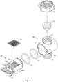
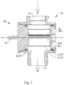
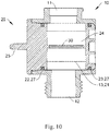
- pipe fittings with a filter at least comprises: a body 10, a filter valve 20, two seal gaskets 27, and the filter 30.
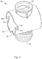
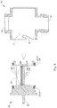
- the body 10 includes a first connection pipe 11 and a second connection pipe 12 which are connected on two ends of the body 10 respectively, a receiving orifice 13 defined between and communicating with the first connection pipe 11 and the second connection pipe 12, and at least one guide slot 14 formed on the receiving orifice 13.
- the first connection pipe 11 and the second connection pipe 12 are in communication with each other in the body 10 and are connected with other pipes respectively.
- the first connection pipe 11 is hollow and is connected with a water connector 40 having a screw nut
- the water connector 40 is connected with a first flow pipe having a threaded section, wherein the water connector 40 has a leak-proof rubber 41 accommodated therein.
- the second connection pipe 12 has outer threads formed on an outer wall thereof so as to screw with a screw nut of a second flow pipe.
- the receiving orifice 13 is perpendicular to the first connection pipe 11 and the second connection pipe 12, and the first connection pipe 11, the second connection pipe 12 and the receiving orifice 13 are injection molded or are machined by ways of a mold.
- the receiving orifice 13 is cylindrical and has at least one opening defined on one of two ends of the receiving orifice 13, and the receiving orifice 13 has the at least one guide slot 14 formed on the at least one opening of the one end of the receiving orifice 13.
- the receiving orifice 13 has two guide slots 14 formed on the at least one opening of the one end of the receiving orifice 13 proximate to the first connection pipe 11, and the receiving orifice 13 has a recess 15 defined the at least one opening of the one end of the receiving orifice 13 adjacent to the second connection pipe 12.
- the filter valve 20 includes a driven section 21 and an operation portion 25 arranged on an end of the driven section 21, wherein the operation portion 25 is any one of a lever, a rotary button, and a spherical knob so as to be manually operated by a user, such that the driven section 21 is driven by the operation portion 25 to be pushed into or to be pulled out of the receiving orifice 13.
- a diameter of the driven section 21 is more than that of a connection portion between the first connection pipe 11 and the second connection pipe 12, such that the filter 30 is accommodated in the driven section 21 so as to enhance filtration efficiency.
- the driven section 21 has a first peripheral groove 22, a second peripheral groove 23 which are defined on two sides of the driven section 21 respectively, and a filtration orifice 24 defined between the first peripheral groove 22 and the second peripheral groove 23 and communicating with the driven section 21, wherein the filtration orifice is square or is in other shapes.
- At least one fixing bolt 26 is mounted between the operation portion 25 and the first peripheral groove 22 and extends outward from the driven section 21, the at least one guide slot 14 is open, and the at least one guide slot 14 is tilted or is arcuate. In this embodiment, the at least one guide slot 14 is open and is arcuate.
- the operation portion 25 is operated manually to drive the at least one fixing bolt 26 to slide into a distal end of the at least one guide slot 14 so that the filter valve 20 is fixed in the receiving orifice 13.
- the driven section 21 has two bolts 26 corresponding to the two guide slots 14 respectively, and the driven section 21 has a protrusion 28 formed between the two bolts 26 and corresponding to the recess 15.
- the driven section 21 is cylindrical. In another embodiment, the driven section 21 is conical so as to match with the receiving orifice 13 which is conical, and the driven section 21 is moved in receiving orifice 13 matingly.
- the two seal gaskets 27 are accommodated in the first peripheral groove 22 and the second peripheral groove 23 respectively, and the filter 30 is removably accommodated in the filtration orifice 24 of the driven section 21, such that fluid flows between the first connection pipe 11 and the second connection pipe 12 and is filtered by the filter 30, and the filter 30 is removed easily by ways of the operation portion 25.
- the receiving orifice 13 has a guide slot 14 formed on the at least one opening of the one end of the receiving orifice 13 proximate to the first connection pipe 11, and the driven section 21 has a bolt 26 corresponding to the guide slot 14 so as to avoid a removal of the driven section 21 from the receiving orifice 13.
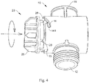
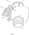
- the driven section 21 is inserted into the receiving orifice 13 of the body 10, the at least one fixing bolt 26 is aligned with the at least one guide slot 14, and the operation portion 25 is manually rotated so that the at least one fixing bolt 26 is guided by the at least one guide slot 14 to move into the driven section 21, hence the filter valve 20 is accommodated in the receiving orifice 13.
- the at least one guide slot 14 accommodates at least one positioning projection 141 adjacent to at least one bottom of the at least one guide slot 14 respectively so as to stop a removal of the at least one fixing bolt 26.
- the filter 30 is accommodated and is adhered in the filtration orifice 24 of the driven section 21 by using adhesive or high frequency equipment.
- the filter 30 is removably accommodated in the filtration orifice 24 so as to be replaced.
- the filtration orifice 24 has at least one support rib configured to support the filter 20, thus fixing the filter 30 in the filtration orifice 24 securely.
- the filtration orifice 24 has multiple horizontal support ribs 241 and multiple vertical support ribs 242 perpendicular to the multiple horizontal support ribs 241, wherein multiple slits are defined among the multiple horizontal support ribs 241 and the multiple vertical support ribs 242 individually so that the fluid flows through the multiple slits, and the filter 30 is removably accommodated in the filtration orifice 24.
- the receiving orifice 13 has the recess 15, and the driven section 21 has the protrusion 28 extending outward from the driven section 21 and located between the operation portion 25 and the first peripheral groove 22 so that the protrusion 28 corresponds to and engages with the recess 15, thus fixing the filter 30 in the receiving orifice 13 in a correct direction.
- the operation portion 25 is rotated so that the at least one fixing bolt 26 moves across the at least one positioning projection 141 and slides out of the at least one guide slot 14, the driven section 21 is removed from the receiving orifice 13, and the filter 30 is detachable so as to eliminate the impurities 50 from the filter 30. Thereafter, the filter 30 is fixed in the receiving orifice 13 by rotating the operation portion 25 after being cleaned.
- the filter 30 is one-piece formed in the filtration orifice 24.
- the filter 30 is injection molded from plastic material with the filtration orifice 24 so as to eliminate the protrusion 28 and the recess 15, thus reducing fabrication cost.
Landscapes
- Engineering & Computer Science (AREA)
- Water Supply & Treatment (AREA)
- Chemical & Material Sciences (AREA)
- Chemical Kinetics & Catalysis (AREA)
- Health & Medical Sciences (AREA)
- Life Sciences & Earth Sciences (AREA)
- Hydrology & Water Resources (AREA)
- Public Health (AREA)
- Filtration Of Liquid (AREA)
Claims (10)
- Rohrverschraubungen mit einem Filter (30), umfassend:einen Körper (10), der eine erste Anschlussleitung (11) und eine zweite Anschlussleitung (12), die jeweils an zwei Enden des Körpers (10) verbunden sind, eine Aufnahmeöffnung (13), die zwischen der ersten Anschlussleitung (11) und der zweiten Anschlussleitung (12) definiert ist und mit diesen in Verbindung steht, und mindestens einen Führungsschlitz (14), der an der Aufnahmeöffnung (13) ausgebildet ist, beinhaltet, wobei die Aufnahmeöffnung (13) zylinderförmig ist und mindestens eine Öffnung aufweist, die an einem der zwei Enden der Aufnahmeöffnung (13) definiert ist,ein Filterventil (20), das eine Antriebssektion (21) und einen Betätigungsabschnitt (25), der an einem Ende der Antriebssektion (21) angeordnet ist, beinhaltet undzwei Dichtungsscheiben (27), die entsprechend in einer ersten Umfangsnut (22) und einer zweiten Umfangsnut (23) aufgenommen sind,wobei die Antriebssektion (21) die erste Umfangsnut (22), die zweite Umfangsnut (23), die entsprechend an zwei Seiten der Antriebssektion (21) definiert sind, und eine Filtrationsöffnung (24) aufweist, die zwischen der ersten Umfangsnut (22) und der zweiten Umfangsnut (23) definiert ist und mit der Antriebssektion (21) in Verbindung steht,dadurch gekennzeichnet, dassmindestens ein Befestigungsbolzen (26) zwischen dem Betätigungsabschnitt (25) und der ersten Umfangsnut (22) montiert ist und sich von der Antriebssektion (21) nach außen erstreckt, wobei der mindestens eine Befestigungsbolzen (26) entsprechend in den mindestens einen Führungsschlitz (14) gleitet, sodass das Filterventil (20) in der Aufnahmeöffnung (13) aufgenommen ist,wobei der mindestens eine Führungsschlitz (14) an der mindestens einen Öffnung der Aufnahmeöffnung (13) ausgebildet ist.
- Rohrverschraubung nach Anspruch 1, dadurch gekennzeichnet, dass der Filter (30) in der Filtrationsöffnung (24) der Antriebssektion (21) aufgenommen ist, sodass Fluid zwischen der ersten Anschlussleitung (11) und der zweiten Anschlussleitung(12) strömt und durch den Filter (30) filtriert wird.
- Rohrverschraubung nach Anspruch 1, dadurch gekennzeichnet, dass die Aufnahmeöffnung (13) zwei Führungsschlitze (14) aufweist, die an zwei Seiten der mindestens einen Öffnung der Aufnahmeöffnung (13) ausgebildet sind, und die beiden Führungsschlitze (14) individuell mit den zwei Befestigungsbolzen (26) korrespondieren.
- Rohrverschraubung nach Anspruch 1, dadurch gekennzeichnet, dass der mindestens eine Führungsschlitz (14) mindestens einen Positionierungsvorsprung (141) benachbart zu mindestens einem Boden des mindestens einen Führungsschlitzes (14) entsprechend aufnimmt, um ein Entfernen des mindestens einen Befestigungsbolzens (26) zu stoppen.
- Rohrverschraubung nach Anspruch 2, dadurch gekennzeichnet, dass der Filter (30) entfernbar in der Filtrationsöffnung (24) aufgenommen ist.
- Rohrverschraubung nach Anspruch 5, dadurch gekennzeichnet, dass die Filtrationsöffnung (24) mindestens eine Stützrippe aufweist, die zum Stützen des Filters (20) konfiguriert ist.
- Rohrverschraubung nach Anspruch 6, dadurch gekennzeichnet, dass die Filtrationsöffnung (24) mehrere horizontale Stützrippen (241) und mehrere vertikale Stützrippen (242) senkrecht zu den mehreren horizontalen Stützrippen (241) aufweist.
- Rohrverschraubung nach Anspruch 6, dadurch gekennzeichnet, dass die Aufnahmeöffnung (13) eine Aussparung (15) aufweist, die an mindestens einer Öffnung von einem von zwei Enden der Aufnahmeöffnung (13) benachbart zu der zweiten Anschlussleitung (12) definiert ist.
- Rohrverschraubung nach Anspruch 2, dadurch gekennzeichnet, dass der Filter (30) einteilig in der Filtrationsöffnung (24) ausgebildet ist.
- Rohrverschraubung nach Anspruch 1, dadurch gekennzeichnet, dass ein Durchmesser der Antriebssektion (21) größer als derjenige eines Verbindungsabschnitts zwischen der ersten Anschlussleitung (11) und der zweiten Anschlussleitung (12) ist.
Priority Applications (2)
| Application Number | Priority Date | Filing Date | Title |
|---|---|---|---|
| PL19173398T PL3736032T3 (pl) | 2019-05-08 | 2019-05-08 | Złączki rurowe z filtrem |
| EP19173398.9A EP3736032B1 (de) | 2019-05-08 | 2019-05-08 | Rohrverschraubungen mit filter |
Applications Claiming Priority (1)
| Application Number | Priority Date | Filing Date | Title |
|---|---|---|---|
| EP19173398.9A EP3736032B1 (de) | 2019-05-08 | 2019-05-08 | Rohrverschraubungen mit filter |
Publications (2)
| Publication Number | Publication Date |
|---|---|
| EP3736032A1 EP3736032A1 (de) | 2020-11-11 |
| EP3736032B1 true EP3736032B1 (de) | 2021-07-07 |
Family
ID=66476427
Family Applications (1)
| Application Number | Title | Priority Date | Filing Date |
|---|---|---|---|
| EP19173398.9A Active EP3736032B1 (de) | 2019-05-08 | 2019-05-08 | Rohrverschraubungen mit filter |
Country Status (2)
| Country | Link |
|---|---|
| EP (1) | EP3736032B1 (de) |
| PL (1) | PL3736032T3 (de) |
Families Citing this family (4)
| Publication number | Priority date | Publication date | Assignee | Title |
|---|---|---|---|---|
| CN112709310B (zh) * | 2020-12-26 | 2022-04-26 | 枣庄学院 | 一种组合式给排水装置及其安装方法 |
| EP4085988B1 (de) * | 2021-05-07 | 2024-07-17 | Electrolux Appliances Aktiebolag | Filteranordnung für von einem haushaltsgerät abgegebene abfallflüssigkeit und verfahren zur montage/demontage solch einer filteranordnung |
| WO2023007432A2 (en) * | 2021-07-28 | 2023-02-02 | Edc Tanks | Harvester tank assembly and filtration arrangements therfor |
| JP7825520B2 (ja) | 2022-06-21 | 2026-03-06 | シャープ株式会社 | フィルタ部材、洗濯機 |
Family Cites Families (2)
| Publication number | Priority date | Publication date | Assignee | Title |
|---|---|---|---|---|
| US4722794A (en) * | 1985-04-05 | 1988-02-02 | Remco Research And Development, Inc. | Straining and stop valve |
| DE202013004052U1 (de) * | 2013-04-29 | 2013-06-19 | 3P Technik Filtersysteme Gmbh | Filtereinheit für eine Regenwasserspeichereinrichtung |
-
2019
- 2019-05-08 EP EP19173398.9A patent/EP3736032B1/de active Active
- 2019-05-08 PL PL19173398T patent/PL3736032T3/pl unknown
Non-Patent Citations (1)
| Title |
|---|
| None * |
Also Published As
| Publication number | Publication date |
|---|---|
| EP3736032A1 (de) | 2020-11-11 |
| PL3736032T3 (pl) | 2021-12-27 |
Similar Documents
| Publication | Publication Date | Title |
|---|---|---|
| EP3736032B1 (de) | Rohrverschraubungen mit filter | |
| KR0156082B1 (ko) | 디버터 및 이를 구비한 정수기 | |
| KR20150006892A (ko) | 난방 시스템용 분리 장치 | |
| CN207307467U (zh) | 元件组装体以及过滤器 | |
| US4212743A (en) | Filter | |
| EP0792673B1 (de) | Wasserbehandlungsapparat | |
| CN109477330A (zh) | 卫生流出装置和卫生配件 | |
| EP3109521A1 (de) | Auslaufventilgehäuseanordnung | |
| EP0207233B1 (de) | Ein Sieb enthaltendes Absperrventil | |
| EP2906325B1 (de) | Filterelementadapter für einen druckluftfilter | |
| KR20260002873A (ko) | 필터 어셈블리 및 관련된 필터 요소 | |
| US11781693B2 (en) | Pipe fittings with filter | |
| US10005010B2 (en) | Filter device | |
| CN212835684U (zh) | 一种进水组件及其淋浴装置 | |
| CN104955773A (zh) | 净水器 | |
| CN217422277U (zh) | 水路切换组件和龙头净水器 | |
| TWI746843B (zh) | 用於澆水工具之可見且可拆卸的過濾器 | |
| AU2020230351B1 (en) | Pipe Fittings with Filter | |
| US6001250A (en) | Connecting means with sieve element for a water flow appliance | |
| CN106178647B (zh) | 反冲洗过滤器 | |
| USRE34218E (en) | Easily-cleanable filters | |
| CN217745987U (zh) | 龙头净水器 | |
| CN114517839B (zh) | 卫生出口单元和用于安装和/或拆卸其的方法 | |
| CN217119587U (zh) | 台式净水机 | |
| US20260049004A1 (en) | Shower Filter |
Legal Events
| Date | Code | Title | Description |
|---|---|---|---|
| PUAI | Public reference made under article 153(3) epc to a published international application that has entered the european phase |
Free format text: ORIGINAL CODE: 0009012 |
|
| STAA | Information on the status of an ep patent application or granted ep patent |
Free format text: STATUS: REQUEST FOR EXAMINATION WAS MADE |
|
| 17P | Request for examination filed |
Effective date: 20200325 |
|
| AK | Designated contracting states |
Kind code of ref document: A1 Designated state(s): AL AT BE BG CH CY CZ DE DK EE ES FI FR GB GR HR HU IE IS IT LI LT LU LV MC MK MT NL NO PL PT RO RS SE SI SK SM TR |
|
| AX | Request for extension of the european patent |
Extension state: BA ME |
|
| GRAP | Despatch of communication of intention to grant a patent |
Free format text: ORIGINAL CODE: EPIDOSNIGR1 |
|
| STAA | Information on the status of an ep patent application or granted ep patent |
Free format text: STATUS: GRANT OF PATENT IS INTENDED |
|
| RIC1 | Information provided on ipc code assigned before grant |
Ipc: B01D 35/02 20060101AFI20201109BHEP Ipc: F16K 1/00 20060101ALI20201109BHEP Ipc: B08B 1/00 20060101ALI20201109BHEP Ipc: E03B 7/07 20060101ALI20201109BHEP Ipc: E03F 1/00 20060101ALI20201109BHEP Ipc: B01D 35/05 20060101ALI20201109BHEP Ipc: E03B 3/00 20060101ALI20201109BHEP |
|
| INTG | Intention to grant announced |
Effective date: 20201124 |
|
| GRAS | Grant fee paid |
Free format text: ORIGINAL CODE: EPIDOSNIGR3 |
|
| GRAA | (expected) grant |
Free format text: ORIGINAL CODE: 0009210 |
|
| STAA | Information on the status of an ep patent application or granted ep patent |
Free format text: STATUS: THE PATENT HAS BEEN GRANTED |
|
| AK | Designated contracting states |
Kind code of ref document: B1 Designated state(s): AL AT BE BG CH CY CZ DE DK EE ES FI FR GB GR HR HU IE IS IT LI LT LU LV MC MK MT NL NO PL PT RO RS SE SI SK SM TR |
|
| REG | Reference to a national code |
Ref country code: GB Ref legal event code: FG4D |
|
| REG | Reference to a national code |
Ref country code: AT Ref legal event code: REF Ref document number: 1407999 Country of ref document: AT Kind code of ref document: T Effective date: 20210715 |
|
| REG | Reference to a national code |
Ref country code: DE Ref legal event code: R096 Ref document number: 602019005848 Country of ref document: DE |
|
| REG | Reference to a national code |
Ref country code: IE Ref legal event code: FG4D |
|
| REG | Reference to a national code |
Ref country code: LT Ref legal event code: MG9D |
|
| REG | Reference to a national code |
Ref country code: NL Ref legal event code: MP Effective date: 20210707 |
|
| REG | Reference to a national code |
Ref country code: AT Ref legal event code: MK05 Ref document number: 1407999 Country of ref document: AT Kind code of ref document: T Effective date: 20210707 |
|
| PG25 | Lapsed in a contracting state [announced via postgrant information from national office to epo] |
Ref country code: HR Free format text: LAPSE BECAUSE OF FAILURE TO SUBMIT A TRANSLATION OF THE DESCRIPTION OR TO PAY THE FEE WITHIN THE PRESCRIBED TIME-LIMIT Effective date: 20210707 Ref country code: NO Free format text: LAPSE BECAUSE OF FAILURE TO SUBMIT A TRANSLATION OF THE DESCRIPTION OR TO PAY THE FEE WITHIN THE PRESCRIBED TIME-LIMIT Effective date: 20211007 Ref country code: NL Free format text: LAPSE BECAUSE OF FAILURE TO SUBMIT A TRANSLATION OF THE DESCRIPTION OR TO PAY THE FEE WITHIN THE PRESCRIBED TIME-LIMIT Effective date: 20210707 Ref country code: PT Free format text: LAPSE BECAUSE OF FAILURE TO SUBMIT A TRANSLATION OF THE DESCRIPTION OR TO PAY THE FEE WITHIN THE PRESCRIBED TIME-LIMIT Effective date: 20211108 Ref country code: LT Free format text: LAPSE BECAUSE OF FAILURE TO SUBMIT A TRANSLATION OF THE DESCRIPTION OR TO PAY THE FEE WITHIN THE PRESCRIBED TIME-LIMIT Effective date: 20210707 Ref country code: BG Free format text: LAPSE BECAUSE OF FAILURE TO SUBMIT A TRANSLATION OF THE DESCRIPTION OR TO PAY THE FEE WITHIN THE PRESCRIBED TIME-LIMIT Effective date: 20211007 Ref country code: AT Free format text: LAPSE BECAUSE OF FAILURE TO SUBMIT A TRANSLATION OF THE DESCRIPTION OR TO PAY THE FEE WITHIN THE PRESCRIBED TIME-LIMIT Effective date: 20210707 Ref country code: FI Free format text: LAPSE BECAUSE OF FAILURE TO SUBMIT A TRANSLATION OF THE DESCRIPTION OR TO PAY THE FEE WITHIN THE PRESCRIBED TIME-LIMIT Effective date: 20210707 Ref country code: ES Free format text: LAPSE BECAUSE OF FAILURE TO SUBMIT A TRANSLATION OF THE DESCRIPTION OR TO PAY THE FEE WITHIN THE PRESCRIBED TIME-LIMIT Effective date: 20210707 Ref country code: RS Free format text: LAPSE BECAUSE OF FAILURE TO SUBMIT A TRANSLATION OF THE DESCRIPTION OR TO PAY THE FEE WITHIN THE PRESCRIBED TIME-LIMIT Effective date: 20210707 Ref country code: SE Free format text: LAPSE BECAUSE OF FAILURE TO SUBMIT A TRANSLATION OF THE DESCRIPTION OR TO PAY THE FEE WITHIN THE PRESCRIBED TIME-LIMIT Effective date: 20210707 |
|
| PG25 | Lapsed in a contracting state [announced via postgrant information from national office to epo] |
Ref country code: LV Free format text: LAPSE BECAUSE OF FAILURE TO SUBMIT A TRANSLATION OF THE DESCRIPTION OR TO PAY THE FEE WITHIN THE PRESCRIBED TIME-LIMIT Effective date: 20210707 Ref country code: GR Free format text: LAPSE BECAUSE OF FAILURE TO SUBMIT A TRANSLATION OF THE DESCRIPTION OR TO PAY THE FEE WITHIN THE PRESCRIBED TIME-LIMIT Effective date: 20211008 |
|
| REG | Reference to a national code |
Ref country code: DE Ref legal event code: R097 Ref document number: 602019005848 Country of ref document: DE |
|
| PG25 | Lapsed in a contracting state [announced via postgrant information from national office to epo] |
Ref country code: DK Free format text: LAPSE BECAUSE OF FAILURE TO SUBMIT A TRANSLATION OF THE DESCRIPTION OR TO PAY THE FEE WITHIN THE PRESCRIBED TIME-LIMIT Effective date: 20210707 |
|
| PLBE | No opposition filed within time limit |
Free format text: ORIGINAL CODE: 0009261 |
|
| STAA | Information on the status of an ep patent application or granted ep patent |
Free format text: STATUS: NO OPPOSITION FILED WITHIN TIME LIMIT |
|
| PG25 | Lapsed in a contracting state [announced via postgrant information from national office to epo] |
Ref country code: SM Free format text: LAPSE BECAUSE OF FAILURE TO SUBMIT A TRANSLATION OF THE DESCRIPTION OR TO PAY THE FEE WITHIN THE PRESCRIBED TIME-LIMIT Effective date: 20210707 Ref country code: SK Free format text: LAPSE BECAUSE OF FAILURE TO SUBMIT A TRANSLATION OF THE DESCRIPTION OR TO PAY THE FEE WITHIN THE PRESCRIBED TIME-LIMIT Effective date: 20210707 Ref country code: RO Free format text: LAPSE BECAUSE OF FAILURE TO SUBMIT A TRANSLATION OF THE DESCRIPTION OR TO PAY THE FEE WITHIN THE PRESCRIBED TIME-LIMIT Effective date: 20210707 Ref country code: EE Free format text: LAPSE BECAUSE OF FAILURE TO SUBMIT A TRANSLATION OF THE DESCRIPTION OR TO PAY THE FEE WITHIN THE PRESCRIBED TIME-LIMIT Effective date: 20210707 Ref country code: CZ Free format text: LAPSE BECAUSE OF FAILURE TO SUBMIT A TRANSLATION OF THE DESCRIPTION OR TO PAY THE FEE WITHIN THE PRESCRIBED TIME-LIMIT Effective date: 20210707 Ref country code: AL Free format text: LAPSE BECAUSE OF FAILURE TO SUBMIT A TRANSLATION OF THE DESCRIPTION OR TO PAY THE FEE WITHIN THE PRESCRIBED TIME-LIMIT Effective date: 20210707 |
|
| 26N | No opposition filed |
Effective date: 20220408 |
|
| REG | Reference to a national code |
Ref country code: CH Ref legal event code: PL |
|
| REG | Reference to a national code |
Ref country code: BE Ref legal event code: MM Effective date: 20220531 |
|
| PG25 | Lapsed in a contracting state [announced via postgrant information from national office to epo] |
Ref country code: MC Free format text: LAPSE BECAUSE OF FAILURE TO SUBMIT A TRANSLATION OF THE DESCRIPTION OR TO PAY THE FEE WITHIN THE PRESCRIBED TIME-LIMIT Effective date: 20210707 Ref country code: LU Free format text: LAPSE BECAUSE OF NON-PAYMENT OF DUE FEES Effective date: 20220508 Ref country code: LI Free format text: LAPSE BECAUSE OF NON-PAYMENT OF DUE FEES Effective date: 20220531 Ref country code: CH Free format text: LAPSE BECAUSE OF NON-PAYMENT OF DUE FEES Effective date: 20220531 |
|
| PG25 | Lapsed in a contracting state [announced via postgrant information from national office to epo] |
Ref country code: IE Free format text: LAPSE BECAUSE OF NON-PAYMENT OF DUE FEES Effective date: 20220508 |
|
| PG25 | Lapsed in a contracting state [announced via postgrant information from national office to epo] |
Ref country code: BE Free format text: LAPSE BECAUSE OF NON-PAYMENT OF DUE FEES Effective date: 20220531 |
|
| PG25 | Lapsed in a contracting state [announced via postgrant information from national office to epo] |
Ref country code: MK Free format text: LAPSE BECAUSE OF FAILURE TO SUBMIT A TRANSLATION OF THE DESCRIPTION OR TO PAY THE FEE WITHIN THE PRESCRIBED TIME-LIMIT Effective date: 20210707 Ref country code: CY Free format text: LAPSE BECAUSE OF FAILURE TO SUBMIT A TRANSLATION OF THE DESCRIPTION OR TO PAY THE FEE WITHIN THE PRESCRIBED TIME-LIMIT Effective date: 20210707 |
|
| PG25 | Lapsed in a contracting state [announced via postgrant information from national office to epo] |
Ref country code: HU Free format text: LAPSE BECAUSE OF FAILURE TO SUBMIT A TRANSLATION OF THE DESCRIPTION OR TO PAY THE FEE WITHIN THE PRESCRIBED TIME-LIMIT; INVALID AB INITIO Effective date: 20190508 |
|
| PG25 | Lapsed in a contracting state [announced via postgrant information from national office to epo] |
Ref country code: MT Free format text: LAPSE BECAUSE OF FAILURE TO SUBMIT A TRANSLATION OF THE DESCRIPTION OR TO PAY THE FEE WITHIN THE PRESCRIBED TIME-LIMIT Effective date: 20210707 |
|
| PGFP | Annual fee paid to national office [announced via postgrant information from national office to epo] |
Ref country code: PL Payment date: 20250409 Year of fee payment: 7 Ref country code: DE Payment date: 20250530 Year of fee payment: 7 |
|
| PGFP | Annual fee paid to national office [announced via postgrant information from national office to epo] |
Ref country code: IT Payment date: 20250530 Year of fee payment: 7 |
|
| PGFP | Annual fee paid to national office [announced via postgrant information from national office to epo] |
Ref country code: FR Payment date: 20250521 Year of fee payment: 7 |
|
| PG25 | Lapsed in a contracting state [announced via postgrant information from national office to epo] |
Ref country code: TR Free format text: LAPSE BECAUSE OF FAILURE TO SUBMIT A TRANSLATION OF THE DESCRIPTION OR TO PAY THE FEE WITHIN THE PRESCRIBED TIME-LIMIT Effective date: 20210707 |
|
| PGFP | Annual fee paid to national office [announced via postgrant information from national office to epo] |
Ref country code: GB Payment date: 20260324 Year of fee payment: 8 |