EP3736093A1 - Dispositif de fixation permettant de fixer un guide de tronçonneuse - Google Patents
Dispositif de fixation permettant de fixer un guide de tronçonneuse Download PDFInfo
- Publication number
- EP3736093A1 EP3736093A1 EP20172378.0A EP20172378A EP3736093A1 EP 3736093 A1 EP3736093 A1 EP 3736093A1 EP 20172378 A EP20172378 A EP 20172378A EP 3736093 A1 EP3736093 A1 EP 3736093A1
- Authority
- EP
- European Patent Office
- Prior art keywords
- fastening
- unit
- frictional connection
- cover
- connection
- Prior art date
- Legal status (The legal status is an assumption and is not a legal conclusion. Google has not performed a legal analysis and makes no representation as to the accuracy of the status listed.)
- Granted
Links
Images


Classifications
-
- B—PERFORMING OPERATIONS; TRANSPORTING
- B27—WORKING OR PRESERVING WOOD OR SIMILAR MATERIAL; NAILING OR STAPLING MACHINES IN GENERAL
- B27B—SAWS FOR WOOD OR SIMILAR MATERIAL; COMPONENTS OR ACCESSORIES THEREFOR
- B27B17/00—Chain saws; Equipment therefor
- B27B17/02—Chain saws equipped with guide bar
-
- B—PERFORMING OPERATIONS; TRANSPORTING
- B23—MACHINE TOOLS; METAL-WORKING NOT OTHERWISE PROVIDED FOR
- B23D—PLANING; SLOTTING; SHEARING; BROACHING; SAWING; FILING; SCRAPING; LIKE OPERATIONS FOR WORKING METAL BY REMOVING MATERIAL, NOT OTHERWISE PROVIDED FOR
- B23D57/00—Sawing machines or sawing devices not covered by one of the preceding groups B23D45/00 - B23D55/00
- B23D57/02—Sawing machines or sawing devices not covered by one of the preceding groups B23D45/00 - B23D55/00 with chain saws
- B23D57/023—Sawing machines or sawing devices not covered by one of the preceding groups B23D45/00 - B23D55/00 with chain saws hand-held or hand-operated
-
- B—PERFORMING OPERATIONS; TRANSPORTING
- B23—MACHINE TOOLS; METAL-WORKING NOT OTHERWISE PROVIDED FOR
- B23D—PLANING; SLOTTING; SHEARING; BROACHING; SAWING; FILING; SCRAPING; LIKE OPERATIONS FOR WORKING METAL BY REMOVING MATERIAL, NOT OTHERWISE PROVIDED FOR
- B23D61/00—Tools for sawing machines or sawing devices; Clamping devices for these tools
Definitions
- EP 2 777 901 A1 is already a fastening device for fastening a chainsaw sword to a drive unit and / or a housing of a chainsaw, with at least one cover unit, with at least one fastening unit for fastening the chainsaw sword and the cover unit to the drive unit and / or the housing and with at least one securing unit that it is provided to secure the fastening unit at least partially on the cover unit, known.
- the invention is based on a fastening device for fastening a chainsaw sword to a drive unit and / or a housing of a chainsaw, with at least one cover unit, with at least one fastening unit for fastening the chainsaw sword and the cover unit to the drive unit and / or the housing and with at least one Securing unit, which is provided to secure the fastening unit at least partially on the cover unit.
- the securing unit be designed as a force-locking unit, in particular at least substantially free of form-locking, in particular as a magnetic unit.
- the fastening device is preferably provided to fasten the chainsaw sword to the drive unit and / or the housing of the chainsaw via the fastening unit, in particular removably.
- the cover unit is preferably provided to at least partially cover the fastening unit and / or the chainsaw bar, in particular in an area in which the fastening unit and / or the chainsaw bar are in contact with the drive unit and / or the chain saw housing.
- “Provided” is to be understood as meaning, in particular, specially set up, specially designed and / or specially equipped.
- the fact that an object is provided for a specific function should be understood in particular to mean that the object fulfills and / or executes this specific function in at least one application and / or operating state.
- the drive unit is designed, for example, as an electric motor or as an internal combustion engine.
- the drive unit is preferably provided to drive a cutting chain of the chain saw that is guided over the chain saw blade.
- the fastening device in particular the fastening unit, is preferably provided to be at least partially released for changing and / or cleaning the chain saw blade, the cutting chain, the drive unit and / or the housing.
- the fastening unit particularly preferably has at least one fastened state, in which in particular the cover unit and the chainsaw sword are fastened to the drive unit and / or the housing via the fastening unit.
- the securing unit is preferably arranged at least partially on the cover unit and / or the fastening unit.
- the cover unit preferably has at least one, in particular precisely one, cover element, which in particular is designed at least partially to correspond to the housing of the chain saw.
- the cover element is preferably provided to at least largely cover at least one chain drive area, in particular at least one drive pinion, of the drive unit and / or the housing of the chain saw and an end area of the chainsaw sword.
- the at least one cover element preferably rests at least partially, in particular at least largely, on the housing of the chainsaw. This preferably encloses at least one cover element and the housing, in the fastened state of the fastening unit, the fastening unit, the securing unit and / or the chainsaw blade at least partially, in particular at least largely.
- the securing unit is preferably provided to secure at least one fastening element of the fastening unit on the cover unit.
- the fastening element is preferably designed to be removable and / or separable from the drive unit, the housing and / or a counter-fastening element connected in particular to the drive unit and / or the housing, in particular for removing the cover unit, in particular the cover element and / or the chainsaw sword .
- the counter-fastening element is preferably designed as a screw bolt, a threaded bolt or the like. However, it is also conceivable that the counter-fastening element has a different configuration that appears sensible to a person skilled in the art.
- the counter-fastening element preferably extends out of the housing.
- the fastening unit preferably has at least one fastening axis, along which the fastening element can be removed for releasing the fastening unit from the counter fastening element and / or along which the fastening element can be used to fasten the fastening unit, in particular the cover unit and / or the chainsaw sword, to the drive unit and / or the Housing, can be connected to the counter-fastening element.
- the fastening element can be screwed onto the counter-fastening element about the fastening axis.
- the fastening axis is preferably aligned at least substantially parallel to a central axis of the fastening element and / or to a longitudinal axis of the counter-fastening element.
- the fastening axis is preferably aligned at least substantially perpendicular to a main axis of extent of the chain saw blade and / or the cover unit, in particular the cover element.
- a "main axis of extension" of an object, in particular the chain saw sword, the cover unit and / or the cover element, is to be understood in particular as an axis which runs parallel to a longest edge of a smallest geometric cuboid which just completely surrounds the object.
- the fastening element is in the form of a screw nut and the counter-fastening element is in the form of a screw bolt or bolt, in particular firmly connected to the drive unit and / or the housing Threaded bolt formed.
- the fastening element being able to be guided along and / or around the fastening axis for fastening.
- the fastening element is arranged along the fastening axis separately from the chainsaw sword.
- the securing unit is designed as a frictional connection unit
- the securing unit designed as a frictional connection unit is preferably provided to at least partially secure the fastening unit, in particular the fastening element, to the cover unit via a frictional connection with the fastening unit, in particular the fastening element.
- the securing unit is preferably provided to secure the fastening element at least axially along the fastening axis on the cover element.
- the fastening element In a secured state by means of the securing unit, the fastening element can preferably be rotated about the fastening axis relative to the securing unit, in particular by more than 360 °.
- a non-positive connection is preferably formed between the securing unit embodied as a force-locking unit and the fastening unit, in particular the fastening element, for example via a frictional force and / or a magnetic force.
- the securing unit designed as a frictional connection unit is "at least substantially free of form-fit" is to be understood in particular as meaning that a connection between the securing unit and the fastening unit is independent of a macroscopic geometric engagement of the securing unit, in particular a securing element of the securing unit, and the fastening unit, in particular the fastening element takes place.
- the securing unit designed as a frictional connection unit is preferably provided to at least one, in particular at least substantially parallel to the fastening axis, the fastening element to apply at least one securing force, in particular a frictional force and / or a magnetic force, in the direction oriented essentially from the fastening element to the securing unit.
- the securing force is preferably at least equal to a weight force of the fastening element and / or of the at least one cover element.
- the fastening element is preferably releasable from the cover unit, in particular the cover element, by applying a release force opposing the securing force, the release force in particular being at least greater than the securing force.
- the securing unit is provided to apply a securing force to the fastening element during a relative movement of the fastening element and the cover element along the fastening axis, in particular continuously, which is at least partially counter to the relative movement.
- the fastening unit comprises at least more than one fastening element and / or at least more than one counter-fastening element.
- the fastening elements are preferably detachable from the cover element, the drive unit, the housing and / or the counter-fastening elements independently of one another.
- the securing unit is preferably provided to secure the fastening elements independently of one another on the cover unit, in particular the cover element.
- the inventive design of the fastening device enables an advantageously simple and reliable securing of the fastening unit to the cover unit, in particular since the fastening element can be secured to the securing unit without a form fit and operating errors or errors due to damage can thereby be avoided.
- An advantageously quick and simple production and assembly of the fastening element and the securing unit can be made possible.
- An advantageously quick and simple exchange of fastening elements can take place, in particular without partial dismantling of the cover unit.
- the rapid and simple manufacture and assembly can advantageously enable low costs. It can advantageously wear components of the fastening unit and / or the securing unit at least in the Can be essentially avoided, especially since the securing can take place without a form fit.
- the securing unit has at least one frictional connection element for a, in particular at least substantially form-locking, frictional connection, in particular for a magnetic connection, with at least one, in particular the aforementioned, fastening element of the fastening unit, the frictional connection element being inserted into the cover unit, is embedded in particular in a cover element of the cover unit that can be placed on the chainsaw sword, in particular is fixed in a recess of the cover element by means of a non-positive and / or form-fitting connection or is formed in one piece with the cover element by means of a material connection.
- the cover element is preferably formed at least partially from a rubber, a plastic and / or from a metal.
- the frictional connection element is preferably fixed to the cover unit, for example by means of an interference fit, by means of a thread, in one piece by means of an injection molding process, by means of a welded connection, by means of an adhesive or the like.
- the frictional connection element is preferably arranged on at least one side of the cover element facing away from the fastening element, in particular in the fastened state of the fastening unit.
- the cover element, in particular in the fastened state of the fastening unit is arranged at least partially between the fastening element and the frictional connection element.
- the frictional connection element is fixed in a recess of the cover element by means of a force-fit and / or form-fit connection or is formed in one piece with the cover element by means of a material connection and is arranged on a side of the cover element facing the fastening element.
- the recess is preferably designed to correspond to a basic shape of the frictional connection element.
- the cover element has at least one holding element which is provided to fasten the frictional connection element to the cover element.
- the holding element is designed as a magnet, as a magnetizable element, as a latching element or the like.
- the frictional connection element is preferably detachably connected to the cover element, in particular via the holding element.
- the securing unit have at least one, in particular the aforementioned, non-positive connection element for a, in particular at least substantially form-locking-free, non-positive connection, in particular a magnetic connection, with at least one, in particular the aforementioned, fastening element of the fastening unit, the Friction element surrounds the fastening element at least in segments in a state of the fastening element arranged on the cover unit, in particular a cover element of the cover unit.
- the frictional connection element is preferably arranged around the fastening element, in particular in the fastened state of the fastening unit and / or a secured state of the fastening element, along at least an angular range of in particular more than 5 °, preferably more than 15 ° and particularly preferably more than 45 °, in particular along a circumferential direction of the fastening element.
- the circumferential direction of the fastening element and / or the counter-fastening element preferably runs in a plane that extends at least substantially perpendicular to a longitudinal axis of the counter-fastening element and / or to the fastening axis.
- the securing unit comprises a multiplicity of frictional connection elements which surround the fastening element in segments, the frictional connection elements being arranged around the fastening element in a uniform or non-uniform manner.
- the configuration of the fastening device according to the invention enables an advantageously uniform force-fit connection between the fastening unit, in particular the fastening element, and the securing unit, in particular the force-fit element.
- An advantageously play-free connection between the fastening element and the frictional connection element can be achieved.
- the securing unit have at least one, in particular the aforementioned, force-locking element to form a, in particular, at least substantially form-locking, non-positive connection, in particular to a magnetic connection, with at least one fastening element of the fastening unit, wherein the frictional connection element, in particular in at least one plane extending at least substantially perpendicular to the fastening axis and / or the longitudinal axis of the counter-fastening element, is circular.
- the frictional connection element preferably encloses the fastening element and / or the counter-fastening element at least substantially completely, at least in the fastened state of the fastening unit, viewed at least substantially in at least one plane extending at least substantially perpendicular to the fastening axis and / or the longitudinal axis of the counter-fastening element.
- the fastening element preferably has an outer circumference in the plane that extends at least substantially perpendicular to the fastening axis and / or the longitudinal axis of the counter-fastening element, which is in particular designed to correspond to an inner circumference of the annular frictional connection element.
- the fastening element rests with an outer surface, in particular facing away from the fastening axis, at least partially, in particular at least largely, on an inner surface of the frictional connection element, in particular facing the fastening element .
- the frictional connection element preferably has at least partially an at least essentially hollow ring-shaped basic shape.
- the securing unit have at least one, in particular the aforementioned, frictional locking element for a, in particular at least substantially form-locking-free, force-locking connection, in particular a magnetic connection, with at least one, in particular the aforementioned, fastening element of the fastening unit, wherein the fastening element comprises a frictional connection area and a fastening area, a length of the frictional connection area along one, in particular the aforementioned, fastening axis of the fastening unit is greater than a length of the fastening area.
- the fastening area is preferably an area in which the fastening element is connected to the counter-fastening element.
- the frictional connection area is preferably an area in which the fastening element is connected to the frictional connection element in a force-locking manner, in particular at least essentially without a form-fit.
- the frictional connection area and the fastening area are preferably arranged one behind the other when viewed along the fastening axis.
- a ratio between the length of the fastening area and the length of the frictional connection area along the fastening axis is preferably at least 1.05, preferably at least 1.1 and particularly preferably 1.2.
- the fastening element preferably has a thread or some other type of connecting means in the fastening area. In the fastened state, the fastening element preferably rests against the frictional connection element within the frictional connection area.
- the fastening element in the frictional connection area along the fastening axis is preferably designed to be thread-free or free of connecting means.
- the fastening element preferably has a total length along the fastening axis which, in particular, is equal to a sum of the length of the frictional connection area and the length of the fastening area.
- the fastening element preferably has an at least substantially hollow ring-shaped basic shape in the frictional connection area.
- the fastening element preferably has an at least essentially n-angular basic shape in the fastening area, in particular a basic shape corresponding to a socket wrench.
- the fastening element preferably has a larger maximum diameter in the fastening region in a plane extending at least substantially perpendicular to the fastening axis than in the frictional connection region, in particular in a plane extending parallel thereto at least substantially perpendicular to the fastening axis.
- the fastening element preferably has a maximum internal diameter of the thread and / or the connecting means in a plane extending at least substantially perpendicular to the fastening axis, which is equal to, in particular smaller than, an internal diameter of the fastening element within the frictional connection area.
- the fastening unit preferably has at least one unsecured state in that in particular the counter-fastening element is arranged outside the fastening region of the fastening element.
- the frictional connection element is preferably designed such that the securing force is at least partially applied to the fastening element in at least one unfastened state of the fastening unit.
- the fastening element rests against the frictional connection element over at least part of the length of the frictional connection area, viewed along the fastening axis.
- the fastening element is preferably guided along the fastening axis at least during a transition from the fastened state to at least one unfastened state via the hollow-cylindrical basic shape in the frictional connection area on the counter-fastening element, wherein in particular an inner surface of the hollow-cylindrical basic shape is at least partially in contact with an outer surface of the counter-fastening element.
- the inventive design of the fastening device can advantageously secure the fastening element on the cover unit, in particular the cover element, during and after the fastening unit is released. Canting of the cover unit, in particular the cover element, and / or the fastening unit, when one of at least several fastening elements of the fastening unit is loosened can advantageously be at least substantially avoided.
- the securing unit have at least one, in particular the aforementioned, at least partially designed as a magnet, frictional locking element, in particular at least essentially free of form locking, non-positive connection, in particular to a magnetic connection, with at least one, in particular the aforementioned, fastening element of Has fastening unit.
- the frictional connection element is preferably formed from a neodymium-containing and / or iron-containing material and / or another magnetic material known to a person skilled in the art.
- the force-locking element which is at least partially designed as a magnet, is preferably provided for the purpose of applying a magnetic force to the fastening element to secure on the cover unit, in particular the cover element.
- the frictional connection element is preferably arranged around the fastening axis.
- the frictional connection element and the fastening element are preferably arranged at least partially coaxially around the fastening axis in at least one fastened state.
- the fastening element In at least one fastened state of the fastening unit, the fastening element preferably rests at least partially on the frictional connection element in at least one plane that extends at least substantially perpendicular to the fastening axis.
- the frictional connection element viewed along the fastening axis, is arranged at a distance from the fastening element and is provided to secure the fastening element to the cover unit, in particular the cover element, by means of a magnetic force.
- the fastening element is at least partially designed as a magnet
- the force-locking element is at least partially designed as a magnet or made of a ferromagnetic material.
- the design of the fastening device according to the invention makes it possible to achieve an advantageously robust and long-lasting securing of the fastening unit, in particular since abrasion and wear of the frictional connection element and the fastening element can advantageously be avoided.
- An advantageously secure connection between the securing unit and the fastening unit can be made possible.
- the securing unit have at least one, in particular the aforementioned, non-positive connection element for a, in particular at least substantially form-locking-free, non-positive connection, in particular a magnetic connection, with at least one, in particular the aforementioned, fastening element of the fastening unit, the Friction element is at least partially formed at least in a frictional connection area of the frictional connection element from a plastic and / or a rubber.
- the frictional connection element preferably rests on the fastening element in the frictional connection area of the frictional connection element, in particular via a surface that is at least partially at least substantially parallel to the fastening axis.
- the frictional connection element is preferably provided to secure the fastening element on the cover unit, in particular the cover element, via a frictional force.
- the frictional connection element is provided to apply a frictional force to the fastening element in a direction that is at least substantially parallel to the fastening axis when the frictional connection element rests against the fastening element within the frictional connection region of the frictional connection element.
- the fastening element in the frictional connection area of the fastening element is designed in such a way that the frictional force in the direction at least substantially parallel to the fastening axis is greater than a frictional force acting on the fastening element through a rotation of the fastening element relative to the frictional connection element about the fastening axis.
- the frictional connection element is mounted on the cover unit, in particular the cover element, so as to be rotatable about the fastening axis.
- the configuration of the fastening device according to the invention can advantageously enable low production costs, in particular of the frictional connection element.
- An advantageously light safety unit can be achieved.
- An advantageously high resistance to environmental influences and / or soiling can be made possible.
- the securing unit have at least one, in particular the aforementioned, frictional locking element for a, in particular at least substantially form-locking-free, force-locking connection, in particular a magnetic connection, with at least one, in particular the aforementioned, fastening element of the fastening unit, wherein the frictional connection element is at least essentially conical or at least partially toroidal on a side facing the fastening element, in particular within the frictional connection region of the frictional connection element.
- the, in particular the at least essentially conical, frictional locking element has at least one basic shape that tapers at least partially in a direction facing away from the drive unit and / or the housing on a side facing away from the fastening element.
- the frictional connection element is designed as an O-ring, a wedge ring or the like.
- the frictional connection element preferably has a minimum inside diameter which is at least substantially equal to a maximum outside diameter of the fastening element within the frictional connection area.
- the securing unit has at least one, in particular a further, non-positive connection element which is provided in at least one unsecured state of the fastening unit, in particular by means of a non-positive connection, in particular a magnetic connection, with at least one on the drive unit and / or the housing, in particular further, fastening element of the fastening unit, to fix or hold the chainsaw sword independently of the cover unit, in particular the cover element, in at least one direction, in particular when the fastening unit is in an unsecured state, on the drive unit and / or the housing.
- the further frictional connection element is preferably provided to secure the chainsaw sword against movement along the fastening axis and / or at least essentially perpendicular to the fastening axis on the drive unit and / or the housing, in particular by means of the frictional connection with the further fastening element.
- the further frictional connection element in particular for fastening and / or holding the cover unit to the drive unit and / or the housing, can be connected to the frictional connection element, which is arranged in particular on the cover unit, in a frictional and / or form-fitting manner.
- the further force-locking element is preferably formed at least partially from a magnetizable material and / or as a magnet.
- the further fastening element is at least partially formed from a magnetizable material and / or as a magnet.
- the further frictional connection element is preferably provided in a state arranged on the frictional connection element in order, in a fastened state of the fastening unit, to connect the fastening element to the cover unit, in particular the cover element, via a force-fit, in particular form-fit-free, connection to back up.
- the further frictional connection element is arranged at a distance from the cover element and / or the frictional connection element in a state of the cover unit that is spaced apart from the chain saw blade.
- the further frictional connection element is designed in one piece with the chain saw blade.
- the further fastening element is preferably designed in one piece with the drive unit and / or the housing.
- the further fastening element is preferably arranged separately from the counter-fastening element.
- the further frictional connection element and / or the further fastening element are / is preferably designed in such a way that a holding force, in particular a magnetic force, of the frictional connection between the further frictional connection element and the further fastening element is at least substantially greater than the summed weight forces of the chain saw sword, the cutting chain and / or further frictional connection element.
- a chainsaw which comprises at least one chainsaw sword, at least one drive unit and / or a housing and at least one fastening device according to the invention for fastening the chainsaw sword to the drive unit and / or the housing.
- the chainsaw preferably comprises the at least one cutting chain, which can be driven to rotate around the chainsaw blade by means of the drive unit via the chainsaw blade.
- the inventive design of the chainsaw enables an advantageously simple and reliable fastening of the chainsaw sword to the drive unit and / or the housing, in particular since the fastening unit can be secured to the securing unit at least partially in a form-fitting manner and operating errors or errors due to damage can thus be avoided.
- low costs can be made possible.
- There can be beneficial wear and tear on components can be at least substantially avoided, in particular since the securing can take place without a form fit.
- the fastening device according to the invention and / or the chainsaw according to the invention should / should not be restricted to the application and embodiment described above.
- the fastening device according to the invention and / or the chain saw according to the invention can have a number of individual elements, components and units that differs from a number of individual elements, components and units mentioned herein in order to fulfill a mode of operation described herein.
- values lying within the stated limits should also be deemed disclosed and can be used as desired.
- the chainsaw 10a comprises a chainsaw sword 22a, a drive unit 14a, a housing 16a and a fastening device 12a for fastening the chainsaw sword 22a to the drive unit 14a and / or the housing 16a.
- the chain saw 10a comprises a cutting chain for processing a workpiece, which is in the Figure 1 is not shown.
- the drive unit 14a is preferably provided to drive the cutting chain in one movement around the chain saw blade 22a.
- the drive unit 14a is designed as an electric motor. However, other configurations of the drive unit 14a, for example as an internal combustion engine, are also conceivable.
- the housing 16a encloses the drive unit 14a at least for the most part.
- the chainsaw 10a, in particular the housing 16a comprises two handle elements 17a for guidance by a user.
- the fastening device 12a has a fastening unit 18a, a cover unit 20a and a securing unit 24a.
- the fastening device 12a is preferably provided to fasten the chainsaw sword 22a detachably to the drive unit 14a and / or to the housing 16a of the chainsaw 10a via the fastening unit 18a.
- the fastening device 12a, in particular the fastening unit 18a, is preferably provided for changing and / or cleaning the chain saw blade 22a, the Cutting chain, the drive unit 14a and / or the housing 16a to be released.
- the fastening unit 18a has a fastened state in which the cover unit 20a and the chainsaw blade 22a are fastened to the drive unit 14a and / or the housing 16a via the fastening unit 18a.
- the fastening unit 18a has two fastening elements 28a and two counter-fastening elements 46a.
- the two counter-fastening elements 46a are firmly connected to the drive unit 14a and the housing 16a. In each case one of the two fastening elements 28a is connected to one of the counter-fastening elements 46a in the fastened state of the fastening unit 18a.
- the fastening unit 18a has a fastening axis 38a for each fastening element 28a, along which the fastening element 28a can be detached from the counter-fastening element 46a for releasing the fastening unit 18a and / or along which the fastening element 28a can be used to fasten the fastening unit 18a, in particular the cover unit 20a and / or or of the chainsaw sword 22a on the drive unit 14a and / or the housing 16a, with the counter-fastening element 46a.
- the fastening axes 38a are aligned at least substantially perpendicular to a main axis of extent of the chain saw blade 22a and to a main axis of extent of the cover unit 20a.
- the fastening elements 28a are designed as screw nuts.
- the counter-fastening elements 46a are designed as threaded bolts.
- the fastening elements 28a can be screwed onto the counter-fastening elements 46a around the fastening axes 38a.
- other configurations of the fastening unit 18a in particular the fastening elements 28a and / or the counter-fastening elements 46a, are also conceivable, in particular with one of two different numbers of fastening elements 28a and / or counter-fastening elements 46a.
- the cover unit 20a is provided to at least partially cover the fastening unit 18a and / or the chainsaw bar 22a, in particular in an area in which the fastening unit 18a and / or the chainsaw bar 22a is attached to the drive unit 14a and / or the housing 16a of the chain saw 10a present / present.
- the cover unit 20a has a cover element 30a which is at least partially designed to correspond to the housing 16a of the chainsaw 10a.
- the cover element 30a is at least partially formed from a plastic.
- the cover element is preferably 30a is provided to at least largely cover at least one chain drive area 31a, in particular at least one drive pinion, of the drive unit 14a and / or of the housing 16a of the chainsaw 10a.
- the cover element 30a rests at least partially, in particular at least largely, against the housing 16a of the chainsaw 10a.
- the cover element 30a and the housing 16a enclose the fastening unit 18a, the securing unit 24a and / or the chainsaw bar 22a at least partially, in particular at least largely.
- other configurations of the cover unit 20a are also conceivable.
- the securing unit 24a is provided to secure the fastening unit 18a, in particular the fastening elements 28a, at least partially on the cover unit 20a, in particular the cover element 30a.
- the securing unit 24a is preferably provided to secure the fastening elements 28a at least axially along one of the fastening axes 38a on the cover element 30a.
- the fastening elements 28a can preferably be rotated by more than 360 ° relative to the securing unit 24a about the fastening axis 38a.
- the securing unit 24a is at least partially arranged on the cover unit 20a and the fastening unit 18a.
- the securing unit 24a is designed as a frictional connection unit, in particular at least essentially free of form-locking, wherein in particular securing the fastening unit 18a, in particular the fastening element 28a, to the cover unit 20a, in particular the cover element 30a, via the securing unit 24a at least largely, in particular at least substantially completely, via a frictional connection.
- the securing unit 24a has two force-locking elements 26a, which are provided for a, in particular at least essentially form-locking-free, force-locking connection with one of the fastening elements 28a of the fastening unit 18a.
- the two frictional connection elements 26a are designed in the shape of a circular ring.
- the two frictional connection elements 26a have a hollow cylindrical basic shape.
- the two frictional connection elements 26a are at least partially designed as magnets.
- the two fastening elements 28a and the two counter-fastening elements 46a are made of a magnetizable material and / or one magnetic material formed.
- other configurations of the fuse unit 24a are also conceivable.
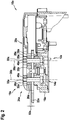
- FIG. 2 shows a section through the chainsaw 10a in the area of the fastening device 12a in the fastened state of the fastening unit 18a.
- the cutting plane of the section extends parallel to the fastening axes 38a.
- the fastening elements 28a rest in a direction that is at least substantially perpendicular to the fastening axes 38a on the cover element 30a of the cover unit 20a and / or the frictional connection elements 26a of the securing unit 24a.
- the fastening elements 28a are arranged along the fastening axes 38a separately from the securing unit 24a, in particular the frictional connection elements 26a.
- the two fastening elements 28a and the two counter-fastening elements 46a each have a thread 33a, the threads 33a of the fastening elements 28a in particular being designed to correspond to the threads 33a of the counter-fastening elements 46a.
- the frictional connection elements 26a are embedded in the cover unit 20a, in particular the cover element 30a, and fixed in recesses 32a of the cover element 30a by means of a force-fit and / or form-fit connection. It is also conceivable that the frictional connection elements 26a are formed in one piece with the cover element 30a by means of a material connection.
- the frictional connection elements 26a are arranged, in particular in the fastened state of the fastening unit 18a, on at least one side of the cover element 30a facing away from the fastening elements 28a.
- the cover element 30a is, in particular in the fastened state of the fastening unit 18a, at least partially arranged between the fastening elements 28a and the frictional connection elements 26a.
- the recesses 32a are designed to correspond to the basic shape of the force-locking elements 26a.
- the frictional connection elements 26a surround the fastening elements 28a at least substantially completely in a state of the fastening elements 28a arranged on the cover unit 20a, in particular the cover element 30a of the cover unit 20a, in particular in a plane extending at least substantially perpendicular to the fastening axes 38a. It is conceivable that the frictional connection elements 26a, in particular in the fastened state of the fastening unit 18a and / or a secured state of the fastening element 28a, along at least an angular range of in particular more than 5 °, preferably more than 15 ° and particularly preferably more than 45 °, around which fastening elements 28a are arranged, in particular along a circumferential direction of fastening elements 28a.
- the securing unit 24a in particular the frictional connection elements 26a, and / or the cover unit 20a, in particular the cover element 30a, are / is preferably provided to keep the fastening elements 28a at a distance from the chainsaw blade 22a when the fastening unit 18a is fastened. In the fastened state, the fastening elements 28a are at a distance 52a from the chainsaw blade 22a.
- the fastening elements 28a comprise a frictional connection region 34a and a fastening region 36a, a length 40a of the frictional connection region 34a along one of the fastening axes 38a of the fastening unit 18a being greater than a length 42a of the fastening region 36a.
- the frictional connection area 34a and the fastening area 36a are arranged one behind the other as viewed along one of the fastening axes 38a.
- the fastening elements 28a are designed such that a ratio between the length 42a of the fastening region 36a and the length 40a of the frictional connection region 34a along one of the fastening axes 38a is in particular at least 1.05, preferably at least 1.1 and particularly preferably 1.2.
- the threads 33a of the fastening elements 28a are arranged in the fastening region 36a. In the fastened state, the fastening elements 28a bear against the force-locking elements 26a within the frictional connection region 34a.
- the fastening elements 28a are designed in the frictional connection region 34a along one of the fastening axes 38a to be thread-free or free of connecting means.
- the fastening elements 28a have a total length along one of the fastening axes 38a, which in particular is equal to a sum of the length 40a of the frictional connection region 34a and the length 42a of the fastening region 36a.
- the fastening elements 28a have an at least substantially hollow ring-shaped basic shape in the frictional connection region 34a.
- the fastening elements 28a In the fastening region 36a, the fastening elements 28a have an at least essentially n-angular basic shape, which is designed in particular to correspond to a socket wrench.
- the fastening elements 28a face one another in the fastening region 36a at least substantially perpendicular to the plane extending perpendicular to the fastening axes 38a has a larger maximum diameter than in the frictional connection region 34a, in particular in a plane extending parallel thereto at least substantially perpendicular to the fastening axes 38a.
- the fastening elements 28a have a maximum inside diameter of the thread 33a in a plane extending at least substantially perpendicular to the fastening axes 38a, which is equal to, in particular smaller than, an inside diameter of the fastening elements 28a within the frictional connection area 34a.
- the sum of the total length of the fastening element 28a along one of the fastening axes 38a and a thickness 48a of the chainsaw sword 22a is less than a thread-free or connecting means-free length 50a of the counter-fastening elements 46a, which is arranged outside the drive unit 14a and the housing 16a.
- the frictional connection elements 26a are designed such that the fastening elements 28a are at least partially subjected to a securing force in at least one unsecured state of the fastening unit 18a.
- the fastening elements 28a are arranged, viewed along one of the fastening axes 38a, at least partially over the length 42a of the frictional connection region 34a on one of the frictional connection elements 26a. It is conceivable that the securing unit 24a has a further force-locking element 56a, which is in the Figure 3 is shown indicated by dashed lines.
- the further frictional connection element 56a is provided, in particular in at least one unsecured state of the fastening unit 18a, in particular by a frictional magnetic connection with at least one further fastening element 58a of the fastening unit 18a, which is arranged on the drive unit 14a and / or the housing 16a, the chainsaw sword 22a independently of the To fix and / or hold the cover unit 20a in at least one direction, in particular along one of the fastening axes 38a, on the drive unit 14a and / or the housing 16a.
- the further fastening element 58a is in particular in the Figure 3 indicated.
- the further fastening element 58a is formed in one piece with the drive unit 14a and / or the housing 16a.
- the further frictional connection element 56a is formed in one piece with the chain saw blade 22a.
- the further frictional connection element 56a is at least partially formed from a magnetizable material and / or as a magnet.
- the further frictional connection element 56a exerts a magnetic force on the further fastening element 58a, which is made of a magnetizable material and / or designed as a magnet, whereby in particular the chainsaw blade 22a can be fixed and / or held on the drive unit 14a and / or the housing 16a.
- the further frictional connection element 56a and the further fastening element 58a are designed in such a way that a magnetic force of the frictional connection between the further frictional connection element 56a and the further fastening element 58a is at least substantially greater than the summed weight forces of the chainsaw sword 22a, the cutting chain and the further frictional connection element 56a.
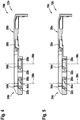
- the Figure 4 shows a section through a cover element 30b of a cover unit 20b and a securing unit 24b of an alternative embodiment of a fastening device 12b for fastening a chainsaw sword 22b to a drive unit 14b and / or a housing 16b of a chainsaw 10b, which in FIG Figure 4 however are not shown.
- the ones in the Figure 4 The fastening device 12b shown has an at least substantially analogous configuration to that in the description of FIG Figures 1 to 3 described fastening device 12a, so that with respect to an embodiment of the Figure 4 fastening device 12b shown at least essentially to the description of Figures 1 to 3 can be referenced.
- the fastening device 12a described has the in Figure 4 illustrated securing unit 24b of the fastening device 12b, preferably two force-locking elements 26b to one, in particular at least substantially form-fitting, non-positive connection with at least one fastening element 28b of a fastening unit 18b of the fastening device 12b, which is shown in FIG Figure 4 however are not shown.
- the securing unit 24b is designed as a force-locking unit, in particular at least essentially free of form-locking.
- the frictional connection elements 26b are at least partially toroidal on a side facing the fastening elements 28b.
- the frictional connection elements 26b are formed at least partially from a rubber and / or a plastic in a frictional connection region 44b of the frictional connection elements 26b.
- the surfaces 54b of the frictional connection elements 26b arranged in the frictional connection region 44b are designed to be curved.
- the frictional connection elements 26b are provided to secure the fastening elements 28b on the cover unit 20b, in particular the cover element 30b, by means of a frictional force.
- the frictional connection elements 26b are preferably provided to apply a frictional force to the fastening elements 28b in a direction that is at least substantially parallel to one of the fastening axes 38b when the frictional connection elements 26b lie within a frictional connection area of the frictional connection element 26b on the fastening elements 28b.
- the Figure 5 shows a section through a cover element 30c of a cover unit 20c and a securing unit 24c of an alternative embodiment of a fastening device 12c for fastening a chainsaw sword 22c to a drive unit 14c and / or a housing 16c of a chainsaw 10c, which in FIG Figure 5 however are not shown.
- the ones in the Figure 5 The fastening device 12c shown has an at least substantially analogous configuration to that in the description of FIG Figures 1 to 3 described fastening device 12a, so that with respect to an embodiment of the Figure 5 illustrated fastening device 12c at least essentially to the description of Figures 1 to 3 can be referenced.
- the fastening device 12a described has the in Figure 5
- the illustrated securing unit 24c of the fastening device 12c preferably two frictional locking elements 26c for a, in particular at least substantially form-locking-free, frictional connection with at least one fastening element 28c of a fastening unit 18c of the fastening device 12c, which is shown in FIG Figure 5 however are not shown.
- the Securing unit 24c is designed as a force-locking unit, in particular at least essentially free of form-locking.
- the frictional connection elements 26c are at least substantially conical on a side facing the fastening elements 28c.
- the frictional connection elements 26c are formed at least partially from a rubber and / or a plastic in a frictional connection region 44c of the frictional connection elements 26c.
- the surfaces 54c of the frictional connection elements 26c arranged in the frictional connection region 44c are flat, the fastening elements 28c tapering over the surfaces 54c in a direction that is at least substantially parallel to the fastening axes 38c and facing the chainsaw blade 22c.
- the frictional connection elements 26c are provided to secure the fastening elements 28c on the cover unit 20c, in particular the cover element 30c, by means of a frictional force.
- the frictional connection elements 26c are preferably provided to apply a frictional force to the fastening elements 28c in a direction that is at least substantially parallel to one of the fastening axes 38c when the frictional connection elements 26c lie within a frictional connection area of the frictional connection element 26c on the fastening elements 28c.
Landscapes
- Engineering & Computer Science (AREA)
- Mechanical Engineering (AREA)
- Life Sciences & Earth Sciences (AREA)
- Wood Science & Technology (AREA)
- Forests & Forestry (AREA)
- Sawing (AREA)
- Devices For Conveying Motion By Means Of Endless Flexible Members (AREA)
Applications Claiming Priority (1)
| Application Number | Priority Date | Filing Date | Title |
|---|---|---|---|
| DE102019206767.0A DE102019206767A1 (de) | 2019-05-10 | 2019-05-10 | Befestigungsvorrichtung zum Befestigen eines Kettensägenschwerts |
Publications (2)
| Publication Number | Publication Date |
|---|---|
| EP3736093A1 true EP3736093A1 (fr) | 2020-11-11 |
| EP3736093B1 EP3736093B1 (fr) | 2022-03-30 |
Family
ID=70483037
Family Applications (1)
| Application Number | Title | Priority Date | Filing Date |
|---|---|---|---|
| EP20172378.0A Active EP3736093B1 (fr) | 2019-05-10 | 2020-04-30 | Dispositif de fixation permettant de fixer un guide de tronçonneuse |
Country Status (3)
| Country | Link |
|---|---|
| EP (1) | EP3736093B1 (fr) |
| CN (1) | CN111958045B (fr) |
| DE (1) | DE102019206767A1 (fr) |
Citations (5)
| Publication number | Priority date | Publication date | Assignee | Title |
|---|---|---|---|---|
| WO2010005485A1 (fr) * | 2008-06-24 | 2010-01-14 | Mtd Products Inc | Tension de chaîne à couple limité pour outils électriques |
| WO2010105809A1 (fr) * | 2009-03-18 | 2010-09-23 | Gardena Manufacturing Gmbh | Dispositif de tension rapide pour une scie à chaîne et ensemble chaîne pour ce dernier |
| EP2777901A1 (fr) | 2007-10-12 | 2014-09-17 | Husqvarna AB | Dispositif de fixation pour outils électro-portatifs |
| US20180281225A1 (en) * | 2017-04-04 | 2018-10-04 | Andreas Stihl Ag & Co. Kg | Chainsaw |
| DE102017216870A1 (de) * | 2017-09-25 | 2019-03-28 | Robert Bosch Gmbh | Kettensägensystem |
Family Cites Families (2)
| Publication number | Priority date | Publication date | Assignee | Title |
|---|---|---|---|---|
| DE4142751C1 (en) * | 1991-12-23 | 1992-12-17 | Fa. Andreas Stihl, 7050 Waiblingen, De | Motor-driven chain-saw - has guide-plate with rear end held in place by fitting into shoulders on motor housing |
| DE202005013556U1 (de) * | 2005-08-27 | 2007-01-11 | Andreas Stihl Ag & Co. Kg | Arbeitsgerät |
-
2019
- 2019-05-10 DE DE102019206767.0A patent/DE102019206767A1/de active Pending
-
2020
- 2020-04-30 EP EP20172378.0A patent/EP3736093B1/fr active Active
- 2020-05-11 CN CN202010392774.9A patent/CN111958045B/zh active Active
Patent Citations (5)
| Publication number | Priority date | Publication date | Assignee | Title |
|---|---|---|---|---|
| EP2777901A1 (fr) | 2007-10-12 | 2014-09-17 | Husqvarna AB | Dispositif de fixation pour outils électro-portatifs |
| WO2010005485A1 (fr) * | 2008-06-24 | 2010-01-14 | Mtd Products Inc | Tension de chaîne à couple limité pour outils électriques |
| WO2010105809A1 (fr) * | 2009-03-18 | 2010-09-23 | Gardena Manufacturing Gmbh | Dispositif de tension rapide pour une scie à chaîne et ensemble chaîne pour ce dernier |
| US20180281225A1 (en) * | 2017-04-04 | 2018-10-04 | Andreas Stihl Ag & Co. Kg | Chainsaw |
| DE102017216870A1 (de) * | 2017-09-25 | 2019-03-28 | Robert Bosch Gmbh | Kettensägensystem |
Also Published As
| Publication number | Publication date |
|---|---|
| CN111958045B (zh) | 2024-07-09 |
| DE102019206767A1 (de) | 2020-11-12 |
| CN111958045A (zh) | 2020-11-20 |
| EP3736093B1 (fr) | 2022-03-30 |
Similar Documents
| Publication | Publication Date | Title |
|---|---|---|
| DE202009001440U1 (de) | Kraftgetriebenes Handwerkzeug mit Spanneinrichtung für ein Werkzeug | |
| EP2163358A1 (fr) | Poignée supplémentaire pour une machine-outil manuelle | |
| EP1332023A1 (fr) | Machine-outil a main comportant au moins une poignee | |
| DE102012222617A1 (de) | Welle zur Drehkopplung einer Hauptvorrichtung mit einer rohrförmigen Vorrichtung | |
| DE20309329U1 (de) | Befestigungsvorrichtung für Werkzeug | |
| DE102008000158A1 (de) | Handgriff für ein insbesondere motorisch angetriebenes Werkzeug | |
| DE1491029A1 (de) | Zahnaertzliches Handstueck | |
| EP3736093B1 (fr) | Dispositif de fixation permettant de fixer un guide de tronçonneuse | |
| EP2641700A1 (fr) | Adaptateur destiné à relier une poignée supplémentaire à une machine-outil manuelle | |
| EP3213879A1 (fr) | Poignee supplementaire reduisant les vibrations | |
| DE102007007636B3 (de) | Abzieher | |
| DE102014225916B4 (de) | Schlüssel mit konischer Fläche | |
| DE2116818C3 (de) | Schraubenzieher | |
| DE202007003334U1 (de) | Kupplungsvorrichtung zum Ein- und Ausdrehen von Schraubgliedern | |
| DE202015106961U1 (de) | Werkzeug | |
| DE102023118410B3 (de) | Sicherungsring für Schraubgerät, Reaktionskraftübertragungselement für Schraubgerät sowie Schraubgerät | |
| DE102011009722A1 (de) | Adapterelement für einen Schraubenschlüssel | |
| EP2067557B1 (fr) | Scie pouvant être entraînée de manière motorisée dotée d'une fixation de lame de scie et une lame de scie échangeable, ainsi que lame de scie | |
| DE29912871U1 (de) | Verschraubungswerkzeug mit formschlüssigem Adapter | |
| DE202005005708U1 (de) | Werkzeug zum Abziehen eines Wellendichtringes | |
| EP1121984B1 (fr) | Centrifugeuse avec collier de serrage comme moyen de montage | |
| DE466980C (de) | Abnehmbare Radnabe | |
| CH721132B1 (de) | Fräswerkzeug zum Planfräsen der Stirnfläche eines Rohrendes | |
| DE2404060C3 (de) | Sicherungselement aus Nichtmetall zwischen Gewindebolzen und Spannmutter | |
| DE102023201571A1 (de) | Schraubwerkzeug |
Legal Events
| Date | Code | Title | Description |
|---|---|---|---|
| PUAI | Public reference made under article 153(3) epc to a published international application that has entered the european phase |
Free format text: ORIGINAL CODE: 0009012 |
|
| STAA | Information on the status of an ep patent application or granted ep patent |
Free format text: STATUS: THE APPLICATION HAS BEEN PUBLISHED |
|
| AK | Designated contracting states |
Kind code of ref document: A1 Designated state(s): AL AT BE BG CH CY CZ DE DK EE ES FI FR GB GR HR HU IE IS IT LI LT LU LV MC MK MT NL NO PL PT RO RS SE SI SK SM TR |
|
| AX | Request for extension of the european patent |
Extension state: BA ME |
|
| STAA | Information on the status of an ep patent application or granted ep patent |
Free format text: STATUS: REQUEST FOR EXAMINATION WAS MADE |
|
| 17P | Request for examination filed |
Effective date: 20210511 |
|
| RBV | Designated contracting states (corrected) |
Designated state(s): AL AT BE BG CH CY CZ DE DK EE ES FI FR GB GR HR HU IE IS IT LI LT LU LV MC MK MT NL NO PL PT RO RS SE SI SK SM TR |
|
| GRAP | Despatch of communication of intention to grant a patent |
Free format text: ORIGINAL CODE: EPIDOSNIGR1 |
|
| STAA | Information on the status of an ep patent application or granted ep patent |
Free format text: STATUS: GRANT OF PATENT IS INTENDED |
|
| INTG | Intention to grant announced |
Effective date: 20220118 |
|
| GRAS | Grant fee paid |
Free format text: ORIGINAL CODE: EPIDOSNIGR3 |
|
| GRAA | (expected) grant |
Free format text: ORIGINAL CODE: 0009210 |
|
| STAA | Information on the status of an ep patent application or granted ep patent |
Free format text: STATUS: THE PATENT HAS BEEN GRANTED |
|
| AK | Designated contracting states |
Kind code of ref document: B1 Designated state(s): AL AT BE BG CH CY CZ DE DK EE ES FI FR GB GR HR HU IE IS IT LI LT LU LV MC MK MT NL NO PL PT RO RS SE SI SK SM TR |
|
| REG | Reference to a national code |
Ref country code: GB Ref legal event code: FG4D Free format text: NOT ENGLISH |
|
| REG | Reference to a national code |
Ref country code: CH Ref legal event code: EP |
|
| REG | Reference to a national code |
Ref country code: AT Ref legal event code: REF Ref document number: 1478758 Country of ref document: AT Kind code of ref document: T Effective date: 20220415 |
|
| REG | Reference to a national code |
Ref country code: DE Ref legal event code: R096 Ref document number: 502020000856 Country of ref document: DE |
|
| REG | Reference to a national code |
Ref country code: IE Ref legal event code: FG4D Free format text: LANGUAGE OF EP DOCUMENT: GERMAN |
|
| REG | Reference to a national code |
Ref country code: LT Ref legal event code: MG9D |
|
| PG25 | Lapsed in a contracting state [announced via postgrant information from national office to epo] |
Ref country code: SE Free format text: LAPSE BECAUSE OF FAILURE TO SUBMIT A TRANSLATION OF THE DESCRIPTION OR TO PAY THE FEE WITHIN THE PRESCRIBED TIME-LIMIT Effective date: 20220330 Ref country code: RS Free format text: LAPSE BECAUSE OF FAILURE TO SUBMIT A TRANSLATION OF THE DESCRIPTION OR TO PAY THE FEE WITHIN THE PRESCRIBED TIME-LIMIT Effective date: 20220330 Ref country code: NO Free format text: LAPSE BECAUSE OF FAILURE TO SUBMIT A TRANSLATION OF THE DESCRIPTION OR TO PAY THE FEE WITHIN THE PRESCRIBED TIME-LIMIT Effective date: 20220630 Ref country code: LT Free format text: LAPSE BECAUSE OF FAILURE TO SUBMIT A TRANSLATION OF THE DESCRIPTION OR TO PAY THE FEE WITHIN THE PRESCRIBED TIME-LIMIT Effective date: 20220330 Ref country code: HR Free format text: LAPSE BECAUSE OF FAILURE TO SUBMIT A TRANSLATION OF THE DESCRIPTION OR TO PAY THE FEE WITHIN THE PRESCRIBED TIME-LIMIT Effective date: 20220330 Ref country code: BG Free format text: LAPSE BECAUSE OF FAILURE TO SUBMIT A TRANSLATION OF THE DESCRIPTION OR TO PAY THE FEE WITHIN THE PRESCRIBED TIME-LIMIT Effective date: 20220630 |
|
| REG | Reference to a national code |
Ref country code: NL Ref legal event code: MP Effective date: 20220330 |
|
| PG25 | Lapsed in a contracting state [announced via postgrant information from national office to epo] |
Ref country code: LV Free format text: LAPSE BECAUSE OF FAILURE TO SUBMIT A TRANSLATION OF THE DESCRIPTION OR TO PAY THE FEE WITHIN THE PRESCRIBED TIME-LIMIT Effective date: 20220330 Ref country code: GR Free format text: LAPSE BECAUSE OF FAILURE TO SUBMIT A TRANSLATION OF THE DESCRIPTION OR TO PAY THE FEE WITHIN THE PRESCRIBED TIME-LIMIT Effective date: 20220701 Ref country code: FI Free format text: LAPSE BECAUSE OF FAILURE TO SUBMIT A TRANSLATION OF THE DESCRIPTION OR TO PAY THE FEE WITHIN THE PRESCRIBED TIME-LIMIT Effective date: 20220330 |
|
| PG25 | Lapsed in a contracting state [announced via postgrant information from national office to epo] |
Ref country code: NL Free format text: LAPSE BECAUSE OF FAILURE TO SUBMIT A TRANSLATION OF THE DESCRIPTION OR TO PAY THE FEE WITHIN THE PRESCRIBED TIME-LIMIT Effective date: 20220330 |
|
| PG25 | Lapsed in a contracting state [announced via postgrant information from national office to epo] |
Ref country code: SM Free format text: LAPSE BECAUSE OF FAILURE TO SUBMIT A TRANSLATION OF THE DESCRIPTION OR TO PAY THE FEE WITHIN THE PRESCRIBED TIME-LIMIT Effective date: 20220330 Ref country code: SK Free format text: LAPSE BECAUSE OF FAILURE TO SUBMIT A TRANSLATION OF THE DESCRIPTION OR TO PAY THE FEE WITHIN THE PRESCRIBED TIME-LIMIT Effective date: 20220330 Ref country code: RO Free format text: LAPSE BECAUSE OF FAILURE TO SUBMIT A TRANSLATION OF THE DESCRIPTION OR TO PAY THE FEE WITHIN THE PRESCRIBED TIME-LIMIT Effective date: 20220330 Ref country code: PT Free format text: LAPSE BECAUSE OF FAILURE TO SUBMIT A TRANSLATION OF THE DESCRIPTION OR TO PAY THE FEE WITHIN THE PRESCRIBED TIME-LIMIT Effective date: 20220801 Ref country code: ES Free format text: LAPSE BECAUSE OF FAILURE TO SUBMIT A TRANSLATION OF THE DESCRIPTION OR TO PAY THE FEE WITHIN THE PRESCRIBED TIME-LIMIT Effective date: 20220330 Ref country code: EE Free format text: LAPSE BECAUSE OF FAILURE TO SUBMIT A TRANSLATION OF THE DESCRIPTION OR TO PAY THE FEE WITHIN THE PRESCRIBED TIME-LIMIT Effective date: 20220330 Ref country code: CZ Free format text: LAPSE BECAUSE OF FAILURE TO SUBMIT A TRANSLATION OF THE DESCRIPTION OR TO PAY THE FEE WITHIN THE PRESCRIBED TIME-LIMIT Effective date: 20220330 |
|
| PG25 | Lapsed in a contracting state [announced via postgrant information from national office to epo] |
Ref country code: PL Free format text: LAPSE BECAUSE OF FAILURE TO SUBMIT A TRANSLATION OF THE DESCRIPTION OR TO PAY THE FEE WITHIN THE PRESCRIBED TIME-LIMIT Effective date: 20220330 Ref country code: IS Free format text: LAPSE BECAUSE OF FAILURE TO SUBMIT A TRANSLATION OF THE DESCRIPTION OR TO PAY THE FEE WITHIN THE PRESCRIBED TIME-LIMIT Effective date: 20220730 Ref country code: AL Free format text: LAPSE BECAUSE OF FAILURE TO SUBMIT A TRANSLATION OF THE DESCRIPTION OR TO PAY THE FEE WITHIN THE PRESCRIBED TIME-LIMIT Effective date: 20220330 |
|
| REG | Reference to a national code |
Ref country code: DE Ref legal event code: R097 Ref document number: 502020000856 Country of ref document: DE |
|
| REG | Reference to a national code |
Ref country code: BE Ref legal event code: MM Effective date: 20220430 |
|
| PG25 | Lapsed in a contracting state [announced via postgrant information from national office to epo] |
Ref country code: MC Free format text: LAPSE BECAUSE OF FAILURE TO SUBMIT A TRANSLATION OF THE DESCRIPTION OR TO PAY THE FEE WITHIN THE PRESCRIBED TIME-LIMIT Effective date: 20220330 Ref country code: LU Free format text: LAPSE BECAUSE OF NON-PAYMENT OF DUE FEES Effective date: 20220430 Ref country code: DK Free format text: LAPSE BECAUSE OF FAILURE TO SUBMIT A TRANSLATION OF THE DESCRIPTION OR TO PAY THE FEE WITHIN THE PRESCRIBED TIME-LIMIT Effective date: 20220330 |
|
| PLBE | No opposition filed within time limit |
Free format text: ORIGINAL CODE: 0009261 |
|
| STAA | Information on the status of an ep patent application or granted ep patent |
Free format text: STATUS: NO OPPOSITION FILED WITHIN TIME LIMIT |
|
| PG25 | Lapsed in a contracting state [announced via postgrant information from national office to epo] |
Ref country code: BE Free format text: LAPSE BECAUSE OF NON-PAYMENT OF DUE FEES Effective date: 20220430 |
|
| 26N | No opposition filed |
Effective date: 20230103 |
|
| PG25 | Lapsed in a contracting state [announced via postgrant information from national office to epo] |
Ref country code: IE Free format text: LAPSE BECAUSE OF NON-PAYMENT OF DUE FEES Effective date: 20220430 |
|
| PG25 | Lapsed in a contracting state [announced via postgrant information from national office to epo] |
Ref country code: SI Free format text: LAPSE BECAUSE OF FAILURE TO SUBMIT A TRANSLATION OF THE DESCRIPTION OR TO PAY THE FEE WITHIN THE PRESCRIBED TIME-LIMIT Effective date: 20220330 |
|
| PG25 | Lapsed in a contracting state [announced via postgrant information from national office to epo] |
Ref country code: IT Free format text: LAPSE BECAUSE OF FAILURE TO SUBMIT A TRANSLATION OF THE DESCRIPTION OR TO PAY THE FEE WITHIN THE PRESCRIBED TIME-LIMIT Effective date: 20220330 |
|
| REG | Reference to a national code |
Ref country code: CH Ref legal event code: PL |
|
| PG25 | Lapsed in a contracting state [announced via postgrant information from national office to epo] |
Ref country code: LI Free format text: LAPSE BECAUSE OF NON-PAYMENT OF DUE FEES Effective date: 20230430 Ref country code: CH Free format text: LAPSE BECAUSE OF NON-PAYMENT OF DUE FEES Effective date: 20230430 |
|
| PG25 | Lapsed in a contracting state [announced via postgrant information from national office to epo] |
Ref country code: MK Free format text: LAPSE BECAUSE OF FAILURE TO SUBMIT A TRANSLATION OF THE DESCRIPTION OR TO PAY THE FEE WITHIN THE PRESCRIBED TIME-LIMIT Effective date: 20220330 Ref country code: CY Free format text: LAPSE BECAUSE OF FAILURE TO SUBMIT A TRANSLATION OF THE DESCRIPTION OR TO PAY THE FEE WITHIN THE PRESCRIBED TIME-LIMIT Effective date: 20220330 |
|
| PG25 | Lapsed in a contracting state [announced via postgrant information from national office to epo] |
Ref country code: HU Free format text: LAPSE BECAUSE OF FAILURE TO SUBMIT A TRANSLATION OF THE DESCRIPTION OR TO PAY THE FEE WITHIN THE PRESCRIBED TIME-LIMIT; INVALID AB INITIO Effective date: 20200430 |
|
| PG25 | Lapsed in a contracting state [announced via postgrant information from national office to epo] |
Ref country code: MT Free format text: LAPSE BECAUSE OF FAILURE TO SUBMIT A TRANSLATION OF THE DESCRIPTION OR TO PAY THE FEE WITHIN THE PRESCRIBED TIME-LIMIT Effective date: 20220330 |
|
| PGFP | Annual fee paid to national office [announced via postgrant information from national office to epo] |
Ref country code: DE Payment date: 20250624 Year of fee payment: 6 |
|
| PGFP | Annual fee paid to national office [announced via postgrant information from national office to epo] |
Ref country code: FR Payment date: 20250428 Year of fee payment: 6 |
|
| PGFP | Annual fee paid to national office [announced via postgrant information from national office to epo] |
Ref country code: AT Payment date: 20250721 Year of fee payment: 5 |
|
| PG25 | Lapsed in a contracting state [announced via postgrant information from national office to epo] |
Ref country code: TR Free format text: LAPSE BECAUSE OF FAILURE TO SUBMIT A TRANSLATION OF THE DESCRIPTION OR TO PAY THE FEE WITHIN THE PRESCRIBED TIME-LIMIT Effective date: 20220330 |
|
| PGFP | Annual fee paid to national office [announced via postgrant information from national office to epo] |
Ref country code: GB Payment date: 20260324 Year of fee payment: 7 |