EP3736189A1 - Verteiler und oleodynamisches bremssystem für landwirtschaftliches fahrzeug - Google Patents
Verteiler und oleodynamisches bremssystem für landwirtschaftliches fahrzeug Download PDFInfo
- Publication number
- EP3736189A1 EP3736189A1 EP20165716.0A EP20165716A EP3736189A1 EP 3736189 A1 EP3736189 A1 EP 3736189A1 EP 20165716 A EP20165716 A EP 20165716A EP 3736189 A1 EP3736189 A1 EP 3736189A1
- Authority
- EP
- European Patent Office
- Prior art keywords
- distributor
- chamber
- pressure
- oil
- seat
- Prior art date
- Legal status (The legal status is an assumption and is not a legal conclusion. Google has not performed a legal analysis and makes no representation as to the accuracy of the status listed.)
- Granted
Links
Images


Classifications
-
- B—PERFORMING OPERATIONS; TRANSPORTING
- B60—VEHICLES IN GENERAL
- B60T—VEHICLE BRAKE CONTROL SYSTEMS OR PARTS THEREOF; BRAKE CONTROL SYSTEMS OR PARTS THEREOF, IN GENERAL; ARRANGEMENT OF BRAKING ELEMENTS ON VEHICLES IN GENERAL; PORTABLE DEVICES FOR PREVENTING UNWANTED MOVEMENT OF VEHICLES; VEHICLE MODIFICATIONS TO FACILITATE COOLING OF BRAKES
- B60T15/00—Construction arrangement, or operation of valves incorporated in power brake systems and not covered by groups B60T11/00 or B60T13/00
- B60T15/02—Application and release valves
- B60T15/18—Triple or other relay valves which allow step-wise application or release and which are actuated by brake-pipe pressure variation to connect brake cylinders or equivalent to compressed air or vacuum source or atmosphere
- B60T15/181—Trailer control valves
Definitions
- the present invention relates to an oleodynamic braking distributor and system for an agricultural or forestry vehicle.
- the present invention finds advantageous application in an oleodynamic braking distributor and system which comply with the EU 167/2013 regulation which concerns the provisions relating to vehicle braking for the purposes of homologation of agricultural and forestry vehicles (hereinafter EU 167/2013 regulation) and relating to the braking of towed vehicles.
- the EU 167/2013 regulation requires, among other things, that an agricultural or forestry vehicle has a main line crossed by high-pressure oil and a secondary line crossed by low-pressure oil separated from each other so that a line can guarantee the braking of the towed vehicle also in case of malfunction of the other.
- the EU 167/2013 regulation also requires specific specifications relating to the braking timing and methods of the towed vehicle in the event of a breakdown.
- the EU 167/2013 regulation also provides for a transitional period, during which it is still possible to use towed vehicles that follow the regulations prior to 2016 or controlled by a single pressure line.
- Oleodynamic braking distributors for an agricultural or forestry vehicle for delivering fluid under pressure to towed vehicles are known, for example from EP0400432 A1 , however these types of distributors are controlled by a single line under pressure.
- Oleodynamic braking distributors for an agricultural or forestry vehicle for delivering fluid under pressure to towed vehicles are known, for example from EP3202629 A1 , however these types of distributors do not allow remote control.
- the object of the present invention is to provide an oleodynamic braking distributor and system for an agricultural or forestry vehicle which comply with the requirements of the EU 167/2013 regulation.
- the object of the present invention is to provide an oleodynamic braking distributor and system which comprise a main line and a secondary line separate from each other (according to the provisions of the EU 167/2013 regulation) and an automatic system for operating an emergency braking system in case of fault detection on a line.
- the object of the present invention is to provide an oleodynamic braking distributor and system which can also be used for towed vehicles made according to the regulations prior to 2016, which provides only one pressure line for towed vehicles.
- the object of the present invention is to provide an oleodynamic braking distributor and system which can be used independently on board towed vehicles made both according to the EU 167/2013 regulation and according to the previous regulation.
- the object of the present invention is to provide an improved oleodynamic distributor and system.
- a brake valve, an oleodynamic braking distributor and system are provided according to what is mentioned in the appended claims.
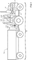
- reference VI shows an agricultural or forestry vehicle for braking a towed vehicle VII coupled to the agricultural or forestry vehicle VI.
- a distributor D is a component of an oleodynamic braking system 1 (illustrated schematically in Figure 5 ) of the vehicle VI.
- the vehicle VI has a control delivery Y of oil under pressure of the braking system of the vehicle VI.
- the control delivery Y is regulated by the brake pedal of the agricultural or forestry vehicle VI.
- the system 1 comprises, in a known manner, a main high-pressure oil delivery PI, an additional low-pressure oil delivery PII and a discharge T.
- the main delivery PI is configured to supply oil at a pressure up to about 150 bar to a main line LI.
- the additional delivery PII is configured to supply oil at a pressure up to about 30 bar to an additional line LII.
- I and II identify the elements connected to the main line LI and to the additional line LII, respectively, below and in the Figures.
- the system 1 comprises, in a known manner, attachments 2 configured to hydraulically connect, in use, to respective joints 3 of a towed vehicle VII.
- attachments 2 configured to hydraulically connect, in use, to respective joints 3 of a towed vehicle VII.
- both attachments 2 of the distributor D will be connected to the respective joints 3.
- the distributor D is installed in any position of the agricultural vehicle VI, even distant from the attachments 2, which are generally located in a rear position of the vehicle VI.
- the distributor D is connected remotely, i.e. remote.
- the system 1 is provided with lines 41, 411, each connecting a respective attachment 21, 211 with the distributor D.
- the distributor D is placed at the rear in the vicinity of the attachments 2.
- the attachments 2 are advantageously connected directly mechanically with the distributor D.
- the system 1 comprises a presence detector 5, which is configured to determine how many joints 3 are connected to the system 1.
- the presence detector 5 determines whether the towed vehicle VII has one line or two lines of oil under pressure.
- the presence detector 5 can be selected from a group of presence detectors 5 which are different from each other by type.
- the presence detector 5 can be: electric, mechanical, hydraulic, pneumatic, magnetic, electromagnetic, and the like.
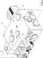
- the distributor D comprises a body 6 inside which chambers and lines are formed for housing valves and, respectively, for the passage of oil.
- the distributor D comprises:
- the distributor D furthermore comprises a selection valve 8 which is configured to operate the drive cartridge 711, according to the type of towed vehicle VII coupled to the vehicle VI.
- the selection valve 8 can be operated in any way: electrically, pneumatically, hydraulically, mechanically, magnetically, and the like.
- the selection valve 8 is a solenoid valve and is operated remotely, in particular the presence detector 5 emits a signal which is used, directly or through a control unit (not shown), to operate the selection valve 8 itself.
- the drive cartridge 711 is a slide valve.
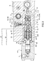
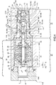
- the drive cartridge 711 is formed inside a main dispensing chamber 9 of the distributor D.
- the main dispensing chamber 9 has a longitudinal axis A.
- the main dispensing chamber 9 has a main dispensing inlet 10 for high-pressure oil, fed by the main delivery PI, and a main dispensing outlet 11 for delivering, in a known manner, high-pressure oil to the towed vehicle VII connected to the agricultural or forestry vehicle VI.
- the main dispensing outlet 11 connects the main dispensing chamber 9 with the discharge T.
- the drive cartridge 711 also comprises a dispensing seat 12. It should be noted that the term seat refers to a cylindrical body configured to implement specific hydraulic connections inside a respective chamber.
- the dispensing seat 12 is coaxial to the longitudinal axis A.
- the dispensing seat 12 has a central through cavity 13 which crosses longitudinally, and in its entirety, the dispensing seat 12 itself.
- the dispensing seat 12 can be solid, i.e. not have the central cavity 13, and manage the directing of the oil by other means, for example outer shapes or transverse holes.
- the main dispensing chamber 9 has a plurality of chambers 14, i.e. areas in fluid communication with the outside. Each chamber 14 is substantially delimited by an annular groove 114 made on the outside of the dispensing seat 12.
- the chambers 14 of the dispensing seat 12 are hereinafter identified as signal chamber 14A, selection chamber 14B and discharge chamber 14C.
- the chambers 14 are distributed axially along the dispensing seat 12.
- the selection chamber 14B is axially interposed between the signal chamber 14A and the discharge chamber 14C.
- the dispensing seat 12 has at least one radial channel 15 for each chamber 14. Each radial channel 15 puts in fluid communication the central cavity 13 with a respective inner chamber 16.
- the channels are identified with letters A, B and C according to the chamber 14 with which they are in communication.
- Each inner chamber 16 is substantially by an annular groove 116 made inside the dispensing seat 12.
- the dispensing seat 12 is interposed between the main delivery inlet 10 for high-pressure oil and the main delivery outlet 11.
- the oil in order to flow from the main delivery inlet 10 to the main delivery outlet 11 passes through the dispensing seat 12.
- the oil passes through the inner chamber 16C, the radial channel 15C and the discharge chamber 14C of the dispensing seat 12 to pass from the main delivery inlet 10 to the main delivery outlet 11.
- the signal chamber 14A is in fluid communication with a parking oil line LIII.
- the signal chamber 14A is in communication with an oil inlet 210 at a parking pressure.
- the drive cartridge 711 is configured to put the oil coming from the parking inlet 210 in communication with a secondary delivery outlet 111, when the pressure of the oil coming from the main delivery PI is below a predefined value.
- the secondary delivery outlet 111 is in communication with the discharge T.
- the selection valve 8 is configured to selectively connect the selection chamber 14B with the discharge T or with the main line LI.
- the selection valve 8 is part of a switching system 17, which comprises a passage channel 18 which connects the selection chamber 14B with the selection valve 8 and a drive line 19 which connects the passage channel 18 with the control line CL.
- a calibrated orifice 20 is made along the drive line 19, which allows the oil to leak from the main line LI to the passage channel 18.
- the selection valve 8 selectively opens and closes the passage channel 18.
- the drive line 19 is in fluid communication with the passage channel 18 in an intermediate position between the selection chamber 14B and the selection valve 8.
- the passage channel 18 is connected to the discharge T and, consequently, the selection chamber 14B is also connected to the discharge T. Furthermore, the oil which leaks from the drive line 19 is in turn directed to the discharge T.
- the selection valve 8 When the selection valve 8 is closed, the oil which leaks from the drive line 19 fills the passage channel 18 and the selection chamber 14B. Therefore, the selection chamber 14B is brought to the same pressure as the control line CL.
- the drive cartridge 711 comprises a pin 21 which is slidably mounted axially inside the central cavity 13 of the dispensing seat 12.
- a clearance can be provided between the pin 21 and the main dispensing seat 12, so as to allow a leakage of oil from the main line LI to the selection chamber 14B.
- the selection chamber 14B can be connected to the discharge T by means of the selection valve 8.
- the signal chamber 14A is in communication with a parking oil line LIII, as will be better illustrated below (it is noted that a towed vehicle VII according to the EU 167/2013 regulation comprises a parking braking system, of a known type and not shown, which is configured to block the wheels of the towed vehicle VII when it is not supplied with pressurized oil).
- the drive cartridge 711 also integrates the self-diagnosis and emergency braking system, as will be better illustrated below.
- the pin 21 has an inner cavity 22.
- the pin 21 comprises a calibrated dowel 23 which has a passage hole 50 and allows the oil to leak from the main inlet 10 into the inner cavity 22.
- the calibrated dowel 23 is applied to an axial end of the pin 21.
- the calibrated dowel 23 faces the main delivery inlet 10.
- the pin 21 has a double diameter.
- the pin 21 comprises a smaller shutter 24 having an outer diameter d1 and a larger shutter 25 having an outer diameter d2, wherein d1 ⁇ d2.
- the larger shutter 25 projects radially outside the smaller shutter 24.
- the pin 21 has an outer thrust surface 26 substantially perpendicular to the axis A.
- the outer thrust surface 26 is shaped as a circular crown and is at the passage between the smaller shutter 24 and the larger shutter 25.
- the smaller shutter 24 is axially interposed between the larger shutter 25 and the main delivery inlet 10.
- the calibrated dowel 23 is applied to a free end of the smaller shutter 24.
- the calibrated dowel 23 has an axial thrust surface 27 facing the main delivery inlet 10.
- the pin 21 is inserted into the main dispensing seat 12, so that the outer thrust surface 26 faces the inner selection chamber 16B.
- the total thrust R which develops on the pin 21 changes, in use, according to whether the selection chamber 14B is connected to the control line CL or to the discharge T.
- the pin 21 also has a radial hole 28 which connects the inner cavity 22 of the pin 21 with the outside.
- the radial hole 28 faces the outside of the pin 21 along the larger shutter 25 and is in communication with the inner signal chamber 16A.
- the pin 21 can have a plurality of radial holes 28 uniformly distributed radially around the axis A and at the same axial sector of the pin 21.
- each radial hole 28 puts the oil inlet 210 at the parking pressure in communication with the inner cavity 22.
- the oil inlet 210 at the parking pressure is in fluid connection with the secondary delivery outlet 111 through the inner cavity 22.
- the drive cartridge 7II further comprises a slider 29 which is mounted axially sliding inside the inner cavity 22 of the pin 21.
- the slider 29 is movable from a closed position C (indicated with a dotted line in Figures 3 and 4 ) to an open position O (indicated with a dotted line in Figures 3 and 4 ).
- the slider 29 has an outer groove 30.
- the outer groove 30 is configured to put the parking line LIII in communication with the discharge T when the slider 29 is in the open position O.
- the outer groove 30 is configured to put the signal chamber 14A in communication with the secondary delivery outlet 111 when it is arranged in the open position O.
- the outer groove 30 is annular. According to the variants not shown, the outer groove 30 can have different shapes and/or dimensions.
- the slider 29 has a head 31 and a stem 32, the outer groove 30 is interposed between the head 31 and the stem 32.
- the head 31 faces the inside of the inner cavity 22.
- the inner cavity 22 feels the pressure of the oil leaked through the calibrated dowel 23.
- the oil under pressure in the inner cavity 22 exerts a closing thrust Fc on the head 31 of the slider 29, i.e. a force that pushes the slider 29 towards the closed position C.
- the stem 32 of the slider 29 is connected to an opening assembly 33 which exerts an opening thrust Fa on the stem 32 of the slider 29, i.e. a force that pushes the slider 29 towards the open position O.
- the closing thrust Fc and the opening thrust Fa are opposite to each other.
- the total thrust force R is the result obtained from the opening thrust Fa and the closing thrust Fc.
- the slider 29 is configured to slide axially in one direction v1, or in the opposite direction v2, according to the direction of the total thrust force R.
- the emergency opening assembly 33 is configured to move the slider 29 to the open position O in the event that the closing thrust Fc exerted on the head 31 does not exceed a minimum threshold value.
- this situation is indicative of a pressure loss (therefore of a failure) along the control line CL.
- the emergency opening assembly 33 comprises a helical spring 34 fitted around the stem 32 of the slider 29, a shoulder 35 for a first end of the spring 34 and a plate 36 connected to the slider 29 and which acts as an abutment element for a second end of the spring 34.
- the spring 34 is preloaded and is calibrated so as to exert a predefined opening thrust Fa on the slider 29.
- the drive cartridge 7II further comprises a calibration assembly 37 configured to vary the working pressure of the brake in proportion to the control received from the control delivery Y.
- the braking force of the drive cartridge 711 must be related to the mass of the towed vehicle VII. Furthermore, the braking force of the drive cartridge 711 must be related to the presence on the towed vehicle VII of one or two oil lines.
- the calibration assembly 37 is regulated by the pin 21.
- the pin 21 is configured to exert a variable calibration thrust Ft according to whether the distributor D is connected to a towed vehicle VII having one or two oil lines, as schematically shown in Figures 7 and 8 .
- the oil under pressure inside the main line LI exerts a basic calibration thrust Ft1, i.e. a force that pushes the pin 21, proportional to the axial thrust surface 27 of the calibrated dowel 23.
- the selection valve 8 is open and the selection chamber 14B of the dispensing seat 12 is connected to the discharge T.
- the oil coming from the main line LI exerts a calibration thrust Ft which corresponds to the basic calibration thrust Ft1 exerted on the calibrated dowel 23 of the pin 21.
- the selection valve 8 is closed and the selection chamber 14B receives oil under pressure from the drive line 19. Therefore, inside the selection chamber 14B the oil is at a pressure equal to that of the main line LI.
- the oil under pressure inside the selection chamber 14B fills the respective inner selection chamber 16B through one or more radial channels 15.
- the oil under pressure inside the inner selection chamber 16B exerts an auxiliary thrust Ft2 on the outer thrust surface 26 of the pin 21.
- the calibration thrust Ft corresponds to the sum of the basic calibration thrust Ft1 and the auxiliary thrust Ft2.
- Ft Ft 1 ⁇ + Ft 2 ⁇
- the calibration assembly 37 is configured to act axially on the pin 21 and is configured to make the braking action proportional with respect to the pressure on the control line CL. In other words, the calibration assembly 37 keeps the pin 21 in a predefined working position along the longitudinal axis A, maintaining the balance between the calibration thrust and the thrust of the calibration assembly 37 itself.
- the drive cartridge 711 further comprises a braking piston 38A on which the axial thrust of the drive assembly 110 acts.
- the braking piston 38A is part of the calibration assembly 37.
- the calibration assembly 37 further comprises a shoulder element 38B and elastic return means 39 interposed between the braking piston 38A and the shoulder element 38B.
- the braking piston 38A and the shoulder element 38B are housed inside the main dispensing chamber 9 and are axially movable along said main dispensing chamber 9.
- the shoulder element 38B is axially interposed between the braking piston 38A and the main dispensing seat 12.
- the braking piston 38A is an axial-symmetric body and substantially has the shape of a cup body.
- the braking piston 38A has a through hole 40 inside which the stem 32 of the slider 29 is inserted.
- the shoulder element 38B rests on the pin 21 and is translated along the axis A according to the balance of forces generated by each single braking.
- the shoulder element 38B has an axial-symmetric body with a central hole 41.
- the slider 29 is mounted movable through the central hole 41.
- the elastic return means 39 are springs.
- the calibration assembly 37 comprises two helical springs 42.
- the helical springs 42 are fitted around the slider 29.
- the helical springs 42 have outer diameters different from each other, so that one can be mounted inside the other and are coaxial with each other.
- the helical spring 34 of the emergency opening assembly 33 is at one end against the braking piston 38A of the calibration assembly 37.
- the spring 34 of the emergency opening assembly 33 is coaxial with the springs 42 of the calibration assembly 37 and has a diameter such as to be able to be placed inside the other springs 42.
- the calibration assembly 37 comprises three coaxial springs 42 mounted one inside the other.
- the innermost spring 34 is the spring 34 of the emergency opening assembly 33 and pushes the slider 29.
- the two outermost springs 42 are of the calibration assembly 37 and push the shoulder element 38B.
- the main dispensing chamber 9 has a shaft stop ring 43 configured to axially constrain the seat 12.
- the ring 43 divides the main dispensing chamber 9 into a control chamber 44 and a drive chamber 45.
- the drive chamber 45 is in communication with the main line LI and houses the dispensing seat 12, as described above.
- the drive chamber 44 houses the calibration assembly 37 and is in communication with the drive assembly 110.
- the drive assembly 110 is of the hydraulic type, according to variants not shown, it can be selected from a group of drive assemblies different from each other by type.
- the drive assembly 110 may alternatively be mechanical, pneumatic, electronic, magnetic, electromagnetic, and the like.
- the selection valve 8 advantageously modifies the internal balance of the forces of the calibration cartridge 711.
- the EU 167/2013 regulation substantially changing the way in which the braking systems operate and also their construction (two lines under pressure instead of a single line under pressure), as a first consequence, causes a difference in the braking response behavior of towed vehicles.
- the switching system 17 of the type described above allows regulating the braking action of the distributor D itself according to whether it is connected to a towed vehicle VII according to the old or the EU 167/2013 regulation and contributes to ensuring braking compliance by the distributor D with both the old regulation and the EU 167/2013 regulation.
- the distributor D further comprises an emergency control 46 which can be operated directly by an operator, for example a handbrake.
- the distributor D is connected to a towed vehicle VII which can be built according to the old regulation or to the EU 167/2013 regulation.
- the operation of the distributor D will be described below according to the type of towed vehicle VII.
- an operator acting on the brake pedal, or on the control delivery Y, of the agricultural or forestry vehicle VI activates the drive assembly 110 by sliding the braking piston 38A into a braking position and, consequently, bringing the seat 12 in a working position L so as to close the connection with the discharge T. Therefore, the oil pressure in the control line CL as well as in the drive cartridge 7II increases.
- the drive cartridge 711 moves to a delivery position, in which high pressure oil is sent to the towed vehicle VII.
- the low pressure oil is fed by the additional delivery PII and is conveyed to the towed vehicle VII.
- a towed vehicle VII according to the EU 167/2013 regulation comprises a parking braking system (of a known type and not shown) which is configured to block the wheels of the towed vehicle VII when it is not connected to an agricultural or forestry vehicle VI.
- the parking braking system is configured to block the wheels of the towed vehicle VII when it is not supplied with pressurized oil.
- the selection valve 8 allows modifying the braking features to adapt the behavior of the distributor D to the regulation prior to EU 167/2013.
- the aim is to ensure that the towed vehicle VII anticipates braking with respect to the agricultural or forestry vehicle VI.
- the main dispensing seat 12 can be replaced with another one of different dimensions (in particular with a different outer thrust surface 26 or different axial thrust surface 27), so as to obtain the correct braking ratio required for agricultural or forestry vehicles VI of different specific weights.
- the towed vehicles VII according to the old regulation in addition to not providing an additional low-pressure oil line LII, require a minimum value of the oil pressure for the release of the parking braking system.
- a minimum value of the oil pressure for the release of the parking braking system.
- the low-pressure oil coming from the additional line LII is used to act on the parking braking system, so as to release the wheels of the towed vehicle VII. If the delivery of oil to the towed vehicle VII is interrupted, the parking braking system is activated, in a known manner, for braking the wheels of the towed vehicle VII.
- the distributor D has the advantage of guaranteeing, in the case of application to a vehicle built according to the old regulations, a minimum pre-established pressure for releasing the braking system.
- the distributor D allows the braking action of the towed vehicles VII to be re-modulated according to the old regulations as desired, according to the type of compensation seat installed.
- the distributor D also has the advantage of guaranteeing the activation of towed vehicles VII according to the EU 167/2013 regulation and of providing automatic braking in case of failure along the control line CL.
- the drive cartridge 711 of the distributor D has the advantage of having integrated therein the detection system of any anomalies.
- the drive cartridge 711 of the type described above has the advantage of being compact, with a consequent reduction in the overall dimensions of the distributor D.
- the drive cartridge 711 of the type described above has the advantage of being able to be regulated remotely, therefore, the distributor D can be remote-controlled, that is to say, positioned far from an attachment area with a towed vehicle VII.
- the drive cartridge 711 of the type described above has the advantage that it can be easily customized for the different types of towed vehicles VII, by modifying the extension of the outer thrust surface 26 and/or the axial thrust surface 27.
- the drive cartridge 7II has the advantage of being simpler and having fewer components than a main brake valve of a known type.
- the drive cartridge 7II has the advantage that the calibration takes place not by modifying the drive assembly 110 (as occurs in systems of the known type) but by modifying the thrust surface exposed to the main line LI.
- the distributor D and the system 1 of the type described above are particularly effective and versatile. Furthermore, they guarantee an economic advantage for the user who can install a distributor D on a towed vehicle VII, regardless of whether it is made according to the new or old regulations.
- the distributor D and the system 1 of the type described above are more compact and versatile than those of the known type.
Landscapes
- Engineering & Computer Science (AREA)
- Transportation (AREA)
- Mechanical Engineering (AREA)
- Valves And Accessory Devices For Braking Systems (AREA)
Applications Claiming Priority (1)
| Application Number | Priority Date | Filing Date | Title |
|---|---|---|---|
| IT201900004361 | 2019-03-26 |
Publications (2)
| Publication Number | Publication Date |
|---|---|
| EP3736189A1 true EP3736189A1 (de) | 2020-11-11 |
| EP3736189B1 EP3736189B1 (de) | 2021-09-15 |
Family
ID=67108003
Family Applications (1)
| Application Number | Title | Priority Date | Filing Date |
|---|---|---|---|
| EP20165716.0A Active EP3736189B1 (de) | 2019-03-26 | 2020-03-25 | Verteiler und oleodynamisches bremssystem für landwirtschaftliches fahrzeug |
Country Status (1)
| Country | Link |
|---|---|
| EP (1) | EP3736189B1 (de) |
Cited By (2)
| Publication number | Priority date | Publication date | Assignee | Title |
|---|---|---|---|---|
| CN112727825A (zh) * | 2020-12-23 | 2021-04-30 | 象山兴驰液压润滑有限公司 | 一种液压分配器的连接结构 |
| CN119527264A (zh) * | 2024-11-21 | 2025-02-28 | 浙江吉利控股集团有限公司 | 一种紧急制动装置、液压制动系统及车辆 |
Citations (6)
| Publication number | Priority date | Publication date | Assignee | Title |
|---|---|---|---|---|
| EP0400432A1 (de) | 1989-06-02 | 1990-12-05 | Atanasio Paganini | Gerät zum Herstellen einer hydraulischen Verbindung und zum Steuern zwischen einem Traktor-Arbeitskreis und dem Bremssystem eines Anhängers |
| WO1994010018A1 (en) * | 1992-10-30 | 1994-05-11 | Total Quality Enterprises, Inc. | Control valve for hydraulic braking system |
| EP3000672A1 (de) * | 2014-05-30 | 2016-03-30 | Studio Tecnico 6 M S.R.L. | Anhängerventilanordnung |
| EP3085590A1 (de) * | 2014-11-11 | 2016-10-26 | Studio Tecnico 6 M S.R.L. | Vorrichtung zur steuerung des bremssystems eines anhängerfahrzeugs |
| EP3202629A1 (de) | 2016-02-02 | 2017-08-09 | Slanzi Oleodinamica S.r.l. | Verteiler und hydraulische bremsanlage eines landwirtschaft- oder forstfahrzeugs |
| EP3243715A1 (de) * | 2016-05-11 | 2017-11-15 | Slanzi Oleodinamica S.r.l. | Hydraulischer verteiler zum bremsen eines geräteanhängers |
-
2020
- 2020-03-25 EP EP20165716.0A patent/EP3736189B1/de active Active
Patent Citations (6)
| Publication number | Priority date | Publication date | Assignee | Title |
|---|---|---|---|---|
| EP0400432A1 (de) | 1989-06-02 | 1990-12-05 | Atanasio Paganini | Gerät zum Herstellen einer hydraulischen Verbindung und zum Steuern zwischen einem Traktor-Arbeitskreis und dem Bremssystem eines Anhängers |
| WO1994010018A1 (en) * | 1992-10-30 | 1994-05-11 | Total Quality Enterprises, Inc. | Control valve for hydraulic braking system |
| EP3000672A1 (de) * | 2014-05-30 | 2016-03-30 | Studio Tecnico 6 M S.R.L. | Anhängerventilanordnung |
| EP3085590A1 (de) * | 2014-11-11 | 2016-10-26 | Studio Tecnico 6 M S.R.L. | Vorrichtung zur steuerung des bremssystems eines anhängerfahrzeugs |
| EP3202629A1 (de) | 2016-02-02 | 2017-08-09 | Slanzi Oleodinamica S.r.l. | Verteiler und hydraulische bremsanlage eines landwirtschaft- oder forstfahrzeugs |
| EP3243715A1 (de) * | 2016-05-11 | 2017-11-15 | Slanzi Oleodinamica S.r.l. | Hydraulischer verteiler zum bremsen eines geräteanhängers |
Cited By (2)
| Publication number | Priority date | Publication date | Assignee | Title |
|---|---|---|---|---|
| CN112727825A (zh) * | 2020-12-23 | 2021-04-30 | 象山兴驰液压润滑有限公司 | 一种液压分配器的连接结构 |
| CN119527264A (zh) * | 2024-11-21 | 2025-02-28 | 浙江吉利控股集团有限公司 | 一种紧急制动装置、液压制动系统及车辆 |
Also Published As
| Publication number | Publication date |
|---|---|
| EP3736189B1 (de) | 2021-09-15 |
Similar Documents
| Publication | Publication Date | Title |
|---|---|---|
| US6619183B2 (en) | Electrohydraulic valve assembly | |
| AU605940B2 (en) | Pilot operated hydraulic control valve | |
| EP3736189B1 (de) | Verteiler und oleodynamisches bremssystem für landwirtschaftliches fahrzeug | |
| CN111828723B (zh) | 比例液压阀 | |
| US4719944A (en) | Pilot valves for two-stage hydraulic devices | |
| US3874406A (en) | Control valve assembly | |
| US8256216B2 (en) | Vehicular brake apparatus | |
| US5611199A (en) | Two stage electrohydraulic pressure control valve | |
| US4007666A (en) | Servoactuator | |
| GB2303199A (en) | Valve assemblies | |
| US5179835A (en) | Brake valve for use in load sensing hydraulic system | |
| EP3202629B1 (de) | Verteiler und hydraulische bremsanlage eines landwirtschaft- oder forstfahrzeugs | |
| EP0386179A1 (de) | Blockiergeschützte kraftfahrzeugbremsanlage. | |
| US5110191A (en) | Master cylinder with integrated supply regulator | |
| DE2308306A1 (de) | Ventilmechanismus zum einbau in ein druckluft-bremssystem | |
| US20150013808A1 (en) | Spool valve | |
| DE19849877A1 (de) | Elektromagnetventil | |
| US4665942A (en) | Hydraulic pressure fuse | |
| EP4321397B1 (de) | Parkbremsmodul mit relaisventil und sicherheitskolben | |
| US6971725B2 (en) | Dampened vehicle emergency brake valve | |
| GB2176259A (en) | Vehicle brake pressure proportioning valve | |
| DE69307024T2 (de) | Elektromagnetisch betätigtes Durchflussregelventil | |
| US4230152A (en) | Multi-function control valve | |
| EP3243715B1 (de) | Hydraulischer verteiler zum bremsen eines geräteanhängers | |
| US4290340A (en) | Hydraulic booster |
Legal Events
| Date | Code | Title | Description |
|---|---|---|---|
| PUAI | Public reference made under article 153(3) epc to a published international application that has entered the european phase |
Free format text: ORIGINAL CODE: 0009012 |
|
| STAA | Information on the status of an ep patent application or granted ep patent |
Free format text: STATUS: THE APPLICATION HAS BEEN PUBLISHED |
|
| AK | Designated contracting states |
Kind code of ref document: A1 Designated state(s): AL AT BE BG CH CY CZ DE DK EE ES FI FR GB GR HR HU IE IS IT LI LT LU LV MC MK MT NL NO PL PT RO RS SE SI SK SM TR |
|
| AX | Request for extension of the european patent |
Extension state: BA ME |
|
| STAA | Information on the status of an ep patent application or granted ep patent |
Free format text: STATUS: REQUEST FOR EXAMINATION WAS MADE |
|
| 17P | Request for examination filed |
Effective date: 20201223 |
|
| RBV | Designated contracting states (corrected) |
Designated state(s): AL AT BE BG CH CY CZ DE DK EE ES FI FR GB GR HR HU IE IS IT LI LT LU LV MC MK MT NL NO PL PT RO RS SE SI SK SM TR |
|
| RIC1 | Information provided on ipc code assigned before grant |
Ipc: B60T 15/18 20060101AFI20210203BHEP |
|
| GRAP | Despatch of communication of intention to grant a patent |
Free format text: ORIGINAL CODE: EPIDOSNIGR1 |
|
| STAA | Information on the status of an ep patent application or granted ep patent |
Free format text: STATUS: GRANT OF PATENT IS INTENDED |
|
| INTG | Intention to grant announced |
Effective date: 20210406 |
|
| GRAS | Grant fee paid |
Free format text: ORIGINAL CODE: EPIDOSNIGR3 |
|
| GRAA | (expected) grant |
Free format text: ORIGINAL CODE: 0009210 |
|
| STAA | Information on the status of an ep patent application or granted ep patent |
Free format text: STATUS: THE PATENT HAS BEEN GRANTED |
|
| AK | Designated contracting states |
Kind code of ref document: B1 Designated state(s): AL AT BE BG CH CY CZ DE DK EE ES FI FR GB GR HR HU IE IS IT LI LT LU LV MC MK MT NL NO PL PT RO RS SE SI SK SM TR |
|
| REG | Reference to a national code |
Ref country code: CH Ref legal event code: EP |
|
| REG | Reference to a national code |
Ref country code: DE Ref legal event code: R096 Ref document number: 602020000544 Country of ref document: DE |
|
| REG | Reference to a national code |
Ref country code: IE Ref legal event code: FG4D |
|
| REG | Reference to a national code |
Ref country code: AT Ref legal event code: REF Ref document number: 1430286 Country of ref document: AT Kind code of ref document: T Effective date: 20211015 |
|
| REG | Reference to a national code |
Ref country code: FI Ref legal event code: FGE |
|
| REG | Reference to a national code |
Ref country code: LT Ref legal event code: MG9D |
|
| REG | Reference to a national code |
Ref country code: NL Ref legal event code: MP Effective date: 20210915 |
|
| PG25 | Lapsed in a contracting state [announced via postgrant information from national office to epo] |
Ref country code: SE Free format text: LAPSE BECAUSE OF FAILURE TO SUBMIT A TRANSLATION OF THE DESCRIPTION OR TO PAY THE FEE WITHIN THE PRESCRIBED TIME-LIMIT Effective date: 20210915 Ref country code: RS Free format text: LAPSE BECAUSE OF FAILURE TO SUBMIT A TRANSLATION OF THE DESCRIPTION OR TO PAY THE FEE WITHIN THE PRESCRIBED TIME-LIMIT Effective date: 20210915 Ref country code: HR Free format text: LAPSE BECAUSE OF FAILURE TO SUBMIT A TRANSLATION OF THE DESCRIPTION OR TO PAY THE FEE WITHIN THE PRESCRIBED TIME-LIMIT Effective date: 20210915 Ref country code: NO Free format text: LAPSE BECAUSE OF FAILURE TO SUBMIT A TRANSLATION OF THE DESCRIPTION OR TO PAY THE FEE WITHIN THE PRESCRIBED TIME-LIMIT Effective date: 20211215 Ref country code: LT Free format text: LAPSE BECAUSE OF FAILURE TO SUBMIT A TRANSLATION OF THE DESCRIPTION OR TO PAY THE FEE WITHIN THE PRESCRIBED TIME-LIMIT Effective date: 20210915 Ref country code: BG Free format text: LAPSE BECAUSE OF FAILURE TO SUBMIT A TRANSLATION OF THE DESCRIPTION OR TO PAY THE FEE WITHIN THE PRESCRIBED TIME-LIMIT Effective date: 20211215 |
|
| REG | Reference to a national code |
Ref country code: AT Ref legal event code: MK05 Ref document number: 1430286 Country of ref document: AT Kind code of ref document: T Effective date: 20210915 |
|
| PG25 | Lapsed in a contracting state [announced via postgrant information from national office to epo] |
Ref country code: LV Free format text: LAPSE BECAUSE OF FAILURE TO SUBMIT A TRANSLATION OF THE DESCRIPTION OR TO PAY THE FEE WITHIN THE PRESCRIBED TIME-LIMIT Effective date: 20210915 Ref country code: GR Free format text: LAPSE BECAUSE OF FAILURE TO SUBMIT A TRANSLATION OF THE DESCRIPTION OR TO PAY THE FEE WITHIN THE PRESCRIBED TIME-LIMIT Effective date: 20211216 |
|
| PG25 | Lapsed in a contracting state [announced via postgrant information from national office to epo] |
Ref country code: AT Free format text: LAPSE BECAUSE OF FAILURE TO SUBMIT A TRANSLATION OF THE DESCRIPTION OR TO PAY THE FEE WITHIN THE PRESCRIBED TIME-LIMIT Effective date: 20210915 |
|
| PG25 | Lapsed in a contracting state [announced via postgrant information from national office to epo] |
Ref country code: IS Free format text: LAPSE BECAUSE OF FAILURE TO SUBMIT A TRANSLATION OF THE DESCRIPTION OR TO PAY THE FEE WITHIN THE PRESCRIBED TIME-LIMIT Effective date: 20220115 Ref country code: SM Free format text: LAPSE BECAUSE OF FAILURE TO SUBMIT A TRANSLATION OF THE DESCRIPTION OR TO PAY THE FEE WITHIN THE PRESCRIBED TIME-LIMIT Effective date: 20210915 Ref country code: SK Free format text: LAPSE BECAUSE OF FAILURE TO SUBMIT A TRANSLATION OF THE DESCRIPTION OR TO PAY THE FEE WITHIN THE PRESCRIBED TIME-LIMIT Effective date: 20210915 Ref country code: RO Free format text: LAPSE BECAUSE OF FAILURE TO SUBMIT A TRANSLATION OF THE DESCRIPTION OR TO PAY THE FEE WITHIN THE PRESCRIBED TIME-LIMIT Effective date: 20210915 Ref country code: PT Free format text: LAPSE BECAUSE OF FAILURE TO SUBMIT A TRANSLATION OF THE DESCRIPTION OR TO PAY THE FEE WITHIN THE PRESCRIBED TIME-LIMIT Effective date: 20220117 Ref country code: PL Free format text: LAPSE BECAUSE OF FAILURE TO SUBMIT A TRANSLATION OF THE DESCRIPTION OR TO PAY THE FEE WITHIN THE PRESCRIBED TIME-LIMIT Effective date: 20210915 Ref country code: NL Free format text: LAPSE BECAUSE OF FAILURE TO SUBMIT A TRANSLATION OF THE DESCRIPTION OR TO PAY THE FEE WITHIN THE PRESCRIBED TIME-LIMIT Effective date: 20210915 Ref country code: ES Free format text: LAPSE BECAUSE OF FAILURE TO SUBMIT A TRANSLATION OF THE DESCRIPTION OR TO PAY THE FEE WITHIN THE PRESCRIBED TIME-LIMIT Effective date: 20210915 Ref country code: EE Free format text: LAPSE BECAUSE OF FAILURE TO SUBMIT A TRANSLATION OF THE DESCRIPTION OR TO PAY THE FEE WITHIN THE PRESCRIBED TIME-LIMIT Effective date: 20210915 Ref country code: CZ Free format text: LAPSE BECAUSE OF FAILURE TO SUBMIT A TRANSLATION OF THE DESCRIPTION OR TO PAY THE FEE WITHIN THE PRESCRIBED TIME-LIMIT Effective date: 20210915 Ref country code: AL Free format text: LAPSE BECAUSE OF FAILURE TO SUBMIT A TRANSLATION OF THE DESCRIPTION OR TO PAY THE FEE WITHIN THE PRESCRIBED TIME-LIMIT Effective date: 20210915 |
|
| REG | Reference to a national code |
Ref country code: DE Ref legal event code: R097 Ref document number: 602020000544 Country of ref document: DE |
|
| PLBE | No opposition filed within time limit |
Free format text: ORIGINAL CODE: 0009261 |
|
| STAA | Information on the status of an ep patent application or granted ep patent |
Free format text: STATUS: NO OPPOSITION FILED WITHIN TIME LIMIT |
|
| PG25 | Lapsed in a contracting state [announced via postgrant information from national office to epo] |
Ref country code: DK Free format text: LAPSE BECAUSE OF FAILURE TO SUBMIT A TRANSLATION OF THE DESCRIPTION OR TO PAY THE FEE WITHIN THE PRESCRIBED TIME-LIMIT Effective date: 20210915 |
|
| 26N | No opposition filed |
Effective date: 20220616 |
|
| PG25 | Lapsed in a contracting state [announced via postgrant information from national office to epo] |
Ref country code: MC Free format text: LAPSE BECAUSE OF FAILURE TO SUBMIT A TRANSLATION OF THE DESCRIPTION OR TO PAY THE FEE WITHIN THE PRESCRIBED TIME-LIMIT Effective date: 20210915 |
|
| REG | Reference to a national code |
Ref country code: BE Ref legal event code: MM Effective date: 20220331 |
|
| PG25 | Lapsed in a contracting state [announced via postgrant information from national office to epo] |
Ref country code: LU Free format text: LAPSE BECAUSE OF NON-PAYMENT OF DUE FEES Effective date: 20220325 Ref country code: IE Free format text: LAPSE BECAUSE OF NON-PAYMENT OF DUE FEES Effective date: 20220325 |
|
| PG25 | Lapsed in a contracting state [announced via postgrant information from national office to epo] |
Ref country code: BE Free format text: LAPSE BECAUSE OF NON-PAYMENT OF DUE FEES Effective date: 20220331 |
|
| REG | Reference to a national code |
Ref country code: CH Ref legal event code: PL |
|
| PG25 | Lapsed in a contracting state [announced via postgrant information from national office to epo] |
Ref country code: LI Free format text: LAPSE BECAUSE OF NON-PAYMENT OF DUE FEES Effective date: 20230331 Ref country code: CH Free format text: LAPSE BECAUSE OF NON-PAYMENT OF DUE FEES Effective date: 20230331 |
|
| PG25 | Lapsed in a contracting state [announced via postgrant information from national office to epo] |
Ref country code: MK Free format text: LAPSE BECAUSE OF FAILURE TO SUBMIT A TRANSLATION OF THE DESCRIPTION OR TO PAY THE FEE WITHIN THE PRESCRIBED TIME-LIMIT Effective date: 20210915 Ref country code: CY Free format text: LAPSE BECAUSE OF FAILURE TO SUBMIT A TRANSLATION OF THE DESCRIPTION OR TO PAY THE FEE WITHIN THE PRESCRIBED TIME-LIMIT Effective date: 20210915 |
|
| PGFP | Annual fee paid to national office [announced via postgrant information from national office to epo] |
Ref country code: FI Payment date: 20240326 Year of fee payment: 5 |
|
| PG25 | Lapsed in a contracting state [announced via postgrant information from national office to epo] |
Ref country code: HU Free format text: LAPSE BECAUSE OF FAILURE TO SUBMIT A TRANSLATION OF THE DESCRIPTION OR TO PAY THE FEE WITHIN THE PRESCRIBED TIME-LIMIT; INVALID AB INITIO Effective date: 20200325 |
|
| PG25 | Lapsed in a contracting state [announced via postgrant information from national office to epo] |
Ref country code: MT Free format text: LAPSE BECAUSE OF FAILURE TO SUBMIT A TRANSLATION OF THE DESCRIPTION OR TO PAY THE FEE WITHIN THE PRESCRIBED TIME-LIMIT Effective date: 20210915 |
|
| GBPC | Gb: european patent ceased through non-payment of renewal fee |
Effective date: 20240325 |
|
| PG25 | Lapsed in a contracting state [announced via postgrant information from national office to epo] |
Ref country code: GB Free format text: LAPSE BECAUSE OF NON-PAYMENT OF DUE FEES Effective date: 20240325 |
|
| PG25 | Lapsed in a contracting state [announced via postgrant information from national office to epo] |
Ref country code: GB Free format text: LAPSE BECAUSE OF NON-PAYMENT OF DUE FEES Effective date: 20240325 |
|
| PGFP | Annual fee paid to national office [announced via postgrant information from national office to epo] |
Ref country code: TR Payment date: 20250306 Year of fee payment: 6 |
|
| PG25 | Lapsed in a contracting state [announced via postgrant information from national office to epo] |
Ref country code: FI Free format text: LAPSE BECAUSE OF NON-PAYMENT OF DUE FEES Effective date: 20250325 |
|
| PG25 | Lapsed in a contracting state [announced via postgrant information from national office to epo] |
Ref country code: SI Free format text: LAPSE BECAUSE OF FAILURE TO SUBMIT A TRANSLATION OF THE DESCRIPTION OR TO PAY THE FEE WITHIN THE PRESCRIBED TIME-LIMIT Effective date: 20210915 |
|
| PGFP | Annual fee paid to national office [announced via postgrant information from national office to epo] |
Ref country code: DE Payment date: 20260320 Year of fee payment: 7 |
|
| PGFP | Annual fee paid to national office [announced via postgrant information from national office to epo] |
Ref country code: IT Payment date: 20260306 Year of fee payment: 7 |
|
| PGFP | Annual fee paid to national office [announced via postgrant information from national office to epo] |
Ref country code: FR Payment date: 20260323 Year of fee payment: 7 |