EP3736477A1 - Raccords de tuyauterie et leurs utilisations - Google Patents
Raccords de tuyauterie et leurs utilisations Download PDFInfo
- Publication number
- EP3736477A1 EP3736477A1 EP20173029.8A EP20173029A EP3736477A1 EP 3736477 A1 EP3736477 A1 EP 3736477A1 EP 20173029 A EP20173029 A EP 20173029A EP 3736477 A1 EP3736477 A1 EP 3736477A1
- Authority
- EP
- European Patent Office
- Prior art keywords
- tube
- coupling
- arc
- bolt
- shaped
- Prior art date
- Legal status (The legal status is an assumption and is not a legal conclusion. Google has not performed a legal analysis and makes no representation as to the accuracy of the status listed.)
- Granted
Links
Images



Classifications
-
- F—MECHANICAL ENGINEERING; LIGHTING; HEATING; WEAPONS; BLASTING
- F16—ENGINEERING ELEMENTS AND UNITS; GENERAL MEASURES FOR PRODUCING AND MAINTAINING EFFECTIVE FUNCTIONING OF MACHINES OR INSTALLATIONS; THERMAL INSULATION IN GENERAL
- F16L—PIPES; JOINTS OR FITTINGS FOR PIPES; SUPPORTS FOR PIPES, CABLES OR PROTECTIVE TUBING; MEANS FOR THERMAL INSULATION IN GENERAL
- F16L23/00—Flanged joints
- F16L23/04—Flanged joints the flanges being connected by members tensioned in the radial plane
- F16L23/08—Flanged joints the flanges being connected by members tensioned in the radial plane connection by tangentially arranged pin and nut
- F16L23/10—Flanged joints the flanges being connected by members tensioned in the radial plane connection by tangentially arranged pin and nut with a pivoting or swinging pin
-
- F—MECHANICAL ENGINEERING; LIGHTING; HEATING; WEAPONS; BLASTING
- F16—ENGINEERING ELEMENTS AND UNITS; GENERAL MEASURES FOR PRODUCING AND MAINTAINING EFFECTIVE FUNCTIONING OF MACHINES OR INSTALLATIONS; THERMAL INSULATION IN GENERAL
- F16L—PIPES; JOINTS OR FITTINGS FOR PIPES; SUPPORTS FOR PIPES, CABLES OR PROTECTIVE TUBING; MEANS FOR THERMAL INSULATION IN GENERAL
- F16L23/00—Flanged joints
- F16L23/04—Flanged joints the flanges being connected by members tensioned in the radial plane
- F16L23/08—Flanged joints the flanges being connected by members tensioned in the radial plane connection by tangentially arranged pin and nut
Definitions
- the present invention relates to tube couplings. More particularly, the present invention relates to mechanical tube couplings and to methods for using and producing such products.
- Mechanical couplings for joining the ends of tube or pipe elements usually comprise mutually connectable segments which are fittable around the ends of the coaxially aligned tube or pipe elements. Such couplings are also referred to as segmented couplings.
- Pipeline systems have to be able to withstand relatively large pressures, for example such as pipelines in gas or oil production.
- a significant advantage of the use of segmented couplings is the possibility of assembling pipeline systems quickly and in situ.
- a problem of existing segmented couplings is the fact that the coupling does not squeeze around the tube ends sufficiently or squeezes around them incorrectly, leading to a deformation of the mechanical coupling, which can ultimately result in the general failure of the coupling.
- Some existing tube couplings comprise two arc-shaped coupling elements, wherein the forward and backward end of the same coupling element comprise inclined faces which are inclined in opposite directions.
- segmented couplings which are sufficiently strong and which do not suffer from undesirable deformation. Consequently, there is a need for segmented couplings which ensure that the position remains securely aligned. There is consequently a need for segmented couplings which provide a better distribution of forces. There is likewise a need for segmented couplings which provided additional clamping action. There is also a need for segmented couplings which can be used even when there is a variation in the grooves of the tubes. There is therefore a need for segmented couplings which can be fitted quickly, preferably without taking the coupling apart.
- the present invention and preferred embodiments thereof form a solution for one or more of these needs.
- the invention provides herein a segmented tube coupling.
- the segmented tube coupling comprises at least one, preferably at least two arc-shaped coupling segments (also referred to as "shells" herein); wherein each coupling segment has a bolt plate at each end of said coupling segment.
- Each bolt plate is configured to be mutually connected to an adjacent bolt plate of an adjacent coupling segment; or to an adjacent bolt plate of the same coupling segment when there is only one coupling segment.
- each bolt plate comprises an opening configured to receive the shank of a bolt through said opening.
- each bolt plate comprises a top surface and a bottom surface; wherein the top surface of each bolt plate comprises a cutout, preferably configured to receive the head of an interface piece, a bolt and/or a nut.
- the first point of contact which is formed when the bottom surfaces of the two bolt plates touch during tightening, is situated on the outside of the bolt plate with respect to the bolt. This means that the first point of contact is not situated between the bolt and shell.
- the bottom surfaces touch each other over a larger surface than only the first points of contact.
- a segmented tube coupling is provided in which, in the state in which the two arc-shaped coupling elements move towards each other and touch each other, the central angle of one of the arc-shaped coupling segments is greater than 180°, while the central angle of the other is smaller than 180°.
- the central angle greater than 180° is achieved by a bend in the bolt plates.
- the bottom surfaces of the two bolt plates When only the radially outward points of the bottom surfaces of the adjacent bolt plates touch each other, the bottom surfaces of the two bolt plates preferably form an angle ⁇ . This angle ⁇ is preferably at least +0.5°. When only the most radially outward points of the bottom surfaces of the adjacent bolt plates touch each other, the bottom surfaces of the two bolt plates preferably form an angle ⁇ of at least +0.5°.
- the radially outward points typically touch each other in a partly tightened configuration. In a completely non-tightened configuration, they typically do not touch each other. In a completely tightened configuration, the bottom surfaces touch each other over a larger surface than only the (most) radially outward points.
- the present invention achieves a significantly greater clamping action than the prior art.
- the position of the coupling remains accurately aligned, thus ensuring a better distribution of forces.
- the coupling can also be used even when there is a variation in the grooves of the tubes.
- the coupling can be fitted quickly, preferably without taking the coupling apart.
- the bolts are preferably situated as close as possible against the arc of the shells and close to the most important clamping faces, without colliding shells in between.
- the load is very even, for the shells, the tubes, and the bolts.
- the bolts are practically not subjected to any flexural strain.
- the angle ⁇ is at least +0.5° and at most +10.0°, preferably at least +1.0° and at most +8.0°, preferably at least +2.0° and at most +6.0°, preferably at least +3.0° and at most +5.0°, preferably approximately +4.0°.
- each bolt plate is configured to allow the one or more most radially outward points of the bottom surface to touch the one or more most radially outward points of the bottom surface of an adjacent bolt plate of an adjacent coupling segment first when mutually connecting adjacent bolt plates of adjacent coupling segments.
- a triangular prism-shaped opening is present between the bottom surfaces of the adjacent bolt plates when the one or more most radially outward points of the bottom surfaces of the adjacent bolt plates touch each other when mutually connecting adjacent bolt plates of adjacent coupling segments.
- the triangular prism-shaped opening between the bottom surfaces of the adjacent bolt plates has a central angle ⁇ , measured from the centre of the tube coupling, of at least 1.0° when only the most radially outward points of the bottom surfaces of the adjacent bolt plates touch each other.
- the radially outward points typically touch each other in a partly tightened configuration, during tightening of the bolts. In a completely non-tightened configuration, they typically do not touch each other. In a completely tightened configuration, the bottom surfaces touch each other on a larger surface than only the most radially outward points.
- the bolt is a T-shaped bolt which comprises at least one arc-shaped side, and preferably the top surface of each bolt plate comprises a cutout which is configured to be coupled to an interface piece, a head of a T-shaped bolt and/or a nut which comprises at least one arc-shaped side.
- the bolt and/or cutout is flat.
- the cutout in the top surface of each bolt plate is arc-shaped, preferably, the bending radius of the arc-shaped cutout is greater than or equal to the bending radius of the arc-shaped side of the interface piece, the bolt and/or the nut.
- the cutout is flat, concave or convex.
- the opening in each bolt plate is situated at the lowest point of the arc-shaped cutout in the top surface. In one embodiment, the opening in each bolt plate is situated in the central point of the arc-shaped cutout in the top surface.
- the tube coupling comprises at least two interface pieces, at least two bolts, and/or at least two nuts.
- the shell is provided with a screw thread, in which case the nuts are not necessary.
- the present invention also comprises an assembly comprising the segmented tube coupling such as described herein, or an embodiment thereof.
- the assembly preferably comprises two tube segments, each comprising a tube end, wherein a first arc-shaped coupling segment and a second arc-shaped coupling segment are positioned perpendicular to the axis in which the tube segments are aligned, with the inner surface of said first arc-shaped coupling segment and said second arc-shaped coupling segment touching the outer surface of said tube segments and said tube coupling covering said tube ends.
- the inner arc radius of the coupling segments is smaller than the outer arc radius of the tube segments, preferably the inner arc radius of the coupling segments is approximately equal to the outer arc radius of a groove in the tube segments.
- the present invention also comprises a method for producing a segmented tube coupling as described herein or an embodiment thereof.
- the present invention also comprises a method for coupling two tube elements to each other, wherein each tube element comprises at least one tube end, using a segmented tube coupling as described herein or an embodiment thereof.
- the method comprises:
- the one or more most radially outward points of the bottom surface of a first bolt plate of a first coupling segment first touch the one or more most radially outward points of the bottom surface of a second, adjacent bolt plate of a second, adjacent coupling segment.
- the present invention also comprises use of a tube coupling as described herein or an assembly as described herein for coupling two tube ends to each other.
- the terms first, second, third and the like in the description and in the claims, are used for distinguishing between similar elements and not necessarily for describing a sequential or chronological order, unless specified. It is to be understood that the terms so used are interchangeable under appropriate circumstances and that the embodiments of the invention described herein are capable of operation in other sequences than described or illustrated herein.
- the term "approximately” as used when referring to a measurable value, such as a parameter, an amount, a time period, and the like, is intended to include variations of +/- 10% or less, preferably +/-5% or less, more preferably +/-1% or less, and still more preferably +/-0.1% or less, of and from the specified value, in so far as such variations are appropriate to the disclosed invention.
- the present invention relates to tube couplings for coupling two tube elements to each other, or on the other hand coupling two tube ends of two tube elements to each other, the tube coupling typically comprising at least one, preferably at least two arc-shaped coupling elements which are configured to be connected to each other.
- the two arc-shaped coupling elements are situated around (in the peripheral direction) the two tube elements and opposite each other, with the ventral, concave side (inner side) of an arc-shaped coupling element touching the external, convex side (outer side) of the two tube elements and covering the two tube ends of the tube elements.
- each of the arc-shaped coupling elements of the tube coupling as described herein has a forward and a rearward end. After two tube elements have been coupled to each other using the tube coupling as described herein, the end of the one arc-shaped coupling element touches the end of the other arc-shaped coupling element at the forward ends and backward ends of the arc-shaped coupling elements.
- the ends of the arc-shaped coupling elements may touch across the entire width of the end or across only a part thereof.
- the bolt plates allow a degree of deformation, for example in the zone under the bolt head or nut.
- This has the advantage that additional clamping action can be provided and/or a variation in groove diameters of the tubes can be compensated for. If the angle ⁇ were equal to 0°, as is the case with conventional coupling segments, this additional clamping action is not possible.
- the 'angled pads' which are also mentioned in the literature will have the additional drawback that they turn with respect to each other, resulting in an uneven load. According to a finite element analysis, the present invention achieves a significantly greater clamping action.
- the arc-shaped components of the coupling segments may or may not allow deformation. Within the same arc-shaped coupling element, each lateral side may have a central angle greater than 180°.
- the tube couplings as described herein provide a functional coupling of the tube segments, while the strength and/or integrity of the tube system, of which the tube elements form part, is maintained and sufficiently able to withstand high pressures and/or forces to which the tube system is usually exposed.
- the invention provides herein a segmented tube coupling.
- the segmented tube coupling comprises at least one, preferably at least two, arc-shaped coupling segments; wherein each coupling segment has a bolt plate at each end of said coupling segment.
- the tube coupling comprises three, four or more coupling segments.
- the tube coupling comprises exactly two arc-shaped coupling segments, because this has been found to be most advantageous with regard to cost price (number of components, amount of material used, assembly), speed and ease of fitting.
- a tube coupling comprising at least two coupling segments is advantageous for coupling grooved tubes.
- the coupling segments are preferably characterized by an internal arc radius (for example R1 and R2) and/or an internal curve angle (for example ⁇ 1 and ⁇ 2).
- the tube coupling comprises a first arc-shaped coupling element and a second arc-shaped coupling element; with said first arc-shaped element and said second arc-shaped element each comprising a first (forward) end and a second (rearward) end.
- Each bolt plate is configured to be mutually connected to an adjacent bolt plate of an adjacent coupling segment; or to an adjacent bolt plate of the same coupling segment if there is only one coupling segment.
- each bolt plate comprises an opening configured to receive the shank of a bolt through said opening.
- each bolt plate comprises a top surface and a bottom surface; the top surface of each bolt plate comprising a cutout, preferably configured to receive the head of an interface piece, a bolt and/or a nut.
- An interface piece may be, for example, a 'washer' of a specific design to provide a transition from the concave seat for the bolt head to a face on which the nut can turn.
- the first point of contact which is formed when the bottom surfaces of the two bolt plates touch during tightening, is situated on the outside of the bolt plate with respect to the bolt. This means that the first point of contact is not situated between the bolt and shell.
- the bottom surfaces of the two bolt plates preferably form an angle ⁇ of at least +0.5°.
- the radially outward points typically touch each other in a partly tightened configuration, during the tightening of the bolts. In a completely non-tightened configuration, they typically do not touch each other. In a completely tightened configuration, the bottom surfaces touch each other over a larger surface than only the most radially outward points.
- the angle ⁇ extends in a plane virtually perpendicular to a central longitudinal axis through the centre of the tube coupling.
- the angle ⁇ has an angular point on the most radially outward points of the bottom faces of the adjacent bolt plates and extends in the direction of the centre of the tube coupling or in other words in the direction of the bolts.
- the centre of the tube coupling is situated between the two limbs of the angle ⁇ .
- this angle ⁇ is formed between the part of the bottom surfaces of the two bolt plates at the most radially outward end, and thus radially outward with respect to the bolt.
- the angle ⁇ is at least +0.5° and at most +10.0°, preferably at least +1.0° and at most +8.0°, preferably at least +2.0° and at most +6.0°, preferably at least +3.0° and at most +5.0°, preferably approximately +4.0°.
- This angle may largely (or completely) be formed by one of the two bolt plates. Preferably, however, the angle is equally formed by both bolt plates.
- the bolt plates of the at least two coupling segments are identical. In some embodiments, the at least two coupling segments are identical.
- each bolt plate is configured to allow the one or more most radially outward points of the bottom surface to touch the one or more most radially outward points of the bottom surface of an adjacent bolt plate of an adjacent coupling segment first when mutually connecting adjacent bolt plates of adjacent coupling segments.
- a triangular prism-shaped opening is present between the bottom surfaces of the adjacent bolt plates when the one or more most radially outward points of the bottom surfaces of the adjacent bolt plates touch each other when mutually connecting adjacent bolt plates of adjacent coupling segments.
- the bottom surfaces of the adjacent bolt plates form a rectangle or parallelogram.
- the triangular prism-shaped opening between the bottom surfaces of the adjacent bolt plates forms a central angle ⁇ , measured from the centre of the tube coupling, of at least 1.0° when only the most radially outward points of the bottom surfaces of the adjacent bolt plates touch each other, preferably of at least 2.0°, for example of at least 3.0°, for example of at least 4.0°, for example of at least 5.0°, for example of at least 6.0°, for example of at least 7.0°, for example of at least 8.0°, for example of at least 9.0°, for example of at least 10.0°.
- the central angle ⁇ has an angular point at the location of the centre of the tube coupling and that the limbs of the central angle ⁇ extend in a plane perpendicular to the longitudinal axis through the centre of the tube coupling in a radially outward direction.
- the angular point of the central angle ⁇ is situated on the radially inward side with respect to the bolt. It is clear, as is shown for example in Fig. 3 , that in this way, a bend is formed in the bolt plates by the combination of the angle ⁇ and the central angle ⁇ , as described above.
- both lateral sides of the arc-shaped coupling element have a central angle smaller than 180°. In certain embodiments, both lateral sides of the arc-shaped coupling element have a central angle of at most 180°, at most 175°, at most 170°, at most 165°, at most 160°, at most 155°, at most 150°, at most 145°, at most 140°, at most 135°, at most 130°, at most 125°, or at most 120°, at most 115°, at most 110°, at most 100°, at most 90°, at most 80°, at most 70°, or at most 60°.
- At least 1 lateral side of the arc-shaped coupling element has a central angle greater than 180°, for example greater than 181°, for example greater than 185°, for example greater than 190°, for example greater than 195°, for example greater than 200°.
- both lateral sides of the arc-shaped coupling element have a central angle greater than 180°, for example greater than 181°, for example greater than 185°, for example greater than 190°, for example greater than 195°, for example greater than 200°.
- this is embodied by a bend in the bolt plates.
- the segmented tube coupling contains two arc-shaped coupling elements
- the central angle of one of the arc-shaped coupling segments is greater than 180° in the state in which the two arc-shaped coupling elements move towards each other and come into contact with each other, whereas the central angle of the other is smaller than 180°.
- the arc-shaped coupling element is provided with a central angle greater than 180° by means of a bend in the bolt plates.
- a complementary bend with a central angle smaller than 180° is formed in the opposite contact surface of the other arc-shaped coupling segment.
- the limbs of the central angle ⁇ each form a different angle with respect to the radial direction between the centre of the tube coupling and the contact point formed by the radially outward end, or the angular point of angle ⁇ .
- the limbs of angle ⁇ also form a different angle with respect to this radial direction defined by the centre of the tube coupling and the angular point of angle ⁇ .
- both arc-shaped coupling elements of the tube coupling are preferably mirror-symmetrical with respect to a plane along the vertical direction in Fig. 3 and through the centre of the tube coupling. Or in other words with respect to a mirror plane determined by the direction of the longitudinal axis through the centre of the tube coupling and perpendicular to the direction determined by the connecting line through the angular points of the angle ⁇ of the two pairs of adjacent bolt plates situated on either side of the centre.
- central angle refers to the inner angle which is formed by drawing a line from the centre of an imaginary circle, which would result if the ends of an arc would be extended to the point where the ends come into contact with each other, to each of the forward and backward ends of an arc-shaped coupling element.
- the person skilled in the art will understand that the sum of all central angles of the lateral sides of the first and the second arc-shaped coupling element which are situated on the same side during fitting, and thus adjacent to the outside of the same tube element, and the central angles ⁇ is 360° in total for each of the bolt plates.
- the arc-shaped coupling elements are configured to be connected to each other and/or to be fastened to each other, preferably by means of one or more connecting elements, preferably bolt plates.
- the arc-shaped coupling elements comprise one or more connecting elements, preferably bolt plates, on the outside of the arc-shaped coupling element and the one or more connecting elements extend radially outward with respect to the arc-shaped coupling element.
- the arc-shaped coupling elements comprise one or more connecting elements, preferably bolt plates, on the forward and/or backward end of said first and/or second arc-shaped coupling element.
- the one or more connecting elements, preferably bolt plates are configured to receive one or more fastening elements.
- the arc-shaped coupling elements comprise bolt plates formed as two radially outward projections, wherein the projections each comprise an opening which is configured to comprise one or more fastening elements.
- the opening is configured to comprise a threaded bolt, preferably a T bolt.
- fastening element refers to a means which can be used, optionally in cooperation with other fastening elements, to fasten, fix, bond or secure two or more elements to each other temporarily or non-releasably.
- fastening elements are bolts, nuts, nails and screws.
- T bolts are used.
- Fastening elements may also comprise interface pieces such as washers (optionally deformed).
- the one or more connecting elements and/or one or more fastening elements are configured to move the first arc-shaped coupling element and second arc-shaped coupling element towards each other in such a way that the ends of the first arc-shaped coupling element and the ends of the second arc-shaped coupling element touch each other and/or to allow the inner sides of the lateral sides of the first and second arc-shaped coupling element to adjoin the outer sides of the tube elements, or the outer sides of the peripheral grooves of the tube elements, during assembly.
- the first arc-shaped coupling element and the second arc-shaped coupling element each comprise a threaded bolt, preferably a T bolt, and a nut.
- the first arc-shaped coupling element comprises two threaded bolts, preferably a T bolt
- the second arc-shaped coupling element comprises 2 nuts.
- the bolt is a T-shaped bolt which comprises at least one arc-shaped side, and preferably the top surface of each bolt plate comprises a cutout which is configured to be coupled to an interface piece, a head of a T-shaped bolt, and/or a nut which comprises at least one arc-shaped side.
- the bolt may also be of a different shape, for example a hexagonal bolt.
- an interface piece such as a washer, is then used.
- the cutout is preferably rounded, preferably arc-shaped. Due to an arc-shaped cutout and associated bolt head or interface piece, hardly any bending occurs in the bolt and the load on the latter is therefore applied more correctly. As a result thereof, failures occur less quickly and the option is offered, if desired, to choose a principle in which the bolt is tightened instead of the nut.
- the cutout in the top surface of each bolt plate is arc-shaped, preferably the bending radius of the arc-shaped cutout is greater than or equal to the bending radius of the arc-shaped side of the interface piece, the bolt (preferably T-shaped) and/or the nut.
- the bending radius is greater, because this allows deformation of the bolt plate.
- the arc length of the arc-shaped cutout is greater than the arc length of the arc-shaped side of the interface piece, the bolt (preferably T-shaped) and/or the nut. This facilitates fitting and ensures that the bolt is tightened in the lowest or central point.
- the arc-shaped cutout in the bolt plate counteracts rotation (for example of a bolt).
- the opening in each bolt plate is situated in the lowest point of the arc-shaped cutout in the top surface. In one embodiment, the opening in each bolt plate is situated in the central point of the arc-shaped cutout in the top surface.
- the tube coupling comprises at least two interface pieces, at least two bolts (preferably T-shaped), and/or at least two nuts.
- the tube coupling preferably comprises at least one interface piece, at least one bolt (preferably T-shaped), and/or at least one nut.
- the tube coupling comprises exactly the same number of interface pieces, bolts (preferably T-shaped) and/or nuts as coupling segments.
- a tube coupling of exactly two coupling segments may comprise, for example, exactly two bolts and exactly two nuts.
- the bolt locks in the seat of the bolt plate.
- the nut locks in the seat of the bolt plate.
- the arc-shaped coupling element is made from a metal or a combination of metals.
- the arc-shaped coupling element is made from metal, preferably iron, for example steel, more preferably nodular cast iron.
- the arc-shaped coupling element is elastically deformable. In other embodiments, the arc-shaped coupling element is not elastically deformable. In certain embodiments, the arc-shaped coupling element is not plastically deformable. If the arc-shaped coupling element does not plastically deform before, during or after assembly of the tube coupling as described herein, the arc-shaped coupling element can be re-used more often.
- the bolt plates are made from a metal or a combination of metals.
- the bolt plates are made from iron, for example steel, more preferably nodular cast iron.
- the bolt plates are elastically deformable.
- the bolt plates are not elastically deformable.
- the bolt plates are not plastically deformable. If the bolt plates deform plastically before, during or after assembly of the tube coupling as described herein, the arc-shaped coupling element can be re-used less often.
- the bolt plates are made from the same material as the arc-shaped coupling elements, most preferably in one piece.
- the present invention also comprises an assembly comprising the segmented tube coupling as described herein or an embodiment thereof.
- the assembly preferably comprises two tube segments, each comprising a tube end, wherein a first arc-shaped coupling segment and a second arc-shaped coupling segment are positioned perpendicular to the axis in which the tube segments are aligned, with the inner surface of said first arc-shaped coupling segment and said second arc-shaped coupling segment touching the outer surface of said tube segments and said tube coupling covering said tube ends.
- the tube segments preferably each comprise a groove, suitable for the installation of the tube coupling.
- the groove is preferably considered to form part of the outer surface.
- the coupling segments only come into contact with the groove and not with the other part of the tubes.
- tube element refers to every tube-like element or component having a tube-like and/or concave, cylindrical shape.
- Non-limiting examples of tube elements comprise tube fittings, such as elbows and T-pieces, as well as liquid-controlling components, such as valves, reducing means, screens, restrictors, pressure regulators and such.
- the periphery of the outside of the tube elements is circular.
- the tube elements are not plastically deformable.
- the outer diameters of the first tube element and the second tube element are identical.
- tube end or “pipe end” as used herein, refers to the open extremity or open end of a tube or tube element.
- one or both tube elements comprise a circumferential groove on the outside of the tube element.
- the term “circumferential groove” as used herein refers to a notch or cutout in the outer wall of one or of both tube segments which is present along the entire periphery of the tube segment.
- the circumferential groove usually has two lateral side walls which preferably run parallel to the radius of the tube segment and one base wall which is preferably perpendicular to the radius of the tube segment.
- the tube segment comprises at least one tube end and a circumferential groove with two lateral side walls, with the lateral side wall which is closest to the tube end being positioned at a distance of at most 44 mm, preferably at most 40 mm, preferably at most 34 mm, from the tube end.
- the tube coupling comprises one or more sealing means.
- the one or more sealing means help to prevent that which is on the inner side (inside) of the tube element from leaking to the outer side (outside) of the tube element after fitting of the tube coupling around the tube elements.
- the one or more sealing means are preferably positioned between the first and the second lateral sides of an arc-shaped coupling element.
- the tube coupling comprises a flexible and/or resilient sealing means.
- the sealing means is preferably deformable during fitting of the tube coupling as described herein.
- the one or more sealing means are made from one or more elastomers. Non-limiting examples of elastomers are EPDM, elastane, neoprene, polyurethane (PUR), natural rubber and siloxanes.
- the tube coupling comprises an annular sealing means.
- the annular sealing means has a radius which is greater than the arc radius of the arc-shaped coupling elements.
- the annular sealing means after fitting, has a radius which is greater than the tube, for example 5 mm greater than the tube, for example 8 mm greater than the tube, for example 10 mm greater than the tube.
- the annular sealing means comprises a first lateral side and a second lateral side, wherein the first and/or second lateral side of the annular sealing means comprises an edge which projects radially inward, wherein this edge is present along the entire periphery of the sealing means.
- the first and the second lateral side of the annular sealing means have such a radially inwardly projecting edge.
- the medial portion of the annular sealing means comprises a radially inward projection, in which case this projection is present along the entire periphery, or along a part of the periphery, of the sealing means. After fitting, this projection is typically positioned between the two tube ends and ensures a correct positioning of the sealing means with respect to the two tube ends.
- the annular sealing means is bilaterally symmetrical.
- the inner arc radius of the coupling segments is smaller than the outer arc radius of the tube segments, preferably the inner arc radius of the coupling segments is approximately equal to the outer arc radius of a groove in the tube segments.
- the lateral sides of the arc-shaped coupling element are usually the far left and far right sides of the coupling element which follow the general arc shape of the coupling element and which are configured such that, after fitting, the inner surface of these lateral sides adjoins the outer surface of the tube segments to be coupled together, for example the outer surface of the circumferential groove of the tube segments to be coupled together.
- the medial portion of the arc-shaped coupling element is situated between these lateral sides.
- the bending radius of the arc-shaped coupling element is smaller than or equal to the radius of the outer side of the tube elements to be coupled, and optionally greater than or equal to the radius of the circumferential groove in the outer side of the tube elements to be coupled. In certain embodiments, the bending radius of the first lateral side and the bending radius of the second lateral side of the arc-shaped coupling element are smaller than or equal to the radius of the outer side of the tube elements.
- the bending radius of the first lateral side and the bending radius of the second lateral side of the arc-shaped coupling element are smaller than or equal to the radius of the outer side of the tube elements, and optionally greater than or equal to the radius of the circumferential groove in the outer side of the tube elements.
- the radius of the outer side of the first tube element may differ from the radius of the outer side of the second tube element. If this is the case, the bending radii of the lateral sides of the arc-shaped coupling elements will be adapted to be able to couple tube elements of different diameters to each other.
- the bending radius of the left lateral side of the arc-shaped coupling element is smaller than or equal to the radius of the outer side of the tube element which will be on the left-hand side of the assembly and the bending radius of the right lateral side of the arc-shaped coupling element is smaller than or equal to the radius of the outer side of the tube element which will be on the left-hand side of the assembly.
- the bending radius of the left lateral side of the arc-shaped coupling element is greater than or equal to the radius of the circumferential groove in the outer side of the tube element which will be on the left-hand side of the assembly.
- the bending radius of the right lateral side of the arc-shaped coupling element is greater than or equal to the radius of the circumferential groove in the outer side of the tube element which will be on the right-hand side of the assembly.
- the expression "radius of the circumferential groove” as described herein refers to the radius of the outer surface of the circumferential groove which comes into contact with the lateral side of the arc-shaped coupling element after fitting the tube coupling.
- the term "bending radius”, “rounding radius” or “curvature radius” as used herein, refers to the radius of an imaginary circle which would result if the ends of an arc would be extended to the point where the ends come into contact with each other.
- the medial portion of the arc-shaped coupling element is configured to comprise one or more sealing means.
- a configuration may mean that the medial portion of the arc-shaped coupling element is situated radially outward with respect to the (far) lateral sides of the arc-shaped coupling element.
- the bending radius of the medial portion of the arc-shaped coupling element is greater than the bending radius of the first and the second lateral side of the arc-shaped coupling element.
- the arc-shaped coupling element also has a certain lateral width, i.e. the distance between the far left side and the far right side, which may be so wide that it makes it possible to cover two coaxially aligned tube ends even if the tube ends do not adjoin one another perfectly and/or there is an open space between the tube ends.
- the lateral width of the arc-shaped coupling element may also be so wide that it makes it possible for the arc-shaped coupling element to have a greater overlap with the tube elements, which may contribute to the strength of the coupling of the tube elements.
- the lateral width of the arc-shaped coupling element is preferably at most the distance between the far left wall of the circumferential groove of the tube element situated on the left side of the tube coupling and the far right wall of the circumferential groove of the tube element situated on the right-hand side of the tube coupling after fitting, with the tube elements being coaxially aligned and the tube ends of the tube elements facing each other.
- the lateral width of the arc-shaped coupling element is also partly determined by the thickness of the radially inward projection of the medial portion of the annular sealing means, because, after fitting, this projection will be situated between the two tube ends.
- the present invention also comprises a method for producing a segmented tube coupling as described herein or an embodiment thereof.
- the present invention also comprises a method for coupling two tube elements to each other, wherein each tube element comprises at least one tube end, using a segmented tube coupling as described herein or an embodiment thereof.
- the method comprises:
- the one or more most radially outward points of the bottom surface of a first bolt plate of a first coupling segment first touch the one or more most radially outward points of the bottom surface of a second, adjacent bolt plate of a second, adjacent coupling segment.
- the contact surface between the two ends of the two touching bolt plates becomes increasingly larger towards the inside, until the bolt plates touch each other, approximately at the location of the bolt. As a result thereof, further deformation is halted, preventing excessive deformation and possible failure.
- a further aspect provides a method for producing the tube coupling as described herein.
- Methods for producing tube couplings consisting of several coupling elements are known to the person skilled in the art. Usually, the components of the tube coupling are produced separately and these components are then fitted together to form a tube coupling.
- a non-limiting example of producing components of a tube coupling, such as an arc-shaped coupling element is heating, melting, mixing and transferring the raw material, such as a metal, in a heat-resistant mould having a desired shape, then allow the mould containing the raw material to cool and remove the mould in order thus to obtain the formed product.
- a further aspect provides a mould for producing the first and/or the second arc-shaped coupling element as described herein.
- the mould is heat-resistant.
- the terms "mould” or “die” as used herein refer to a concave or convex model which is the counterpart of the desired product to be produced.
- the mould as described herein will be the opposite shape of the arc-shaped coupling element as described herein.
- the present invention also comprises the use of a tube coupling as described herein or an assembly as described herein for coupling two tube ends to each other.
- a subsequent aspect provides the use of the tube coupling as described herein for determining if a tube coupling as described herein is suitable for coupling two tube elements to each other, in which each of the two tube elements comprises a circumferential groove, preferably at the end of the tube element.
- the use of the tube coupling as described herein for determining whether a tube coupling as described herein is suitable for coupling two tube elements to each other, in which each of the two tube elements comprises a circumferential groove at the end of the tube element may comprise the same steps as the method for determining whether a tube coupling as described herein is suitable for coupling two tube elements to each other as has been described elsewhere in this document.
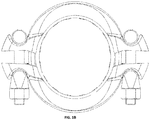
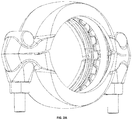
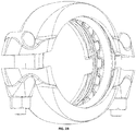
- FIGS. 1 and 2 Tube couplings according to preferred embodiments of the invention are illustrated in FIGS. 1 and 2 .
- a cross section of a tube coupling according to a preferred embodiment of the invention is illustrated in FIG.3 .
- An example of an assembly of a tube coupling which connects two tube segments to each other is illustrated in FIG.4 .
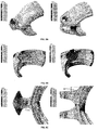
- a tube coupling according to an embodiment of the invention was compared to a tube coupling having a bevelled face, as known from the prior art (always on the right in FIG.5 ).
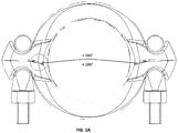
- FIG.5A to FIG.5D The von Mises stresses in the shells at 34 kN are shown in FIG.5A to FIG.5D .
- the largest stress is found with the prior-art tube coupling at the location of contact between the two shells: 526 MPa. This is mainly a compression stress which is of lesser importance for a shell failing.
- the greatest stresses for the prior-art tube coupling are mainly found near the rounding between the bolt face and the remainder of the shell. The stresses here are approximately 417 MPa.
- the tube coupling according to the invention the greatest stresses of interest are found near the bolt which has a maximum value of 455 MPa. Both zones are clearly shown in FIG. 5C . This means that the tube coupling according to the invention has a clamping force which is 9% greater than that of the prior-art tube coupling.
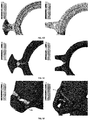
- FIG.5E to FIG.5H show the equivalent plastic strains.
- FIG.5I and FIG.5J show the results in the bolts.
- the tube coupling according to the invention is much more favourable.
- relatively high strains are observed at the location of the bolt connections, but these are still within acceptable limits.
- this critical zone does not change significantly when the prestress increases from 34 to 52.2 kN.
Landscapes
- Engineering & Computer Science (AREA)
- General Engineering & Computer Science (AREA)
- Mechanical Engineering (AREA)
- Joints With Sleeves (AREA)
- Mutual Connection Of Rods And Tubes (AREA)
Applications Claiming Priority (1)
| Application Number | Priority Date | Filing Date | Title |
|---|---|---|---|
| BE20195296A BE1027255B1 (nl) | 2019-05-06 | 2019-05-06 | Buiskoppelingen en het gebruik hiervan |
Publications (3)
| Publication Number | Publication Date |
|---|---|
| EP3736477A1 true EP3736477A1 (fr) | 2020-11-11 |
| EP3736477B1 EP3736477B1 (fr) | 2023-12-06 |
| EP3736477C0 EP3736477C0 (fr) | 2023-12-06 |
Family
ID=66646993
Family Applications (1)
| Application Number | Title | Priority Date | Filing Date |
|---|---|---|---|
| EP20173029.8A Active EP3736477B1 (fr) | 2019-05-06 | 2020-05-05 | Raccords de tuyauterie et leurs utilisations |
Country Status (2)
| Country | Link |
|---|---|
| EP (1) | EP3736477B1 (fr) |
| BE (1) | BE1027255B1 (fr) |
Cited By (2)
| Publication number | Priority date | Publication date | Assignee | Title |
|---|---|---|---|---|
| CN118676814A (zh) * | 2024-08-26 | 2024-09-20 | 东营市昌瑞石油机械配件有限责任公司 | 电泵电缆防护油管固定器 |
| US20250264171A1 (en) * | 2020-11-06 | 2025-08-21 | Victaulic Company | Coupling Having Visual Installation Indicators |
Citations (4)
| Publication number | Priority date | Publication date | Assignee | Title |
|---|---|---|---|---|
| US5415435A (en) * | 1994-02-28 | 1995-05-16 | Colbert; Patrick F. | Pipe coupling support clamp |
| US20070176425A1 (en) * | 2006-02-01 | 2007-08-02 | R.G Ray Corporation | Clamp |
| US20130249212A1 (en) * | 2012-03-26 | 2013-09-26 | ENGINEERED PRODUCT SUPPLY, LLC, d//b/a EPS | Tube or Pipe Clamp |
| KR101380215B1 (ko) * | 2012-10-25 | 2014-04-01 | (주)동아금속 | 자동차 배기파이프용 클램프 및 그 제조방법 |
Family Cites Families (2)
| Publication number | Priority date | Publication date | Assignee | Title |
|---|---|---|---|---|
| US3788677A (en) * | 1972-03-20 | 1974-01-29 | B Stade | Emission-free exhaust pipe joint and clamp therefor |
| US6708377B2 (en) * | 2001-04-30 | 2004-03-23 | Bio Pure Technology Ltd | Tube clamp |
-
2019
- 2019-05-06 BE BE20195296A patent/BE1027255B1/nl active IP Right Grant
-
2020
- 2020-05-05 EP EP20173029.8A patent/EP3736477B1/fr active Active
Patent Citations (4)
| Publication number | Priority date | Publication date | Assignee | Title |
|---|---|---|---|---|
| US5415435A (en) * | 1994-02-28 | 1995-05-16 | Colbert; Patrick F. | Pipe coupling support clamp |
| US20070176425A1 (en) * | 2006-02-01 | 2007-08-02 | R.G Ray Corporation | Clamp |
| US20130249212A1 (en) * | 2012-03-26 | 2013-09-26 | ENGINEERED PRODUCT SUPPLY, LLC, d//b/a EPS | Tube or Pipe Clamp |
| KR101380215B1 (ko) * | 2012-10-25 | 2014-04-01 | (주)동아금속 | 자동차 배기파이프용 클램프 및 그 제조방법 |
Cited By (2)
| Publication number | Priority date | Publication date | Assignee | Title |
|---|---|---|---|---|
| US20250264171A1 (en) * | 2020-11-06 | 2025-08-21 | Victaulic Company | Coupling Having Visual Installation Indicators |
| CN118676814A (zh) * | 2024-08-26 | 2024-09-20 | 东营市昌瑞石油机械配件有限责任公司 | 电泵电缆防护油管固定器 |
Also Published As
| Publication number | Publication date |
|---|---|
| EP3736477B1 (fr) | 2023-12-06 |
| EP3736477C0 (fr) | 2023-12-06 |
| BE1027255A1 (nl) | 2020-12-01 |
| BE1027255B1 (nl) | 2020-12-07 |
Similar Documents
| Publication | Publication Date | Title |
|---|---|---|
| US12486929B2 (en) | Adapter coupling | |
| TWI534381B (zh) | 防止管件與管接頭鬆脫之管接頭 | |
| CA2503231C (fr) | Raccord-union a durabilite amelioree | |
| US4471979A (en) | Quick-connect coupling for thin-walled pipes | |
| KR101672069B1 (ko) | 토크 칼라를 지닌 도관용 피팅 | |
| US3484123A (en) | Reuseable flareless tube coupling | |
| CN100380043C (zh) | 具有卸载作用以减少因磨损而咬住的卡套 | |
| KR102306587B1 (ko) | 파이프 결합구 | |
| KR101916892B1 (ko) | 패스트 그루브 조인트 | |
| KR20120093836A (ko) | 나사식 관 이음 및 나사식 관 이음 제조 방법 | |
| JP2017058018A (ja) | 可撓性トルクカラーを有する導管継手 | |
| US20100102554A1 (en) | Tube Fitting with either Single or Double Ferrule Swage Design Common to One System | |
| CN104813088B (zh) | 具有波纹管形弹性部分的后套圈 | |
| US20120217743A1 (en) | Pipe coupling assembly with sleeve locking tabs and associated methods | |
| EP3736477B1 (fr) | Raccords de tuyauterie et leurs utilisations | |
| CN106415104A (zh) | 凸缘接合部加固夹具 | |
| RU2386888C1 (ru) | Соединение трубопроводов | |
| JP2016080121A (ja) | 管継手 | |
| CN101517302A (zh) | 用于管道固定联结的可分离的法兰和对接法兰装置 | |
| WO2009144359A1 (fr) | Raccord à brides | |
| RU2280209C1 (ru) | Разъемное соединение | |
| JP3229134U (ja) | 金属管の接続構造 | |
| RU195176U1 (ru) | Разъемный зажим | |
| HK40117617A (zh) | 管接头 | |
| RU2575218C2 (ru) | Пресс-фитинг |
Legal Events
| Date | Code | Title | Description |
|---|---|---|---|
| PUAI | Public reference made under article 153(3) epc to a published international application that has entered the european phase |
Free format text: ORIGINAL CODE: 0009012 |
|
| STAA | Information on the status of an ep patent application or granted ep patent |
Free format text: STATUS: THE APPLICATION HAS BEEN PUBLISHED |
|
| AK | Designated contracting states |
Kind code of ref document: A1 Designated state(s): AL AT BE BG CH CY CZ DE DK EE ES FI FR GB GR HR HU IE IS IT LI LT LU LV MC MK MT NL NO PL PT RO RS SE SI SK SM TR |
|
| AX | Request for extension of the european patent |
Extension state: BA ME |
|
| STAA | Information on the status of an ep patent application or granted ep patent |
Free format text: STATUS: REQUEST FOR EXAMINATION WAS MADE |
|
| 17P | Request for examination filed |
Effective date: 20210506 |
|
| RBV | Designated contracting states (corrected) |
Designated state(s): AL AT BE BG CH CY CZ DE DK EE ES FI FR GB GR HR HU IE IS IT LI LT LU LV MC MK MT NL NO PL PT RO RS SE SI SK SM TR |
|
| STAA | Information on the status of an ep patent application or granted ep patent |
Free format text: STATUS: EXAMINATION IS IN PROGRESS |
|
| 17Q | First examination report despatched |
Effective date: 20220929 |
|
| GRAP | Despatch of communication of intention to grant a patent |
Free format text: ORIGINAL CODE: EPIDOSNIGR1 |
|
| STAA | Information on the status of an ep patent application or granted ep patent |
Free format text: STATUS: GRANT OF PATENT IS INTENDED |
|
| INTG | Intention to grant announced |
Effective date: 20230705 |
|
| GRAS | Grant fee paid |
Free format text: ORIGINAL CODE: EPIDOSNIGR3 |
|
| RAP1 | Party data changed (applicant data changed or rights of an application transferred) |
Owner name: PRO PIPING PRODUCTS SRL |
|
| GRAA | (expected) grant |
Free format text: ORIGINAL CODE: 0009210 |
|
| STAA | Information on the status of an ep patent application or granted ep patent |
Free format text: STATUS: THE PATENT HAS BEEN GRANTED |
|
| AK | Designated contracting states |
Kind code of ref document: B1 Designated state(s): AL AT BE BG CH CY CZ DE DK EE ES FI FR GB GR HR HU IE IS IT LI LT LU LV MC MK MT NL NO PL PT RO RS SE SI SK SM TR |
|
| REG | Reference to a national code |
Ref country code: GB Ref legal event code: FG4D |
|
| REG | Reference to a national code |
Ref country code: CH Ref legal event code: EP |
|
| REG | Reference to a national code |
Ref country code: DE Ref legal event code: R096 Ref document number: 602020022179 Country of ref document: DE |
|
| REG | Reference to a national code |
Ref country code: IE Ref legal event code: FG4D |
|
| U01 | Request for unitary effect filed |
Effective date: 20231220 |
|
| U07 | Unitary effect registered |
Designated state(s): AT BE BG DE DK EE FI FR IT LT LU LV MT NL PT SE SI Effective date: 20240108 |
|
| PG25 | Lapsed in a contracting state [announced via postgrant information from national office to epo] |
Ref country code: GR Free format text: LAPSE BECAUSE OF FAILURE TO SUBMIT A TRANSLATION OF THE DESCRIPTION OR TO PAY THE FEE WITHIN THE PRESCRIBED TIME-LIMIT Effective date: 20240307 |
|
| PG25 | Lapsed in a contracting state [announced via postgrant information from national office to epo] |
Ref country code: ES Free format text: LAPSE BECAUSE OF FAILURE TO SUBMIT A TRANSLATION OF THE DESCRIPTION OR TO PAY THE FEE WITHIN THE PRESCRIBED TIME-LIMIT Effective date: 20231206 |
|
| PG25 | Lapsed in a contracting state [announced via postgrant information from national office to epo] |
Ref country code: GR Free format text: LAPSE BECAUSE OF FAILURE TO SUBMIT A TRANSLATION OF THE DESCRIPTION OR TO PAY THE FEE WITHIN THE PRESCRIBED TIME-LIMIT Effective date: 20240307 Ref country code: ES Free format text: LAPSE BECAUSE OF FAILURE TO SUBMIT A TRANSLATION OF THE DESCRIPTION OR TO PAY THE FEE WITHIN THE PRESCRIBED TIME-LIMIT Effective date: 20231206 |
|
| PG25 | Lapsed in a contracting state [announced via postgrant information from national office to epo] |
Ref country code: RS Free format text: LAPSE BECAUSE OF FAILURE TO SUBMIT A TRANSLATION OF THE DESCRIPTION OR TO PAY THE FEE WITHIN THE PRESCRIBED TIME-LIMIT Effective date: 20231206 Ref country code: NO Free format text: LAPSE BECAUSE OF FAILURE TO SUBMIT A TRANSLATION OF THE DESCRIPTION OR TO PAY THE FEE WITHIN THE PRESCRIBED TIME-LIMIT Effective date: 20240306 Ref country code: HR Free format text: LAPSE BECAUSE OF FAILURE TO SUBMIT A TRANSLATION OF THE DESCRIPTION OR TO PAY THE FEE WITHIN THE PRESCRIBED TIME-LIMIT Effective date: 20231206 |
|
| PG25 | Lapsed in a contracting state [announced via postgrant information from national office to epo] |
Ref country code: IS Free format text: LAPSE BECAUSE OF FAILURE TO SUBMIT A TRANSLATION OF THE DESCRIPTION OR TO PAY THE FEE WITHIN THE PRESCRIBED TIME-LIMIT Effective date: 20240406 |
|
| U20 | Renewal fee for the european patent with unitary effect paid |
Year of fee payment: 5 Effective date: 20240527 |
|
| PG25 | Lapsed in a contracting state [announced via postgrant information from national office to epo] |
Ref country code: CZ Free format text: LAPSE BECAUSE OF FAILURE TO SUBMIT A TRANSLATION OF THE DESCRIPTION OR TO PAY THE FEE WITHIN THE PRESCRIBED TIME-LIMIT Effective date: 20231206 |
|
| PG25 | Lapsed in a contracting state [announced via postgrant information from national office to epo] |
Ref country code: SK Free format text: LAPSE BECAUSE OF FAILURE TO SUBMIT A TRANSLATION OF THE DESCRIPTION OR TO PAY THE FEE WITHIN THE PRESCRIBED TIME-LIMIT Effective date: 20231206 |
|
| PG25 | Lapsed in a contracting state [announced via postgrant information from national office to epo] |
Ref country code: SM Free format text: LAPSE BECAUSE OF FAILURE TO SUBMIT A TRANSLATION OF THE DESCRIPTION OR TO PAY THE FEE WITHIN THE PRESCRIBED TIME-LIMIT Effective date: 20231206 Ref country code: SK Free format text: LAPSE BECAUSE OF FAILURE TO SUBMIT A TRANSLATION OF THE DESCRIPTION OR TO PAY THE FEE WITHIN THE PRESCRIBED TIME-LIMIT Effective date: 20231206 Ref country code: RO Free format text: LAPSE BECAUSE OF FAILURE TO SUBMIT A TRANSLATION OF THE DESCRIPTION OR TO PAY THE FEE WITHIN THE PRESCRIBED TIME-LIMIT Effective date: 20231206 Ref country code: IS Free format text: LAPSE BECAUSE OF FAILURE TO SUBMIT A TRANSLATION OF THE DESCRIPTION OR TO PAY THE FEE WITHIN THE PRESCRIBED TIME-LIMIT Effective date: 20240406 Ref country code: CZ Free format text: LAPSE BECAUSE OF FAILURE TO SUBMIT A TRANSLATION OF THE DESCRIPTION OR TO PAY THE FEE WITHIN THE PRESCRIBED TIME-LIMIT Effective date: 20231206 |
|
| PG25 | Lapsed in a contracting state [announced via postgrant information from national office to epo] |
Ref country code: PL Free format text: LAPSE BECAUSE OF FAILURE TO SUBMIT A TRANSLATION OF THE DESCRIPTION OR TO PAY THE FEE WITHIN THE PRESCRIBED TIME-LIMIT Effective date: 20231206 |
|
| PG25 | Lapsed in a contracting state [announced via postgrant information from national office to epo] |
Ref country code: PL Free format text: LAPSE BECAUSE OF FAILURE TO SUBMIT A TRANSLATION OF THE DESCRIPTION OR TO PAY THE FEE WITHIN THE PRESCRIBED TIME-LIMIT Effective date: 20231206 |
|
| REG | Reference to a national code |
Ref country code: DE Ref legal event code: R097 Ref document number: 602020022179 Country of ref document: DE |
|
| PLBE | No opposition filed within time limit |
Free format text: ORIGINAL CODE: 0009261 |
|
| STAA | Information on the status of an ep patent application or granted ep patent |
Free format text: STATUS: NO OPPOSITION FILED WITHIN TIME LIMIT |
|
| 26N | No opposition filed |
Effective date: 20240909 |
|
| REG | Reference to a national code |
Ref country code: CH Ref legal event code: PL |
|
| PG25 | Lapsed in a contracting state [announced via postgrant information from national office to epo] |
Ref country code: MC Free format text: LAPSE BECAUSE OF FAILURE TO SUBMIT A TRANSLATION OF THE DESCRIPTION OR TO PAY THE FEE WITHIN THE PRESCRIBED TIME-LIMIT Effective date: 20231206 |
|
| GBPC | Gb: european patent ceased through non-payment of renewal fee |
Effective date: 20240505 |
|
| PG25 | Lapsed in a contracting state [announced via postgrant information from national office to epo] |
Ref country code: MC Free format text: LAPSE BECAUSE OF FAILURE TO SUBMIT A TRANSLATION OF THE DESCRIPTION OR TO PAY THE FEE WITHIN THE PRESCRIBED TIME-LIMIT Effective date: 20231206 Ref country code: CH Free format text: LAPSE BECAUSE OF NON-PAYMENT OF DUE FEES Effective date: 20240531 |
|
| PG25 | Lapsed in a contracting state [announced via postgrant information from national office to epo] |
Ref country code: IE Free format text: LAPSE BECAUSE OF NON-PAYMENT OF DUE FEES Effective date: 20240505 |
|
| PG25 | Lapsed in a contracting state [announced via postgrant information from national office to epo] |
Ref country code: GB Free format text: LAPSE BECAUSE OF NON-PAYMENT OF DUE FEES Effective date: 20240505 |
|
| U20 | Renewal fee for the european patent with unitary effect paid |
Year of fee payment: 6 Effective date: 20250528 |
|
| PG25 | Lapsed in a contracting state [announced via postgrant information from national office to epo] |
Ref country code: CY Free format text: LAPSE BECAUSE OF FAILURE TO SUBMIT A TRANSLATION OF THE DESCRIPTION OR TO PAY THE FEE WITHIN THE PRESCRIBED TIME-LIMIT; INVALID AB INITIO Effective date: 20200505 |
|
| PG25 | Lapsed in a contracting state [announced via postgrant information from national office to epo] |
Ref country code: HU Free format text: LAPSE BECAUSE OF FAILURE TO SUBMIT A TRANSLATION OF THE DESCRIPTION OR TO PAY THE FEE WITHIN THE PRESCRIBED TIME-LIMIT; INVALID AB INITIO Effective date: 20200505 |