EP3736488A1 - Logement rectangulaire - Google Patents
Logement rectangulaire Download PDFInfo
- Publication number
- EP3736488A1 EP3736488A1 EP19173079.5A EP19173079A EP3736488A1 EP 3736488 A1 EP3736488 A1 EP 3736488A1 EP 19173079 A EP19173079 A EP 19173079A EP 3736488 A1 EP3736488 A1 EP 3736488A1
- Authority
- EP
- European Patent Office
- Prior art keywords
- housing
- hook
- recess
- cover
- rectangular
- Prior art date
- Legal status (The legal status is an assumption and is not a legal conclusion. Google has not performed a legal analysis and makes no representation as to the accuracy of the status listed.)
- Granted
Links
Images
Classifications
-
- F—MECHANICAL ENGINEERING; LIGHTING; HEATING; WEAPONS; BLASTING
- F21—LIGHTING
- F21V—FUNCTIONAL FEATURES OR DETAILS OF LIGHTING DEVICES OR SYSTEMS THEREOF; STRUCTURAL COMBINATIONS OF LIGHTING DEVICES WITH OTHER ARTICLES, NOT OTHERWISE PROVIDED FOR
- F21V17/00—Fastening of component parts of lighting devices, e.g. shades, globes, refractors, reflectors, filters, screens, grids or protective cages
- F21V17/10—Fastening of component parts of lighting devices, e.g. shades, globes, refractors, reflectors, filters, screens, grids or protective cages characterised by specific fastening means or way of fastening
- F21V17/14—Bayonet-type fastening
-
- F—MECHANICAL ENGINEERING; LIGHTING; HEATING; WEAPONS; BLASTING
- F21—LIGHTING
- F21V—FUNCTIONAL FEATURES OR DETAILS OF LIGHTING DEVICES OR SYSTEMS THEREOF; STRUCTURAL COMBINATIONS OF LIGHTING DEVICES WITH OTHER ARTICLES, NOT OTHERWISE PROVIDED FOR
- F21V15/00—Protecting lighting devices from damage
- F21V15/01—Housings, e.g. material or assembling of housing parts
-
- F—MECHANICAL ENGINEERING; LIGHTING; HEATING; WEAPONS; BLASTING
- F21—LIGHTING
- F21S—NON-PORTABLE LIGHTING DEVICES; SYSTEMS THEREOF; VEHICLE LIGHTING DEVICES SPECIALLY ADAPTED FOR VEHICLE EXTERIORS
- F21S8/00—Lighting devices intended for fixed installation
- F21S8/03—Lighting devices intended for fixed installation of surface-mounted type
- F21S8/033—Lighting devices intended for fixed installation of surface-mounted type the surface being a wall or like vertical structure, e.g. building facade
-
- F—MECHANICAL ENGINEERING; LIGHTING; HEATING; WEAPONS; BLASTING
- F21—LIGHTING
- F21V—FUNCTIONAL FEATURES OR DETAILS OF LIGHTING DEVICES OR SYSTEMS THEREOF; STRUCTURAL COMBINATIONS OF LIGHTING DEVICES WITH OTHER ARTICLES, NOT OTHERWISE PROVIDED FOR
- F21V17/00—Fastening of component parts of lighting devices, e.g. shades, globes, refractors, reflectors, filters, screens, grids or protective cages
- F21V17/005—Fastening of component parts of lighting devices, e.g. shades, globes, refractors, reflectors, filters, screens, grids or protective cages with keying means, i.e. for enabling the assembling of component parts in distinctive positions, e.g. for preventing wrong mounting
-
- F—MECHANICAL ENGINEERING; LIGHTING; HEATING; WEAPONS; BLASTING
- F21—LIGHTING
- F21V—FUNCTIONAL FEATURES OR DETAILS OF LIGHTING DEVICES OR SYSTEMS THEREOF; STRUCTURAL COMBINATIONS OF LIGHTING DEVICES WITH OTHER ARTICLES, NOT OTHERWISE PROVIDED FOR
- F21V31/00—Gas-tight or water-tight arrangements
Definitions
- the present invention relates to a rectangular luminaire housing with two opposing short and two opposing long rectangular sides and a cover covering the housing with a light exit opening, fastening means being provided in the corners of the housing and the cover.
- a wide variety of means are known from the prior art for attaching a cover to a housing.
- the cover can be connected to a housing by means of a seal, the fastening being carried out by means of screws, which are mostly arranged in the corners.
- the screws have to be tightened crosswise in order to counteract any distortion of the cover.
- the housing and the cover with latches and recesses assigned to the latches in order to realize a detachable connection.
- Corresponding housings are known from a wide variety of fields, but are not used in the field of lamp housings.
- the object of the present invention is to provide an effective connection between the cover and the housing in which the housing elements are reliably connected to one another and which is easy to assemble and at the same time, if a seal is provided, ensures reliable sealing of the lamp.
- a rectangular luminaire housing with two opposing short and two opposing long rectangular sides and a cover covering the housing with a light exit opening, whereby fastening means cooperating in the corners of the housing and the cover are provided, in that on the long rectangular sides both the cover and the housing between the corners hook-shaped interlocking retaining elements are provided.
- the present invention thus provides a lamp housing which ensures particularly good and uniform fixing of the cover to the housing.
- hook-shaped interlocking retaining elements makes it possible to dispense with further fastening means.
- the hook-shaped holding elements act between the cover and the housing, so that they are not visible from the outside. This makes it possible to provide a housing which is characterized by particularly clear lines. Furthermore, the hook-shaped holding elements can interact without additional tools when connecting the cover to the housing.
- the fastening elements of two corners can also be designed as hook-shaped interlocking holding elements.
- This adapts the overall appearance of the housing and, at the same time, simplifies the fixing of the cover on the housing.
- the various hook-shaped holding elements used can be brought into contact with one another at the same time during a single connecting step. This considerably reduces the assembly time for the housing.
- the hook-shaped holding elements can be arranged in a recess in the area of the cover and / or the housing.
- the arrangement of the hook-shaped retaining elements in a recess ensures that they are fully protected.
- the assembly of the cover on the housing is simplified, since the recesses specifically indicate the area of the hook-shaped holding elements, so that the two elements, cover and housing, can already be placed on top of one another in the correct position.
- the recess is closed at least on the outside of the cover and / or the housing.
- the recess can also be formed like a shaft in the side wall of the housing or in a cover edge, so that the holding elements protrude neither on the outside nor on the inside of the housing or cover.
- the cover has an essentially constant material thickness over its entire surface, the recess can also simply be designed like a shaft in the cover.
- This embodiment supports in particular the guidance of the hook-shaped holding elements when they engage one another. At the same time, it is ensured that the holding elements or fastening elements are arranged within the housing and the cover so that no fastening means are visible from the outside.
- each hook-shaped holding element can be formed in a recess in the area of the cover, a hook being arranged in the area of a side wall.
- This embodiment also facilitates the assembly of the cover on the housing, as the cover can easily be connected to the housing.
- the arrangement of the hooks in the area of a side wall of the recess enables two hooks to automatically engage one another when the cover is moved slightly against the housing.
- each hook-shaped holding element in the area of the housing is designed as a projection in the extension of the side walls, which protrudes into the recess and interacts with the hook of the recess.
- the projection has a thickness which is less than the thickness of the side wall in order to ensure problem-free engagement in the recess in the area of the cover without the holding elements being visible from the outside. If the cover and the housing are connected to one another, the projections can simply be inserted into the recesses in the region of the cover and thus provide a guide.
- the arrangement of the hook-shaped holding elements as an extension of the side walls is particularly simple with regard to production.
- a particularly simple embodiment can provide that the projection is formed on a side wall opposite the hook of the recess with a hook which cooperates with the hook of the recess. When the projection is inserted into the recess, the hooks are automatically aligned with one another and can simply be brought together.
- the hook of the recess and the hook of the projection can be designed with corresponding inclined surfaces which interact in use.
- the two hooks come into contact with one another in the area of the inclined surfaces and can thus be easily moved against one another. This achieves a particularly secure fixation of the cover on the housing.
- the hook elements in the recess and the projection interact by a lateral displacement of the cover against the housing, whereby the cover pulls against the housing.
- the hooks are brought more and more into contact by the displacement, and the cover and the housing are thereby drawn towards one another. Since holding elements are provided not only at the corners, but also in the area of the long sides of the rectangle, this ensures that over the entire area of the housing a complete seal between cover and housing is achieved. At the same time, it is impossible for the cover to deform in relation to the housing.
- the number of additional retaining elements on the long side of the rectangle can be determined depending on the size of the housing.
- the fastening elements of both corners can be designed as hook-shaped interlocking retaining elements, the direction of action of the hook-shaped retaining elements of the fastening elements of the second corner being rotated by 180 ° to the direction of action of the first corner.
- the hook-shaped holding elements of these two corners are consequently arranged in mirror image to one another. This embodiment also serves to simplify assembly.
- the hook-shaped holding element rotated by 180 °, d. H. the hook is provided in the side wall of the recess of the second corner by a screw member.
- a corresponding screw element preferably a grub screw, which can be easily removed from the outside, i.e. H. the short rectangular side of the lid can be screwed in, takes on the task of the hook of the recess.
- the screw element preferably has at its tip an inclined surface which is formed uniformly over the circumference and which interacts continuously with the hook of the projection.
- the hooks of the corners which are arranged in the depressions are arranged on the side wall which faces or is adjacent to the short side of the rectangle. This ensures that the grub screw can be screwed in from the outside. It should be noted that a corresponding grub screw can be screwed in from the side of the housing or the cover which, in use, faces a wall, for example, so that this grub screw is no longer noticeable.
- the width of the projection can be smaller than the clear width of the recess in order to ensure that the projection can be inserted into the recess without any problems.
- the specification relates to the width of the projection including the hook arranged on it.
- the present invention consequently provides a means of fastening which is suitable for housings of any size, including large-area and elongated housings, it being possible to achieve a secure seal over the entire housing. Since the fastening means or holding elements are arranged inside the housing, preferably between the edge of the housing and the cover, they are not visible from the outside, so that the housing is characterized by particularly clear lines. At the same time, it can be ensured that the housing cannot be manipulated from the outside. Corresponding holding elements or fastening elements are also particularly suitable for flat housings, in which the use of screws for fastening is usually impossible due to the dimensions.
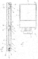
- the lamp housing 1 is shown with a view of the cover 2.
- the lid 2 here has a rectangular shape, comprising two short rectangular sides 3 and two long rectangular sides 4.
- a square light opening 5 is formed, which is arranged in the area of the lid 2 that the light opening 5 over three Edges each have the same distance from the adjacent edge 3, 4 of the cover 2.
- the light opening 5 can be closed here with a material known in the field, for example glass or plastic.
- a wall mounting 6 is arranged in a known manner. Corresponding wall mountings are known in the field, so that these are not explained in more detail.
- FIG 2 is that in Figure 1
- the lamp housing shown is shown in section, with both the cover 2 and the housing 7 being shown.
- the cut is made along a long rectangular side of the lamp housing 1.
- a total of three fasteners / retaining elements 8 are arranged between the cover 2 and the housing 6, two in the corners and another approximately in the middle in the area of the long Rectangular side 4.
- two fastening means / holding means 8 are identical is called a fastening means arranged in a corner and the fastening means 8 arranged in the middle.
- the fastening means / holding means 8 are designed in the area of the cover 2 in the form of a recess 9.
- the recess 9 essentially has a rectangular shape and can be designed as a shaft-shaped recess in the area of a lid edge.
- the recess 9 can, however, also be designed to be open towards the interior of the lamp housing 1.
- a hook 10 is arranged on a side wall of the recess.
- the hook 10 is as in Figure 2 shown, "nose-like", and extends from a corner of the recess obliquely downwards, so that the hook 10 is wider starting from the corner of the recess 10 downwards.
- the hook 10 consequently forms an undercut in the region of the recess 10.
- the hook 10 can be designed with a width which corresponds to the width of the side wall on which the hook 10 is arranged.
- projections 11 are arranged in the region of the housing 7.
- the projections 11 have an angular shape and are formed with a hook 12 on a side wall, that is to say the side wall facing the hook 10 of the recess 9.
- the hook 12 is formed as an extension of the upper side 13 of the projection 11 facing away from the housing and extends along a side wall of the projection 11.
- the projection 11 can be designed with inclined side walls so that the cross-section of the projection resembles the shape of a lying diamond, the inclined surface of the hook 12 also being taken into account.
- the dimensions of the projection 11 are selected in such a way that the projection can be inserted into the recess, ie the clear width of the recess 9 is wider than the width of the projection 11 including hooks.
- the height of the projection 11, in cross section corresponds at most to the depth of the recess 9.
- the third fastening means / holding element 8 which is arranged in the second corner, is designed to be rotated by 180 °.
- the projection 11 arranged on the housing 12 in the region of the second corner consequently inclines away from the other projections 11 in the direction of the second short side 3 'of the rectangle.
- the hook 12 of this projection also points towards the second side of the rectangle 3 ', while the hooks 12 of the other two projections 11 point in the direction of the first short side of the rectangle.
- the recess 9 of the second corner also differs from the other two recesses 9 in that the hook 10 is not formed in one piece with the side wall of the recess, but rather by a screw element, i.e. H. a grub screw 14 is provided and that the recess is also mirror-inverted in cross-section, d. H. the grub screw 14 is arranged on the side wall facing the second short rectangular side 3 '.
- the dimensions of the recess correspond to the dimensions of the other two recesses.
- the grub screw 14 has an inclined surface at its end facing the projection 11; H. it is designed to be pointed, so that the inclined surface of the grub screw 14 can interact with the inclined surface of the hook 12.
- the grub screw 14 is screwed completely into the cover 2 from the second short rectangular side 3 ', so that only the receiving opening 15 of the grub screw 14 is visible from the outside.
- the cover 2 is aligned with the housing 7 in such a way that each projection 11 of the housing is received in a recess 9 in the cover.
- the cover 2 is slightly displaced towards the housing 7, and the two hooks 10, 12 of the recesses 9 or the projections are still arranged next to one another.
- the cover By moving the cover, ie aligning the cover with the circumference of the housing 7, the inclined surfaces of the hooks 10, 12 are then brought into engagement with one another and the hooks slide towards one another on the inclined surface. This movement of the hooks also pulls the cover onto the housing at the same time.
- the cover does not have to be moved manually, but can also be effected or supported by screwing in the grub screw 14.
- the conical lateral surface of the grub screw 14 exerts a pressure on the inclined surface of the hook 12 of the associated projection 11, which pressure is directed in the direction of the first short side 3 of the rectangle. This pressure also moves the inclined surfaces of the other projections 11 towards one another and thus pulls the cover 2 onto the housing 7.
Landscapes
- Engineering & Computer Science (AREA)
- General Engineering & Computer Science (AREA)
- Non-Portable Lighting Devices Or Systems Thereof (AREA)
- Arrangement Of Elements, Cooling, Sealing, Or The Like Of Lighting Devices (AREA)
Priority Applications (1)
| Application Number | Priority Date | Filing Date | Title |
|---|---|---|---|
| EP19173079.5A EP3736488B1 (fr) | 2019-05-07 | 2019-05-07 | Logement rectangulaire |
Applications Claiming Priority (1)
| Application Number | Priority Date | Filing Date | Title |
|---|---|---|---|
| EP19173079.5A EP3736488B1 (fr) | 2019-05-07 | 2019-05-07 | Logement rectangulaire |
Publications (2)
| Publication Number | Publication Date |
|---|---|
| EP3736488A1 true EP3736488A1 (fr) | 2020-11-11 |
| EP3736488B1 EP3736488B1 (fr) | 2021-07-21 |
Family
ID=66554132
Family Applications (1)
| Application Number | Title | Priority Date | Filing Date |
|---|---|---|---|
| EP19173079.5A Active EP3736488B1 (fr) | 2019-05-07 | 2019-05-07 | Logement rectangulaire |
Country Status (1)
| Country | Link |
|---|---|
| EP (1) | EP3736488B1 (fr) |
Cited By (1)
| Publication number | Priority date | Publication date | Assignee | Title |
|---|---|---|---|---|
| CN117161738A (zh) * | 2023-08-09 | 2023-12-05 | 合肥哈工智灵智能科技有限公司 | 两栖探查机器人壳体的装配方法 |
Citations (6)
| Publication number | Priority date | Publication date | Assignee | Title |
|---|---|---|---|---|
| FR2535438A1 (fr) * | 1982-10-29 | 1984-05-04 | Eclairage Tech | Globe pour appareils d'eclairage |
| EP0159145A1 (fr) * | 1984-03-15 | 1985-10-23 | Eterna Lighting Ltd. | Armature lumineuse |
| EP0392217A1 (fr) * | 1989-03-25 | 1990-10-17 | ABB CEAG Licht- und Stromversorgungstechnik GmbH | Armature lumineuse de forme allongée |
| EP1816420A2 (fr) * | 2006-02-06 | 2007-08-08 | BSH Bosch und Siemens Hausgeräte GmbH | Assemblage d' éclairage pour appareil ménager |
| EP2940380A1 (fr) * | 2014-04-29 | 2015-11-04 | Zumtobel Lighting GmbH | Joint |
| US20180224090A1 (en) * | 2015-09-09 | 2018-08-09 | Feng Li | Bolt locking structure for waterproof LED lamp |
-
2019
- 2019-05-07 EP EP19173079.5A patent/EP3736488B1/fr active Active
Patent Citations (6)
| Publication number | Priority date | Publication date | Assignee | Title |
|---|---|---|---|---|
| FR2535438A1 (fr) * | 1982-10-29 | 1984-05-04 | Eclairage Tech | Globe pour appareils d'eclairage |
| EP0159145A1 (fr) * | 1984-03-15 | 1985-10-23 | Eterna Lighting Ltd. | Armature lumineuse |
| EP0392217A1 (fr) * | 1989-03-25 | 1990-10-17 | ABB CEAG Licht- und Stromversorgungstechnik GmbH | Armature lumineuse de forme allongée |
| EP1816420A2 (fr) * | 2006-02-06 | 2007-08-08 | BSH Bosch und Siemens Hausgeräte GmbH | Assemblage d' éclairage pour appareil ménager |
| EP2940380A1 (fr) * | 2014-04-29 | 2015-11-04 | Zumtobel Lighting GmbH | Joint |
| US20180224090A1 (en) * | 2015-09-09 | 2018-08-09 | Feng Li | Bolt locking structure for waterproof LED lamp |
Cited By (1)
| Publication number | Priority date | Publication date | Assignee | Title |
|---|---|---|---|---|
| CN117161738A (zh) * | 2023-08-09 | 2023-12-05 | 合肥哈工智灵智能科技有限公司 | 两栖探查机器人壳体的装配方法 |
Also Published As
| Publication number | Publication date |
|---|---|
| EP3736488B1 (fr) | 2021-07-21 |
Similar Documents
| Publication | Publication Date | Title |
|---|---|---|
| DE69209087T2 (de) | Lüftungsvorrichtung | |
| AT392884B (de) | Moebelverbinder | |
| DE4101363C1 (fr) | ||
| EP3736488B1 (fr) | Logement rectangulaire | |
| DE2436844C2 (de) | Befestigungsmittel für ein Beschlagteil an Metall- oder Kunststoff-Hohlprofilen, insbesondere an Tür- oder Fensterflügeln und -rahmen | |
| DE4201570C2 (de) | Stellvorrichtung | |
| DE2648089C2 (de) | Blindplatte für Geräteabdeckung | |
| DE3214915C2 (fr) | ||
| EP3524103A1 (fr) | Support pour fleurs et produits décoratifs sur les battants de fenêtre et de porte | |
| DE102014016899B3 (de) | Hebe-Senk-Scharnier sowie Tür mit Hebe-Senk-Scharnier | |
| AT520803A1 (de) | Schubladenseitenwand | |
| DE2907049A1 (de) | Elektrische einbaudose | |
| DE29602613U1 (de) | Vorrichtung zum druckfesten Dichten einer Tür | |
| DE29508292U1 (de) | Befehlsgerät | |
| DE69905814T2 (de) | Verstellbare Eck-Verbindung für Kabelkanäle | |
| DE10313842B4 (de) | Schranktür | |
| DE4013441A1 (de) | Stangenfuehrung fuer die stangen eines stangenverschlusses | |
| DE7025049U (de) | Verbindungsorgane zur befestigung eines blendrahmens an einer mauerzange. | |
| EP1944448B1 (fr) | Dispositif de fixation destiné à la fixation d'une extrémité d'un moyen de transmission de puissance sur un élément de construction mobile | |
| DE7731551U1 (de) | Staubdichtes Gehäuse, insbesondere für elektrische Anlagen | |
| DE202009013622U1 (de) | Winkelformteil für Kabelkanäle | |
| DE202018000700U1 (de) | Halterung für Blumen und Dekorationswaren an Fenster- und Türflügeln | |
| DE2839974A1 (de) | Rahmenloser bildtraeger | |
| AT391353B (de) | Verbinder zum verbinden zweier bauelemente | |
| DE3609992A1 (de) | Tuerzarge zur ummantelung von metallzargen |
Legal Events
| Date | Code | Title | Description |
|---|---|---|---|
| PUAI | Public reference made under article 153(3) epc to a published international application that has entered the european phase |
Free format text: ORIGINAL CODE: 0009012 |
|
| STAA | Information on the status of an ep patent application or granted ep patent |
Free format text: STATUS: REQUEST FOR EXAMINATION WAS MADE |
|
| 17P | Request for examination filed |
Effective date: 20190507 |
|
| AK | Designated contracting states |
Kind code of ref document: A1 Designated state(s): AL AT BE BG CH CY CZ DE DK EE ES FI FR GB GR HR HU IE IS IT LI LT LU LV MC MK MT NL NO PL PT RO RS SE SI SK SM TR |
|
| AX | Request for extension of the european patent |
Extension state: BA ME |
|
| RIC1 | Information provided on ipc code assigned before grant |
Ipc: F21V 17/14 20060101ALI20210302BHEP Ipc: F21S 8/00 20060101ALN20210302BHEP Ipc: F21V 15/01 20060101AFI20210302BHEP Ipc: F21V 17/00 20060101ALN20210302BHEP Ipc: F21V 31/00 20060101ALN20210302BHEP |
|
| GRAP | Despatch of communication of intention to grant a patent |
Free format text: ORIGINAL CODE: EPIDOSNIGR1 |
|
| STAA | Information on the status of an ep patent application or granted ep patent |
Free format text: STATUS: GRANT OF PATENT IS INTENDED |
|
| INTG | Intention to grant announced |
Effective date: 20210412 |
|
| GRAS | Grant fee paid |
Free format text: ORIGINAL CODE: EPIDOSNIGR3 |
|
| GRAA | (expected) grant |
Free format text: ORIGINAL CODE: 0009210 |
|
| STAA | Information on the status of an ep patent application or granted ep patent |
Free format text: STATUS: THE PATENT HAS BEEN GRANTED |
|
| AK | Designated contracting states |
Kind code of ref document: B1 Designated state(s): AL AT BE BG CH CY CZ DE DK EE ES FI FR GB GR HR HU IE IS IT LI LT LU LV MC MK MT NL NO PL PT RO RS SE SI SK SM TR |
|
| REG | Reference to a national code |
Ref country code: GB Ref legal event code: FG4D Free format text: NOT ENGLISH |
|
| REG | Reference to a national code |
Ref country code: HK Ref legal event code: DE Ref document number: 40040499 Country of ref document: HK Ref country code: CH Ref legal event code: EP |
|
| REG | Reference to a national code |
Ref country code: DE Ref legal event code: R096 Ref document number: 502019001838 Country of ref document: DE |
|
| REG | Reference to a national code |
Ref country code: AT Ref legal event code: REF Ref document number: 1412913 Country of ref document: AT Kind code of ref document: T Effective date: 20210815 |
|
| REG | Reference to a national code |
Ref country code: IE Ref legal event code: FG4D Free format text: LANGUAGE OF EP DOCUMENT: GERMAN |
|
| REG | Reference to a national code |
Ref country code: LT Ref legal event code: MG9D |
|
| REG | Reference to a national code |
Ref country code: NL Ref legal event code: MP Effective date: 20210721 |
|
| PG25 | Lapsed in a contracting state [announced via postgrant information from national office to epo] |
Ref country code: LT Free format text: LAPSE BECAUSE OF FAILURE TO SUBMIT A TRANSLATION OF THE DESCRIPTION OR TO PAY THE FEE WITHIN THE PRESCRIBED TIME-LIMIT Effective date: 20210721 Ref country code: BG Free format text: LAPSE BECAUSE OF FAILURE TO SUBMIT A TRANSLATION OF THE DESCRIPTION OR TO PAY THE FEE WITHIN THE PRESCRIBED TIME-LIMIT Effective date: 20211021 Ref country code: HR Free format text: LAPSE BECAUSE OF FAILURE TO SUBMIT A TRANSLATION OF THE DESCRIPTION OR TO PAY THE FEE WITHIN THE PRESCRIBED TIME-LIMIT Effective date: 20210721 Ref country code: NL Free format text: LAPSE BECAUSE OF FAILURE TO SUBMIT A TRANSLATION OF THE DESCRIPTION OR TO PAY THE FEE WITHIN THE PRESCRIBED TIME-LIMIT Effective date: 20210721 Ref country code: NO Free format text: LAPSE BECAUSE OF FAILURE TO SUBMIT A TRANSLATION OF THE DESCRIPTION OR TO PAY THE FEE WITHIN THE PRESCRIBED TIME-LIMIT Effective date: 20211021 Ref country code: PT Free format text: LAPSE BECAUSE OF FAILURE TO SUBMIT A TRANSLATION OF THE DESCRIPTION OR TO PAY THE FEE WITHIN THE PRESCRIBED TIME-LIMIT Effective date: 20211122 Ref country code: ES Free format text: LAPSE BECAUSE OF FAILURE TO SUBMIT A TRANSLATION OF THE DESCRIPTION OR TO PAY THE FEE WITHIN THE PRESCRIBED TIME-LIMIT Effective date: 20210721 Ref country code: FI Free format text: LAPSE BECAUSE OF FAILURE TO SUBMIT A TRANSLATION OF THE DESCRIPTION OR TO PAY THE FEE WITHIN THE PRESCRIBED TIME-LIMIT Effective date: 20210721 Ref country code: RS Free format text: LAPSE BECAUSE OF FAILURE TO SUBMIT A TRANSLATION OF THE DESCRIPTION OR TO PAY THE FEE WITHIN THE PRESCRIBED TIME-LIMIT Effective date: 20210721 Ref country code: SE Free format text: LAPSE BECAUSE OF FAILURE TO SUBMIT A TRANSLATION OF THE DESCRIPTION OR TO PAY THE FEE WITHIN THE PRESCRIBED TIME-LIMIT Effective date: 20210721 |
|
| PG25 | Lapsed in a contracting state [announced via postgrant information from national office to epo] |
Ref country code: PL Free format text: LAPSE BECAUSE OF FAILURE TO SUBMIT A TRANSLATION OF THE DESCRIPTION OR TO PAY THE FEE WITHIN THE PRESCRIBED TIME-LIMIT Effective date: 20210721 Ref country code: LV Free format text: LAPSE BECAUSE OF FAILURE TO SUBMIT A TRANSLATION OF THE DESCRIPTION OR TO PAY THE FEE WITHIN THE PRESCRIBED TIME-LIMIT Effective date: 20210721 Ref country code: GR Free format text: LAPSE BECAUSE OF FAILURE TO SUBMIT A TRANSLATION OF THE DESCRIPTION OR TO PAY THE FEE WITHIN THE PRESCRIBED TIME-LIMIT Effective date: 20211022 |
|
| REG | Reference to a national code |
Ref country code: DE Ref legal event code: R097 Ref document number: 502019001838 Country of ref document: DE |
|
| PG25 | Lapsed in a contracting state [announced via postgrant information from national office to epo] |
Ref country code: DK Free format text: LAPSE BECAUSE OF FAILURE TO SUBMIT A TRANSLATION OF THE DESCRIPTION OR TO PAY THE FEE WITHIN THE PRESCRIBED TIME-LIMIT Effective date: 20210721 |
|
| PLBE | No opposition filed within time limit |
Free format text: ORIGINAL CODE: 0009261 |
|
| STAA | Information on the status of an ep patent application or granted ep patent |
Free format text: STATUS: NO OPPOSITION FILED WITHIN TIME LIMIT |
|
| PG25 | Lapsed in a contracting state [announced via postgrant information from national office to epo] |
Ref country code: SM Free format text: LAPSE BECAUSE OF FAILURE TO SUBMIT A TRANSLATION OF THE DESCRIPTION OR TO PAY THE FEE WITHIN THE PRESCRIBED TIME-LIMIT Effective date: 20210721 Ref country code: SK Free format text: LAPSE BECAUSE OF FAILURE TO SUBMIT A TRANSLATION OF THE DESCRIPTION OR TO PAY THE FEE WITHIN THE PRESCRIBED TIME-LIMIT Effective date: 20210721 Ref country code: RO Free format text: LAPSE BECAUSE OF FAILURE TO SUBMIT A TRANSLATION OF THE DESCRIPTION OR TO PAY THE FEE WITHIN THE PRESCRIBED TIME-LIMIT Effective date: 20210721 Ref country code: EE Free format text: LAPSE BECAUSE OF FAILURE TO SUBMIT A TRANSLATION OF THE DESCRIPTION OR TO PAY THE FEE WITHIN THE PRESCRIBED TIME-LIMIT Effective date: 20210721 Ref country code: CZ Free format text: LAPSE BECAUSE OF FAILURE TO SUBMIT A TRANSLATION OF THE DESCRIPTION OR TO PAY THE FEE WITHIN THE PRESCRIBED TIME-LIMIT Effective date: 20210721 Ref country code: AL Free format text: LAPSE BECAUSE OF FAILURE TO SUBMIT A TRANSLATION OF THE DESCRIPTION OR TO PAY THE FEE WITHIN THE PRESCRIBED TIME-LIMIT Effective date: 20210721 |
|
| 26N | No opposition filed |
Effective date: 20220422 |
|
| REG | Reference to a national code |
Ref country code: CH Ref legal event code: PL |
|
| REG | Reference to a national code |
Ref country code: BE Ref legal event code: MM Effective date: 20220531 |
|
| PG25 | Lapsed in a contracting state [announced via postgrant information from national office to epo] |
Ref country code: MC Free format text: LAPSE BECAUSE OF FAILURE TO SUBMIT A TRANSLATION OF THE DESCRIPTION OR TO PAY THE FEE WITHIN THE PRESCRIBED TIME-LIMIT Effective date: 20210721 Ref country code: LU Free format text: LAPSE BECAUSE OF NON-PAYMENT OF DUE FEES Effective date: 20220507 Ref country code: LI Free format text: LAPSE BECAUSE OF NON-PAYMENT OF DUE FEES Effective date: 20220531 Ref country code: CH Free format text: LAPSE BECAUSE OF NON-PAYMENT OF DUE FEES Effective date: 20220531 |
|
| PG25 | Lapsed in a contracting state [announced via postgrant information from national office to epo] |
Ref country code: IE Free format text: LAPSE BECAUSE OF NON-PAYMENT OF DUE FEES Effective date: 20220507 |
|
| PG25 | Lapsed in a contracting state [announced via postgrant information from national office to epo] |
Ref country code: BE Free format text: LAPSE BECAUSE OF NON-PAYMENT OF DUE FEES Effective date: 20220531 |
|
| PG25 | Lapsed in a contracting state [announced via postgrant information from national office to epo] |
Ref country code: MK Free format text: LAPSE BECAUSE OF FAILURE TO SUBMIT A TRANSLATION OF THE DESCRIPTION OR TO PAY THE FEE WITHIN THE PRESCRIBED TIME-LIMIT Effective date: 20210721 Ref country code: CY Free format text: LAPSE BECAUSE OF FAILURE TO SUBMIT A TRANSLATION OF THE DESCRIPTION OR TO PAY THE FEE WITHIN THE PRESCRIBED TIME-LIMIT Effective date: 20210721 |
|
| PG25 | Lapsed in a contracting state [announced via postgrant information from national office to epo] |
Ref country code: HU Free format text: LAPSE BECAUSE OF FAILURE TO SUBMIT A TRANSLATION OF THE DESCRIPTION OR TO PAY THE FEE WITHIN THE PRESCRIBED TIME-LIMIT; INVALID AB INITIO Effective date: 20190507 |
|
| PG25 | Lapsed in a contracting state [announced via postgrant information from national office to epo] |
Ref country code: MT Free format text: LAPSE BECAUSE OF FAILURE TO SUBMIT A TRANSLATION OF THE DESCRIPTION OR TO PAY THE FEE WITHIN THE PRESCRIBED TIME-LIMIT Effective date: 20210721 |
|
| PGFP | Annual fee paid to national office [announced via postgrant information from national office to epo] |
Ref country code: DE Payment date: 20250528 Year of fee payment: 7 |
|
| PGFP | Annual fee paid to national office [announced via postgrant information from national office to epo] |
Ref country code: GB Payment date: 20250524 Year of fee payment: 7 |
|
| PGFP | Annual fee paid to national office [announced via postgrant information from national office to epo] |
Ref country code: IT Payment date: 20250529 Year of fee payment: 7 |
|
| PGFP | Annual fee paid to national office [announced via postgrant information from national office to epo] |
Ref country code: FR Payment date: 20250520 Year of fee payment: 7 |
|
| PGFP | Annual fee paid to national office [announced via postgrant information from national office to epo] |
Ref country code: AT Payment date: 20250526 Year of fee payment: 7 |
|
| PG25 | Lapsed in a contracting state [announced via postgrant information from national office to epo] |
Ref country code: TR Free format text: LAPSE BECAUSE OF FAILURE TO SUBMIT A TRANSLATION OF THE DESCRIPTION OR TO PAY THE FEE WITHIN THE PRESCRIBED TIME-LIMIT Effective date: 20210721 |
|
| REG | Reference to a national code |
Ref country code: DE Ref legal event code: R082 Ref document number: 502019001838 Country of ref document: DE Representative=s name: HABERMANN INTELLECTUAL PROPERTY PARTNERSCHAFT , DE |