EP3736605A2 - Balayeur laser de sécurité et procédé - Google Patents
Balayeur laser de sécurité et procédé Download PDFInfo
- Publication number
- EP3736605A2 EP3736605A2 EP20170153.9A EP20170153A EP3736605A2 EP 3736605 A2 EP3736605 A2 EP 3736605A2 EP 20170153 A EP20170153 A EP 20170153A EP 3736605 A2 EP3736605 A2 EP 3736605A2
- Authority
- EP
- European Patent Office
- Prior art keywords
- laser scanner
- safety
- light beam
- light
- signal
- Prior art date
- Legal status (The legal status is an assumption and is not a legal conclusion. Google has not performed a legal analysis and makes no representation as to the accuracy of the status listed.)
- Granted
Links
Images
Classifications
-
- G—PHYSICS
- G01—MEASURING; TESTING
- G01S—RADIO DIRECTION-FINDING; RADIO NAVIGATION; DETERMINING DISTANCE OR VELOCITY BY USE OF RADIO WAVES; LOCATING OR PRESENCE-DETECTING BY USE OF THE REFLECTION OR RERADIATION OF RADIO WAVES; ANALOGOUS ARRANGEMENTS USING OTHER WAVES
- G01S17/00—Systems using the reflection or reradiation of electromagnetic waves other than radio waves, e.g. lidar systems
- G01S17/02—Systems using the reflection of electromagnetic waves other than radio waves
- G01S17/06—Systems determining position data of a target
- G01S17/42—Simultaneous measurement of distance and other co-ordinates
-
- G—PHYSICS
- G01—MEASURING; TESTING
- G01S—RADIO DIRECTION-FINDING; RADIO NAVIGATION; DETERMINING DISTANCE OR VELOCITY BY USE OF RADIO WAVES; LOCATING OR PRESENCE-DETECTING BY USE OF THE REFLECTION OR RERADIATION OF RADIO WAVES; ANALOGOUS ARRANGEMENTS USING OTHER WAVES
- G01S17/00—Systems using the reflection or reradiation of electromagnetic waves other than radio waves, e.g. lidar systems
- G01S17/88—Lidar systems specially adapted for specific applications
-
- G—PHYSICS
- G01—MEASURING; TESTING
- G01S—RADIO DIRECTION-FINDING; RADIO NAVIGATION; DETERMINING DISTANCE OR VELOCITY BY USE OF RADIO WAVES; LOCATING OR PRESENCE-DETECTING BY USE OF THE REFLECTION OR RERADIATION OF RADIO WAVES; ANALOGOUS ARRANGEMENTS USING OTHER WAVES
- G01S7/00—Details of systems according to groups G01S13/00, G01S15/00, G01S17/00
- G01S7/48—Details of systems according to groups G01S13/00, G01S15/00, G01S17/00 of systems according to group G01S17/00
- G01S7/481—Constructional features, e.g. arrangements of optical elements
- G01S7/4817—Constructional features, e.g. arrangements of optical elements relating to scanning
-
- G—PHYSICS
- G01—MEASURING; TESTING
- G01S—RADIO DIRECTION-FINDING; RADIO NAVIGATION; DETERMINING DISTANCE OR VELOCITY BY USE OF RADIO WAVES; LOCATING OR PRESENCE-DETECTING BY USE OF THE REFLECTION OR RERADIATION OF RADIO WAVES; ANALOGOUS ARRANGEMENTS USING OTHER WAVES
- G01S7/00—Details of systems according to groups G01S13/00, G01S15/00, G01S17/00
- G01S7/48—Details of systems according to groups G01S13/00, G01S15/00, G01S17/00 of systems according to group G01S17/00
- G01S7/497—Means for monitoring or calibrating
- G01S2007/4975—Means for monitoring or calibrating of sensor obstruction by, e.g. dirt- or ice-coating, e.g. by reflection measurement on front-screen
Definitions
- the invention relates to a safety laser scanner and a method for detecting objects in a surveillance area according to the preamble of claim 1 and claim 10, respectively.
- a light beam generated by a laser periodically sweeps over a monitored area with the aid of a deflection unit.
- the light is reflected on objects in the monitored area and evaluated in the laser scanner.
- the angular position of the object is determined from the angular position of the deflection unit and the distance of the object from the laser scanner is also deduced from the time of flight using the speed of light.
- two basic principles are known for determining the time of flight. With phase-based methods, the continuous transmitted light is modulated and the phase shift of the received compared to the transmitted light is evaluated.
- the transmitter works in single-pulse mode with relatively high pulse energies, and the laser scanner measures object distances based on the time-of-flight between sending and receiving a single light pulse. For example, from the EP 2 469 296 B1 Known pulse averaging methods, a large number of individual pulses are sent out for a measurement and the received pulses are statistically evaluated.
- the location of an object in the monitoring area is recorded in two-dimensional polar coordinates. This allows the positions of objects or their contours to be determined.
- the third Spatial coordinates can also be detected by a relative movement in the transverse direction, for example by a further degree of freedom of movement of the deflection unit in the laser scanner or by conveying the object relative to the laser scanner. In this way, three-dimensional contours can also be measured.
- Safety laser scanners are not used for general measuring tasks, but in safety technology or personal protection to monitor a source of danger, such as that represented by a dangerous machine.
- a safety laser scanner is from DE 43 40 756 A1 known.
- a protective field is monitored, which the operating personnel must not enter while the machine is in operation. If the safety laser scanner detects an impermissible protective field intervention, for example an operator's leg, it triggers an emergency stop of the machine.
- Other interventions in the protective field for example by static machine parts, can be taught in as permissible in advance. Warning fields are often in front of the protective fields, where interventions initially only lead to a warning in order to prevent the protective field intervention and thus the protection in time and thus increase the availability of the system.
- Safety laser scanners usually work on a pulse basis.
- Safety laser scanners must work particularly reliably and therefore meet high safety requirements, for example the EN13849 standard for machine safety and the EN61496 device standard for electro-sensitive protective devices (ESPE).
- ESE electro-sensitive protective devices
- a number of measures must be taken, such as safe electronic evaluation through redundant, diverse electronics, function monitoring or, in particular, monitoring of the contamination of optical components, in particular a front window.
- the requirements for self-diagnosis vary depending on the risk potential, which is expressed, for example, by so-called performance levels.
- One of the measures to meet the relevant standards is the use of an internal reference target, with the help of which the error-free distance measurement and its unimpaired sensitivity can be checked.
- the reference target is optically touched in each revolution of the deflection unit and the signal echo in view evaluated for signal strength and distance value. If this self-test turns out negative, the device switches off in a safety-related manner. It is common to use a contiguous angular range exclusively for the reference target measurement.
- the carrier on which the deflection unit with motor, rotating mirror and angle encoder is suspended is also located in this angular range.
- a self-test can be subject to errors of the first and second type.
- a first type of error would be that the system no longer works, but the self-test does not reveal this. It is essential to avoid this in a security system.
- a typical requirement is single-fault security, i.e. the system fails to recognize such an error only in the extremely unlikely event that two errors happen to occur at the same time that are not due to a common cause.
- An error of the second type means that a safety-related shutdown takes place although the system is objectively still fully functional. This is never a safety problem and is therefore much less critical, but it reduces availability and leads to undesirable and costly downtimes as well as unnecessary repairs or device replacements.
- the EP 0 843 180 B1 discloses a safety laser scanner with a special, multi-part, internal reference target that comprises several individual targets, each of which has differently strong remission properties. Problems due to the enormous signal dynamics can thus be better controlled, because these signal dynamics can be simulated, tested and thus controlled with the various individual targets. Further problem cases cannot be recorded with it.
- this object is achieved by a safety laser scanner for detecting objects in a monitoring area according to claim 1.
- a safety laser scanner is a safe laser scanner in the sense of a safety standard as described in the introduction and may therefore be used for personal protection at sources of danger.
- the safety laser scanner has a light transmitter for emitting a light beam into the surveillance area, a light receiver for generating a received signal from the light beam remitted by the objects, a rotatable deflection unit for periodically deflecting the light beam in order to scan the surveillance area in the course of movement, an internal reference target that throws back the emitted light beam within the safety laser scanner to the light receiver in order to generate a reference signal and a control and evaluation unit which is designed to detect objects using the received signal and to check the functionality of the safety laser scanner using the reference signal.
- control and evaluation unit is designed to detect an intensity distribution of the reference signal when the light beam sweeps over the one reference target and further designed, if the shape of the intensity distribution of the reference signal deviates from a predefined reference shape of the intensity distribution beyond a predetermined tolerance, a warning signal to spend.
- the invention is based on the basic idea of using the reference signal not only for monitoring or for the self-test of the scanner, but also to detect and evaluate a form of intensity distribution when the light beam sweeps over the reference target. In this way it can be recognized, for example, whether there is condensation on the reference target, that is to say whether moisture is present or has entered the interior of the safety laser scanner. Moisture is undesirable because moisture can endanger operation and the functionality or service life of internal components, in particular optical and electronic components, is then reduced.
- the moisture can be recognized by the shape of the intensity distribution, because condensation on optical elements is caused by the optical system predetermined intensity distribution washed out, i.e. broadened, due to the light scattering by the water droplets.
- This effect of changing the shape of the intensity distribution and its use in the acquisition and evaluation of the reference signal is an essential element of the invention.
- An additional, further check, namely whether and how much moisture is present, i.e. whether and how much condensation is present on the reference target, the lens and / or mirror optics inside the scanner, can thus be carried out by means of the reference signal.
- Further advantages are an improvement in maintainability, since it is possible to check whether condensation has occurred in the device, the possibility of estimating maintenance intervals (predictive maintenance), evidence of proper use in the event of a fault and the recording of environmental data to optimize systems and machines. The task is thus solved.
- the shape of the intensity distribution can even provide at least a qualitative statement about the degree of condensation, because the more moisture condenses on the reference target, the flatter the distribution.
- a measure of the condensation on the reference target can thus be derived from the intensity distribution.
- the warning signal can thus reflect the degree of humidity inside the safety laser scanner.
- the shape of the intensity distribution is determined by the cross section of the light beam and the aperture of the reference target. It makes sense to record the reference shape during the manufacture of the safety laser scanner in a learning process and to save it in the control and evaluation unit. In such a teach-in process, the tolerance can also be entered or saved, which is the current measured shape of the reference shape, within which no warning message is given.
- the reference target is advantageously designed as a light guide, the coupling surface forming the aperture that the light beam sweeps over.
- the light guide guides the coupled light to the light receiver. In this embodiment, it is in principle not important where the aperture of the reference target is arranged exactly, which can be advantageous for the positioning of the light transmitter and light receiver.
- the reference target is designed as a flat target with a uniform degree of reflection. The light is then simply reflected or remitted at the reference target and mapped onto the light receiver.
- an inexpensive humidity sensor that is typically functionally unsafe can be used, for example based on the capacitive or resistive principle.
- the combination of reference target-based moisture measurement or dew point determination and moisture sensor makes it possible to quantify the moisture content at all temperature working points.
- the additional sensor supplies a signal for quantitative evaluation and the evaluation of the reference target measurement curve is used for functionally safe qualitative validation.
- the safety laser scanner is preferably designed as a range finder in that the control and evaluation unit determines the time of flight between transmission and reception of the light beam and, from this, the distance to an object. In this way, much more precise object information can be obtained than by simply determining the presence of objects.
- An angle measuring unit is preferably provided for detecting the angular position of the deflection unit. Overall, complete two-dimensional position coordinates are then available for detected objects. In the case of a spatially extended monitoring area, the respective tilt angle of the scanning unit is also recorded, so that overall three-dimensional spherical coordinates are obtained which also completely describe the object position within the monitoring area.
- the control and evaluation unit is preferably designed to measure the distance to the internal reference target when checking the functionality. This also checks the distance measurement which, if the safety laser scanner is working correctly, gives the expected distance for the reference target.
- the reference signal in particular is evaluated in the same way as a received signal.
- the measuring core it makes no difference whether the emitted light beam is reflected externally on a measuring object or internally on the reference target. It is only known, for example, because of the current adjustment angle of the deflection unit corresponding to the blind spot area with the reference target, that it is a reference measurement.
- the safety laser scanner preferably has a safety output, the control and evaluation unit being designed to determine whether an object is located in a protective field within the monitoring area and then to output a safety-related switch-off signal via the safety output.
- the safety evaluation is already integrated in the safety laser scanner, which directly provides a safety-related switch-off signal for a machine or an interconnected safety controller.
- the control and evaluation unit is preferably designed to output a safety-related switch-off signal via the safety output if the checking of the functionality does not result in an error-free function.
- the safety shutdown also takes place if the self-test via the reference target measurement reveals a problem. This can be a reference target measured at the wrong distance or moisture detected by changing the shape of the distribution.
- the warning signal can thus be expanded to include a quantitative value, which is particularly useful in terms of predictive maintenance.
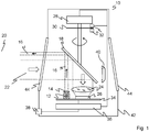
- Fig. 1 shows a schematic sectional illustration through a safety laser scanner 10.
- Safety laser scanner 10 means that use in personal protection is possible, that is, measures have been taken in accordance with the standards mentioned in the introduction that rule out an undetected failure of the function according to the security level or performance level.
- a light transmitter 12 for example with a laser light source, generates a transmission light beam 16 with the aid of transmission optics 14, which beam is deflected at a deflection unit 18 into a monitoring area 20. If the transmitted light beam 16 falls on an object in the monitoring area 20, the reflected light 22 returns to the safety laser scanner 10 and is detected there via the deflection unit 18 and by means of receiving optics 24 by a light receiver 26, for example a photodiode or an APD (Avalanche Photo Diode).
- a light receiver 26 for example a photodiode or an APD (Avalanche Photo Diode).
- the deflection unit 18 is designed as a rotating mirror which rotates continuously by driving a motor 28.
- the respective angular position of the motor 28 or of the deflection unit 18 is detected by an encoder, which comprises, for example, a code disk 30 and a fork light barrier 32.
- the transmitted light beam 16 generated by the light transmitter 12 thus sweeps over the monitoring area 20 generated by the rotational movement.
- the design of the transmitting optics 14 and receiving optics 24 can also be varied, for example using a beam-shaping mirror as a deflection unit, a different arrangement of the lenses or additional lenses.
- safety laser scanners are also known in a coaxial arrangement, that is to say with a common optical axis of light transmitter 12 and light receiver 26.
- light transmitter 12 and light receiver 26 are accommodated together on a circuit board 34. This is also only one example, because separate circuit cards and other arrangements, for example with a mutual height offset, can be provided.
- the angular position of the deflection unit 18 measured by the encoder 30, 32 can be used to deduce the angular position of the object in the monitoring area 20.
- the light transit time is preferred from the transmission of a light signal to its reception after reflection on the object in the monitoring area 20 and, using the speed of light, inferred the distance of the object from the safety laser scanner 10.
- This evaluation takes place in an evaluation unit 36 which is connected to the light transmitter 12, the light receiver 26, the motor 28 and the encoder 32 for this purpose. Two-dimensional polar coordinates of all objects in the monitored area 20 are thus available via the angle and the distance.
- the evaluation unit 36 checks whether an impermissible object encroaches on a protection area defined within the monitoring area 20. If this is the case, a safety signal is output to a monitored source of danger, for example a machine, via a safety output 38 (OSSD, Output Signal Switching Device).
- OSSD Output Signal Switching Device
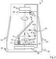
- a reference target 40 is arranged in an angular range of the safety laser scanner 10, which is in the Fig. 1 just offset by 180 ° to the transmitted light beam 16 and remitted light 22 Fig. 1 is shown. If the deflection unit 18 assumes corresponding angular positions in the course of its rotational movement, the transmitted light beam 16 does not leave the safety laser scanner 10, but is reflected within the safety laser scanner 10 from the reference target 40, as shown in FIG Fig. 2 is shown. The light beam 16 then strikes an aperture or coupling surface 41a of the reference target 40 at a specific angle ⁇ .
- the reference target 40 is designed as a light guide.
- the light beam is guided through the light guide to a light output 41b and leaves the reference target in the direction of the deflection unit 18 and is deflected by this onto the receiver.
- the reference target 40 is designed here as a light guide so that the light beam 16 is reflected with an offset so that it hits the receiver 26.
- the light receiver 26 does not generate a received signal for detection of objects in the monitoring area 20, but a reference signal that is usually used for a functional check.
- the reference signal is evaluated in order, on the one hand, to check the functionality of the safety laser scanner 10. This test preferably takes place once per revolution of the deflection unit 18 in short cycles. If the control and evaluation unit does not measure the reference target 40 at the expected distance, this is an error and the safety laser scanner 10 goes into the safety state with the output of a safety-related shutdown signal at the safety output 38.
- the reference signal according to the invention is observed, recorded and evaluated as described below:
- the light beam 16 sweeps across the aperture 41a of the reference target 40.
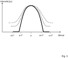
- the temporal intensity profile which corresponds to a constant angle change that the light receiver 26 sees with uniform rotation, which is usually present, has a qualitative profile as it does in Fig. 3 is shown with reference numeral 60.
- the exact quantitative course depends on the geometric relationships, such as the size and shape of the aperture and diameter of the light beam 16. This is the normal case, that is to say without interference. The course is roughly Gaussian.
- the intensity distribution 60 for this undisturbed normal case is referred to as the reference form of the intensity distribution.
- the intensity distributions 60, 62, 64 are detected, recorded and evaluated by the control and evaluation unit 36. In the evaluation, it is checked whether the deviation of a currently recorded form of an intensity distribution, e.g. 62 or 64, from the reference shape 60 beyond a predetermined amount, that is to say a predetermined tolerance. If this is the case, the moisture content is no longer tolerable and a warning signal is output by the control and evaluation unit.
- This warning signal can be an external signal so that service personnel clean / dehumidify the safety laser scanner 10. But it could also simply be an internal signal, e.g. controls a heater or prompts you to replace an optional desiccant cartridge.
- the control and evaluation unit 36 is preferably designed, from the recorded intensity distribution 62, 64 a measure of condensation on the reference target 40 and thus for the moisture content in the interior of the housing 42.
- the warning signal can thus reflect the degree of humidity inside the safety laser scanner and communicate to the outside.
- the reference shape 60 of the intensity distribution is, as explained, dependent on geometric relationships. It is therefore sensible for a specific safety laser scanner 10 to teach-in and store the reference shape in a teach-in process, preferably within the scope of manufacture. In this procedure, the tolerance can also be specified, which thus indicates the moisture content or degree of condensation from which the warning signal should be output.
- the reference target 40 does not necessarily have to be designed as a light guide.
- the light guide is only selected in the illustrated embodiment because transmitter 12 and receiver 26 are arranged next to one another.
- a simple reflector can serve as a reference target.
- An intensity distribution with a reference shape only needs to be present qualitatively when the light beam 16 is passed over it.
Landscapes
- Engineering & Computer Science (AREA)
- Physics & Mathematics (AREA)
- Computer Networks & Wireless Communication (AREA)
- General Physics & Mathematics (AREA)
- Radar, Positioning & Navigation (AREA)
- Remote Sensing (AREA)
- Electromagnetism (AREA)
- Optical Radar Systems And Details Thereof (AREA)
Applications Claiming Priority (1)
| Application Number | Priority Date | Filing Date | Title |
|---|---|---|---|
| DE102019111852.2A DE102019111852B3 (de) | 2019-05-07 | 2019-05-07 | Sicherheitslaserscanner und Verfahren |
Publications (3)
| Publication Number | Publication Date |
|---|---|
| EP3736605A2 true EP3736605A2 (fr) | 2020-11-11 |
| EP3736605A3 EP3736605A3 (fr) | 2021-02-24 |
| EP3736605B1 EP3736605B1 (fr) | 2021-06-16 |
Family
ID=70295057
Family Applications (1)
| Application Number | Title | Priority Date | Filing Date |
|---|---|---|---|
| EP20170153.9A Active EP3736605B1 (fr) | 2019-05-07 | 2020-04-17 | Balayeur laser de sécurité et procédé |
Country Status (3)
| Country | Link |
|---|---|
| EP (1) | EP3736605B1 (fr) |
| DE (1) | DE102019111852B3 (fr) |
| DK (1) | DK3736605T3 (fr) |
Families Citing this family (3)
| Publication number | Priority date | Publication date | Assignee | Title |
|---|---|---|---|---|
| DE102021116581A1 (de) * | 2020-10-16 | 2022-04-21 | Zoller & Fröhlich GmbH | Laserscanner |
| WO2022168903A1 (fr) * | 2021-02-03 | 2022-08-11 | パイオニア株式会社 | Dispositif de détection d'anomalie, procédé de détection d'anomalie et programme |
| DE102023111319A1 (de) | 2023-05-02 | 2024-11-07 | Universität Kassel, Körperschaft des öffentlichen Rechts | Diagnosevorrichtung für eine scannende Lidar-Messvorrichtung |
Citations (4)
| Publication number | Priority date | Publication date | Assignee | Title |
|---|---|---|---|---|
| DE4340756A1 (de) | 1992-12-08 | 1994-06-09 | Sick Optik Elektronik Erwin | Laserabstandsermittlungsvorrichtung |
| EP0843180B1 (fr) | 1996-11-14 | 2001-08-01 | Sick AG | Télémétrie |
| EP2469296B1 (fr) | 2010-12-21 | 2012-10-24 | Sick AG | Capteur optoélectronique et procédé destiné à la détection et la détermination de l'éloignement d'objets |
| DE202012101007U1 (de) | 2012-03-21 | 2013-06-24 | Sick Ag | Optoelektronischer Sensor |
Family Cites Families (4)
| Publication number | Priority date | Publication date | Assignee | Title |
|---|---|---|---|---|
| DE4219260C2 (de) * | 1992-06-12 | 1994-07-14 | Leuze Electronic Gmbh & Co | Lichtelektrische Vorrichtung mit einem Testobjekt |
| JP4819403B2 (ja) * | 2005-06-06 | 2011-11-24 | 株式会社トプコン | 距離測定装置 |
| EP2112527A3 (fr) * | 2008-04-22 | 2011-06-22 | Riegl Laser Measurement Systems GmbH | Cible de référence destinée au calibrage de scanners laser |
| DE102014109618A1 (de) | 2014-07-09 | 2016-01-14 | Sick Ag | Sensor mit Kondensationsfalle |
-
2019
- 2019-05-07 DE DE102019111852.2A patent/DE102019111852B3/de active Active
-
2020
- 2020-04-17 EP EP20170153.9A patent/EP3736605B1/fr active Active
- 2020-04-17 DK DK20170153.9T patent/DK3736605T3/da active
Patent Citations (4)
| Publication number | Priority date | Publication date | Assignee | Title |
|---|---|---|---|---|
| DE4340756A1 (de) | 1992-12-08 | 1994-06-09 | Sick Optik Elektronik Erwin | Laserabstandsermittlungsvorrichtung |
| EP0843180B1 (fr) | 1996-11-14 | 2001-08-01 | Sick AG | Télémétrie |
| EP2469296B1 (fr) | 2010-12-21 | 2012-10-24 | Sick AG | Capteur optoélectronique et procédé destiné à la détection et la détermination de l'éloignement d'objets |
| DE202012101007U1 (de) | 2012-03-21 | 2013-06-24 | Sick Ag | Optoelektronischer Sensor |
Also Published As
| Publication number | Publication date |
|---|---|
| DK3736605T3 (da) | 2021-08-02 |
| EP3736605B1 (fr) | 2021-06-16 |
| DE102019111852B3 (de) | 2020-06-04 |
| EP3736605A3 (fr) | 2021-02-24 |
Similar Documents
| Publication | Publication Date | Title |
|---|---|---|
| EP3637136B1 (fr) | Balayeur laser de sécurité et procédé de maintien de la capacité de fonctionnement | |
| EP2482094B1 (fr) | Capteur optoélectronique mesurant l'éloignement et procédé de détection d'objet | |
| EP2362243B1 (fr) | Capteur optoélectronique | |
| EP2378309B1 (fr) | Capteur optoélectronique et procédé de production d'informations sur des objets dans une zone de surveillance | |
| EP3736605B1 (fr) | Balayeur laser de sécurité et procédé | |
| EP3367135B1 (fr) | Capteur optique | |
| EP3163322B1 (fr) | Scanner laser et procédé de vérification de sa capacité de fonctionnement | |
| EP3862780B1 (fr) | Balayeur laser de sécurité et procédé de surveillance de vitre frontale | |
| DE102015105264A1 (de) | Optoelektronischer Sensor und Verfahren zur Transmissionsüberwachung einer Frontscheibe | |
| EP3671264B1 (fr) | Capteur et procédé de détection d'un objet | |
| EP2698649B1 (fr) | Capteur de surveillance doté d'un contrôle automatique | |
| EP3330741B1 (fr) | Capteur optoélectronique et procédé de détection d'objets dans une zone de détection | |
| EP3588139A1 (fr) | Capteur optoélectronique et procédé de détermination de la distance | |
| EP0875873B1 (fr) | Capteur opto-électronique | |
| EP2703837B1 (fr) | Scanner laser de sécurité | |
| EP3415951B1 (fr) | Capteur optique | |
| EP3623849B1 (fr) | Capteur optique | |
| EP2637036B1 (fr) | Module complémentaire destiné au montage sur un capteur optique et procédé de fonctionnement d'un capteur optique | |
| DE102022130166B4 (de) | Sicherheitssystem und Verfahren mit einem Sicherheitssystem | |
| EP3392679B1 (fr) | Capteur optique | |
| EP1959271B1 (fr) | Agencement de capteur optoélectrique et procédé de vérification du mode de fonctionnement et/ou de l'ajustement d'un agencement de capteur optoélectronique | |
| EP2515143A1 (fr) | Procédé de détection et de détermination de position sécurisée d'objets et dispositif de sécurité | |
| EP3367129B1 (fr) | Capteur optoélectronique et procédé de détection d'objets | |
| EP4382953B1 (fr) | Capteur optoélectronique et procédé de détection et de détermination de distance d'objets | |
| DE202019100793U1 (de) | Optoelektronischer Sensor zur Erfassung von Objekten |
Legal Events
| Date | Code | Title | Description |
|---|---|---|---|
| PUAI | Public reference made under article 153(3) epc to a published international application that has entered the european phase |
Free format text: ORIGINAL CODE: 0009012 |
|
| STAA | Information on the status of an ep patent application or granted ep patent |
Free format text: STATUS: THE APPLICATION HAS BEEN PUBLISHED |
|
| STAA | Information on the status of an ep patent application or granted ep patent |
Free format text: STATUS: REQUEST FOR EXAMINATION WAS MADE |
|
| AK | Designated contracting states |
Kind code of ref document: A2 Designated state(s): AL AT BE BG CH CY CZ DE DK EE ES FI FR GB GR HR HU IE IS IT LI LT LU LV MC MK MT NL NO PL PT RO RS SE SI SK SM TR |
|
| AX | Request for extension of the european patent |
Extension state: BA ME |
|
| 17P | Request for examination filed |
Effective date: 20201021 |
|
| RBV | Designated contracting states (corrected) |
Designated state(s): AL AT BE BG CH CY CZ DE DK EE ES FI FR GB GR HR HU IE IS IT LI LT LU LV MC MK MT NL NO PL PT RO RS SE SI SK SM TR |
|
| PUAL | Search report despatched |
Free format text: ORIGINAL CODE: 0009013 |
|
| AK | Designated contracting states |
Kind code of ref document: A3 Designated state(s): AL AT BE BG CH CY CZ DE DK EE ES FI FR GB GR HR HU IE IS IT LI LT LU LV MC MK MT NL NO PL PT RO RS SE SI SK SM TR |
|
| AX | Request for extension of the european patent |
Extension state: BA ME |
|
| RIC1 | Information provided on ipc code assigned before grant |
Ipc: G01S 17/88 20060101ALI20210118BHEP Ipc: G01S 17/42 20060101AFI20210118BHEP Ipc: G01S 7/497 20060101ALI20210118BHEP Ipc: G01S 7/481 20060101ALI20210118BHEP |
|
| GRAP | Despatch of communication of intention to grant a patent |
Free format text: ORIGINAL CODE: EPIDOSNIGR1 |
|
| STAA | Information on the status of an ep patent application or granted ep patent |
Free format text: STATUS: GRANT OF PATENT IS INTENDED |
|
| INTG | Intention to grant announced |
Effective date: 20210408 |
|
| GRAS | Grant fee paid |
Free format text: ORIGINAL CODE: EPIDOSNIGR3 |
|
| GRAA | (expected) grant |
Free format text: ORIGINAL CODE: 0009210 |
|
| STAA | Information on the status of an ep patent application or granted ep patent |
Free format text: STATUS: THE PATENT HAS BEEN GRANTED |
|
| AK | Designated contracting states |
Kind code of ref document: B1 Designated state(s): AL AT BE BG CH CY CZ DE DK EE ES FI FR GB GR HR HU IE IS IT LI LT LU LV MC MK MT NL NO PL PT RO RS SE SI SK SM TR |
|
| REG | Reference to a national code |
Ref country code: GB Ref legal event code: FG4D Free format text: NOT ENGLISH |
|
| REG | Reference to a national code |
Ref country code: CH Ref legal event code: EP |
|
| REG | Reference to a national code |
Ref country code: DE Ref legal event code: R096 Ref document number: 502020000058 Country of ref document: DE |
|
| REG | Reference to a national code |
Ref country code: AT Ref legal event code: REF Ref document number: 1402787 Country of ref document: AT Kind code of ref document: T Effective date: 20210715 |
|
| REG | Reference to a national code |
Ref country code: IE Ref legal event code: FG4D Free format text: LANGUAGE OF EP DOCUMENT: GERMAN |
|
| REG | Reference to a national code |
Ref country code: DK Ref legal event code: T3 Effective date: 20210727 |
|
| REG | Reference to a national code |
Ref country code: LT Ref legal event code: MG9D |
|
| PG25 | Lapsed in a contracting state [announced via postgrant information from national office to epo] |
Ref country code: FI Free format text: LAPSE BECAUSE OF FAILURE TO SUBMIT A TRANSLATION OF THE DESCRIPTION OR TO PAY THE FEE WITHIN THE PRESCRIBED TIME-LIMIT Effective date: 20210616 Ref country code: HR Free format text: LAPSE BECAUSE OF FAILURE TO SUBMIT A TRANSLATION OF THE DESCRIPTION OR TO PAY THE FEE WITHIN THE PRESCRIBED TIME-LIMIT Effective date: 20210616 Ref country code: LT Free format text: LAPSE BECAUSE OF FAILURE TO SUBMIT A TRANSLATION OF THE DESCRIPTION OR TO PAY THE FEE WITHIN THE PRESCRIBED TIME-LIMIT Effective date: 20210616 Ref country code: BG Free format text: LAPSE BECAUSE OF FAILURE TO SUBMIT A TRANSLATION OF THE DESCRIPTION OR TO PAY THE FEE WITHIN THE PRESCRIBED TIME-LIMIT Effective date: 20210916 |
|
| REG | Reference to a national code |
Ref country code: NL Ref legal event code: MP Effective date: 20210616 |
|
| PG25 | Lapsed in a contracting state [announced via postgrant information from national office to epo] |
Ref country code: NO Free format text: LAPSE BECAUSE OF FAILURE TO SUBMIT A TRANSLATION OF THE DESCRIPTION OR TO PAY THE FEE WITHIN THE PRESCRIBED TIME-LIMIT Effective date: 20210916 Ref country code: LV Free format text: LAPSE BECAUSE OF FAILURE TO SUBMIT A TRANSLATION OF THE DESCRIPTION OR TO PAY THE FEE WITHIN THE PRESCRIBED TIME-LIMIT Effective date: 20210616 Ref country code: RS Free format text: LAPSE BECAUSE OF FAILURE TO SUBMIT A TRANSLATION OF THE DESCRIPTION OR TO PAY THE FEE WITHIN THE PRESCRIBED TIME-LIMIT Effective date: 20210616 Ref country code: SE Free format text: LAPSE BECAUSE OF FAILURE TO SUBMIT A TRANSLATION OF THE DESCRIPTION OR TO PAY THE FEE WITHIN THE PRESCRIBED TIME-LIMIT Effective date: 20210616 Ref country code: GR Free format text: LAPSE BECAUSE OF FAILURE TO SUBMIT A TRANSLATION OF THE DESCRIPTION OR TO PAY THE FEE WITHIN THE PRESCRIBED TIME-LIMIT Effective date: 20210917 |
|
| PG25 | Lapsed in a contracting state [announced via postgrant information from national office to epo] |
Ref country code: SM Free format text: LAPSE BECAUSE OF FAILURE TO SUBMIT A TRANSLATION OF THE DESCRIPTION OR TO PAY THE FEE WITHIN THE PRESCRIBED TIME-LIMIT Effective date: 20210616 Ref country code: RO Free format text: LAPSE BECAUSE OF FAILURE TO SUBMIT A TRANSLATION OF THE DESCRIPTION OR TO PAY THE FEE WITHIN THE PRESCRIBED TIME-LIMIT Effective date: 20210616 Ref country code: PT Free format text: LAPSE BECAUSE OF FAILURE TO SUBMIT A TRANSLATION OF THE DESCRIPTION OR TO PAY THE FEE WITHIN THE PRESCRIBED TIME-LIMIT Effective date: 20211018 Ref country code: NL Free format text: LAPSE BECAUSE OF FAILURE TO SUBMIT A TRANSLATION OF THE DESCRIPTION OR TO PAY THE FEE WITHIN THE PRESCRIBED TIME-LIMIT Effective date: 20210616 Ref country code: CZ Free format text: LAPSE BECAUSE OF FAILURE TO SUBMIT A TRANSLATION OF THE DESCRIPTION OR TO PAY THE FEE WITHIN THE PRESCRIBED TIME-LIMIT Effective date: 20210616 Ref country code: SK Free format text: LAPSE BECAUSE OF FAILURE TO SUBMIT A TRANSLATION OF THE DESCRIPTION OR TO PAY THE FEE WITHIN THE PRESCRIBED TIME-LIMIT Effective date: 20210616 Ref country code: ES Free format text: LAPSE BECAUSE OF FAILURE TO SUBMIT A TRANSLATION OF THE DESCRIPTION OR TO PAY THE FEE WITHIN THE PRESCRIBED TIME-LIMIT Effective date: 20210616 Ref country code: EE Free format text: LAPSE BECAUSE OF FAILURE TO SUBMIT A TRANSLATION OF THE DESCRIPTION OR TO PAY THE FEE WITHIN THE PRESCRIBED TIME-LIMIT Effective date: 20210616 |
|
| PG25 | Lapsed in a contracting state [announced via postgrant information from national office to epo] |
Ref country code: PL Free format text: LAPSE BECAUSE OF FAILURE TO SUBMIT A TRANSLATION OF THE DESCRIPTION OR TO PAY THE FEE WITHIN THE PRESCRIBED TIME-LIMIT Effective date: 20210616 |
|
| REG | Reference to a national code |
Ref country code: DE Ref legal event code: R097 Ref document number: 502020000058 Country of ref document: DE |
|
| PLBE | No opposition filed within time limit |
Free format text: ORIGINAL CODE: 0009261 |
|
| STAA | Information on the status of an ep patent application or granted ep patent |
Free format text: STATUS: NO OPPOSITION FILED WITHIN TIME LIMIT |
|
| 26N | No opposition filed |
Effective date: 20220317 |
|
| PG25 | Lapsed in a contracting state [announced via postgrant information from national office to epo] |
Ref country code: AL Free format text: LAPSE BECAUSE OF FAILURE TO SUBMIT A TRANSLATION OF THE DESCRIPTION OR TO PAY THE FEE WITHIN THE PRESCRIBED TIME-LIMIT Effective date: 20210616 |
|
| REG | Reference to a national code |
Ref country code: BE Ref legal event code: MM Effective date: 20220430 |
|
| PG25 | Lapsed in a contracting state [announced via postgrant information from national office to epo] |
Ref country code: MC Free format text: LAPSE BECAUSE OF FAILURE TO SUBMIT A TRANSLATION OF THE DESCRIPTION OR TO PAY THE FEE WITHIN THE PRESCRIBED TIME-LIMIT Effective date: 20210616 Ref country code: LU Free format text: LAPSE BECAUSE OF NON-PAYMENT OF DUE FEES Effective date: 20220417 |
|
| PG25 | Lapsed in a contracting state [announced via postgrant information from national office to epo] |
Ref country code: BE Free format text: LAPSE BECAUSE OF NON-PAYMENT OF DUE FEES Effective date: 20220430 |
|
| PG25 | Lapsed in a contracting state [announced via postgrant information from national office to epo] |
Ref country code: IE Free format text: LAPSE BECAUSE OF NON-PAYMENT OF DUE FEES Effective date: 20220417 |
|
| PG25 | Lapsed in a contracting state [announced via postgrant information from national office to epo] |
Ref country code: MK Free format text: LAPSE BECAUSE OF FAILURE TO SUBMIT A TRANSLATION OF THE DESCRIPTION OR TO PAY THE FEE WITHIN THE PRESCRIBED TIME-LIMIT Effective date: 20210616 Ref country code: CY Free format text: LAPSE BECAUSE OF FAILURE TO SUBMIT A TRANSLATION OF THE DESCRIPTION OR TO PAY THE FEE WITHIN THE PRESCRIBED TIME-LIMIT Effective date: 20210616 |
|
| PG25 | Lapsed in a contracting state [announced via postgrant information from national office to epo] |
Ref country code: HU Free format text: LAPSE BECAUSE OF FAILURE TO SUBMIT A TRANSLATION OF THE DESCRIPTION OR TO PAY THE FEE WITHIN THE PRESCRIBED TIME-LIMIT; INVALID AB INITIO Effective date: 20200417 |
|
| PG25 | Lapsed in a contracting state [announced via postgrant information from national office to epo] |
Ref country code: TR Free format text: LAPSE BECAUSE OF FAILURE TO SUBMIT A TRANSLATION OF THE DESCRIPTION OR TO PAY THE FEE WITHIN THE PRESCRIBED TIME-LIMIT Effective date: 20210616 |
|
| PG25 | Lapsed in a contracting state [announced via postgrant information from national office to epo] |
Ref country code: MT Free format text: LAPSE BECAUSE OF FAILURE TO SUBMIT A TRANSLATION OF THE DESCRIPTION OR TO PAY THE FEE WITHIN THE PRESCRIBED TIME-LIMIT Effective date: 20210616 |
|
| PGFP | Annual fee paid to national office [announced via postgrant information from national office to epo] |
Ref country code: DE Payment date: 20250417 Year of fee payment: 6 |
|
| PGFP | Annual fee paid to national office [announced via postgrant information from national office to epo] |
Ref country code: DK Payment date: 20250423 Year of fee payment: 6 |
|
| PGFP | Annual fee paid to national office [announced via postgrant information from national office to epo] |
Ref country code: IT Payment date: 20250430 Year of fee payment: 6 |
|
| PGFP | Annual fee paid to national office [announced via postgrant information from national office to epo] |
Ref country code: FR Payment date: 20250422 Year of fee payment: 6 |
|
| PGFP | Annual fee paid to national office [announced via postgrant information from national office to epo] |
Ref country code: CH Payment date: 20250501 Year of fee payment: 6 |
|
| PGFP | Annual fee paid to national office [announced via postgrant information from national office to epo] |
Ref country code: AT Payment date: 20250721 Year of fee payment: 5 |
|
| PGFP | Annual fee paid to national office [announced via postgrant information from national office to epo] |
Ref country code: GB Payment date: 20260324 Year of fee payment: 7 |