EP3736629A1 - Système de source de lumière et appareil de projection - Google Patents
Système de source de lumière et appareil de projection Download PDFInfo
- Publication number
- EP3736629A1 EP3736629A1 EP18898308.4A EP18898308A EP3736629A1 EP 3736629 A1 EP3736629 A1 EP 3736629A1 EP 18898308 A EP18898308 A EP 18898308A EP 3736629 A1 EP3736629 A1 EP 3736629A1
- Authority
- EP
- European Patent Office
- Prior art keywords
- light source
- laser light
- light
- blue laser
- blue
- Prior art date
- Legal status (The legal status is an assumption and is not a legal conclusion. Google has not performed a legal analysis and makes no representation as to the accuracy of the status listed.)
- Granted
Links
Images


Classifications
-
- G—PHYSICS
- G03—PHOTOGRAPHY; CINEMATOGRAPHY; ANALOGOUS TECHNIQUES USING WAVES OTHER THAN OPTICAL WAVES; ELECTROGRAPHY; HOLOGRAPHY
- G03B—APPARATUS OR ARRANGEMENTS FOR TAKING PHOTOGRAPHS OR FOR PROJECTING OR VIEWING THEM; APPARATUS OR ARRANGEMENTS EMPLOYING ANALOGOUS TECHNIQUES USING WAVES OTHER THAN OPTICAL WAVES; ACCESSORIES THEREFOR
- G03B21/00—Projectors or projection-type viewers; Accessories therefor
- G03B21/14—Details
- G03B21/20—Lamp housings
- G03B21/2006—Lamp housings characterised by the light source
- G03B21/2033—LED or laser light sources
- G03B21/204—LED or laser light sources using secondary light emission, e.g. luminescence or fluorescence
-
- H—ELECTRICITY
- H04—ELECTRIC COMMUNICATION TECHNIQUE
- H04N—PICTORIAL COMMUNICATION, e.g. TELEVISION
- H04N9/00—Details of colour television systems
- H04N9/12—Picture reproducers
- H04N9/31—Projection devices for colour picture display, e.g. using electronic spatial light modulators [ESLM]
- H04N9/3141—Constructional details thereof
- H04N9/315—Modulator illumination systems
- H04N9/3158—Modulator illumination systems for controlling the spectrum
-
- G—PHYSICS
- G02—OPTICS
- G02B—OPTICAL ELEMENTS, SYSTEMS OR APPARATUS
- G02B27/00—Optical systems or apparatus not provided for by any of the groups G02B1/00 - G02B26/00, G02B30/00
- G02B27/10—Beam splitting or combining systems
- G02B27/1006—Beam splitting or combining systems for splitting or combining different wavelengths
-
- G—PHYSICS
- G03—PHOTOGRAPHY; CINEMATOGRAPHY; ANALOGOUS TECHNIQUES USING WAVES OTHER THAN OPTICAL WAVES; ELECTROGRAPHY; HOLOGRAPHY
- G03B—APPARATUS OR ARRANGEMENTS FOR TAKING PHOTOGRAPHS OR FOR PROJECTING OR VIEWING THEM; APPARATUS OR ARRANGEMENTS EMPLOYING ANALOGOUS TECHNIQUES USING WAVES OTHER THAN OPTICAL WAVES; ACCESSORIES THEREFOR
- G03B21/00—Projectors or projection-type viewers; Accessories therefor
- G03B21/14—Details
- G03B21/20—Lamp housings
- G03B21/2006—Lamp housings characterised by the light source
- G03B21/2013—Plural light sources
-
- G—PHYSICS
- G03—PHOTOGRAPHY; CINEMATOGRAPHY; ANALOGOUS TECHNIQUES USING WAVES OTHER THAN OPTICAL WAVES; ELECTROGRAPHY; HOLOGRAPHY
- G03B—APPARATUS OR ARRANGEMENTS FOR TAKING PHOTOGRAPHS OR FOR PROJECTING OR VIEWING THEM; APPARATUS OR ARRANGEMENTS EMPLOYING ANALOGOUS TECHNIQUES USING WAVES OTHER THAN OPTICAL WAVES; ACCESSORIES THEREFOR
- G03B21/00—Projectors or projection-type viewers; Accessories therefor
- G03B21/14—Details
- G03B21/20—Lamp housings
- G03B21/206—Control of light source other than position or intensity
-
- G—PHYSICS
- G03—PHOTOGRAPHY; CINEMATOGRAPHY; ANALOGOUS TECHNIQUES USING WAVES OTHER THAN OPTICAL WAVES; ELECTROGRAPHY; HOLOGRAPHY
- G03B—APPARATUS OR ARRANGEMENTS FOR TAKING PHOTOGRAPHS OR FOR PROJECTING OR VIEWING THEM; APPARATUS OR ARRANGEMENTS EMPLOYING ANALOGOUS TECHNIQUES USING WAVES OTHER THAN OPTICAL WAVES; ACCESSORIES THEREFOR
- G03B21/00—Projectors or projection-type viewers; Accessories therefor
- G03B21/14—Details
- G03B21/20—Lamp housings
- G03B21/2066—Reflectors in illumination beam
-
- G—PHYSICS
- G03—PHOTOGRAPHY; CINEMATOGRAPHY; ANALOGOUS TECHNIQUES USING WAVES OTHER THAN OPTICAL WAVES; ELECTROGRAPHY; HOLOGRAPHY
- G03B—APPARATUS OR ARRANGEMENTS FOR TAKING PHOTOGRAPHS OR FOR PROJECTING OR VIEWING THEM; APPARATUS OR ARRANGEMENTS EMPLOYING ANALOGOUS TECHNIQUES USING WAVES OTHER THAN OPTICAL WAVES; ACCESSORIES THEREFOR
- G03B21/00—Projectors or projection-type viewers; Accessories therefor
- G03B21/14—Details
- G03B21/20—Lamp housings
- G03B21/208—Homogenising, shaping of the illumination light
-
- G—PHYSICS
- G03—PHOTOGRAPHY; CINEMATOGRAPHY; ANALOGOUS TECHNIQUES USING WAVES OTHER THAN OPTICAL WAVES; ELECTROGRAPHY; HOLOGRAPHY
- G03B—APPARATUS OR ARRANGEMENTS FOR TAKING PHOTOGRAPHS OR FOR PROJECTING OR VIEWING THEM; APPARATUS OR ARRANGEMENTS EMPLOYING ANALOGOUS TECHNIQUES USING WAVES OTHER THAN OPTICAL WAVES; ACCESSORIES THEREFOR
- G03B33/00—Colour photography, other than mere exposure or projection of a colour film
- G03B33/08—Sequential recording or projection
-
- H—ELECTRICITY
- H04—ELECTRIC COMMUNICATION TECHNIQUE
- H04N—PICTORIAL COMMUNICATION, e.g. TELEVISION
- H04N9/00—Details of colour television systems
- H04N9/12—Picture reproducers
- H04N9/31—Projection devices for colour picture display, e.g. using electronic spatial light modulators [ESLM]
- H04N9/3141—Constructional details thereof
- H04N9/315—Modulator illumination systems
- H04N9/3152—Modulator illumination systems for shaping the light beam
-
- H—ELECTRICITY
- H04—ELECTRIC COMMUNICATION TECHNIQUE
- H04N—PICTORIAL COMMUNICATION, e.g. TELEVISION
- H04N9/00—Details of colour television systems
- H04N9/12—Picture reproducers
- H04N9/31—Projection devices for colour picture display, e.g. using electronic spatial light modulators [ESLM]
- H04N9/3141—Constructional details thereof
- H04N9/315—Modulator illumination systems
- H04N9/3155—Modulator illumination systems for controlling the light source
-
- H—ELECTRICITY
- H04—ELECTRIC COMMUNICATION TECHNIQUE
- H04N—PICTORIAL COMMUNICATION, e.g. TELEVISION
- H04N9/00—Details of colour television systems
- H04N9/12—Picture reproducers
- H04N9/31—Projection devices for colour picture display, e.g. using electronic spatial light modulators [ESLM]
- H04N9/3141—Constructional details thereof
- H04N9/315—Modulator illumination systems
- H04N9/3161—Modulator illumination systems using laser light sources
-
- H—ELECTRICITY
- H04—ELECTRIC COMMUNICATION TECHNIQUE
- H04N—PICTORIAL COMMUNICATION, e.g. TELEVISION
- H04N9/00—Details of colour television systems
- H04N9/12—Picture reproducers
- H04N9/31—Projection devices for colour picture display, e.g. using electronic spatial light modulators [ESLM]
- H04N9/3141—Constructional details thereof
- H04N9/315—Modulator illumination systems
- H04N9/3164—Modulator illumination systems using multiple light sources
-
- H—ELECTRICITY
- H04—ELECTRIC COMMUNICATION TECHNIQUE
- H04N—PICTORIAL COMMUNICATION, e.g. TELEVISION
- H04N9/00—Details of colour television systems
- H04N9/12—Picture reproducers
- H04N9/31—Projection devices for colour picture display, e.g. using electronic spatial light modulators [ESLM]
- H04N9/3179—Video signal processing therefor
- H04N9/3182—Colour adjustment, e.g. white balance, shading or gamut
Definitions
- the present disclosure relates to the field of projection technology and, in particular, to a light source system and a projection apparatus.
- one projection apparatus when being applied in different occasions, color gamut requirements for projection or reproduction equipment are different.
- one projection apparatus generally can support only one of color gamut standards in the existing projection field. For example, only a DCI color gamut or only a Rec. 2020 color gamut is supported, and dynamic color gamut adjustment of various color gamuts cannot be achieved in one projection or reproduction equipment.
- the present disclosure provides a light source system, and color coordinates of light source light emitted by the light source system can be dynamically adjusted.
- the present disclosure also provides a projection apparatus including the light source system, which can realize dynamic color gamut adjustment.
- a light source system includes a first light source, a second light source comprising a second blue laser light source, a wavelength conversion element, and a controller.
- the first light source includes a first blue laser light source configured to emit first blue laser light, a red laser light source configured to emit red laser light, and a green laser light source configured to emit green laser light.
- the wavelength conversion element is configured to convert second blue laser light into excited light.
- the controller is configured to turn on or turn off the first blue laser light source, the red laser light source, the green laser light source and the second blue laser light source so as to combine the first blue laser light, the red laser light, and the green laser light to form light source light, or to combine the first blue laser light and the excited light to form the light source light.
- a projection device includes the light source system as described above.
- the controller provided by the present disclosure turns on or off the first blue laser light source, the second blue laser light, the red laser light, and the green laser light so that the light source system and the projection apparatus including the light source system can adjust the dynamic color gamut.
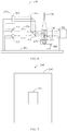
- FIG. 1 is a schematic diagram of a light source system 100 according to a first embodiment of the present disclosure.
- the light source system 100 includes a first light source 110, a second light source 120, a wavelength conversion element 180, a controller 125, an adjustment device 130, a first light splitting and combining element 140, a relay lens 150, a second light splitting and combining element 160, a collecting lens group 170 and a light homogenizing device 190.
- the first light source 110 and the second light source 120 are located at a same side of the wavelength conversion element 180.
- the first light source 110 includes: a first blue laser light source 111 configured to emit first blue laser light (465nm), a red laser light source 112 configured to emit red laser light (639nm), and a green laser light source 113 configured to emit green laser light (520nm).
- the second light source 120 includes a second blue laser light source 121 configured to emit second blue laser light (455nm) having a wavelength range that does not overlap with a wavelength range of the first blue laser light emitted by the first blue laser light source 111.
- the wavelength conversion element 180 is configured to convert the second blue laser light into excited light.
- first blue laser light source 111, the red laser light source 112, the green laser light source 113, and the second blue laser light source 121 each include a light emitter of a corresponding color, which is a laser or a laser array, and the number of the lasers can be selected according to actual needs.
- the first light source 110 and the second light source 120 each can further include a light homogenizing device configured to homogenize light to be emitted, and the light homogenizing device can include a fly-eye lens or a light homogenizing stick.
- the second light splitting and combining element 160 is disposed between the second blue laser light source 121 and the wavelength conversion element 180.
- the second light splitting and combining element 160 is configured to guide the second blue laser light emitted from the second blue laser light source 121 to the collecting lens group 170.
- the collecting lens group 170 includes a plurality of lenses having different focal lengths and is disposed adjacent to the wavelength conversion element 180.
- the focal length of the lens decreases as the distance of the lens from the wavelength conversion element 180. In this way, the collecting lens group 170 is capable of condensing the second blue laser light to a surface of the wavelength conversion element 180 and then a relatively small light spot is formed on a surface of the wavelength conversion element 180.
- the surface of the wavelength conversion element 180 is provided with a wavelength conversion material for performing a wavelength conversion on a part of the second blue laser light incident thereon to obtain the excited light.
- the wavelength conversion element 180 is driven by a driving unit 181 to rotate or to move linearly back and forth in a periodic manner so that the second blue laser light can irradiate different regions of the surface of the wavelength conversion element 180 in a time-division manner, thereby avoiding decreasing of a conversion efficiency of the wavelength conversion material due to a high temperature resulted from a long-time irradiation on a partial region, which is relatively small, of the surface of the wavelength conversion element 180 with high-power incident light.
- the wavelength conversion element 180 performs periodical motion under the driving of the driving unit 181, which ensures a constant conversion efficiency of the wavelength conversion element 180.
- the excited light emitted by the wavelength conversion element 180 is Lambertian light.
- the excited light and an unconverted part of the second blue laser light are incident to the collecting lens group 170 after being reflected by a reflective substrate of the wavelength conversion element 180, and the excited light and the second blue laser light are symmetrical about an optical axis of the collecting lens group 170.
- the excited light emitted from the wavelength conversion element 180 is incident to the second light splitting and combining element 160 after being collimated by the collecting lens group 170, and the second light splitting and combining element 160 guides the excited light to the relay lens 150.
- the second light splitting and combining element 160 is configured to reflect the second blue laser light and transmit the excited light so that the unconverted part of the second blue laser light cannot pass through the second light splitting and combining element 160 to be combined with light emitted by the first light source.
- the second light splitting and combining element 160 can be a dichroic filter coated with a reflective film.
- the relay lens 150 is disposed between the second light splitting and combining element 160 and the first light splitting and combining element 140, and excited light emitted from the second light splitting and combining element 160 is incident to the first light splitting and combining element 140 after being condensed by the relay lens 150.
- the adjustment device 130 is configured to guide the light emitted by the first light source 110 and condense the light emitted by the first light source 110 onto the first light splitting and combining element 140.
- the adjustment device 130 can be provided with a condensing lens or a lens assembly including a plurality of lenses so that the light spot formed by the light emitted by the first light source 110 on the first light splitting and combining element 140 is relatively small.
- a scattering device can also be provided between the adjustment device 130 and the first light splitting and combining element 140 so that a de-coherent processing is performed on the light emitted from the first light source 110, thereby reducing an occurrence probability of a speckle to the light source light.
- FIG. 2 is a schematic diagram of the first light splitting and combining element 140 shown in FIG. 1 .
- the first light splitting and combining element 140 is disposed between the adjustment device 130 and the wavelength conversion element 180.
- the first light splitting and combining element 140 includes a coating region 141 and an edge region 142.
- the coating region 141 is disposed at a position of a geometric center of a surface of the first light splitting and combining element 140, and the edge region 142 is arranged around the coating region 141. It can be understood that, in other embodiments, the coating region 141 and the edge region 142 can be arranged as required.
- the adjustment device 130 is configured to condense the light emitted by the first light source 110 to the coating region 141.
- the excited light emitted from the relay lens 150 is incident to the edge region 142.
- the first light splitting and combining element 140 guides the light emitted by the first light source 110 and the excited light to exit to the light homogenizing device 190 in a same direction. That is, the coating region 141 guides the light emitted by the first light source 110 to the light homogenizing device 190, and the edge region 142 guides the excited light to be incident to the light homogenizing device 190.
- the coating region 141 is configured to reflect the light emitted by the first light source 110, and the edge region 142 is configured to transmit the excited light.
- FIG. 3 shows a reflectivity curve of the coating region 141 of the first light splitting and combining element 140 shown in FIG. 1 .
- the coating region 141 is coated with a totally reflective film for reflecting visible light, that is, light having a wavelength range which does not overlap with a wavelength range of the light emitted by the first light source 110 is also reflected by the coating region 141.
- the reflectivity curve of the coating region 141 is as shown in FIG.
- the coating region 141 is provided with a filter film which reflects light having a wavelength within the wavelength range corresponding to the light emitted by the first light source 110 and transmits light having a wavelength out of the wavelength range corresponding to the light emitted by the first light source 110.
- the wavelength ranges of the first blue laser light and the second blue laser light do not overlap. Since the first blue laser light and the second blue laser light are guided by the first light splitting and combining element 140 and the second light splitting and combining element 160, respectively, it can be understood that, in other embodiments, the wavelength ranges of the first blue laser light and the second blue laser light can partially overlap or completely overlap, that is, the first blue laser light source 111 and the second blue laser light source 121 can emit lights having overlapped wavelength ranges.
- the light emitted by the first light source 110 is incident to the light homogenizing device 190 in the same direction as the excited light.
- the light homogenizing device 190 is configured to homogenize the light emitted by the first light source 110 and the excited light to obtain the light source light.
- the adjustment device 130 is also configured to adjust a divergence angle of a light beam emitted by the first light source 110, in such a manner that light emitted from the first light source that is emitted from the first light splitting and combining element 140 and the excited light are incident to the light homogenizing device 190 at a same divergence angle. Therefore, the number of times, at which the light emitted by the first light source 110 and the excited light are scattered and reflected inside the light homogenizing device 190, are equivalent, so that a color of the emitted light is more uniform.
- a scattering material is further provided inside the light homogenizing device 190, to perform decoherence on the light source light, and in this case, the scattering device between the adjustment device 130 and the first light splitting and combining element 140 can be omitted.
- FIG. 5 shows distribution of color coordinates of the light source system 100 shown in FIG. 1 .
- the controller 125 is configured to control ON/OFF states and powers of the first blue laser light source 111, the second blue laser light source 121, the red laser light source 112 and the green laser light source 113, in such a manner that the color coordinates of the light source light can be dynamically switched.
- the controller 125 includes a pulse width modulation (PWM) controller capable of controlling to turn on of turn off the first blue laser light source 111, the red laser light source 112, the green laser light source 113 and the second blue laser light source 121 and adjust, by a pulse width modulation control method, proportions of the powers of the emitted light of the first blue laser light source 111, the red laser light source 112, the green laser light source 113, and the second blue laser light source 121.
- PWM pulse width modulation
- the wavelength conversion material is yellow phosphor which can absorb part of the second blue laser light 121 to generate yellow excited light. It can be understood that, in other embodiments, the wavelength conversion material can also be a combination of yellow phosphor and red phosphor, or a combination of yellow phosphor and green phosphor, or a combination of red phosphor and green phosphor, in order to generate the excited light having the corresponding color.
- the controller 125 controls to turn on the first blue laser light source 111 and the second blue laser light source 121 and to turn off the red laser light source 112 and the green laser light source 113, the first blue laser light and the yellow excited light are combined to form the light source light. Since the wavelength conversion is not performed on the first blue laser light, consistency of the color of the light source light is better. In this mode, the color coordinates of the light source light can reach a first color gamut in FIG. 5 . Color coordinates of three primary colors of red, green, and blue in the first color gamut are red (0.68, 0.32), green (0.265, 0.69), and blue (0.15, 0.06), respectively.
- the controller 125 controls to turn on the first blue laser light source 111, the red laser light source 112 and the green laser light source 113 and to turn off the second blue laser light source 121, the first blue laser light, the red laser light, and the green laser light are combined to form the light source light.
- the color coordinates of the light source light reach a second color gamut in FIG. 5 .
- the color coordinates of the three primary colors of red, green, and blue are red (0.708, 0.292), green (0.170, 0.797), and blue (0.131, 0.046), respectively.
- the first color gamut is located within the second color gamut, and the red, green, and blue colors of the second color gamut all cover a wider range than those of the first color gamut, respectively.
- the controller 125 controls to turn on the first blue laser light source 111, the second blue laser light source 121, and the red laser light source 112 and to turn off the green laser light source 113, the first blue laser light, the red laser light, and the yellow excited light are combined to form the light source light. Due to addition of the red laser light, the color coordinates of the light source light become wider in the red part, exceeding the first color gamut.
- the controller 125 controls to turn on the first blue laser light source 111, the second blue laser light source 121, and the green laser light source 113 and to turn off the red laser light source 112, the first blue laser light, the red laser light, and the yellow excited light are combined to form the light source light. Due to addition of the green laser light, the color coordinates of the light source light become wider in a green part, exceeding the first color gamut.
- the controller 125 controls to turn on the first blue laser light source 111, the second blue laser light source 121, the red laser light source 112, and the green laser light source 113, the first blue laser light, the red laser light, the green laser light, and the yellow excited light are combined to form the light source light. Due to addition of the red laser light and the green laser light, the color gamut of the light source light becomes wider in the red part and the green part, exceeding the first color gamut.
- the controller 125 can also adjust the proportions of the powers of the first blue laser light source 111, the red laser light source 112, the green laser light source 113, and the second blue laser light source 121, achieving dynamically switching of the color coordinates of the light source light.
- the proportions of the powers of the first blue laser light source 111 and the second blue laser light source 121 are adjusted, so as to adjust the color gamut of the light source light.
- the proportion of the power of the first blue laser light source 111 can be reduced while increasing the proportion of the power of the second blue laser light source 121, such that a proportion of the first blue laser light in the light source light is reduced, whereas a proportion of the yellow excited light increases, so that the color coordinates of the light source light become narrower in the blue part but become wider in the red and green parts.
- the color coordinates of the light source light becomes wider in the blue part, and the color coordinates of the light source light become narrower in the red and green parts.
- the proportions of the first blue laser light source 111, the red laser light source 112 and the second blue laser light source 121 are adjusted, so as to adjust the color gamut of the light source light.
- the proportion of the power of the first blue laser light source 111 can be reduced, and the proportions of the powers of the red laser light source 112 and the second laser light source 121 can be increased, such that in the light source light, the proportion of the first blue laser light is reduced, and the proportions of the red laser light and the yellow excited light are increased, in order to make the color coordinates of the light source light become narrower in the blue part and become wider in the red and green parts, exceeding the first color gamut.
- the proportions of the first blue laser light source 111, the green laser light source 113 and the second blue laser light source 121 the proportions of the first blue laser light, the green laser light, and the yellow excited light in the light source light are adjusted, so as to adjust the color gamut of the light source light.
- the proportion of the power of the first blue laser light source 111 can be reduced, and the proportions of the powers of the red laser light source 112 and the second laser light source 121 can be increased, such that in the light source light, the proportion of the first blue laser light is reduced, and the proportions of the green laser light and the yellow excited light are increased, so as to make the color coordinates of the light source light become narrower in the blue part and become wider in the red and green parts, exceeding the first color gamut.
- the first blue laser light, the red laser light, the green laser light, and the yellow excited light are combined to form the light source light
- the proportions of the first blue laser light source 111, the red laser light source 112, the green laser light source 113 and the second blue laser light source 121 the proportions of the first blue laser light, the red laser light, the green laser light and the yellow excited light in the light source light are adjusted, so as to adjust the color gamut of the light source light.
- the proportion of the power of the first blue laser light source 111 can be reduced, and the proportions of the powers of the red laser light source 112, the green laser light source 113, and the second blue laser light source 121 can be increased, such that in the light source light, the proportion of the first blue laser light is reduced, and the proportions of the green laser light and the yellow excited light are increased, to make the color coordinates of the light source light become narrower in the blue part and become wider in the red and green parts, exceeding the first color gamut.
- the first blue laser light, the red laser light, and the green laser light are combined to form the light source light
- the first blue laser light source 111, the red laser light source 112 and the green laser light source 113 the proportions of the first blue laser light, the red laser light, and the green laser light in the light source light are adjusted, so as to adjust the color gamut of the light source light.
- the proportion of the power of the first blue laser light source 111 can be reduced, and the proportions of the red laser light source 112 and the green laser light source 113 can be increased, such that in the light source light, the proportion of the first blue light is reduced, and the proportions of the red laser light and the green laser light are increased, to make the color coordinates of the light source light become narrower in the blue part and become wider in the red and green parts, exceeding the second color gamut.
- the proportions of the powers of the first laser light source 111, the red laser light source 112, the green laser light source 113, and the second blue laser light source 121 can be adjusted as needed, in order to adjust the proportions of lights having different colors in the light source light, thereby achieving the purpose of dynamically adjusting the color coordinates of the light source light.
- adjusting any of the ON/OFF states and the proportions of the powers of the first laser light source 111, the red laser light source 112, the green laser light source 113, and the second blue laser light source 121 by the controller 125 can dynamically adjust the color coordinates of the light source light.
- the projection apparatus adopting the light source system 100 of the present disclosure supports various color gamut requirements, realizing the dynamic color gamut adjustment on one projection apparatus, and it has high versatility and wide compatibility and can be flexibly adapted to various application occasions, making it beneficial to promotion and application of the light source system 100 and the projection apparatus.
- a difference from the first embodiment of the present disclosure lies in that, the light source system does not include the adjustment device 130, the first light splitting and combining element 140, the relay lens 150, the second light splitting and combining element 160, the collecting lens group 170 and the light homogenizing device 190, and instead, includes other optical means for combining the light emitted by the first light source 110 and the yellow excited light are included.
- the specific solutions applicable to the first embodiment can also be applied to the present embodiment correspondingly, and this will not be repeated herein in order to save space and avoid duplication.
- FIG. 6 it is a schematic diagram of a light source system 200 according to a second embodiment of the present disclosure.
- the light source system 200 includes a first light source, a second light source 220, a wavelength conversion element 280, a controller 225, an adjustment device 230, a first light splitting and combining element 240, a relay lens 250, a second light splitting and combining element 260, a reflective element 265, a collecting lens group 270 and a light homogenizing device 290.
- the first light source includes: a first blue laser light source 211 configured to emit first blue laser light (465nm), a red laser light source 212 configured to emit red laser light (639nm), and a green laser light source 213 configured to emit green laser light (520nm).
- the red laser light source 212 and the green laser light source 213 are located at a first side of the wavelength conversion element 280, and the first blue laser light source 211 is located at a second side of the wavelength conversion element 280. The first side is opposite to the second side.
- the second light source 220 includes a second blue laser light source 221 located at the first side. A wavelength range of second blue laser light (455nm) emitted by the second blue laser light source 221 does not overlap with a wavelength range of the first blue laser light emitted by the first blue laser light source 211.
- sides of the first blue laser light source 211, the red laser light source 212 and the green laser light source 213 adjacent to the wavelength conversion element 280 are each provided with a scattering device, to perform decoherence on the light emitted by the first light source .
- the adjustment device 230 is disposed adjacent to the red laser light source 212 and the green laser light source 213, and the adjustment device 230 is configured to guide the red laser light and the green laser light to the second light splitting and combining element 260.
- the second blue laser light emitted from the second blue laser light source 221 is incident to the second light splitting and combining element 260 after being reflected by the reflective element 265.
- the second light splitting and combining element 260 is disposed between the adjustment device 230 and the first light splitting and combining element 240 and configured to guide the second blue laser light, the red laser light, and the green laser light to the first light splitting and combining element 240.
- the second light splitting and combining element 260 can be a light-splitting filter coated with a blue-reflective and yellow-transmissive film.
- FIG. 7 is a schematic diagram of the first light splitting and combining element 240 as shown in FIG. 6 .
- the first light splitting and combining element 240 is disposed between the adjustment device 230 and the wavelength conversion element 280, and specifically, the first light splitting and combining element 260 is disposed between the second light splitting and combining element 240 and the wavelength conversion element 280.
- the first light splitting and combining element 240 includes a coating region 241 and an edge region 242.
- the second light splitting and combining element 260 guides the second blue laser light to be incident to the edge region 242.
- the adjustment device 230 will condense the red laser light and the green laser light, and the red laser light and the green laser light pass through the second light splitting and combining element 260 to be focused on the coating region 241.
- the first light splitting and combining element 240 guides the second blue laser light, the red laser light, and the green laser light to pass through the collecting lens group 270 to be incident to the wavelength conversion element 280.
- the collecting lens group 270 is disposed adjacent to the wavelength conversion element 280 and configured to condense the second blue laser light, the red laser light, and the green laser light, so that light spots formed by the second blue laser light, the red laser light, and the green laser light on the surface of the wavelength conversion element 280 are relatively small.
- the adjustment device 230 adjusts a divergence angle of a light beam of the red laser light and a divergence angle of a light beam of the green laser light, such that light spots, which are formed by the second blue laser light, the red laser light and the green laser light that are emitted from the first light splitting and combining element 240 after being condensed by the collecting lens group 270 and then incident onto the wavelength conversion element 280, coincide.
- the wavelength conversion element 280 converts part of the second blue laser light to yellow excited light
- the wavelength conversion element 280 reflects the red laser light, the green laser light and unconverted part of the second blue laser light
- the red laser light, the green laser light, the yellow excited light and the unconverted second blue laser light are emitted from the wavelength conversion element 280 in a same direction, collimated by the collecting lens group 270, and then incident to the edge region 242; in addition, the first blue laser light is incident to the edge region 242 from the second side.
- the edge region 242 guides the light emitted by the first light source and the yellow excited light to exit in the same direction, the light emitted by the first light source and the yellow excited light sequentially pass through the relay lens 250 and the light homogenizing device 290 to obtain the light source light.
- a structure and a function of the coating region 241 in the present embodiment are the same as those of the coating region 141 described in the first embodiment and will not be repeated here.
- the edge region 242 can be a light-splitting filter coated with a blue-reflective and yellow-transmissive film, and configured to reflect the first blue laser light and the second blue laser light and transmit the yellow excited light.
- the adjusting method of the color coordinates of the light source light is the same as the adjusting method of the color coordinates of the light source light described in the first embodiment of the present disclosure, so it will not be repeated herein.
- the projection apparatus equipped with the light source system 200 can realize the dynamic color gamut adjustment on a single projection apparatus, and it has high versatility and wide compatibility and can be flexibly adapted to various application occasions, making it beneficial to promotion and application of the light source system 200 and the projection apparatus.
Landscapes
- Physics & Mathematics (AREA)
- General Physics & Mathematics (AREA)
- Engineering & Computer Science (AREA)
- Multimedia (AREA)
- Signal Processing (AREA)
- Optics & Photonics (AREA)
- Projection Apparatus (AREA)
- Non-Portable Lighting Devices Or Systems Thereof (AREA)
Applications Claiming Priority (2)
| Application Number | Priority Date | Filing Date | Title |
|---|---|---|---|
| CN201810008071.4A CN110007550B (zh) | 2018-01-04 | 2018-01-04 | 光源系统及投影设备 |
| PCT/CN2018/080874 WO2019134266A1 (fr) | 2018-01-04 | 2018-03-28 | Système de source de lumière et appareil de projection |
Publications (3)
| Publication Number | Publication Date |
|---|---|
| EP3736629A1 true EP3736629A1 (fr) | 2020-11-11 |
| EP3736629A4 EP3736629A4 (fr) | 2021-08-25 |
| EP3736629B1 EP3736629B1 (fr) | 2023-10-18 |
Family
ID=67144381
Family Applications (1)
| Application Number | Title | Priority Date | Filing Date |
|---|---|---|---|
| EP18898308.4A Active EP3736629B1 (fr) | 2018-01-04 | 2018-03-28 | Système de source de lumière et appareil de projection |
Country Status (4)
| Country | Link |
|---|---|
| US (1) | US11906889B2 (fr) |
| EP (1) | EP3736629B1 (fr) |
| CN (1) | CN110007550B (fr) |
| WO (1) | WO2019134266A1 (fr) |
Families Citing this family (14)
| Publication number | Priority date | Publication date | Assignee | Title |
|---|---|---|---|---|
| JP7129607B2 (ja) * | 2019-08-05 | 2022-09-02 | パナソニックIpマネジメント株式会社 | 光源装置および投写型表示装置 |
| CN112346290A (zh) * | 2019-08-08 | 2021-02-09 | 中强光电股份有限公司 | 照明系统以及投影装置 |
| CN112526807A (zh) * | 2019-08-30 | 2021-03-19 | 深圳光峰科技股份有限公司 | 一种光源及投影设备 |
| CN110618576B (zh) * | 2019-09-23 | 2025-02-28 | 山西汉威激光科技股份有限公司 | 高度集成大功率、宽色域和低散斑激光光源系统 |
| CN110673430B (zh) * | 2019-10-11 | 2025-02-28 | 山西汉威激光科技股份有限公司 | 一种通过陷波合束集成的大色域激光光源系统 |
| TWI809249B (zh) * | 2020-02-11 | 2023-07-21 | 揚明光學股份有限公司 | 照明系統及其製造方法及投影機 |
| CN113495411B (zh) * | 2020-03-19 | 2024-02-06 | 中强光电股份有限公司 | 投影装置及其多色域模式显示方法 |
| CN112114487A (zh) * | 2020-10-10 | 2020-12-22 | 苏州智瞳道和显示技术有限公司 | 一种多色激光光源合光结构、投影装置及照明设备 |
| CN112747906B (zh) * | 2021-01-28 | 2022-07-22 | 歌尔光学科技有限公司 | 光源的检测方法、检测装置和可读存储介质 |
| CN115113465A (zh) * | 2021-03-18 | 2022-09-27 | 台达电子工业股份有限公司 | 光机模块及投影机 |
| CN114397793A (zh) * | 2021-12-30 | 2022-04-26 | 无锡羿飞教育科技有限公司 | 一种混合光源装置及投影系统 |
| WO2025149440A1 (fr) * | 2024-01-09 | 2025-07-17 | Signify Holding B.V. | Source de lumière accordable à un laser rvb à cri élevé |
| WO2025159079A1 (fr) * | 2024-01-22 | 2025-07-31 | パナソニックIpマネジメント株式会社 | Dispositif d'affichage d'image de type à projection |
| CN118519310A (zh) * | 2024-06-26 | 2024-08-20 | 惠州Tcl移动通信有限公司 | 投影光源以及投影设备 |
Family Cites Families (29)
| Publication number | Priority date | Publication date | Assignee | Title |
|---|---|---|---|---|
| JP4711021B2 (ja) * | 2009-06-30 | 2011-06-29 | カシオ計算機株式会社 | 投影装置 |
| JP2012008549A (ja) * | 2010-05-27 | 2012-01-12 | Panasonic Corp | 光源装置およびこれを用いた照明装置ならびに画像表示装置 |
| EP2631713B1 (fr) * | 2010-10-19 | 2017-04-05 | Nec Display Solutions, Ltd | Dispositif d'éclairage et dispositif d'affichage de type par projection pourvu de ce dispositif d'éclairage |
| JP5914878B2 (ja) * | 2011-04-20 | 2016-05-11 | パナソニックIpマネジメント株式会社 | 光源装置及び投写型表示装置 |
| JP5834723B2 (ja) * | 2011-09-30 | 2015-12-24 | カシオ計算機株式会社 | 光源装置及びプロジェクタ装置 |
| JP5958000B2 (ja) * | 2012-03-21 | 2016-07-27 | カシオ計算機株式会社 | 光源装置及びプロジェクタ |
| CN104865783B (zh) * | 2012-04-24 | 2017-05-17 | 深圳市光峰光电技术有限公司 | 光源系统及相关投影系统 |
| CN202548516U (zh) * | 2012-05-03 | 2012-11-21 | 山东大学 | 广色域复合光源投影显示装置 |
| CN103424971B (zh) * | 2012-05-16 | 2015-09-09 | 深圳市绎立锐光科技开发有限公司 | 光源系统及相关投影系统 |
| JP6086282B2 (ja) * | 2012-07-05 | 2017-03-01 | 株式会社リコー | 画像投影装置 |
| CN103713454B (zh) * | 2012-09-28 | 2016-12-07 | 深圳市绎立锐光科技开发有限公司 | 发光装置及相关投影系统 |
| CN103813580B (zh) * | 2012-11-09 | 2015-11-25 | 深圳市光峰光电技术有限公司 | 光源的出射光色坐标的调整方法及调整装置 |
| CN104749867A (zh) * | 2013-03-19 | 2015-07-01 | 海信集团有限公司 | 光源装置、光源产生方法及包含光源装置的激光投影机 |
| CN104765239A (zh) * | 2014-01-03 | 2015-07-08 | 深圳市亿思达科技集团有限公司 | 一种光源系统 |
| CN105025279B (zh) * | 2014-04-24 | 2017-03-01 | 深圳市绎立锐光科技开发有限公司 | 一种光源系统及投影显示装置 |
| CN104166300B (zh) * | 2014-07-24 | 2016-01-20 | 杭州虹视科技有限公司 | 一种激光显示系统 |
| CN104102082A (zh) * | 2014-08-01 | 2014-10-15 | 长沙创荣电子科技有限公司 | 一种led投影机及其光源装置 |
| WO2016165569A1 (fr) * | 2015-04-09 | 2016-10-20 | 深圳市光峰光电技术有限公司 | Dispositif électroluminescent et système de projection |
| CN106154711B (zh) * | 2015-04-09 | 2018-07-24 | 深圳市光峰光电技术有限公司 | 一种投影系统及其色域控制方法 |
| CN106200229B (zh) | 2015-05-04 | 2019-01-08 | 深圳市光峰光电技术有限公司 | 拼接显示装置和拼接显示控制方法 |
| CN106292142B (zh) * | 2015-05-14 | 2018-12-11 | 深圳市光峰光电技术有限公司 | 一种发光装置及其发光控制方法、投影设备 |
| CN106371272B (zh) * | 2015-07-20 | 2019-04-23 | 深圳光峰科技股份有限公司 | 合光的控制系统及投影机 |
| CN110928125B (zh) * | 2015-08-06 | 2021-10-08 | 深圳光峰科技股份有限公司 | 光源系统和投影系统 |
| CN105116679B (zh) * | 2015-10-08 | 2017-08-25 | 杭州中科极光科技有限公司 | 激光照明装置、激光投影系统及激光显示系统 |
| US10574951B2 (en) * | 2016-01-26 | 2020-02-25 | Barco N.V. | Control of color primaries and white point in a laser-phosphor projector |
| CN107329356B (zh) * | 2016-04-29 | 2020-08-21 | 中强光电股份有限公司 | 照明系统以及投影装置 |
| CN205992114U (zh) * | 2016-08-05 | 2017-03-01 | 深圳市绎立锐光科技开发有限公司 | 一种光源装置以及投影设备 |
| CN206311878U (zh) * | 2016-11-07 | 2017-07-07 | 深圳市大咖光电有限公司 | 一种激光与led混合的照明光学系统及投影仪 |
| CN206819040U (zh) | 2017-04-27 | 2017-12-29 | 深圳市光峰光电技术有限公司 | 光源系统及显示设备 |
-
2018
- 2018-01-04 CN CN201810008071.4A patent/CN110007550B/zh active Active
- 2018-03-28 US US16/960,069 patent/US11906889B2/en active Active
- 2018-03-28 EP EP18898308.4A patent/EP3736629B1/fr active Active
- 2018-03-28 WO PCT/CN2018/080874 patent/WO2019134266A1/fr not_active Ceased
Also Published As
| Publication number | Publication date |
|---|---|
| EP3736629B1 (fr) | 2023-10-18 |
| EP3736629A4 (fr) | 2021-08-25 |
| CN110007550A (zh) | 2019-07-12 |
| US11906889B2 (en) | 2024-02-20 |
| CN110007550B (zh) | 2021-11-05 |
| US20220035230A1 (en) | 2022-02-03 |
| WO2019134266A1 (fr) | 2019-07-11 |
Similar Documents
| Publication | Publication Date | Title |
|---|---|---|
| US11906889B2 (en) | Light source system and projection apparatus | |
| CN109634041B (zh) | 一种光源系统及投影系统 | |
| US10031405B2 (en) | Light source device and projector with reducing optical system having adjustable position for positive power lens | |
| EP3792690B1 (fr) | Système de source de lumière, dispositif de projection et dispositif d'éclairage | |
| US20140211169A1 (en) | Lighting device and image display device | |
| EP3557322B1 (fr) | Système de source de lumière et dispositif de projection | |
| CN103901707B (zh) | 发光装置及相关投影系统 | |
| WO2019134265A1 (fr) | Système de source de lumière et dispositif de projection | |
| CN111856860B (zh) | 光源系统和显示设备 | |
| WO2020078188A1 (fr) | Système de source de lumière et dispositif d'affichage | |
| CN108803214B (zh) | 光源系统及显示设备 | |
| US11067881B2 (en) | Light source system and projection system using same | |
| US10921700B2 (en) | Projector | |
| WO2019061820A1 (fr) | Système de source de lumière et dispositif de projection | |
| JP2009025512A (ja) | 照明装置、投写型映像表示装置およびフライアイレンズ | |
| US20220299857A1 (en) | Projector | |
| WO2025118782A1 (fr) | Source de lumière de projection | |
| CN109073924B (zh) | 具有静态绿原色减少滤光片的显示系统 | |
| US7839553B2 (en) | Light source module | |
| WO2019196428A1 (fr) | Système de projection | |
| US20140104583A1 (en) | Phosphor color foil and projection display device including same | |
| US11693302B2 (en) | Projector including a phosphor wheel | |
| CN101771884A (zh) | 投影系统及投影方法 | |
| CN112213909B (zh) | 光源系统与显示设备 | |
| CN218213762U (zh) | 光源模组和投影设备 |
Legal Events
| Date | Code | Title | Description |
|---|---|---|---|
| STAA | Information on the status of an ep patent application or granted ep patent |
Free format text: STATUS: THE INTERNATIONAL PUBLICATION HAS BEEN MADE |
|
| PUAI | Public reference made under article 153(3) epc to a published international application that has entered the european phase |
Free format text: ORIGINAL CODE: 0009012 |
|
| STAA | Information on the status of an ep patent application or granted ep patent |
Free format text: STATUS: REQUEST FOR EXAMINATION WAS MADE |
|
| 17P | Request for examination filed |
Effective date: 20200804 |
|
| AK | Designated contracting states |
Kind code of ref document: A1 Designated state(s): AL AT BE BG CH CY CZ DE DK EE ES FI FR GB GR HR HU IE IS IT LI LT LU LV MC MK MT NL NO PL PT RO RS SE SI SK SM TR |
|
| AX | Request for extension of the european patent |
Extension state: BA ME |
|
| DAV | Request for validation of the european patent (deleted) | ||
| DAX | Request for extension of the european patent (deleted) | ||
| A4 | Supplementary search report drawn up and despatched |
Effective date: 20210728 |
|
| RIC1 | Information provided on ipc code assigned before grant |
Ipc: G03B 21/20 20060101AFI20210722BHEP Ipc: H04N 9/31 20060101ALI20210722BHEP |
|
| GRAP | Despatch of communication of intention to grant a patent |
Free format text: ORIGINAL CODE: EPIDOSNIGR1 |
|
| STAA | Information on the status of an ep patent application or granted ep patent |
Free format text: STATUS: GRANT OF PATENT IS INTENDED |
|
| RIC1 | Information provided on ipc code assigned before grant |
Ipc: H04N 9/31 20060101ALI20230629BHEP Ipc: G03B 21/20 20060101AFI20230629BHEP |
|
| INTG | Intention to grant announced |
Effective date: 20230718 |
|
| GRAS | Grant fee paid |
Free format text: ORIGINAL CODE: EPIDOSNIGR3 |
|
| GRAA | (expected) grant |
Free format text: ORIGINAL CODE: 0009210 |
|
| STAA | Information on the status of an ep patent application or granted ep patent |
Free format text: STATUS: THE PATENT HAS BEEN GRANTED |
|
| AK | Designated contracting states |
Kind code of ref document: B1 Designated state(s): AL AT BE BG CH CY CZ DE DK EE ES FI FR GB GR HR HU IE IS IT LI LT LU LV MC MK MT NL NO PL PT RO RS SE SI SK SM TR |
|
| REG | Reference to a national code |
Ref country code: GB Ref legal event code: FG4D |
|
| REG | Reference to a national code |
Ref country code: CH Ref legal event code: EP |
|
| REG | Reference to a national code |
Ref country code: DE Ref legal event code: R096 Ref document number: 602018059763 Country of ref document: DE |
|
| REG | Reference to a national code |
Ref country code: IE Ref legal event code: FG4D |
|
| REG | Reference to a national code |
Ref country code: LT Ref legal event code: MG9D |
|
| REG | Reference to a national code |
Ref country code: NL Ref legal event code: MP Effective date: 20231018 |
|
| REG | Reference to a national code |
Ref country code: AT Ref legal event code: MK05 Ref document number: 1622970 Country of ref document: AT Kind code of ref document: T Effective date: 20231018 |
|
| PG25 | Lapsed in a contracting state [announced via postgrant information from national office to epo] |
Ref country code: NL Free format text: LAPSE BECAUSE OF FAILURE TO SUBMIT A TRANSLATION OF THE DESCRIPTION OR TO PAY THE FEE WITHIN THE PRESCRIBED TIME-LIMIT Effective date: 20231018 |
|
| PG25 | Lapsed in a contracting state [announced via postgrant information from national office to epo] |
Ref country code: GR Free format text: LAPSE BECAUSE OF FAILURE TO SUBMIT A TRANSLATION OF THE DESCRIPTION OR TO PAY THE FEE WITHIN THE PRESCRIBED TIME-LIMIT Effective date: 20240119 |
|
| PG25 | Lapsed in a contracting state [announced via postgrant information from national office to epo] |
Ref country code: IS Free format text: LAPSE BECAUSE OF FAILURE TO SUBMIT A TRANSLATION OF THE DESCRIPTION OR TO PAY THE FEE WITHIN THE PRESCRIBED TIME-LIMIT Effective date: 20240218 |
|
| PG25 | Lapsed in a contracting state [announced via postgrant information from national office to epo] |
Ref country code: LT Free format text: LAPSE BECAUSE OF FAILURE TO SUBMIT A TRANSLATION OF THE DESCRIPTION OR TO PAY THE FEE WITHIN THE PRESCRIBED TIME-LIMIT Effective date: 20231018 |
|
| PG25 | Lapsed in a contracting state [announced via postgrant information from national office to epo] |
Ref country code: AT Free format text: LAPSE BECAUSE OF FAILURE TO SUBMIT A TRANSLATION OF THE DESCRIPTION OR TO PAY THE FEE WITHIN THE PRESCRIBED TIME-LIMIT Effective date: 20231018 |
|
| PG25 | Lapsed in a contracting state [announced via postgrant information from national office to epo] |
Ref country code: ES Free format text: LAPSE BECAUSE OF FAILURE TO SUBMIT A TRANSLATION OF THE DESCRIPTION OR TO PAY THE FEE WITHIN THE PRESCRIBED TIME-LIMIT Effective date: 20231018 |
|
| PG25 | Lapsed in a contracting state [announced via postgrant information from national office to epo] |
Ref country code: LT Free format text: LAPSE BECAUSE OF FAILURE TO SUBMIT A TRANSLATION OF THE DESCRIPTION OR TO PAY THE FEE WITHIN THE PRESCRIBED TIME-LIMIT Effective date: 20231018 Ref country code: IS Free format text: LAPSE BECAUSE OF FAILURE TO SUBMIT A TRANSLATION OF THE DESCRIPTION OR TO PAY THE FEE WITHIN THE PRESCRIBED TIME-LIMIT Effective date: 20240218 Ref country code: GR Free format text: LAPSE BECAUSE OF FAILURE TO SUBMIT A TRANSLATION OF THE DESCRIPTION OR TO PAY THE FEE WITHIN THE PRESCRIBED TIME-LIMIT Effective date: 20240119 Ref country code: ES Free format text: LAPSE BECAUSE OF FAILURE TO SUBMIT A TRANSLATION OF THE DESCRIPTION OR TO PAY THE FEE WITHIN THE PRESCRIBED TIME-LIMIT Effective date: 20231018 Ref country code: BG Free format text: LAPSE BECAUSE OF FAILURE TO SUBMIT A TRANSLATION OF THE DESCRIPTION OR TO PAY THE FEE WITHIN THE PRESCRIBED TIME-LIMIT Effective date: 20240118 Ref country code: AT Free format text: LAPSE BECAUSE OF FAILURE TO SUBMIT A TRANSLATION OF THE DESCRIPTION OR TO PAY THE FEE WITHIN THE PRESCRIBED TIME-LIMIT Effective date: 20231018 Ref country code: PT Free format text: LAPSE BECAUSE OF FAILURE TO SUBMIT A TRANSLATION OF THE DESCRIPTION OR TO PAY THE FEE WITHIN THE PRESCRIBED TIME-LIMIT Effective date: 20240219 |
|
| PG25 | Lapsed in a contracting state [announced via postgrant information from national office to epo] |
Ref country code: SE Free format text: LAPSE BECAUSE OF FAILURE TO SUBMIT A TRANSLATION OF THE DESCRIPTION OR TO PAY THE FEE WITHIN THE PRESCRIBED TIME-LIMIT Effective date: 20231018 Ref country code: RS Free format text: LAPSE BECAUSE OF FAILURE TO SUBMIT A TRANSLATION OF THE DESCRIPTION OR TO PAY THE FEE WITHIN THE PRESCRIBED TIME-LIMIT Effective date: 20231018 Ref country code: PL Free format text: LAPSE BECAUSE OF FAILURE TO SUBMIT A TRANSLATION OF THE DESCRIPTION OR TO PAY THE FEE WITHIN THE PRESCRIBED TIME-LIMIT Effective date: 20231018 Ref country code: NO Free format text: LAPSE BECAUSE OF FAILURE TO SUBMIT A TRANSLATION OF THE DESCRIPTION OR TO PAY THE FEE WITHIN THE PRESCRIBED TIME-LIMIT Effective date: 20240118 Ref country code: LV Free format text: LAPSE BECAUSE OF FAILURE TO SUBMIT A TRANSLATION OF THE DESCRIPTION OR TO PAY THE FEE WITHIN THE PRESCRIBED TIME-LIMIT Effective date: 20231018 Ref country code: HR Free format text: LAPSE BECAUSE OF FAILURE TO SUBMIT A TRANSLATION OF THE DESCRIPTION OR TO PAY THE FEE WITHIN THE PRESCRIBED TIME-LIMIT Effective date: 20231018 |
|
| PG25 | Lapsed in a contracting state [announced via postgrant information from national office to epo] |
Ref country code: DK Free format text: LAPSE BECAUSE OF FAILURE TO SUBMIT A TRANSLATION OF THE DESCRIPTION OR TO PAY THE FEE WITHIN THE PRESCRIBED TIME-LIMIT Effective date: 20231018 |
|
| REG | Reference to a national code |
Ref country code: DE Ref legal event code: R097 Ref document number: 602018059763 Country of ref document: DE |
|
| PG25 | Lapsed in a contracting state [announced via postgrant information from national office to epo] |
Ref country code: CZ Free format text: LAPSE BECAUSE OF FAILURE TO SUBMIT A TRANSLATION OF THE DESCRIPTION OR TO PAY THE FEE WITHIN THE PRESCRIBED TIME-LIMIT Effective date: 20231018 |
|
| PG25 | Lapsed in a contracting state [announced via postgrant information from national office to epo] |
Ref country code: SK Free format text: LAPSE BECAUSE OF FAILURE TO SUBMIT A TRANSLATION OF THE DESCRIPTION OR TO PAY THE FEE WITHIN THE PRESCRIBED TIME-LIMIT Effective date: 20231018 |
|
| PG25 | Lapsed in a contracting state [announced via postgrant information from national office to epo] |
Ref country code: SM Free format text: LAPSE BECAUSE OF FAILURE TO SUBMIT A TRANSLATION OF THE DESCRIPTION OR TO PAY THE FEE WITHIN THE PRESCRIBED TIME-LIMIT Effective date: 20231018 Ref country code: SK Free format text: LAPSE BECAUSE OF FAILURE TO SUBMIT A TRANSLATION OF THE DESCRIPTION OR TO PAY THE FEE WITHIN THE PRESCRIBED TIME-LIMIT Effective date: 20231018 Ref country code: RO Free format text: LAPSE BECAUSE OF FAILURE TO SUBMIT A TRANSLATION OF THE DESCRIPTION OR TO PAY THE FEE WITHIN THE PRESCRIBED TIME-LIMIT Effective date: 20231018 Ref country code: IT Free format text: LAPSE BECAUSE OF FAILURE TO SUBMIT A TRANSLATION OF THE DESCRIPTION OR TO PAY THE FEE WITHIN THE PRESCRIBED TIME-LIMIT Effective date: 20231018 Ref country code: EE Free format text: LAPSE BECAUSE OF FAILURE TO SUBMIT A TRANSLATION OF THE DESCRIPTION OR TO PAY THE FEE WITHIN THE PRESCRIBED TIME-LIMIT Effective date: 20231018 Ref country code: DK Free format text: LAPSE BECAUSE OF FAILURE TO SUBMIT A TRANSLATION OF THE DESCRIPTION OR TO PAY THE FEE WITHIN THE PRESCRIBED TIME-LIMIT Effective date: 20231018 Ref country code: CZ Free format text: LAPSE BECAUSE OF FAILURE TO SUBMIT A TRANSLATION OF THE DESCRIPTION OR TO PAY THE FEE WITHIN THE PRESCRIBED TIME-LIMIT Effective date: 20231018 |
|
| PLBE | No opposition filed within time limit |
Free format text: ORIGINAL CODE: 0009261 |
|
| STAA | Information on the status of an ep patent application or granted ep patent |
Free format text: STATUS: NO OPPOSITION FILED WITHIN TIME LIMIT |
|
| 26N | No opposition filed |
Effective date: 20240719 |
|
| PG25 | Lapsed in a contracting state [announced via postgrant information from national office to epo] |
Ref country code: SI Free format text: LAPSE BECAUSE OF FAILURE TO SUBMIT A TRANSLATION OF THE DESCRIPTION OR TO PAY THE FEE WITHIN THE PRESCRIBED TIME-LIMIT Effective date: 20231018 |
|
| PG25 | Lapsed in a contracting state [announced via postgrant information from national office to epo] |
Ref country code: SI Free format text: LAPSE BECAUSE OF FAILURE TO SUBMIT A TRANSLATION OF THE DESCRIPTION OR TO PAY THE FEE WITHIN THE PRESCRIBED TIME-LIMIT Effective date: 20231018 |
|
| REG | Reference to a national code |
Ref country code: CH Ref legal event code: PL |
|
| PG25 | Lapsed in a contracting state [announced via postgrant information from national office to epo] |
Ref country code: LU Free format text: LAPSE BECAUSE OF NON-PAYMENT OF DUE FEES Effective date: 20240328 |
|
| PG25 | Lapsed in a contracting state [announced via postgrant information from national office to epo] |
Ref country code: MC Free format text: LAPSE BECAUSE OF FAILURE TO SUBMIT A TRANSLATION OF THE DESCRIPTION OR TO PAY THE FEE WITHIN THE PRESCRIBED TIME-LIMIT Effective date: 20231018 |
|
| PG25 | Lapsed in a contracting state [announced via postgrant information from national office to epo] |
Ref country code: MC Free format text: LAPSE BECAUSE OF FAILURE TO SUBMIT A TRANSLATION OF THE DESCRIPTION OR TO PAY THE FEE WITHIN THE PRESCRIBED TIME-LIMIT Effective date: 20231018 Ref country code: LU Free format text: LAPSE BECAUSE OF NON-PAYMENT OF DUE FEES Effective date: 20240328 |
|
| REG | Reference to a national code |
Ref country code: BE Ref legal event code: MM Effective date: 20240331 |
|
| PG25 | Lapsed in a contracting state [announced via postgrant information from national office to epo] |
Ref country code: BE Free format text: LAPSE BECAUSE OF NON-PAYMENT OF DUE FEES Effective date: 20240331 |
|
| PG25 | Lapsed in a contracting state [announced via postgrant information from national office to epo] |
Ref country code: IE Free format text: LAPSE BECAUSE OF NON-PAYMENT OF DUE FEES Effective date: 20240328 |
|
| PG25 | Lapsed in a contracting state [announced via postgrant information from national office to epo] |
Ref country code: IE Free format text: LAPSE BECAUSE OF NON-PAYMENT OF DUE FEES Effective date: 20240328 Ref country code: BE Free format text: LAPSE BECAUSE OF NON-PAYMENT OF DUE FEES Effective date: 20240331 Ref country code: CH Free format text: LAPSE BECAUSE OF NON-PAYMENT OF DUE FEES Effective date: 20240331 |
|
| PG25 | Lapsed in a contracting state [announced via postgrant information from national office to epo] |
Ref country code: CY Free format text: LAPSE BECAUSE OF FAILURE TO SUBMIT A TRANSLATION OF THE DESCRIPTION OR TO PAY THE FEE WITHIN THE PRESCRIBED TIME-LIMIT; INVALID AB INITIO Effective date: 20180328 |
|
| PG25 | Lapsed in a contracting state [announced via postgrant information from national office to epo] |
Ref country code: HU Free format text: LAPSE BECAUSE OF FAILURE TO SUBMIT A TRANSLATION OF THE DESCRIPTION OR TO PAY THE FEE WITHIN THE PRESCRIBED TIME-LIMIT; INVALID AB INITIO Effective date: 20180328 |
|
| PG25 | Lapsed in a contracting state [announced via postgrant information from national office to epo] |
Ref country code: FI Free format text: LAPSE BECAUSE OF FAILURE TO SUBMIT A TRANSLATION OF THE DESCRIPTION OR TO PAY THE FEE WITHIN THE PRESCRIBED TIME-LIMIT Effective date: 20231019 |
|
| PG25 | Lapsed in a contracting state [announced via postgrant information from national office to epo] |
Ref country code: TR Free format text: LAPSE BECAUSE OF FAILURE TO SUBMIT A TRANSLATION OF THE DESCRIPTION OR TO PAY THE FEE WITHIN THE PRESCRIBED TIME-LIMIT Effective date: 20231018 |
|
| PGFP | Annual fee paid to national office [announced via postgrant information from national office to epo] |
Ref country code: GB Payment date: 20260323 Year of fee payment: 9 |
|
| PGFP | Annual fee paid to national office [announced via postgrant information from national office to epo] |
Ref country code: DE Payment date: 20260313 Year of fee payment: 9 |
|
| PGFP | Annual fee paid to national office [announced via postgrant information from national office to epo] |
Ref country code: FR Payment date: 20260330 Year of fee payment: 9 |