EP3736647A1 - Dépendances entre des objets de processus - Google Patents
Dépendances entre des objets de processus Download PDFInfo
- Publication number
- EP3736647A1 EP3736647A1 EP19173091.0A EP19173091A EP3736647A1 EP 3736647 A1 EP3736647 A1 EP 3736647A1 EP 19173091 A EP19173091 A EP 19173091A EP 3736647 A1 EP3736647 A1 EP 3736647A1
- Authority
- EP
- European Patent Office
- Prior art keywords
- operator station
- objects
- process object
- station server
- assigned
- Prior art date
- Legal status (The legal status is an assumption and is not a legal conclusion. Google has not performed a legal analysis and makes no representation as to the accuracy of the status listed.)
- Withdrawn
Links
Images


Classifications
-
- G—PHYSICS
- G05—CONTROLLING; REGULATING
- G05B—CONTROL OR REGULATING SYSTEMS IN GENERAL; FUNCTIONAL ELEMENTS OF SUCH SYSTEMS; MONITORING OR TESTING ARRANGEMENTS FOR SUCH SYSTEMS OR ELEMENTS
- G05B19/00—Program-control systems
- G05B19/02—Program-control systems electric
- G05B19/04—Program control other than numerical control, i.e. in sequence controllers or logic controllers
- G05B19/042—Program control other than numerical control, i.e. in sequence controllers or logic controllers using digital processors
-
- G—PHYSICS
- G05—CONTROLLING; REGULATING
- G05B—CONTROL OR REGULATING SYSTEMS IN GENERAL; FUNCTIONAL ELEMENTS OF SUCH SYSTEMS; MONITORING OR TESTING ARRANGEMENTS FOR SUCH SYSTEMS OR ELEMENTS
- G05B19/00—Program-control systems
- G05B19/02—Program-control systems electric
- G05B19/418—Total factory control, i.e. centrally controlling a plurality of machines, e.g. direct or distributed numerical control [DNC], flexible manufacturing systems [FMS], integrated manufacturing systems [IMS] or computer integrated manufacturing [CIM]
- G05B19/4183—Total factory control, i.e. centrally controlling a plurality of machines, e.g. direct or distributed numerical control [DNC], flexible manufacturing systems [FMS], integrated manufacturing systems [IMS] or computer integrated manufacturing [CIM] characterised by data acquisition, e.g. workpiece identification
-
- G—PHYSICS
- G05—CONTROLLING; REGULATING
- G05B—CONTROL OR REGULATING SYSTEMS IN GENERAL; FUNCTIONAL ELEMENTS OF SUCH SYSTEMS; MONITORING OR TESTING ARRANGEMENTS FOR SUCH SYSTEMS OR ELEMENTS
- G05B2219/00—Program-control systems
- G05B2219/30—Nc systems
- G05B2219/31—From computer integrated manufacturing till monitoring
- G05B2219/31472—Graphical display of process
Definitions
- the invention relates to an operator station server of a control system of a process engineering plant with the features of claim 1.
- the invention also relates to a control system for a process engineering plant according to claim 7.
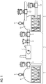
- FIG 1 a simplified excerpt of a process engineering system for the storage and distribution of gas is shown.
- the system is divided into three subsystems 1, 2, 3.
- the first subsystem 1 has a first pressure chamber 4 and a first drain valve 5 connected to it.
- the first pressure chamber 4 has a first pressure sensor 6.
- the second subsystem comprises a compressor 7, which is connected to an inlet valve 9 via a first flow sensor 8.
- the third subsystem 3 has a second pressure chamber 10 connected to the inlet valve 9.
- the second pressure chamber 10 has a second pressure sensor 11 and is connected to a second discharge valve 12 and a third discharge valve 13.
- All the technical objects 4-13 of the system shown are automated by various process objects of a control system that controls the system.
- the compressor 7 can be assigned a process object “engine control”, the inlet valve 9 a process object “inlet valve control” etc.
- the technical objects 4-6 of the first subsystem 1 as well as the technical objects 7-13 of the second and third subsystem 2, 3 are each located on a "procedural line", i.e. they are directly dependent on one another or have operative connections with one another.
- the invention is based on the object of specifying a device for operating and monitoring a process plant that makes it faster and more efficient to find alarm causes and alarm dependencies between different process objects of a process plant - without the need for additional analysis tools such as message sequence displays.
- An operator station server according to the invention of a control system of a process engineering plant has a computer-implemented process image, the computer-implemented process image at a runtime of the process engineering system including at least a first computer-implemented process object and a second computer-implemented process object, each of which is assigned to a technical object of the process engineering system and with are in operative connection with this, the two assigned technical objects being in operative connection within the process-engineering plant.
- the operator station server is characterized in that the first process object has a reference to the second process object.
- the process engineering plant can be a plant from the process industry such as a chemical, pharmaceutical, petrochemical or a plant from the food and beverage industry.
- control system each have a control system or at least one computer-aided module for controlling and regulating the ongoing process or production.
- a control system is understood to be a computer-aided technical system that includes functionalities for displaying, operating and managing a technical system such as a production facility.
- the control system includes sensors for determining measured values and various actuators.
- the control system includes so-called process or production-related components that are used to control the actuators or sensors.
- the control system shows, among other things Means for visualizing the technical system and for engineering.
- control system also includes further processing units for more complex regulations and systems for data storage and processing.
- a technical object can be individual sensors or actuators of the process engineering system.
- a technical object can also be a combination of several sensors and / or actuators, for example a motor, a reactor, a pump or a valve system.
- an "operator station server” is understood to mean a server that centrally records data from an operator control and monitoring system and, as a rule, alarm and measured value archives of a process control system of a process plant and makes it available to users.
- the operator station server usually establishes a communication link to the automation systems of the process plant and forwards data from the process plant to so-called operator station clients, which are used to operate and monitor the operation of the individual functional elements of the process plant.
- operator station server can, without being limited to this, be a SIMATIC PCS 7 industrial workstation server from SIEMENS.
- the operator station server has a process image, i.e. A current status of the technical objects of the process engineering plant is stored on the server at the runtime of the plant.
- the process image comprises at least a first computer-implemented process object and a second computer-implemented process object.
- the (first and second) process objects in the process image of the operator station server references are expanded in order to be able to relationally relate the different process objects of the process engineering system to a mapping of a process engineering line of the system.
- the reference is a structured and direction-oriented reference to another process object.
- the values of the structured reference can be derived in an engineering phase, for example from CFC plans (Continuous Functional Chart) or tabular relation matrices and integrated into the configuration of the operator station server.
- the operator station server is able to dynamically determine information on procedural strands between the individual process objects during a runtime of the procedural plant and to forward it to any downstream device for operating and monitoring.
- the operative connection between a first and a second tank can consist, for example, in the fact that a fluid can flow from the first tank into the second tank.
- the first process object preferably has further references to further process objects
- the process objects are each assigned to a technical object of the process-engineering system and are in operative connection with it, and wherein the technical objects assigned to the further process objects are in operative connection with the technical object assigned to the first process object, and the first process object is assigned information about how many references to the further process objects the first process object has.
- the operator station server can be connected to an operator station client, the operator station client being provided and designed to receive visualization information from the operator station server during a runtime of the process plant in order to at least the first and the second process object and the operative connection between the two technical objects assigned to the first and second process object in the form of symbolic system images.
- the operator station server is thus able to determine the dependency from the process objects of the symbols present in a plant picture - so to speak, to derive the process-related strand.
- the operator station server e has an operator station client, the operator station client being provided and designed to receive visualization information from the operator station server during the runtime of the process engineering system in order to at least the first and the second process object and the To visually represent active connection between the two technical objects assigned to the first and second process object in the form of symbolic system images, and the operator station client is provided and designed to provide at least one first visual representation during the runtime of the technical system, the at least one to the comprises a symbolic system image belonging to the first process object, and to generate a second visual representation which comprises at least one symbolic system image belonging to the second process object, wherein the first visual representation has a representation reference to the second visual representation, and vice versa, wherein an operator of the process engineering system can switch between a display of the two visual representations by selecting the respective representation reference.
- An operator is understood to be a human operator of the process engineering plant.
- the operator interacts with the technical system or its control system by means of special user interfaces and controls special technical functions of the system.
- the operator can use an operating and monitoring system of the control system.
- the operator can navigate along the derived procedural strand from plant picture to plant picture, for example to be able to identify the cause of a surge of alarms or the like quickly and efficiently.
- control system means that the control system, or more precisely a visualization service of the control system, is aware of information about the respective data structure types in order to be able to transfer this to a connected operator station client for graphical presentation.
- control system for a process engineering system which has at least one operator station server as explained above.
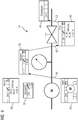
- FIG 2 a part of a control system 14 according to the invention of a technical system designed as a process engineering system is shown.
- the control system 14 comprises a first server of an operating system or an operator station server 15 and a second operator station server 16.
- the control system has an operator station client 17.
- the first operator station server 15, the second operator station server 16 and the operator station client 17 are connected to one another via a terminal bus 18 and to other components of the control system 14, not shown, such as an engineering system server or a process data archive.
- a user or operator has access to the first operator station server 15 and to the second operator station server 16 by means of the terminal bus 18 by means of the operator station client 17 in the context of operation and monitoring.
- the terminal bus 18 can, without being limited to it, be designed for example as Industrial Ethernet.
- the first operator station server 15 has a first device interface 19 which can be connected to a system bus (not shown).
- the first operator station server 15 can use this to communicate with an (external) device or an application, in particular a web application.
- the second operator station server 16 has a second device interface 20, which can also be connected to a system bus (not shown).
- the first operator station server 15 has a first computer-implemented process image 21 in which process values received at a runtime of the process engineering system are stored.
- the first operator station server 15 also includes a visualization service 23 for outputting visualization information to the operator station client 17.
- the process values are assigned to different computer-implemented process objects 22a, 22b, 22c.
- the computer-implemented process objects 22a, 22b, 22c are each assigned to a technical object of the process engineering system and are accordingly in an operative connection with them. This means that, for example, sensor values that arise in the associated technical object are mapped in the associated process object 22a, 22b, 22c.
- the process objects 22a, 22b, 22c are in FIG 2 with the designations "POI: Mot1", “POI: MonAn1" and "POI: PID1".
- Each process object 22a, 22b, 22c has a number of assigned parameters which are shown in FIG 2 are designated with "AlarmStatus", “PV_Out”, "SP_Out” etc.
- the visualization service 23 generates (among other things) a symbolic plant image 27 from the information stored in the process image 21, which is transmitted to the operator station client 17 for visualization.
- a first software component 26 of the visualization service 23 uses the references 24a, 24b, 24c to determine a dependency on block symbols generated from the process objects 22a, 22b, 22c in the symbolic system image 27 - in order to derive the procedural strand for the system image, so to speak.
- a second software component 28 of the visualization service 23 (a so-called “Screen Object Model” or SOM for short) is used to generate the block symbols for the process objects 22a, 22b, 22c for display in the system image 27.
- the first software component 26 calculates the entire procedural strand, i.e. Process objects 22a, 22b, 22c are also included in the calculation of the line, of which no block symbols are displayed in the currently displayed system image 27. If the procedural line contains process objects 22a, 22b, 22c whose block symbols are not present in the current system image 27, the system images 27 are determined for those process objects 22a, 22b, 22c in which they are present.
- group alarms are calculated and updated for the process objects 22a, 22b, 22c concerned (that is, their block symbols are shown in the respective system image 27).
- "screen change buttons” can then be dynamically created in the currently open system image 27 at runtime in order to be able to navigate along the derived procedural strand from system image 27 to system image 27. In the FIG 3-7 this aspect is illustrated even more clearly.
- the second operator station server 16 analogously to the first operator station server 15, has a second computer-implemented process image 30 in which process values received during a runtime of the process engineering system are stored.
- the second operator station server 16 also includes a visualization service 29 for outputting visualization information to the operator station client 17.
- the process values are assigned to various computer-implemented process objects 31a, 31b, 31c.
- the computer-implemented process objects 31a, 31b, 31c are each assigned to a technical object of the process engineering system and are accordingly in an operative connection with them.
- the process objects 31a, 31b, 31c are in FIG 2 with the designations "POI: MonAn2", “POI: PID2" and "POI: PID3".
- Each process object 31a, 31b, 31c has a number of assigned parameters which are shown in FIG 2 are designated with "AlarmStatus", "PV_Out", "SP_Out” etc.
- Each process object 31a, 31b, 31c has a structured and direction-oriented reference 32a, 32b, 32c, which is shown in FIG FIG 2 is designated with "Dependency Tag Struct" (the dependency is marked with double arrows 33a, 33b, 24c).
- the references 24a, 24b, 24c, 32a, 32b, 32c can also refer to process objects 22a, 22b, 22c, 31a, 31b, 31c that are in a process image 21, 30 of another operator station server 15, 16 are stored.
- the visualization service 29 of the second operator station server 16 has a first software component 34 and a second software component 35.
- FIG. 3 is an exemplary system image 27 of the first subsystem 1 and the second subsystem 2 FIG 1 with block symbols 36-40, which refer to the technical objects of the first subsystem 1 and the second subsystem 2 FIG 1 Respectively.
- a first block symbol 36 corresponds to the first discharge valve 5
- a second block symbol 37 corresponds to the first pressure sensor 6
- a third block symbol 38 corresponds to the flow sensor 8
- a fourth block symbol 39 corresponds to the compressor 7
- a fifth block symbol 40 corresponds to the Inlet valve 9.
- M the compressor 7
- the flow sensor 8 (“arrow")
- valve inlet valve 9
- the dependency determined by the first software component 26 ("DCS Domain Logic") between the technical objects on which the block symbols 36-40 are based was used dynamically by means of the second software component 27 of the first operator station server 15 to expand the system image 27 by means of the to identify the procedural line on which the selected block symbol is based.
- the procedural data flow was visualized by directed arrows 41, 42, 43 - the color of the arrow (not visible here) corresponds to the alarm class color of the highest-priority alarm along the procedural strand. Since the procedural line is located in a further plant diagram 45 (cf. FIG 5 and 6) continued, a display reference 44 (a so-called “picture change button”, labeled “subsystem 3”) was also inserted.
- the display reference 44 contains a list of the alarms of the process objects whose block symbols 46, 47, 48 are located in the further system image 45.
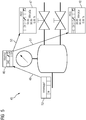
- FIG 5 is an exemplary further system image 45 of the third subsystem 3 from FIG 1 with block symbols 46, 47, 48, which relate to the technical objects of the third subsystem 3 FIG 1 Respectively.
- a first block symbol 46 corresponds to the second pressure sensor 11
- a second block symbol 47 corresponds to the second discharge valve 12
- a third block symbol 48 corresponds to the third discharge valve 13.
- FIG 5 Analogous to FIG 4 is also in FIG 5 the previously determined procedural data flow by directional arrows 49, 50, 51 visualized.
- the system image shows 45 FIG 5 a display reference 52 (“subsystem 2”), which enables a change to the system image 27, and a listing of the alarms of the process objects whose block symbols 38-40 are in the system image 27 according to FIG 4 are located.
- the operator can also directly select the alarm status in the representation references 44, 52.
- the operator can also deactivate the representation of the procedural strand in the system images 27, 45.
Landscapes
- Engineering & Computer Science (AREA)
- Physics & Mathematics (AREA)
- General Physics & Mathematics (AREA)
- Automation & Control Theory (AREA)
- General Engineering & Computer Science (AREA)
- Manufacturing & Machinery (AREA)
- Quality & Reliability (AREA)
- Testing And Monitoring For Control Systems (AREA)
Priority Applications (5)
| Application Number | Priority Date | Filing Date | Title |
|---|---|---|---|
| EP19173091.0A EP3736647A1 (fr) | 2019-05-07 | 2019-05-07 | Dépendances entre des objets de processus |
| PCT/EP2020/062604 WO2020225316A1 (fr) | 2019-05-07 | 2020-05-06 | Dépendances entre des objets de processus |
| CN202080034087.8A CN113811823B (zh) | 2019-05-07 | 2020-05-06 | 过程对象之间的相关性 |
| EP20728679.0A EP3953774B1 (fr) | 2019-05-07 | 2020-05-06 | Dispositif pour la détection de causes d'alarmes |
| US17/608,920 US12147219B2 (en) | 2019-05-07 | 2020-05-06 | Control system and operator server for establishing dependencies between process objects |
Applications Claiming Priority (1)
| Application Number | Priority Date | Filing Date | Title |
|---|---|---|---|
| EP19173091.0A EP3736647A1 (fr) | 2019-05-07 | 2019-05-07 | Dépendances entre des objets de processus |
Publications (1)
| Publication Number | Publication Date |
|---|---|
| EP3736647A1 true EP3736647A1 (fr) | 2020-11-11 |
Family
ID=66668674
Family Applications (2)
| Application Number | Title | Priority Date | Filing Date |
|---|---|---|---|
| EP19173091.0A Withdrawn EP3736647A1 (fr) | 2019-05-07 | 2019-05-07 | Dépendances entre des objets de processus |
| EP20728679.0A Active EP3953774B1 (fr) | 2019-05-07 | 2020-05-06 | Dispositif pour la détection de causes d'alarmes |
Family Applications After (1)
| Application Number | Title | Priority Date | Filing Date |
|---|---|---|---|
| EP20728679.0A Active EP3953774B1 (fr) | 2019-05-07 | 2020-05-06 | Dispositif pour la détection de causes d'alarmes |
Country Status (4)
| Country | Link |
|---|---|
| US (1) | US12147219B2 (fr) |
| EP (2) | EP3736647A1 (fr) |
| CN (1) | CN113811823B (fr) |
| WO (1) | WO2020225316A1 (fr) |
Cited By (6)
| Publication number | Priority date | Publication date | Assignee | Title |
|---|---|---|---|---|
| EP3964905A1 (fr) * | 2020-09-04 | 2022-03-09 | Siemens Aktiengesellschaft | Dépendances spécifiques à l'utilisateur entre les représentations numériques d'objets de processus |
| EP4030252A1 (fr) * | 2021-01-18 | 2022-07-20 | Siemens Aktiengesellschaft | Gestion de la charge lors de l'affichage d'un indicateur de message d'alarme |
| EP4141594A1 (fr) | 2021-08-23 | 2023-03-01 | Siemens Aktiengesellschaft | Réglage à granularité fine des archives locales dans des scénarios maître/maître des serveurs d'une installation technique |
| EP4163746A1 (fr) | 2021-10-05 | 2023-04-12 | Siemens Aktiengesellschaft | Système de commande pour une installation technique à des vues réduites des images de l'installation |
| EP4163741A1 (fr) | 2021-10-05 | 2023-04-12 | Siemens Aktiengesellschaft | Moyens contextualisés et collaboratifs de sécurité d'affichage d'un système de commande pour une installation technique |
| EP4478137A1 (fr) * | 2023-06-12 | 2024-12-18 | Siemens Aktiengesellschaft | Système de guidage pour une installation technique |
Citations (2)
| Publication number | Priority date | Publication date | Assignee | Title |
|---|---|---|---|---|
| EP3151217A1 (fr) * | 2015-10-02 | 2017-04-05 | Siemens Aktiengesellschaft | Systeme d'apprentissage pour operateur |
| EP3361341A1 (fr) * | 2017-02-13 | 2018-08-15 | Siemens Aktiengesellschaft | Procédé de surveillance des états d'appareils d'un système d'automatisation et système opérateur |
Family Cites Families (18)
| Publication number | Priority date | Publication date | Assignee | Title |
|---|---|---|---|---|
| JP2007536634A (ja) * | 2004-05-04 | 2007-12-13 | フィッシャー−ローズマウント・システムズ・インコーポレーテッド | プロセス制御システムのためのサービス指向型アーキテクチャ |
| CA2676441C (fr) * | 2006-02-03 | 2015-11-24 | Recherche 2000 Inc. | Procede et systeme de controle intelligent pour construire des modeles predictifs et detecter des anomalies |
| US8108790B2 (en) * | 2007-03-26 | 2012-01-31 | Honeywell International Inc. | Apparatus and method for visualization of control techniques in a process control system |
| US20090282067A1 (en) * | 2008-02-25 | 2009-11-12 | Invensys Systems, Inc. | System and method for generating control system database and graphics from schema-based intermediate descriptions |
| EP2360542A1 (fr) * | 2010-02-22 | 2011-08-24 | Siemens Aktiengesellschaft | Procédé de projection d'une image de processus pouvant être présentée sur un appareil de commande et d'observation |
| DE102010019142A1 (de) * | 2010-05-03 | 2011-11-03 | Siemens Aktiengesellschaft | Makromanagementsystem für ein Engineeringsystem zur Parametrierung von Schaltgeräten |
| WO2012163404A1 (fr) * | 2011-05-30 | 2012-12-06 | Abb Research Ltd | Utilisation d'architecture unifiée (ua) pour commande de protocole ole (opc) afin de générer automatiquement des graphismes de processus |
| CN107678412B (zh) | 2012-10-08 | 2020-05-15 | 费希尔-罗斯蒙特系统公司 | 用利用覆盖的派生和链接的定义配置图形元素对象的方法 |
| US9977413B2 (en) * | 2013-03-11 | 2018-05-22 | Honeywell International Inc. | Apparatus and method for managing open windows in a graphical display for a representation of a process system |
| WO2016051303A1 (fr) * | 2014-10-01 | 2016-04-07 | Abb Technology Ltd. | Procédé et système pour configurer des dispositifs d'un système de commande sur la base d'objets graphiques d'ingénierie |
| EP3067768B1 (fr) * | 2015-03-11 | 2018-04-25 | Siemens Aktiengesellschaft | Dispositif d'automatisation et système opérateur |
| EP3082001B1 (fr) * | 2015-04-13 | 2020-09-09 | Siemens Aktiengesellschaft | Procédé d'extension d'un dispositif d'automatisation avec un virtuel appareil d'automatisation et dispositif d'automatisation |
| CN108351626B (zh) * | 2015-11-02 | 2020-12-04 | Abb瑞士股份有限公司 | 用于自动化系统配置的系统和方法 |
| EP3264208B1 (fr) * | 2016-06-30 | 2021-01-06 | Siemens Aktiengesellschaft | Procede d'actualisation d'objets de processus dans un systeme d'ingenierie |
| EP3279755B1 (fr) * | 2016-08-02 | 2021-09-29 | ABB Schweiz AG | Procédé de surveillance d'une installation de traitement modulaire complexe avec une pluralité de modules de traitement interconnectés |
| EP3396479B1 (fr) * | 2017-04-28 | 2020-03-18 | Siemens Aktiengesellschaft | Système d'ingénierie |
| EP3495903B1 (fr) * | 2017-12-05 | 2020-02-26 | Siemens Aktiengesellschaft | Procédé de commande et de surveillance d'une installation technique à commander ainsi que système d'exploitation |
| US11501036B2 (en) * | 2018-03-28 | 2022-11-15 | Abb Schweiz Ag | Simulations in a model of a process control system |
-
2019
- 2019-05-07 EP EP19173091.0A patent/EP3736647A1/fr not_active Withdrawn
-
2020
- 2020-05-06 EP EP20728679.0A patent/EP3953774B1/fr active Active
- 2020-05-06 US US17/608,920 patent/US12147219B2/en active Active
- 2020-05-06 WO PCT/EP2020/062604 patent/WO2020225316A1/fr not_active Ceased
- 2020-05-06 CN CN202080034087.8A patent/CN113811823B/zh active Active
Patent Citations (2)
| Publication number | Priority date | Publication date | Assignee | Title |
|---|---|---|---|---|
| EP3151217A1 (fr) * | 2015-10-02 | 2017-04-05 | Siemens Aktiengesellschaft | Systeme d'apprentissage pour operateur |
| EP3361341A1 (fr) * | 2017-02-13 | 2018-08-15 | Siemens Aktiengesellschaft | Procédé de surveillance des états d'appareils d'un système d'automatisation et système opérateur |
Cited By (10)
| Publication number | Priority date | Publication date | Assignee | Title |
|---|---|---|---|---|
| EP3964905A1 (fr) * | 2020-09-04 | 2022-03-09 | Siemens Aktiengesellschaft | Dépendances spécifiques à l'utilisateur entre les représentations numériques d'objets de processus |
| EP4030252A1 (fr) * | 2021-01-18 | 2022-07-20 | Siemens Aktiengesellschaft | Gestion de la charge lors de l'affichage d'un indicateur de message d'alarme |
| US11841701B2 (en) | 2021-01-18 | 2023-12-12 | Siemens Aktiengesellschaft | Load management for displaying an alarm signal indicator |
| EP4141594A1 (fr) | 2021-08-23 | 2023-03-01 | Siemens Aktiengesellschaft | Réglage à granularité fine des archives locales dans des scénarios maître/maître des serveurs d'une installation technique |
| US11625350B2 (en) | 2021-08-23 | 2023-04-11 | Siemens Aktiengesellschaft | Control system and method for fine-grained reconciliation of local archives in master/master scenarios of servers of a technical installation |
| EP4163746A1 (fr) | 2021-10-05 | 2023-04-12 | Siemens Aktiengesellschaft | Système de commande pour une installation technique à des vues réduites des images de l'installation |
| EP4163741A1 (fr) | 2021-10-05 | 2023-04-12 | Siemens Aktiengesellschaft | Moyens contextualisés et collaboratifs de sécurité d'affichage d'un système de commande pour une installation technique |
| WO2023057365A1 (fr) | 2021-10-05 | 2023-04-13 | Siemens Aktiengesellschaft | Système de guidage pour une installation technique avec des vues réduites d'images de l'installation |
| WO2023057364A1 (fr) | 2021-10-05 | 2023-04-13 | Siemens Aktiengesellschaft | Création contextualisée et collaborative de sauvegardes d'écrans dans un système de commande pour une installation technique |
| EP4478137A1 (fr) * | 2023-06-12 | 2024-12-18 | Siemens Aktiengesellschaft | Système de guidage pour une installation technique |
Also Published As
| Publication number | Publication date |
|---|---|
| WO2020225316A1 (fr) | 2020-11-12 |
| US12147219B2 (en) | 2024-11-19 |
| EP3953774B1 (fr) | 2023-03-01 |
| EP3953774A1 (fr) | 2022-02-16 |
| CN113811823A (zh) | 2021-12-17 |
| CN113811823B (zh) | 2024-12-10 |
| US20220197257A1 (en) | 2022-06-23 |
Similar Documents
| Publication | Publication Date | Title |
|---|---|---|
| EP3953774B1 (fr) | Dispositif pour la détection de causes d'alarmes | |
| DE10154534B4 (de) | Integrierte Alarmanzeige in einem Prozeßsteuerungsnetzwerk | |
| DE102010017273B4 (de) | Verfahren und Vorrrichtung zur Voraussage einer Prozessqualität in einem Prozesssteuerungssystem | |
| EP3623891A1 (fr) | Hiérarchies d'images pouvant être individualisées pour un système de conduite d'une installation technique | |
| EP3538962B1 (fr) | Procédé d'analyse de dysfonctionnements dans une installation de l'automatisation de processus | |
| WO2020144305A1 (fr) | Entrée de boucle d'alarme d'affichages de séquences de message | |
| EP3805882A1 (fr) | Système de guidage pour une installation technique pourvu de diagramme de courbe de tendance | |
| EP4083731A1 (fr) | Gestion des alarmes dans des installations de processus | |
| WO2021094482A1 (fr) | Système de guidage pour une installation technique à diagramme de courbe de tendance à codage visuel | |
| EP4099114B1 (fr) | Procédé de détection d'une commande restreinte et d'observation d'une installation technique, système de commande et d'observation et système de contrôle de processus | |
| WO2022238496A1 (fr) | Système de commande pour une installation technique | |
| EP4295203A1 (fr) | Système de commande pour une installation technique faisant appel à un diagramme de courbe de tendance | |
| EP4261629A1 (fr) | Système de commande pour une installation technique et procédé de fonctionnement | |
| EP4341759B1 (fr) | Conteneur associé à une alarme dans les photos d'installation des installations techniques | |
| EP4290326A1 (fr) | Système de commande pour une installation technique et procédé de fonctionnement | |
| EP4332699B1 (fr) | Système de guidage assisté d'opérateur pour une installation technique et procédé de fonctionnement | |
| EP4354233A1 (fr) | Système de guidage pour une installation technique et procédé de fonctionnement | |
| EP4030252B1 (fr) | Gestion de la charge lors de l'affichage d'un indicateur de message d'alarme | |
| EP4485099B1 (fr) | Système de guidage pour une installation technique et procédé de fonctionnement | |
| EP4449220B1 (fr) | Système de commande pour une installation technique et procédé de fonctionnement | |
| EP4462200A1 (fr) | Fragments d'images d'installations pour la commande et l'observation | |
| WO2025176445A1 (fr) | Affichage de courbes de tendance critiques pendant le fonctionnement et l'observation | |
| WO2026021795A1 (fr) | Gestion d'alarme intégrale pour un système de commande d'une installation technique | |
| WO2023222384A1 (fr) | Système de commande pour une installation technique, et procédé de fonctionnement | |
| EP4700515A1 (fr) | Recherche d'équivalence dans des diagrammes de séquence d'un système de guidage d'une installation technique |
Legal Events
| Date | Code | Title | Description |
|---|---|---|---|
| PUAI | Public reference made under article 153(3) epc to a published international application that has entered the european phase |
Free format text: ORIGINAL CODE: 0009012 |
|
| STAA | Information on the status of an ep patent application or granted ep patent |
Free format text: STATUS: THE APPLICATION HAS BEEN PUBLISHED |
|
| AK | Designated contracting states |
Kind code of ref document: A1 Designated state(s): AL AT BE BG CH CY CZ DE DK EE ES FI FR GB GR HR HU IE IS IT LI LT LU LV MC MK MT NL NO PL PT RO RS SE SI SK SM TR |
|
| AX | Request for extension of the european patent |
Extension state: BA ME |
|
| STAA | Information on the status of an ep patent application or granted ep patent |
Free format text: STATUS: THE APPLICATION IS DEEMED TO BE WITHDRAWN |
|
| 18D | Application deemed to be withdrawn |
Effective date: 20210512 |