EP3736727A1 - Module d'écran et dispositif électronique équipé de celui-ci - Google Patents
Module d'écran et dispositif électronique équipé de celui-ci Download PDFInfo
- Publication number
- EP3736727A1 EP3736727A1 EP18903576.9A EP18903576A EP3736727A1 EP 3736727 A1 EP3736727 A1 EP 3736727A1 EP 18903576 A EP18903576 A EP 18903576A EP 3736727 A1 EP3736727 A1 EP 3736727A1
- Authority
- EP
- European Patent Office
- Prior art keywords
- light
- aperture
- imaging unit
- screen module
- reflection layer
- Prior art date
- Legal status (The legal status is an assumption and is not a legal conclusion. Google has not performed a legal analysis and makes no representation as to the accuracy of the status listed.)
- Granted
Links
Images


Classifications
-
- G—PHYSICS
- G06—COMPUTING OR CALCULATING; COUNTING
- G06F—ELECTRIC DIGITAL DATA PROCESSING
- G06F3/00—Input arrangements for transferring data to be processed into a form capable of being handled by the computer; Output arrangements for transferring data from processing unit to output unit, e.g. interface arrangements
- G06F3/01—Input arrangements or combined input and output arrangements for interaction between user and computer
- G06F3/03—Arrangements for converting the position or the displacement of a member into a coded form
- G06F3/041—Digitisers, e.g. for touch screens or touch pads, characterised by the transducing means
- G06F3/042—Digitisers, e.g. for touch screens or touch pads, characterised by the transducing means by opto-electronic means
- G06F3/0421—Digitisers, e.g. for touch screens or touch pads, characterised by the transducing means by opto-electronic means by interrupting or reflecting a light beam, e.g. optical touch-screen
-
- G—PHYSICS
- G06—COMPUTING OR CALCULATING; COUNTING
- G06F—ELECTRIC DIGITAL DATA PROCESSING
- G06F1/00—Details not covered by groups G06F3/00 - G06F13/00 and G06F21/00
- G06F1/16—Constructional details or arrangements
-
- G—PHYSICS
- G06—COMPUTING OR CALCULATING; COUNTING
- G06F—ELECTRIC DIGITAL DATA PROCESSING
- G06F1/00—Details not covered by groups G06F3/00 - G06F13/00 and G06F21/00
- G06F1/16—Constructional details or arrangements
- G06F1/1613—Constructional details or arrangements for portable computers
- G06F1/1633—Constructional details or arrangements of portable computers not specific to the type of enclosures covered by groups G06F1/1615 - G06F1/1626
- G06F1/1637—Details related to the display arrangement, including those related to the mounting of the display in the housing
-
- G—PHYSICS
- G06—COMPUTING OR CALCULATING; COUNTING
- G06V—IMAGE OR VIDEO RECOGNITION OR UNDERSTANDING
- G06V40/00—Recognition of biometric, human-related or animal-related patterns in image or video data
- G06V40/10—Human or animal bodies, e.g. vehicle occupants or pedestrians; Body parts, e.g. hands
- G06V40/12—Fingerprints or palmprints
- G06V40/13—Sensors therefor
- G06V40/1318—Sensors therefor using electro-optical elements or layers, e.g. electroluminescent sensing
-
- G—PHYSICS
- G09—EDUCATION; CRYPTOGRAPHY; DISPLAY; ADVERTISING; SEALS
- G09F—DISPLAYING; ADVERTISING; SIGNS; LABELS OR NAME-PLATES; SEALS
- G09F9/00—Indicating arrangements for variable information in which the information is built-up on a support by selection or combination of individual elements
-
- H—ELECTRICITY
- H04—ELECTRIC COMMUNICATION TECHNIQUE
- H04M—TELEPHONIC COMMUNICATION
- H04M1/00—Substation equipment, e.g. for use by subscribers
- H04M1/02—Constructional features of telephone sets
- H04M1/0202—Portable telephone sets, e.g. cordless phones, mobile phones or bar type handsets
- H04M1/026—Details of the structure or mounting of specific components
-
- H—ELECTRICITY
- H10—SEMICONDUCTOR DEVICES; ELECTRIC SOLID-STATE DEVICES NOT OTHERWISE PROVIDED FOR
- H10K—ORGANIC ELECTRIC SOLID-STATE DEVICES
- H10K50/00—Organic light-emitting devices
- H10K50/80—Constructional details
- H10K50/85—Arrangements for extracting light from the devices
- H10K50/856—Arrangements for extracting light from the devices comprising reflective means
-
- H—ELECTRICITY
- H10—SEMICONDUCTOR DEVICES; ELECTRIC SOLID-STATE DEVICES NOT OTHERWISE PROVIDED FOR
- H10K—ORGANIC ELECTRIC SOLID-STATE DEVICES
- H10K50/00—Organic light-emitting devices
- H10K50/80—Constructional details
- H10K50/86—Arrangements for improving contrast, e.g. preventing reflection of ambient light
- H10K50/865—Arrangements for improving contrast, e.g. preventing reflection of ambient light comprising light absorbing layers, e.g. light-blocking layers
-
- H—ELECTRICITY
- H10—SEMICONDUCTOR DEVICES; ELECTRIC SOLID-STATE DEVICES NOT OTHERWISE PROVIDED FOR
- H10K—ORGANIC ELECTRIC SOLID-STATE DEVICES
- H10K59/00—Integrated devices, or assemblies of multiple devices, comprising at least one organic light-emitting element covered by group H10K50/00
- H10K59/60—OLEDs integrated with inorganic light-sensitive elements, e.g. with inorganic solar cells or inorganic photodiodes
- H10K59/65—OLEDs integrated with inorganic image sensors
Definitions
- This application relates to the computer field, and in particular, to a screen module and an electronic device provided with a screen module.
- the fingerprint sensor is usually disposed at a lower part of a front panel of the terminal device or on the back of the terminal device, having a disadvantage of occupying display screen space or being inconvenient to use. Therefore, how to dispose the fingerprint sensor at a lower layer of a touchscreen is an important subject in the art.
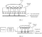
- a display screen including an external screen, a light emitting board, and an optical-to-electrical conversion unit.
- the light emitting board has light emitting units and a circuit network connecting the light emitting units to each other. Light emitted by the light emitting units is projected to the external screen.
- the circuit network separates the light emitting board into a plurality of gaps.
- Alight blocking layer is disposed below the light emitting board, and the light blocking layer has a light transmission hole. The gaps and the light transmission hole form a light path.
- the light emitted by the light emitting units is reflected by an object (such as a finger) on or outside the external screen, and then irradiates the optical-to-electrical conversion unit after passing through the light path, thereby implementing an image acquisition function.
- the display screen is relatively thick, and a terminal device provided with the display screen is also relatively thick, causing inconvenience in holding.
- this application provides a screen module, to collect an image by using a light reflection structure in the screen module, thereby reducing a thickness of a display screen and improving use convenience of a user.
- a screen module including: an external screen, a first light blocking layer, a substrate, and a reflection layer that are disposed from outside to inside.
- An imaging unit array is disposed on the substrate, the imaging unit array includes a plurality of imaging units, and a photosensitive surface of the imaging unit is opposite to the reflection layer.
- the first light blocking layer is provided with a first aperture array, the first aperture array includes a plurality of first apertures, and the first aperture is used to allow light reflected by an object outside the external screen to the reflection layer to pass through.
- the reflection layer is configured to reflect, to the imaging unit, the light passing through the first aperture.
- the screen module in this application is thinner, so that a terminal device is thinner and easier to hold.
- the screen module further includes a light emitting pixel array disposed on the substrate, and the light emitting pixel array includes a plurality of light emitting pixels; and the first light blocking layer is further provided with a second aperture array, the second aperture array includes a plurality of second apertures, and each second aperture is provided in correspondence to the light emitting pixel, and is used to allow light emitted by the light emitting pixel to the external screen to pass through.
- light emitting of the light emitting pixel array may be controlled by using a display control circuit.
- the light produced by the light emitting pixel array is more stable than ambient light. When the light of the light emitting pixel array irradiates the object outside the external screen, the object can scatter more light, so that the imaging unit can receive more light, thereby achieving a better imaging effect.
- a second light blocking layer is disposed between the substrate and the reflection layer, the second light blocking layer includes a light transmission area array, each light transmission area in the light transmission area array includes a third aperture and a fourth aperture; the third aperture is aligned with the first aperture, and the third aperture is used to allow the light passing through the first aperture to pass through; and the fourth aperture is used to allow the light reflected by the reflection layer to the imaging unit to pass through.
- the second light blocking layer may block a part of light entering the substrate from the reflection layer, to prevent the light reflected by the reflection layer from irradiating a top-gate structure of a TFT substrate, thereby avoiding abnormal light emission caused by reflected light.
- an isolation layer is disposed between the reflection layer and the substrate, and grid boxes of the isolation layer are in a one-to-one correspondence with the imaging units; and the grid boxes are made of an opaque material and are configured to isolate light received by the different imaging units. In this way, crosstalk of the light reflected by the reflection layer to the imaging unit can be prevented, thereby resolving a problem of unclear imaging caused by the crosstalk of the light.
- a transparent polymer is filled inside each grid box.
- the transparent polymer may be used as a support, so that the isolation layer can fit the substrate.
- a ratio of a distance from the first light blocking layer to the external screen to a distance from the second light blocking layer to the reflection layer ranges from 1 to 40. According to this implementation, a better imaging effect can be achieved.
- a density of the imaging unit on the substrate is greater than 200 pore density PPI.
- a screen module including: an external screen, a first light blocking layer, a substrate, a second light blocking layer, and a reflection layer that are disposed from outside to inside.
- An imaging unit array is disposed on an outer surface of the substrate, the imaging unit array includes a plurality of imaging units, and a photosensitive surface of the imaging unit is opposite to the reflection layer.
- a surface of the first light blocking layer has a light blocking area including a lightproof material, and the light blocking area is used to block light emitted from the outside to the imaging unit.
- the second light blocking layer is disposed between the substrate and the reflection layer, the second light blocking layer includes a light transmission area array, each light transmission area in the light transmission area array includes a first aperture and a second aperture, the first aperture is used to allow light reflected by an object outside the external screen to the reflection layer to pass through, and the second aperture is used to allow light reflected by the reflection layer to the imaging unit to pass through.
- the reflection layer is configured to reflect, to the imaging unit, the light passing through the first aperture.
- an aperture in the second light blocking layer is used as a hole for aperture imaging, the light from the object is reflected by the reflection layer, and imaging is performed on the imaging unit array, so that space required for the imaging can be reduced, thereby implementing short-distance imaging. Therefore, the screen module in this application is thinner, so that a terminal device is thinner and easier to hold.
- the screen module further includes a light emitting pixel array disposed on the substrate, and the light emitting pixel array includes a plurality of light emitting pixels.
- the object can scatter more light, so that the imaging unit can receive more light, thereby achieving a better imaging effect.
- an isolation layer is disposed between the reflection layer and the second light blocking layer, and grid boxes of the isolation layer are in a one-to-one correspondence with light transmission areas; and the grid boxes are made of an opaque material and are configured to isolate light received by the different imaging units. In this way, crosstalk of the light reflected by the reflection layer to the imaging unit can be prevented, thereby resolving a problem of unclear imaging caused by the crosstalk of the light.
- a ratio of a distance from the first light blocking layer to the external screen to a distance from the second light blocking layer to the reflection layer ranges from 1 to 40.
- an electronic device includes the screen module according to the first aspect or the possible implementations of the first aspect.
- an electronic device includes the screen module according to the second aspect or the possible implementations of the second aspect.
- the screen module in this application includes the external screen, the first light blocking layer, the substrate, and the reflection layer that are disposed from outside to inside.
- the imaging unit array is disposed on the substrate, and the photosensitive surface of the imaging unit is opposite to the reflection layer.
- the first light blocking layer is provided with a first aperture array, the first aperture array includes the plurality of first apertures, and the first aperture is used to allow the light reflected by the object outside the screen to the reflection layer to pass through.
- the reflection layer is configured to reflect, to the imaging unit, the light passing through the first aperture.
- the screen module in this application is thinner, so that a thickness of the terminal device is reduced, and the terminal device is easier to hold.
- a screen module provided in this application may be applied to various devices having a display function, and may specifically be a computer device, and more specifically, may be a terminal device, for example, a mobile phone, a tablet computer, a wearable device, a vehicle-mounted computer, or a self-service terminal.
- FIG. 2 is a schematic diagram of an imaging principle according to this application.
- a terminal device includes a processor, an imaging control circuit, and a screen module.
- the screen module includes an external screen, a substrate, and a reflection layer.
- An imaging unit array is integrated into the substrate.
- the imaging unit array is connected to the imaging control circuit.
- the imaging control circuit may be integrated into the substrate of the screen module, or may be disposed on a mainboard.
- the imaging control circuit obtains an image signal collected by the imaging unit array, and transmits the image signal to the processor, for example, a central processing unit (Central Processing Unit, CPU).
- the processor can implement functions such as fingerprint recognition, gesture recognition, ambient light detection, and distance detection based on a user requirement.
- an embodiment of a screen module provided in this application includes an external screen 1, a first light blocking layer 2, a substrate 3, and a reflection layer 4 that are disposed from outside to inside.
- the external screen 1 is made of a light transmission material, for example, resin or glass.
- the external screen 1 is a screen layer located at an outermost layer, for example, a touchscreen or a protective screen.
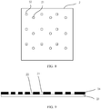
- FIG. 4 is a top view of the first light blocking layer 2 in FIG. 3 .
- the first light blocking layer 2 is provided with a first aperture array, the first aperture array includes a plurality of first apertures 21, and the first aperture 21 is used to allow light reflected by an object outside the external screen 1 to the reflection layer 4 to pass through.
- the shape of the first aperture may be but is not limited to a square, a circle, or a star. When the first aperture is circular, a diameter of the first aperture may be set based on an actual requirement, for example, between 2 micrometers and 30 micrometers.
- An imaging unit array is disposed on the substrate 3, the imaging unit array includes a plurality of imaging units 31, and a photosensitive surface of the imaging unit 31 is opposite to the reflection layer 4.
- the imaging unit 31 may be disposed near a lower surface of the substrate 3 (as shown in FIG. 3 ). In another implementation, the imaging unit 31 may be disposed in a gap of the substrate 3 (as shown in FIG. 6a ).
- the imaging unit 31 may be a photodetector (Photo Detector, PD), and may specifically include a silicon detector and a photosensitive material.
- a density of the imaging unit on the substrate 3 may be set based on an actual situation, for example, 200 pore density (pixels per inch, PPI), 500 PPI, or 1000 PPI.
- a higher density of the imaging unit indicates a higher resolution of a generated image.
- a density of the image unit is greater than 200 PPI
- a resolution of the generated image is greater than 200 PPI.
- a resolution of the generated image is greater than 500 PPI.
- the substrate 3 may be a thin-film transistor (Thin Film Transistor, TFT) substrate, and a material of the TFT substrate is resin or glass.
- TFT Thin Film Transistor
- a soft screen is made, a polyethylene terephthalate (Polyethylene terephthalate, PET) material may be selected to make the TFT substrate.
- PET Polyethylene terephthalate
- a glass material may be selected to make the TFT substrate.
- the reflection layer 4 is configured to reflect, to the imaging unit 31, the light passing through the first aperture 21.
- the reflection layer may be a thin metal film or a metal coating.
- each imaging unit may form a partial image of the object based on a part of the light reflected by the object, and the imaging unit array may form a high-definition image of the entire object based on partial images of the object formed by various imaging units.
- the screen module may obtain a fingerprint of the finger, to perform a fingerprint recognition function.
- the screen module may further implement functions such as gesture recognition, proximity detection, and ambient light detection.
- the screen module in this application is thinner, so that a terminal device is thinner and easier to hold.
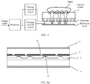
- FIG. 5 is another schematic diagram of an imaging principle according to this application.
- a terminal device includes a processor, a display control circuit, an imaging control circuit, and a screen module.
- the screen module includes an external screen, a substrate, and a reflection layer.
- a light emitting pixel array is further integrated into the substrate.
- a finger of a user performs a touch operation on the external screen, for example, pressing, touching, sliding, or gesture control.
- the screen module responds to the touch operation, and sends a trigger signal to the processor.
- the processor sends a control signal to the display control circuit based on the trigger signal, to control the light emitting pixel array in the substrate to emit light as required, for example, emit light in a specified screen area, emit light in specified luminance, or emit light for specified duration. Because the light of the light emitting pixel array is controlled by the processor, the light emitting pixel array can be used as a more stable light source.
- the reflection layer reflects, to the imaging unit array in the substrate, light from the finger, and the imaging control circuit obtains an image signal collected by the imaging unit array, and transmits the image signal to the processor.
- the processor can implement functions such as fingerprint recognition, gesture recognition, ambient light detection, and distance detection based on a user requirement.
- FIG. 6a is a schematic sectional view including an imaging unit 31
- FIG. 6b is a schematic sectional view including a light emitting pixel 32.
- FIG. 6a is a schematic transverse sectional view
- FIG. 6b is a schematic longitudinal sectional view.
- FIG. 6b is a schematic transverse sectional view.
- FIG. 6b further show an external screen 1, a first light blocking layer 2, a substrate 3, a reflection layer 4, and a first aperture 21.
- a second aperture array is further disposed on the first light blocking layer 2, and the second aperture array includes a plurality of second apertures 22.
- FIG. 7 is a top view of the substrate 3 in FIG. 6a and FIG. 6b .
- Alight emitting pixel array and an imaging unit array are disposed on the substrate 3, the imaging unit array includes a plurality of imaging units 31, the light emitting pixel array includes a plurality of light emitting pixels 32, and a photosensitive surface of the imaging unit 31 is opposite to the reflection layer 4.
- the substrate 3 may be a thin-film transistor (Thin Film Transistor, TFT) substrate, and a material of the TFT substrate is resin or glass.
- TFT Thin Film Transistor
- a soft screen is made, a polyethylene terephthalate (Polyethylene terephthalate, PET) material may be selected to make the TFT substrate.
- PET Polyethylene terephthalate
- a glass material may be selected to make the TFT substrate.
- a light emitting material is added to the TFT substrate, a light emitting pixel structure may be implemented.
- the light emitting pixel 32 may be at least one of an organic light emitting diode (Organic Light Emitting Diode, OLED), a quantum dot light emitting diode (Quantum Dot Light Emitting Diode QLED), or a micro light emitting diode microLED.
- OLED Organic Light Emitting Diode
- QLED Quantum Dot Light Emitting Diode
- microLED micro light emitting diode microLED.
- the imaging unit 31 may be a photodetector (Photo Detector, PD), and may specifically include a silicon detector and a photosensitive material.
- a density of the imaging unit on the substrate 3 may be set based on an actual situation, for example, 200 pore density (pixels per inch, PPI), 500 PPI, or 1000 PPI.
- a higher density of the imaging unit indicates a higher resolution of a generated image.
- a density of the image unit is greater than 200 PPI
- a resolution of the generated image is greater than 200 PPI.
- a density of the image unit is greater than 500 PPI
- a resolution of the generated image is greater than 500 PPI.
- a density of the light emitting pixel 32 may be the same as or different from the density of the imaging unit 31.
- a first light blocking layer 2 is provided with a first aperture array and a second aperture array.
- the second aperture array includes a plurality of second apertures 22, and each second aperture 22 is provided in correspondence to a light emitting pixel 32.
- the second aperture 22 may be provided at a position facing the light emitting pixel 32.
- the second aperture 22 is used to allow light emitted by the light emitting pixel 32 to an external screen 1 to pass through.
- FIG. 9 is a side view of the first light blocking layer 2.
- the first light blocking layer 2 includes a buffer layer 23 and a thin metal film 24 covering a surface of the buffer layer 23, and etching is performed on the thin metal film 24 to form the first aperture 21 and the second aperture 22.
- the thin metal film 24 is configured to block the light emitted by the light emitting pixel 32 to the external screen 1, to implement a light blocking function.
- the buffer layer 23 is made of a polymer material or silicon dioxide SiO 2 , and the buffer layer 23 is transparent to light. It may be understood that a light blocking material of the first light blocking layer 2 may alternatively be another lightproof material.
- the first aperture array includes a plurality of first apertures 21, and the first aperture 21 is used to allow light reflected by an object outside the external screen 1 to a reflection layer 4 to pass through. Specifically, most of light passing through each first aperture 21 is reflected to an imaging unit 31 corresponding to the first aperture 21.
- the shape of the first aperture may be but is not limited to a square, a circle, or a star. When the first aperture is circular, a diameter of the first aperture may be set based on an actual requirement, for example, between 2 micrometers and 30 micrometers.
- the reflection layer 4 is configured to reflect, to the imaging unit 31, the light passing through the first aperture 21.
- a substrate 3 may further include a display control circuit and an imaging control circuit.
- the display control circuit is electrically connected to a light emitting pixel array
- the imaging control circuit is electrically connected to an imaging unit array.
- a gap corresponding to the first aperture 21 exists between circuits of the substrate, as shown in FIG. 6a . After passing through the first aperture 21, the light reflected by the object outside the external screen 1 reaches the reflection layer 4 through the gap corresponding to the first aperture 21.
- the light emitting pixel array and the imaging unit array in this application may be at different layers, and may also be at different planes.
- the light emitted by the light emitting pixel 32 may reach the object on the surface or outside the external screen 1 through the second aperture 22.
- light emitted by the light emitting pixel array is similar to light emitted by a Lambert body, and irradiates the finger, and the finger scatters the light. A part of the light scattered by the finger passes through the first aperture 21 of the first light blocking layer 2 to reach the internal reflection layer 4, and the light reflected by the reflection layer 4 reaches the imaging unit 31.
- each imaging unit may form a partial image of the object based on a part of the light reflected by the object, and the imaging unit array may form a high-definition image of the entire object based on partial images of the object formed by various imaging units.
- the screen module may obtain a fingerprint of the finger, to perform a fingerprint recognition function.
- the screen module may further implement functions such as gesture recognition, proximity detection, and ambient light detection.
- the screen module in this application is thinner, so that the thickness of a terminal device is reduced, and the terminal device is easier to hold.
- FIG. 10a is a schematic sectional view including an imaging unit 31, and FIG. 10b is a schematic sectional view including a light emitting pixel 32.
- FIG. 10a is a schematic transverse sectional view
- FIG. 10b is a schematic longitudinal sectional view.
- FIG. 10b is a schematic transverse sectional view.
- FIG. 10a and FIG. 10b another embodiment of a screen module provided in this application includes an external screen 1, a first light blocking layer 2, a substrate 3, a reflection layer 4, and a second light blocking layer 5 that are disposed from outside to inside.
- the second light blocking layer 5 is disposed between the substrate 3 and the reflection layer 4.
- the second light blocking layer may be formed by disposing a light blocking material below a water-oxygen blocking layer of the TFT substrate.
- the light blocking material may be a thin metal film or another lightproof material.
- the second light blocking layer 5 includes a light transmission area array, and each light transmission area 51 in the light transmission area array includes a third aperture 52 and a fourth aperture 53.
- the third aperture 52 is aligned with a first aperture 21, and the third aperture 52 is used to allow light passing through the first aperture 21 to pass through.
- An aperture structure includes the first aperture 21 and the third aperture 52. Light reflected by an object outside the external screen 1 passes through the aperture structure, and is reflected by the reflection layer 4, so that aperture imaging can be implemented on the imaging unit 31.
- the fourth aperture 53 is used to allow the light reflected by the reflection layer 4 to the imaging unit 31 to pass through.
- the fourth aperture 52 is provided at a position facing the imaging unit 31.
- the light transmission area 51 is an area unit including the third aperture 52 and the fourth aperture 53 in the second light blocking layer 5, and the shape of the light transmission area 51 is not limited to a rectangle, an ellipse, or a circle.
- the shape of the third aperture 52 or the fourth aperture 53 may be but is not limited to a square, a circle, or a star.
- a diameter of the third aperture ranges from 2 micrometers to 30 micrometers.
- a side length of the third aperture ranges from 2 micrometers to 30 micrometers.
- a light emitting pixel array may alternatively not be disposed on the substrate 3 of the screen module in this application.
- the object When ambient light irradiates the object outside the external screen 1, the object may pass the light through the first aperture 21 of the first light blocking layer and the third aperture 52 of the second light blocking layer to reach the reflection layer 4. After being reflected by the reflection layer 4, the light may pass through the fourth aperture 53 of the second light blocking layer 5 to reach the imaging unit 31, and the imaging unit 31 receives the light of the object for imaging.
- light emitted by the light emitting pixel 32 may reach the object on the surface or outside the external screen 1 through the second aperture 22.
- light emitted by the light emitting pixel array is similar to light emitted by a Lambert body, and irradiates the finger, and the finger scatters the light.
- a part of the light scattered by the finger sequentially passes through the first aperture 21 of the first light blocking layer 2 and the third aperture 52 of the second light blocking layer 5 to reach the internal reflection layer 4, and the light reflected by the reflection layer 4 passes through the fourth aperture 53 to reach the imaging unit 31.
- each imaging unit 31 may form a partial image of the object based on a part of the light reflected by the object, and the imaging unit array may form a high-definition image of the entire object based on partial images of the object formed by various imaging units.
- the second light blocking layer 5 may block a part of light entering the substrate 3 from the reflection layer 4, to prevent the light reflected by the reflection layer 4 from irradiating a top-gate structure of the TFT substrate, thereby avoiding abnormal light emission caused by reflected light.
- an isolation layer is disposed between the substrate and the reflection layer, to prevent crosstalk of the light reflected by the reflection layer.
- a screen module provided in this application includes: an external screen 1, a first light blocking layer 2, a substrate 3, a reflection layer 4, and an isolation layer 6 that are disposed from outside to inside.
- the external screen 1 For specific descriptions of the external screen 1, the first light blocking layer 2, the substrate 3, and the reflection layer 4, refer to descriptions in the embodiments shown in FIG. 2 to FIG. 8 .
- the isolation layer 6 is disposed between the reflection layer 4 and the substrate 3.
- the isolation layer 6 includes a plurality of grid boxes 61, and the grid boxes 61 are in a one-to-one correspondence with the imaging units 31.
- the grid boxes 61 are made of an opaque material and are configured to isolate light received by the different imaging units 31.
- the grid boxes may be made of a rigid material, or may be made of a flexible material.
- a transparent polymer is filled inside each grid box 61.
- the grid box may be imprinted on a black opaque thin polymer film material by using an imprinting technology. A density of the grid box, a density of a light transmission area, and a density of the imaging unit are the same.
- the transparent polymer is filled inside the grid box and is solidified.
- the reflection layer 4 may be a metal film formed by depositing metal on a bottom surface of the transparent polymer.
- each imaging unit is isolated by using the grid box.
- light that enters the imaging unit from the reflection layer may be constrained, so that the reflected light does not enter an area in which the imaging unit is not located on the substrate, to prevent mutual crosstalk between light of different imaging units.
- another embodiment of a screen module provided in this application includes an external screen 1, a first light blocking layer 2, a substrate 3, a reflection layer 4, a second light blocking layer 5, and an isolation layer 6 that are disposed from outside to inside.
- an external screen 1 the first light blocking layer 2, the substrate 3, the reflection layer 4, and the second light blocking layer 5, refer to descriptions in the embodiment shown in FIG. 2 to FIG. 10 .
- the isolation layer 6 is disposed between the reflection layer 4 and the second light blocking layer 5.
- the isolation layer 6 and a grid box 61 refer to corresponding descriptions in the embodiments shown in FIG. 12 and FIG. 13 .
- each imaging unit is isolated by using the grid box.
- light that enters the imaging unit from the reflection layer may be constrained, so that the reflected light does not enter an area in which the imaging unit is not located on the substrate, to prevent mutual crosstalk between light of different imaging units.
- the object image distance ratio is a ratio of an object distance to an image distance.
- the object distance is a distance from an object to an aperture
- the image distance is a distance from an image to the aperture.
- the size of the imaging unit may be set based on an actual requirement. For example, considering that a film is attached to an external screen, causing an increase in the object image distance ratio, in this case, the size of the imaging unit needs to be designed to be smaller, to avoid overlapping of object detection areas.
- a size of aperture imaging is affected by the object image distance ratio.
- the following describes a density and the size of the imaging unit.
- a distance d1 from a first light blocking layer to an outer surface of the external screen may be used as an object distance.
- the image distance is a sum of a distance from a second aperture of a second light blocking layer and a distance from the reflection layer 4 to an imaging unit 31. Therefore, a distance d2 from the second light blocking layer to the reflection layer may be used as a half of the image distance.
- a distance from the first light blocking layer to the second light blocking layer may be designed to be several micrometers. In this way, an aperture structure includes a first aperture of the first light blocking layer and the second aperture of the second light blocking layer.
- the distance from the first light blocking layer to the outer surface of the external screen is denoted as d1.
- the distance from the second light blocking layer to the reflection layer is denoted as d2.
- a ratio of d1 to d2 usually ranges from 1 to 40, and a size of an image formed through the aperture imaging can meet an imaging requirement.
- An example in which the object image distance ratio is 10:1 the distance from the first light blocking layer to the outer surface of the external screen is 1000 micrometers ( ⁇ m), and the distance from the reflection layer to the imaging unit is 50 ⁇ m is used below.
- the resolution is 500 PPI, indicating that there are 500 imaging units per inch.
- an imaging unit array including imaging units whose sizes are less than or equal to 5.08 ⁇ m may implement the resolution of 500 PPI.
- the active area of the image unit is of a square, both a length and a width of the active area are less than or equal to 5.08 ⁇ m.
- a higher density of the imaging unit indicates a higher resolution and clearer imaging.
- the light emitting pixel array, the imaging unit array, the first aperture array, or the second aperture array shown in the accompanying drawings in this specification is an example, and is used to describe the array provided in this application, and should not be understood as a limitation on the embodiments of this application.
- another screen module provided in this application includes an external screen 161, a first light blocking layer 162, a substrate 163, a reflection layer 164, and a second light blocking layer 165 that are disposed from outside to inside.
- An imaging unit array is disposed on the substrate 163, the imaging unit array includes a plurality of imaging units 1631, and a photosensitive surface of the imaging unit 1631 is opposite to the reflection layer 164.
- the first light blocking layer 162 includes a buffer layer and a lightproof material 1621 covering a surface of the buffer layer, and a light blocking area including the lightproof material 1621 is used to block light emitted from the outside to the imaging unit 1631.
- the second light blocking layer 165 is disposed between the substrate 163 and the reflection layer 164.
- the second light blocking layer 165 includes a light transmission area array, each light transmission area 1651 in the light transmission area array includes a first aperture 1652 and a second aperture 1653, the first aperture 1652 is used to allow light reflected by an object outside the external screen to the reflection layer 164 to pass through, and the second aperture 1653 is used to allow light reflected by the reflection layer 164 to the imaging unit 1631 to pass through.
- the second aperture 1653 may be provided at a position facing the imaging unit 1631.
- the reflection layer 164 is configured to reflect, to the imaging unit 1631, the light passing through the first aperture 1652.
- the first aperture 1652 is similar to the third aperture 52 in the embodiment shown in FIG. 10a
- the second aperture 1653 is similar to the fourth aperture 53 in the embodiment shown in FIG. 10b .
- each imaging unit may form a partial image of the object based on a part of the light reflected by the object, and the imaging unit array may form a high-definition image of the entire object based on partial images of the object formed by various imaging units.
- the screen module may obtain a fingerprint of the finger, to perform a fingerprint recognition function.
- the screen module may further implement functions such as gesture recognition, proximity detection, and ambient light detection.
- the light blocking area of the first light blocking layer can block the light emitted from the outside to the imaging unit 1631.
- the screen module further includes a light emitting pixel array disposed on the substrate, and the light emitting pixel array includes a plurality of light emitting pixels.
- a light emitting pixel refer to descriptions of the light emitting pixel in the foregoing embodiments.
- an isolation layer is disposed between the reflection layer 164 and the second light blocking layer 165, and grid boxes 1801 of the isolation layer are in a one-to-one correspondence with light transmission areas 1651.
- the grid boxes 1801 are made of an opaque material and are configured to isolate light received by the different imaging units 1631.
- a transparent polymer is filled inside each grid box 1801.
- the grid box 1801 refer to a description of the grid box 61 in the foregoing embodiment.
- a ratio of a distance from the first light blocking layer 162 to the outer surface of the external screen 161 to a distance from the second light blocking layer 165 to the reflection layer 164 ranges from 1 to 40.
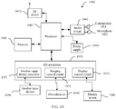
- FIG. 19 is a block diagram of a partial structure of a mobile phone 1900 related to the embodiments of this application.
- the mobile phone 1900 includes components such as a radio frequency (Radio Frequency, RF) circuit 1910, a memory 1920, another input device 1930, a display screen 1940, a photodetector 1950, an audio circuit 1960, and an input/output (Input/Output, I/O) subsystem 1970, a processor 1980, and a power supply 1990.
- RF Radio Frequency
- the mobile phone may include more or fewer components than those shown in the figure, or combine some components, or split some components, or have different component arrangements.
- the screen module provided in the embodiments of the present invention may be further applied to a terminal device besides the mobile phone, for example, a notebook computer, a wearable device, an AI device, a self-service sales terminal, or a self-service payment terminal.
- the screen module provided in the embodiments of the present invention may also be applied to another computer device besides the terminal device, for example, a server.
- the RF circuit 1910 may be configured to receive and send a signal in an information receiving and sending process or a call process.
- the RF circuit 910 sends the downlink information to the processor 1980 for processing.
- the RF circuit 910 sends related uplink data to the base station.
- the RF circuit includes but is not limited to an antenna, at least one amplifier, a transceiver, a coupler, a low noise amplifier (Low Noise Amplifier, LNA), a duplexer, and the like.
- the RF circuit 1910 may further communicate with a network and another device through wireless communication.
- Any communications standard or protocol may be used for the wireless communication, and includes but is not limited to a global system for mobile communications (Global System for Mobile communication, GSM), a general packet radio service (General Packet Radio Service, GPRS) system, a code division multiple access (Code Division Multiple Access, CDMA) system, a wideband code division multiple access (Wideband Code Division Multiple Access, WCDMA) system, a long term evolution (Long Term Evolution, LTE) system, an email, a short message service (Short Message Service, SMS), and the like.
- GSM Global System for Mobile communication
- GPRS General Packet Radio Service
- CDMA code division multiple access
- WCDMA wideband code division multiple access
- LTE Long Term Evolution
- SMS Short Message Service
- the memory 1920 may be configured to store a software program and a module.
- the processor 1980 runs the software program and the module that are stored in the memory 1920, to execute various function applications of the mobile phone 1900 and perform data processing.
- the memory 1920 may mainly include a program storage area and a data storage area.
- the program storage area may store an operating system, an application required for at least one function (such as a sound playback function or an image playback function), and the like.
- the data storage area may store data (such as audio data or a phone book) created according to use of the mobile phone 1900, and the like.
- the memory 1920 may include a high speed random access memory, and may further include a nonvolatile memory, for example, at least one magnetic disk storage device, a flash memory device, or another volatile solid-state storage device.
- the another input device 1930 may be configured to: receive input digit or character information, and generate a keyboard signal input related to user settings and function control of the mobile phone 1900.
- the another input device 1930 may include but is not limited to one or more of a physical keyboard, a function key (such as a volume control key or an on/off key), a trackball, a mouse, a joystick, an optical mouse (the optical mouse is a touch-sensitive surface that does not display a visual output, or an extension of a touch-sensitive surface including a touchscreen), and the like.
- the another input device 1930 is connected to another input device controller 1971 of the I/O subsystem 1970, and exchanges a signal with the processor 1980 under control of the another input device controller 1971.
- the display screen 1940 may be configured to display information entered by a user or information provided to a user, and various menus of the mobile phone 1900, and may further receive a user input.
- the display screen 1940 includes but is not limited to the screen module provided in the foregoing embodiments.
- the user may perform an operation on or near the display screen 1940 based on content displayed on the display screen 1940 (the displayed content includes but is not limited to a soft keyboard, a virtual mouse, a virtual key, an icon, and the like).
- the display screen 1940 After detecting the operation on or near the display screen 1940, transmits the operation to the processor 1980 by using the I/O subsystem 1970, to determine the user input.
- the processor 1980 provides a corresponding visual output on a display panel 1941 by using the I/O subsystem 1970 based on the user input.
- the audio circuit 1960, a loudspeaker 1961, and a microphone 1962 may provide an audio interface between the user and the mobile phone 1900.
- the audio circuit 1960 may transmit, to the loudspeaker 1961, a signal converted from received audio data, and the loudspeaker 1961 converts the signal into a sound signal for outputting.
- the microphone 1962 converts a collected sound signal into a signal
- the audio circuit 1960 converts the signal into audio data after receiving the signal, and then outputs the audio data to the RF circuit 1910 to send the audio data to, for example, another mobile phone, or outputs the audio data to the memory 1920 for further processing.
- the I/O subsystem 1970 is configured to control an external input/output device, and may include the another device input controller 1971, an imaging control circuit 1972, and a display control circuit 1973.
- one or more another input device controllers 1971 receive a signal from the another input device 1930 and/or send a signal to the another input device 1930, and the another input device 1930 may include a physical button (a press button, a rocker button, or the like), a dial pad, a slider switch, the joystick, a click scroll wheel, and the optical mouse (the optical mouse is the touch-sensitive surface that does not display the visual output, or the extension of the touch-sensitive surface including the touchscreen).
- the another input control device controller 1971 may be connected to any one or more of the foregoing devices.
- the display control circuit 1973 in the I/O subsystem 1970 receives a signal from the display screen 1940 and/or sends a signal to the display screen 1940. After the display screen 1940 detects the user input, the display control circuit 1973 converts the detected user input into interaction with a user interface object displayed on the display screen 1940, to implement human-computer interaction.
- the imaging control circuit 1972 may control one or more photodetectors 1950 to be turned on or off.
- the processor 1980 connects various parts of the entire mobile phone by using various interfaces and lines, and performs various functions of the mobile phone 1900 and processes data by running or executing the software program and/or the module stored in the memory 1920 and by invoking data stored in the memory 1920, to perform overall monitoring on the mobile phone.
- the processor 1980 may include one or more processing units.
- an application processor and a modem processor may be integrated into the processor 1980.
- the application processor mainly processes an operating system, a user interface, an application, and the like.
- the modem processor mainly processes wireless communication. It may be understood that the foregoing modem processor may not be integrated into the processor 1980.
- the mobile phone 1900 further includes the power supply 1990 (such as a battery) that supplies power to each component.
- the power supply may be logically connected to the processor 1980 by using a power supply management system, thereby implementing functions such as charging management, discharging management, and power consumption management by using the power supply management system.
- the mobile phone 1900 may further include a camera, a Bluetooth module, a sensor, and the like. Details are not described herein.
Landscapes
- Engineering & Computer Science (AREA)
- Theoretical Computer Science (AREA)
- Physics & Mathematics (AREA)
- General Physics & Mathematics (AREA)
- Human Computer Interaction (AREA)
- General Engineering & Computer Science (AREA)
- Computer Hardware Design (AREA)
- Multimedia (AREA)
- Chemical & Material Sciences (AREA)
- Inorganic Chemistry (AREA)
- Optics & Photonics (AREA)
- Signal Processing (AREA)
- Life Sciences & Earth Sciences (AREA)
- Sustainable Development (AREA)
- Image Input (AREA)
Applications Claiming Priority (2)
| Application Number | Priority Date | Filing Date | Title |
|---|---|---|---|
| CN201810089596.5A CN110097821A (zh) | 2018-01-30 | 2018-01-30 | 屏幕模组和配置屏幕模组的电子设备 |
| PCT/CN2018/112063 WO2019148905A1 (fr) | 2018-01-30 | 2018-10-26 | Module d'écran et dispositif électronique équipé de celui-ci |
Publications (3)
| Publication Number | Publication Date |
|---|---|
| EP3736727A1 true EP3736727A1 (fr) | 2020-11-11 |
| EP3736727A4 EP3736727A4 (fr) | 2021-03-03 |
| EP3736727B1 EP3736727B1 (fr) | 2022-12-07 |
Family
ID=67442297
Family Applications (1)
| Application Number | Title | Priority Date | Filing Date |
|---|---|---|---|
| EP18903576.9A Active EP3736727B1 (fr) | 2018-01-30 | 2018-10-26 | Module d'écran et dispositif électronique équipé de celui-ci |
Country Status (4)
| Country | Link |
|---|---|
| US (1) | US11361580B2 (fr) |
| EP (1) | EP3736727B1 (fr) |
| CN (1) | CN110097821A (fr) |
| WO (1) | WO2019148905A1 (fr) |
Cited By (2)
| Publication number | Priority date | Publication date | Assignee | Title |
|---|---|---|---|---|
| GB2620004A (en) * | 2022-04-20 | 2023-12-27 | Apple Inc | Electronic devices having moisture-insensitive optical touch sensors |
| US12399591B2 (en) | 2021-03-01 | 2025-08-26 | Apple Inc. | Electronic devices having moisture-insensitive optical touch sensors |
Families Citing this family (4)
| Publication number | Priority date | Publication date | Assignee | Title |
|---|---|---|---|---|
| WO2018180569A1 (fr) * | 2017-03-30 | 2018-10-04 | ソニーセミコンダクタソリューションズ株式会社 | Dispositif de capture d'image à semi-conducteur et appareil électronique |
| EP3889828B1 (fr) | 2019-10-21 | 2023-01-18 | Shenzhen Goodix Technology Co., Ltd. | Appareil de reconnaissance d'empreintes digitales et dispositif électronique |
| CN111653599B (zh) * | 2020-06-17 | 2023-04-07 | 京东方科技集团股份有限公司 | 指纹识别显示面板和显示装置 |
| CN113593413B (zh) * | 2021-07-30 | 2023-09-29 | 昆山国显光电有限公司 | 一种显示面板及显示装置 |
Family Cites Families (23)
| Publication number | Priority date | Publication date | Assignee | Title |
|---|---|---|---|---|
| US6429927B1 (en) | 1999-12-23 | 2002-08-06 | Activcard Ireland, Limited | Imaging device, especially for optical fingerprinting |
| JP2011054911A (ja) * | 2009-09-04 | 2011-03-17 | Sony Corp | 固体撮像装置、および、その製造方法、電子機器 |
| CN101964058B (zh) | 2010-09-20 | 2015-03-04 | 深圳百佳安生物识别技术有限公司 | 一种薄型光学指纹采集仪 |
| US9893102B2 (en) * | 2011-11-12 | 2018-02-13 | Cross Match Technologies, Inc. | Ambient light illumination for non-imaging contact sensors |
| JP6044239B2 (ja) * | 2012-10-01 | 2016-12-14 | セイコーエプソン株式会社 | 撮像装置および医療機器 |
| CN104425519A (zh) * | 2013-08-27 | 2015-03-18 | 中芯国际集成电路制造(上海)有限公司 | 图像传感器及其形成方法 |
| US9618669B2 (en) * | 2013-11-08 | 2017-04-11 | Apple Inc. | Electronic device display with polarizer windows |
| US9570002B2 (en) | 2014-06-17 | 2017-02-14 | Apple Inc. | Interactive display panel with IR diodes |
| US10732771B2 (en) | 2014-11-12 | 2020-08-04 | Shenzhen GOODIX Technology Co., Ltd. | Fingerprint sensors having in-pixel optical sensors |
| JP2016112279A (ja) * | 2014-12-17 | 2016-06-23 | セイコーエプソン株式会社 | 画像取得装置、生体情報取得装置、電子機器 |
| CN204613454U (zh) * | 2015-03-06 | 2015-09-02 | 武汉电信器件有限公司 | 基于半导体激光器集成的半导体光学器件 |
| US10410037B2 (en) * | 2015-06-18 | 2019-09-10 | Shenzhen GOODIX Technology Co., Ltd. | Under-screen optical sensor module for on-screen fingerprint sensing implementing imaging lens, extra illumination or optical collimator array |
| WO2017058473A1 (fr) * | 2015-09-30 | 2017-04-06 | Cressputi Research Llc | Capteur biométrique de doigt pour générer des données tridimensionnelles de crêtes d'empreintes digitales et procédés associés |
| CN105242443A (zh) * | 2015-10-28 | 2016-01-13 | 深圳市华星光电技术有限公司 | 反射式双面液晶显示器 |
| US10176355B2 (en) * | 2015-12-03 | 2019-01-08 | Synaptics Incorporated | Optical sensor for integration in a display |
| US10169630B2 (en) * | 2015-12-03 | 2019-01-01 | Synaptics Incorporated | Optical sensor for integration over a display backplane |
| US9934418B2 (en) * | 2015-12-03 | 2018-04-03 | Synaptics Incorporated | Display integrated optical fingerprint sensor with angle limiting reflector |
| CN105868742B (zh) * | 2016-05-26 | 2020-07-03 | 京东方科技集团股份有限公司 | 显示组件和显示装置 |
| CN205910951U (zh) * | 2016-05-30 | 2017-01-25 | 深圳印象认知技术有限公司 | 一种显示屏 |
| US20180012069A1 (en) * | 2016-07-06 | 2018-01-11 | Samsung Electronics Co., Ltd. | Fingerprint sensor, fingerprint sensor package, and fingerprint sensing system using light sources of display panel |
| CN107103307B (zh) * | 2017-05-23 | 2020-05-22 | 京东方科技集团股份有限公司 | 触控面板和显示装置 |
| CN107330426B (zh) * | 2017-08-28 | 2024-03-29 | 京东方科技集团股份有限公司 | 一种指纹识别装置、显示面板、指纹识别方法 |
| CN108258017B (zh) * | 2018-01-02 | 2021-05-14 | 上海天马微电子有限公司 | 显示面板和显示装置 |
-
2018
- 2018-01-30 CN CN201810089596.5A patent/CN110097821A/zh active Pending
- 2018-10-26 WO PCT/CN2018/112063 patent/WO2019148905A1/fr not_active Ceased
- 2018-10-26 EP EP18903576.9A patent/EP3736727B1/fr active Active
-
2020
- 2020-07-24 US US16/938,897 patent/US11361580B2/en active Active
Cited By (3)
| Publication number | Priority date | Publication date | Assignee | Title |
|---|---|---|---|---|
| US12399591B2 (en) | 2021-03-01 | 2025-08-26 | Apple Inc. | Electronic devices having moisture-insensitive optical touch sensors |
| GB2620004A (en) * | 2022-04-20 | 2023-12-27 | Apple Inc | Electronic devices having moisture-insensitive optical touch sensors |
| GB2620004B (en) * | 2022-04-20 | 2025-05-14 | Apple Inc | Electronic devices having moisture-insensitive optical touch sensors |
Also Published As
| Publication number | Publication date |
|---|---|
| CN110097821A (zh) | 2019-08-06 |
| EP3736727A4 (fr) | 2021-03-03 |
| WO2019148905A1 (fr) | 2019-08-08 |
| EP3736727B1 (fr) | 2022-12-07 |
| US11361580B2 (en) | 2022-06-14 |
| US20200356748A1 (en) | 2020-11-12 |
Similar Documents
| Publication | Publication Date | Title |
|---|---|---|
| US11361580B2 (en) | Screen module to determine an image using a light reflecting structure and electronic device provided with screen module | |
| CN107436685B (zh) | 显示装置、自发光的显示面板及手势识别方法 | |
| KR102640072B1 (ko) | 화면 표시의 제어 방법 및 전자기기 | |
| US9903753B2 (en) | Portable electronic device with dual, diagonal proximity sensors and mode switching functionality | |
| WO2018223270A1 (fr) | Procédé et appareil de traitement d'affichage | |
| US20130315419A1 (en) | Method for controlling volume of electronic device and electronic device using the same | |
| US10284708B2 (en) | Portable electronic device with dual, diagonal proximity sensors and mode switching functionality | |
| CN109299631A (zh) | 一种屏幕及终端 | |
| US11720209B2 (en) | Pressure detection apparatus, screen assembly, and mobile terminal | |
| CN110036397A (zh) | 指纹识别的方法、装置和终端设备 | |
| US20170077593A1 (en) | Portable Device with Rear Charging Antenna | |
| EP3758342B1 (fr) | Terminal | |
| CN111090104B (zh) | 成像处理方法和电子设备 | |
| US20150138129A1 (en) | Portable device with an array of capacitors on a rear surface of a display | |
| CN108810220A (zh) | 壳体组件及移动终端 | |
| CN112255829A (zh) | 一种显示面板及显示装置 | |
| WO2026056608A1 (fr) | Module d'affichage, écran d'affichage, dispositif électronique et procédé de commande d'affichage | |
| CN109525711A (zh) | 一种距离传感装置、电子设备及距离检测方法 | |
| CN113675255A (zh) | 显示屏及电子设备 | |
| CN111885229A (zh) | 电子设备和显示屏组件 | |
| CN113725271A (zh) | 显示屏、显示屏的制备方法及电子设备 | |
| CN110286420A (zh) | 接近传感器的校准方法、装置、存储介质和电子设备 | |
| EP4168886A1 (fr) | Écran émissif configuré avec un capteur de proximité à distance zéro à affichage traversant | |
| CN113949752A (zh) | 传感器集成模组、移动终端以及控制方法 | |
| CN113641024B (zh) | 显示面板及其制备方法 |
Legal Events
| Date | Code | Title | Description |
|---|---|---|---|
| STAA | Information on the status of an ep patent application or granted ep patent |
Free format text: STATUS: THE INTERNATIONAL PUBLICATION HAS BEEN MADE |
|
| PUAI | Public reference made under article 153(3) epc to a published international application that has entered the european phase |
Free format text: ORIGINAL CODE: 0009012 |
|
| STAA | Information on the status of an ep patent application or granted ep patent |
Free format text: STATUS: REQUEST FOR EXAMINATION WAS MADE |
|
| 17P | Request for examination filed |
Effective date: 20200806 |
|
| AK | Designated contracting states |
Kind code of ref document: A1 Designated state(s): AL AT BE BG CH CY CZ DE DK EE ES FI FR GB GR HR HU IE IS IT LI LT LU LV MC MK MT NL NO PL PT RO RS SE SI SK SM TR |
|
| AX | Request for extension of the european patent |
Extension state: BA ME |
|
| A4 | Supplementary search report drawn up and despatched |
Effective date: 20210202 |
|
| RIC1 | Information provided on ipc code assigned before grant |
Ipc: G06F 1/16 20060101ALI20210127BHEP Ipc: G09F 9/00 20060101ALI20210127BHEP Ipc: G06F 3/042 20060101ALI20210127BHEP Ipc: G06K 9/00 20060101AFI20210127BHEP |
|
| DAV | Request for validation of the european patent (deleted) | ||
| DAX | Request for extension of the european patent (deleted) | ||
| REG | Reference to a national code |
Ref country code: DE Ref legal event code: R079 Ref document number: 602018044125 Country of ref document: DE Free format text: PREVIOUS MAIN CLASS: G06K0009000000 Ipc: G06F0003042000 |
|
| GRAP | Despatch of communication of intention to grant a patent |
Free format text: ORIGINAL CODE: EPIDOSNIGR1 |
|
| STAA | Information on the status of an ep patent application or granted ep patent |
Free format text: STATUS: GRANT OF PATENT IS INTENDED |
|
| RIC1 | Information provided on ipc code assigned before grant |
Ipc: G09F 9/00 20060101ALI20220620BHEP Ipc: G06V 40/13 20220101ALI20220620BHEP Ipc: G06F 1/16 20060101ALI20220620BHEP Ipc: G06F 3/042 20060101AFI20220620BHEP |
|
| INTG | Intention to grant announced |
Effective date: 20220713 |
|
| RIN1 | Information on inventor provided before grant (corrected) |
Inventor name: HU, YI Inventor name: SHEN, AO Inventor name: WEI, WENXIONG Inventor name: ZHANG, HONGHAI Inventor name: WANG, FAN |
|
| GRAS | Grant fee paid |
Free format text: ORIGINAL CODE: EPIDOSNIGR3 |
|
| GRAA | (expected) grant |
Free format text: ORIGINAL CODE: 0009210 |
|
| STAA | Information on the status of an ep patent application or granted ep patent |
Free format text: STATUS: THE PATENT HAS BEEN GRANTED |
|
| AK | Designated contracting states |
Kind code of ref document: B1 Designated state(s): AL AT BE BG CH CY CZ DE DK EE ES FI FR GB GR HR HU IE IS IT LI LT LU LV MC MK MT NL NO PL PT RO RS SE SI SK SM TR |
|
| REG | Reference to a national code |
Ref country code: GB Ref legal event code: FG4D |
|
| REG | Reference to a national code |
Ref country code: CH Ref legal event code: EP Ref country code: AT Ref legal event code: REF Ref document number: 1536681 Country of ref document: AT Kind code of ref document: T Effective date: 20221215 |
|
| REG | Reference to a national code |
Ref country code: DE Ref legal event code: R096 Ref document number: 602018044125 Country of ref document: DE |
|
| REG | Reference to a national code |
Ref country code: NL Ref legal event code: FP Ref country code: IE Ref legal event code: FG4D |
|
| REG | Reference to a national code |
Ref country code: LT Ref legal event code: MG9D |
|
| PG25 | Lapsed in a contracting state [announced via postgrant information from national office to epo] |
Ref country code: SE Free format text: LAPSE BECAUSE OF FAILURE TO SUBMIT A TRANSLATION OF THE DESCRIPTION OR TO PAY THE FEE WITHIN THE PRESCRIBED TIME-LIMIT Effective date: 20221207 Ref country code: NO Free format text: LAPSE BECAUSE OF FAILURE TO SUBMIT A TRANSLATION OF THE DESCRIPTION OR TO PAY THE FEE WITHIN THE PRESCRIBED TIME-LIMIT Effective date: 20230307 Ref country code: LT Free format text: LAPSE BECAUSE OF FAILURE TO SUBMIT A TRANSLATION OF THE DESCRIPTION OR TO PAY THE FEE WITHIN THE PRESCRIBED TIME-LIMIT Effective date: 20221207 Ref country code: FI Free format text: LAPSE BECAUSE OF FAILURE TO SUBMIT A TRANSLATION OF THE DESCRIPTION OR TO PAY THE FEE WITHIN THE PRESCRIBED TIME-LIMIT Effective date: 20221207 Ref country code: ES Free format text: LAPSE BECAUSE OF FAILURE TO SUBMIT A TRANSLATION OF THE DESCRIPTION OR TO PAY THE FEE WITHIN THE PRESCRIBED TIME-LIMIT Effective date: 20221207 |
|
| REG | Reference to a national code |
Ref country code: AT Ref legal event code: MK05 Ref document number: 1536681 Country of ref document: AT Kind code of ref document: T Effective date: 20221207 |
|
| PG25 | Lapsed in a contracting state [announced via postgrant information from national office to epo] |
Ref country code: RS Free format text: LAPSE BECAUSE OF FAILURE TO SUBMIT A TRANSLATION OF THE DESCRIPTION OR TO PAY THE FEE WITHIN THE PRESCRIBED TIME-LIMIT Effective date: 20221207 Ref country code: PL Free format text: LAPSE BECAUSE OF FAILURE TO SUBMIT A TRANSLATION OF THE DESCRIPTION OR TO PAY THE FEE WITHIN THE PRESCRIBED TIME-LIMIT Effective date: 20221207 Ref country code: LV Free format text: LAPSE BECAUSE OF FAILURE TO SUBMIT A TRANSLATION OF THE DESCRIPTION OR TO PAY THE FEE WITHIN THE PRESCRIBED TIME-LIMIT Effective date: 20221207 Ref country code: HR Free format text: LAPSE BECAUSE OF FAILURE TO SUBMIT A TRANSLATION OF THE DESCRIPTION OR TO PAY THE FEE WITHIN THE PRESCRIBED TIME-LIMIT Effective date: 20221207 Ref country code: GR Free format text: LAPSE BECAUSE OF FAILURE TO SUBMIT A TRANSLATION OF THE DESCRIPTION OR TO PAY THE FEE WITHIN THE PRESCRIBED TIME-LIMIT Effective date: 20230308 |
|
| PG25 | Lapsed in a contracting state [announced via postgrant information from national office to epo] |
Ref country code: SM Free format text: LAPSE BECAUSE OF FAILURE TO SUBMIT A TRANSLATION OF THE DESCRIPTION OR TO PAY THE FEE WITHIN THE PRESCRIBED TIME-LIMIT Effective date: 20221207 Ref country code: RO Free format text: LAPSE BECAUSE OF FAILURE TO SUBMIT A TRANSLATION OF THE DESCRIPTION OR TO PAY THE FEE WITHIN THE PRESCRIBED TIME-LIMIT Effective date: 20221207 Ref country code: PT Free format text: LAPSE BECAUSE OF FAILURE TO SUBMIT A TRANSLATION OF THE DESCRIPTION OR TO PAY THE FEE WITHIN THE PRESCRIBED TIME-LIMIT Effective date: 20230410 Ref country code: EE Free format text: LAPSE BECAUSE OF FAILURE TO SUBMIT A TRANSLATION OF THE DESCRIPTION OR TO PAY THE FEE WITHIN THE PRESCRIBED TIME-LIMIT Effective date: 20221207 Ref country code: CZ Free format text: LAPSE BECAUSE OF FAILURE TO SUBMIT A TRANSLATION OF THE DESCRIPTION OR TO PAY THE FEE WITHIN THE PRESCRIBED TIME-LIMIT Effective date: 20221207 Ref country code: AT Free format text: LAPSE BECAUSE OF FAILURE TO SUBMIT A TRANSLATION OF THE DESCRIPTION OR TO PAY THE FEE WITHIN THE PRESCRIBED TIME-LIMIT Effective date: 20221207 |
|
| PG25 | Lapsed in a contracting state [announced via postgrant information from national office to epo] |
Ref country code: SK Free format text: LAPSE BECAUSE OF FAILURE TO SUBMIT A TRANSLATION OF THE DESCRIPTION OR TO PAY THE FEE WITHIN THE PRESCRIBED TIME-LIMIT Effective date: 20221207 Ref country code: IS Free format text: LAPSE BECAUSE OF FAILURE TO SUBMIT A TRANSLATION OF THE DESCRIPTION OR TO PAY THE FEE WITHIN THE PRESCRIBED TIME-LIMIT Effective date: 20230407 Ref country code: AL Free format text: LAPSE BECAUSE OF FAILURE TO SUBMIT A TRANSLATION OF THE DESCRIPTION OR TO PAY THE FEE WITHIN THE PRESCRIBED TIME-LIMIT Effective date: 20221207 |
|
| REG | Reference to a national code |
Ref country code: DE Ref legal event code: R097 Ref document number: 602018044125 Country of ref document: DE |
|
| PLBE | No opposition filed within time limit |
Free format text: ORIGINAL CODE: 0009261 |
|
| STAA | Information on the status of an ep patent application or granted ep patent |
Free format text: STATUS: NO OPPOSITION FILED WITHIN TIME LIMIT |
|
| PG25 | Lapsed in a contracting state [announced via postgrant information from national office to epo] |
Ref country code: DK Free format text: LAPSE BECAUSE OF FAILURE TO SUBMIT A TRANSLATION OF THE DESCRIPTION OR TO PAY THE FEE WITHIN THE PRESCRIBED TIME-LIMIT Effective date: 20221207 |
|
| 26N | No opposition filed |
Effective date: 20230908 |
|
| PG25 | Lapsed in a contracting state [announced via postgrant information from national office to epo] |
Ref country code: SI Free format text: LAPSE BECAUSE OF FAILURE TO SUBMIT A TRANSLATION OF THE DESCRIPTION OR TO PAY THE FEE WITHIN THE PRESCRIBED TIME-LIMIT Effective date: 20221207 |
|
| PG25 | Lapsed in a contracting state [announced via postgrant information from national office to epo] |
Ref country code: IT Free format text: LAPSE BECAUSE OF FAILURE TO SUBMIT A TRANSLATION OF THE DESCRIPTION OR TO PAY THE FEE WITHIN THE PRESCRIBED TIME-LIMIT Effective date: 20221207 Ref country code: MC Free format text: LAPSE BECAUSE OF FAILURE TO SUBMIT A TRANSLATION OF THE DESCRIPTION OR TO PAY THE FEE WITHIN THE PRESCRIBED TIME-LIMIT Effective date: 20221207 |
|
| REG | Reference to a national code |
Ref country code: CH Ref legal event code: PL |
|
| REG | Reference to a national code |
Ref country code: BE Ref legal event code: MM Effective date: 20231031 |
|
| PG25 | Lapsed in a contracting state [announced via postgrant information from national office to epo] |
Ref country code: LU Free format text: LAPSE BECAUSE OF NON-PAYMENT OF DUE FEES Effective date: 20231026 |
|
| PG25 | Lapsed in a contracting state [announced via postgrant information from national office to epo] |
Ref country code: LU Free format text: LAPSE BECAUSE OF NON-PAYMENT OF DUE FEES Effective date: 20231026 |
|
| PG25 | Lapsed in a contracting state [announced via postgrant information from national office to epo] |
Ref country code: CH Free format text: LAPSE BECAUSE OF NON-PAYMENT OF DUE FEES Effective date: 20231031 |
|
| PG25 | Lapsed in a contracting state [announced via postgrant information from national office to epo] |
Ref country code: CH Free format text: LAPSE BECAUSE OF NON-PAYMENT OF DUE FEES Effective date: 20231031 |
|
| PG25 | Lapsed in a contracting state [announced via postgrant information from national office to epo] |
Ref country code: BE Free format text: LAPSE BECAUSE OF NON-PAYMENT OF DUE FEES Effective date: 20231031 |
|
| PG25 | Lapsed in a contracting state [announced via postgrant information from national office to epo] |
Ref country code: IE Free format text: LAPSE BECAUSE OF NON-PAYMENT OF DUE FEES Effective date: 20231026 |
|
| PG25 | Lapsed in a contracting state [announced via postgrant information from national office to epo] |
Ref country code: IE Free format text: LAPSE BECAUSE OF NON-PAYMENT OF DUE FEES Effective date: 20231026 |
|
| PG25 | Lapsed in a contracting state [announced via postgrant information from national office to epo] |
Ref country code: BG Free format text: LAPSE BECAUSE OF FAILURE TO SUBMIT A TRANSLATION OF THE DESCRIPTION OR TO PAY THE FEE WITHIN THE PRESCRIBED TIME-LIMIT Effective date: 20221207 |
|
| PG25 | Lapsed in a contracting state [announced via postgrant information from national office to epo] |
Ref country code: BG Free format text: LAPSE BECAUSE OF FAILURE TO SUBMIT A TRANSLATION OF THE DESCRIPTION OR TO PAY THE FEE WITHIN THE PRESCRIBED TIME-LIMIT Effective date: 20221207 |
|
| PG25 | Lapsed in a contracting state [announced via postgrant information from national office to epo] |
Ref country code: CY Free format text: LAPSE BECAUSE OF FAILURE TO SUBMIT A TRANSLATION OF THE DESCRIPTION OR TO PAY THE FEE WITHIN THE PRESCRIBED TIME-LIMIT; INVALID AB INITIO Effective date: 20181026 |
|
| PG25 | Lapsed in a contracting state [announced via postgrant information from national office to epo] |
Ref country code: HU Free format text: LAPSE BECAUSE OF FAILURE TO SUBMIT A TRANSLATION OF THE DESCRIPTION OR TO PAY THE FEE WITHIN THE PRESCRIBED TIME-LIMIT; INVALID AB INITIO Effective date: 20181026 |
|
| PGFP | Annual fee paid to national office [announced via postgrant information from national office to epo] |
Ref country code: NL Payment date: 20250912 Year of fee payment: 8 |
|
| PGFP | Annual fee paid to national office [announced via postgrant information from national office to epo] |
Ref country code: GB Payment date: 20250904 Year of fee payment: 8 |
|
| PGFP | Annual fee paid to national office [announced via postgrant information from national office to epo] |
Ref country code: FR Payment date: 20250908 Year of fee payment: 8 |
|
| PG25 | Lapsed in a contracting state [announced via postgrant information from national office to epo] |
Ref country code: TR Free format text: LAPSE BECAUSE OF FAILURE TO SUBMIT A TRANSLATION OF THE DESCRIPTION OR TO PAY THE FEE WITHIN THE PRESCRIBED TIME-LIMIT Effective date: 20221207 |
|
| PGFP | Annual fee paid to national office [announced via postgrant information from national office to epo] |
Ref country code: DE Payment date: 20250902 Year of fee payment: 8 |