EP3736850A1 - Procédé d'ionisation de molécules d'analyte pour analyse - Google Patents
Procédé d'ionisation de molécules d'analyte pour analyse Download PDFInfo
- Publication number
- EP3736850A1 EP3736850A1 EP20183331.6A EP20183331A EP3736850A1 EP 3736850 A1 EP3736850 A1 EP 3736850A1 EP 20183331 A EP20183331 A EP 20183331A EP 3736850 A1 EP3736850 A1 EP 3736850A1
- Authority
- EP
- European Patent Office
- Prior art keywords
- ionisation
- electron
- electron energy
- electrons
- period
- Prior art date
- Legal status (The legal status is an assumption and is not a legal conclusion. Google has not performed a legal analysis and makes no representation as to the accuracy of the status listed.)
- Pending
Links
Images




Classifications
-
- H—ELECTRICITY
- H01—ELECTRIC ELEMENTS
- H01J—ELECTRIC DISCHARGE TUBES OR DISCHARGE LAMPS
- H01J49/00—Particle spectrometers or separator tubes
- H01J49/02—Details
- H01J49/10—Ion sources; Ion guns
- H01J49/14—Ion sources; Ion guns using particle bombardment, e.g. ionisation chambers
- H01J49/147—Ion sources; Ion guns using particle bombardment, e.g. ionisation chambers with electrons, e.g. electron impact ionisation, electron attachment
-
- H—ELECTRICITY
- H01—ELECTRIC ELEMENTS
- H01J—ELECTRIC DISCHARGE TUBES OR DISCHARGE LAMPS
- H01J27/00—Ion beam tubes
- H01J27/02—Ion sources; Ion guns
- H01J27/20—Ion sources; Ion guns using particle beam bombardment, e.g. ionisers
-
- H—ELECTRICITY
- H01—ELECTRIC ELEMENTS
- H01J—ELECTRIC DISCHARGE TUBES OR DISCHARGE LAMPS
- H01J27/00—Ion beam tubes
- H01J27/02—Ion sources; Ion guns
- H01J27/20—Ion sources; Ion guns using particle beam bombardment, e.g. ionisers
- H01J27/205—Ion sources; Ion guns using particle beam bombardment, e.g. ionisers with electrons, e.g. electron impact ionisation, electron attachment
-
- H—ELECTRICITY
- H01—ELECTRIC ELEMENTS
- H01J—ELECTRIC DISCHARGE TUBES OR DISCHARGE LAMPS
- H01J49/00—Particle spectrometers or separator tubes
- H01J49/0027—Methods for using particle spectrometers
-
- H—ELECTRICITY
- H01—ELECTRIC ELEMENTS
- H01J—ELECTRIC DISCHARGE TUBES OR DISCHARGE LAMPS
- H01J49/00—Particle spectrometers or separator tubes
- H01J49/02—Details
- H01J49/10—Ion sources; Ion guns
- H01J49/14—Ion sources; Ion guns using particle bombardment, e.g. ionisation chambers
-
- H—ELECTRICITY
- H01—ELECTRIC ELEMENTS
- H01J—ELECTRIC DISCHARGE TUBES OR DISCHARGE LAMPS
- H01J49/00—Particle spectrometers or separator tubes
- H01J49/26—Mass spectrometers or separator tubes
- H01J49/34—Dynamic spectrometers
- H01J49/40—Time-of-flight spectrometers
Definitions
- the present invention relates to a method of ionising analyte molecules for analysis using an analytical apparatus including an electron impact ioniser.
- Mass spectrometry is a commonly used analytical technique for determining the mass of particles. MS can also be used to determine the elemental composition of a sample or molecule by analysing its constituent parts, and to provide an insight into the chemical structures of molecules, for example complex hydrocarbon chains.
- a mass spectrometer determines the mass of a particle by measuring its mass-to-charge ratio. This method requires the particles to be charged, and a mass spectrometer therefore operates by ionising samples in an ion source to generate charged molecules and/or molecular fragments and then measuring the mass-to-charge ratios of these ions.
- Uncharged particles cannot be accelerated by an electric field. It is therefore necessary that all particles to be analysed by mass spectrometry are ionised.
- a typical ionisation technique is electron ionisation (EI), also referred to as electron impact ionisation, in which a source of gas phase neutral atoms or molecules is bombarded by electrons. The electrons are normally generated through thermionic emission in which an electric current is passed through a wire filament to heat the wire causing the release of energetic electrons. The electrons are then accelerated towards the ion source using a potential difference between the filament and the ion source.
- EI electron ionisation
- thermionic emission in which an electric current is passed through a wire filament to heat the wire causing the release of energetic electrons.
- the electrons are then accelerated towards the ion source using a potential difference between the filament and the ion source.
- EI is a routinely used technique usually intended for the analysis of low-mass, volatile, thermally stable organic compounds. EI is normally performed at an electron energy value of 70eV as this presents high ionisation efficiency and an analytical means of standardisation across different MS instruments offering this ionisation technique. However, at an electron energy of 70eV the energy transferred from the accelerated electrons to the sample molecules during ionisation impact is sufficient to break bonds within the analyte molecule causing it to 'fragment' into several smaller ions.
- a hyphenating analytical technique such as gas chromatography (GC) is often interfaced to the mass spectrometer, enabling highly complex mixtures of analytes to be separated in time and sequentially admitted to the ion source.
- GC gas chromatography
- the complexity of the sample may be overwhelming and cause many superimposed mass spectra to be generated which cannot be unravelled and collectively defy analytical discrimination. Therefore, it is often desirable to reduce the degree of fragmentation by reducing the energy of the electron ionisation.
- Chemical ionisation is a known 'soft' ionisation technique. Chemical ionisation requires the use of large quantities of a reagent gas such as methane and the ionisation energy is dependent on the reagent gas used. Therefore, the ionisation energy is not easily adjustable. Standardisation of spectra can also be difficult with this method due to a shortage of libraries to search.
- a number of alternative soft ionisation techniques have been applied to GC/MS measurements. These include resonance-enhanced multi photon ionisation (REMPI) and the more universal single photon ionisation (SPI). These soft ionisation methods cause little or no fragmentation of the molecular ion which have been applied to sources in GC/MS instruments.
- Another soft ionisation technique uses the cooling of the molecules in a supersonic molecular beam (SMB).
- SMB is formed by the expansion of a gas through a pinhole into a vacuum chamber resulting in the cooling of the internal vibrational degrees of freedom. SMB is used as an interface between a GC and an MS and combined with electron impact ionisation lead to enhanced molecular ion signals and can therefore be regarded as a soft ionisation method.
- the target volume may be an ion chamber and the step of accelerating the flow of electrons comprises accelerating the flow of electrons from the electron source to an intermediate region at higher potential than the target volume to maintain the electron flux from the electron source, the method further comprising causing the flow of electrons to enter the ion chamber at a lower potential than the intermediate region to decelerate the flow of electrons to a final ionisation electron energy.
- the analyte ions generated by said first ionisation electron energy are generated during a first ionisation period and the analyte ions generated using the second ionisation electron energy are generated during a second ionisation period.
- the method may comprise reconfiguring the electron ionisation energy while the flow of electrons is discontinued and recommencing electron flow to the target volume to cause ionisation for a predetermined second ionisation period using a second ionisation electron energy different to the first ionisation electron energy and detecting ions generated during the second ionisation period.
- the ions generated during the first ionisation period may be detected at the end of the first ionisation period and the ions generated during the second ionisation period are detected at the end of the second ionisation period.
- An electron beam shutter may be provided between the electron source and the target zone that is operable in a first pass state in which electrons are permitted to pass to the target volume and a stop state in which electrons are prevented from passing to the target zone, and wherein the shutter is operated in the stop state between the first and second ionisation periods to discontinue electron flow.
- the step of ionising the analyte molecules for a first ionisation period and subsequently detecting the ions preferably defines a first detection event and the method comprises conducting a series of first detections events at said first ionisation energy and cumulating the detection data from each event into a detection set comprising data from a predetermined number of detection events and then transferring the detection set data to a data storage device during a first data transfer period.
- the step of ionising the analyte molecules for a second ionisation period and subsequently detecting the ions preferably defines a second detection event and the method comprises conducting a series of second detections events and cumulating the detection data from each event into a second detection set comprising data from a predetermined number of second detection events and then transferring the detection set data to a data storage device during a second data transfer period, wherein the second detection set is commenced following the first data transfer period, and the electron ionisation energy is changed from the first ionisation electron energy to the second ionisation electron energy during the first data transfer period.
- the method comprises conducting an alternating series of first detection sets and second detections sets until a predetermined number of first and second detections sets have been completed.
- an electron impact ionisation apparatus comprising an electron emitter; an ionisation target zone arranged to be populated with sample matter to be ionised and an electron extractor arranged between the electron emitter and the ionisation target zone comprising an electrically conductive element to which a voltage is applied such that the potential difference between the electron emitter and the electron extractor is greater than the potential difference between the electron emitter and the ionisation target zone.
- the extractor functions as an accelerator drawing electrons away from the electron emitter to prevent Coulombic repulsion limiting electron emission.
- the enhanced acceleration field with an extractor allows a higher electron flux from the emitter as compared to the acceleration field between emitter and target zone alone.
- the energy of the electrons in the target zone will however not be changed by the extractor as this energy is defined by the potential difference between the electron emitter and the ionisation target zone. As a consequence of this the electrons will be decelerated between extractor and target zone. In this way, 'soft' electron ionisation may be achieved without loss of sensitivity due to the maintenance of high electron density at the ionisation target zone.
- the electron extractor consists of a plate or grid.
- the electron extractor plate is preferably arranged substantially perpendicular to the electron pathway.
- the extractor may also be used to modulate or stop the electron beam by applying different, preferentially negative voltages, during different time intervals.
- the electron ionisation apparatus may further comprise an electron reflector arranged to repel electrons emitted from the electron emitter substantially in the direction of the ionisation target zone.
- the electron reflector may be an electrically chargeable element configured to be negatively charged and is provided on the opposing side of the electron generator to the ionisation target zone such that when negatively charged the reflector repels electrons in the direction of the ionisation target zone to cause ionisation of material therein.
- the electron reflector combines with the ionisation target zone to create a positive potential difference in the direction of the ionisation target zone to drive electrons in the direction of the target zone.
- the electron reflector may also be used to modulate or stop the electron beam by applying different, preferentially positive voltages, during different time intervals.
- the electron ionisation apparatus may further comprise an electron focussing element aligned with the electron pathway and located between the electron emitter and the ionisation target zone which is arranged to focus and direct the electrons towards the target zone.
- the electron focussing element may be electrically chargeable and configured to be negatively charged.
- An electron pathway is preferably defined between the electron emitter and the ionisation target zone and the electron focussing element comprises a focussing aperture which is aligned with the electron pathway. In this way the electrons are focussed through the aperture towards the target zone.
- the electron focussing element may comprise an electrically conductive plate having the focussing aperture extending therethrough.
- the electron focussing element may be situated between emitter and extractor or between extractor and target zone.
- the focussing element may also be used to modulate or stop the electron beam by applying different, preferentially negative voltages, during different time intervals.
- the electron focussing element is placed in proximity of the electron emitter or surrounds it partially. Placing the focussing element in proximity or surrounding the emitter with a portion of the focussing element minimises lateral drift of electrons from the point of emission and maximises the number of electrons directed along the electron pathway.
- the electron focussing element may comprise a main body section and an extension section extending from the surface of the main body section in the direction of the electron emitter, the extension section defining an enclosure having one open end near or surrounding the electron emitter and the other open end contiguous with the aperture of the main body section.
- the main body and the extension section define a top-hat configuration with the extension section near or surrounding the emitter.
- the top-hat configuration is advantageous where space surrounding the emitter is limited as it provides a reduced wall thickness in the area surrounding the emitter.
- the electron emitter preferably comprises an electric filament configured to be heated to generate electrons through thermionic emission.
- the electron ionisation apparatus may further comprise a magnetic focussing element at both sides of the electron pathway generating a magnetic field between electron emitter and target zone such that the electron beam is focussed and confined along the centre of the beam.
- the electron ionisation apparatus may further comprise an ionisation chamber having an internal volume defining the ionisation target zone, the chamber comprising an electron inlet aperture aligned with electron pathway arranged to permit entry of electrons emitted from the electron emitter into the ionisation chamber, and a gas inlet configured to permit the flow of gas phase molecules into the chamber for ionisation.
- a voltage supply may be provided for generating a positive potential difference between the emitter and the ionisation target zone to cause the emitted electrons to move towards the ionisation target zone along the electron pathway, and a further voltage supply may be provide for creating a positive potential difference between the emitter and the electron extracting element, wherein the positive potential difference between the emitter and the electron extracting element being greater than the positive potential difference between the emitter and the ionisation target zone such that the electrons accelerate towards the electron extracting element between the emitter and the electron extracting element and decelerate between the electron extracting element and the ionisation target zone.
- the voltage supply may be configured to generate a potential difference between the emitter and the ionisation target zone between 5 and 30 V to generate an electron energy at the ionisation target zone of between 5 and 30 eV.
- the voltage supply may be configured to generate a potential difference between the emitter and the ionisation target zone between 5 and 25 V to generate an electron energy at the ionisation target zone of between 5 and 25 eV.
- the voltage supply may be configured to generated a potential difference between the emitter and the ionisation target zone of 14 V to generate an electron energy at the ionisation target zone of 14 eV.
- the electron extracting element may comprise at least one aperture which is aligned with the electron pathway to permit the passage of electrons therethrough.
- the electron extracting element may comprise an electrically conductive plate having an aperture formed therethrough which is aligned with the electron pathway.
- the extracting element may comprise a grid construction defining a plurality of apertures.
- a TOF mass spectrometer is used to analyse the analyte molecules and the combination of this technique with the ionisation system of the present invention is described by way of one example of the use of the system for analysis of analyte molecules.
- a Time of Flight (TOF) mass spectrometer 1 comprises a vacuum chamber 2 pumped by a vacuum pump 20 and containing an electron generator 4, an ion source 6, accelerator plates 8, ion optics 10 a reflector 12 and a detector 14.
- An analyte is introduced to the TOF following initial chromatographic separation in a gas chromatograph (GC).
- the GC (not shown) is connected to the TOF 1 by a gas inlet line 16.
- the gas inlet line 16 is a heated transfer line and the analyte source flows from the GC column through the gas inlet 16 and into the ion source chamber 18.
- the analyte source comprises a gas flow containing molecules from the GC, the mass to charge ratio of which is to be determined by the TOF 1.
- the electron source 4 comprises a filament 22 connected to an electrical power source.
- the filament 22 is configured such that when an electrical current is passed through the filament, large quantities of electrons are produced and omitted from the filament 22 through thermionic emission.
- the filament 22 is located outside of the ion source chamber 18.
- the filament 22 is spaced from the source chamber 18 and aligned with an aperture 24 in the chamber 18 which is configured to permit electrons to pass into the source chamber 18.
- an accelerating voltage of 70V is used to accelerate the electrons towards the ion chamber with an energy of 70eV.
- this accelerating voltage of 70V can result in over fragmentation of the analyte molecules making it difficult to distinguish between two or more simultaneously ionised substances due to interferences between their fragmentation patterns.
- Lowering the accelerating voltage to, for example, around 15V reduces the kinetic energy of the electron beam allowing for a "softer" ionisation. This decreases the degree of fragmentation, allowing the molecular ions to become more prevalent.
- the ionisation probability has been found to fall away sharply.
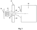
- an electron extractor, or extractor lens 36 is provided in close proximity to the filament 22 at a location between the filament 22 and the ion chamber 18.
- the term 'lens' is used as the extractor may provide a focussing function, but this term is non-limiting and it is not essential that the extractor 36 focuses the electrons.
- the extractor 36 comprises a metallic plate 38 having a centrally located aperture 40.
- the extractor may be a metallic grid or a frame with a metallic grid, or a plate having a plurality of apertures.
- the extractor 36 is arranged such that the plate or grid 38 is substantially perpendicular to the path of the electron beam 34 with the aperture or grid 40 being aligned with the path of the electron beam 34 such that electrons from the filament 22 travelling along the electron beam path 34 are permitted to pass through the aperture 40 and onwards to the ion chamber 18.
- the direct line of sight between the filament 22 and the opening 24 of the ion source chamber 18, comprising the shortest distance between the two, defines an electron beam path 34.
- the extractor 36 is charged to create a positive potential difference between the filament 22 and the extractor 36 that is greater than the potential difference between the filament 22 and the ion chamber 18.
- This larger potential difference acts to accelerate the electrons away from the filament 22 at a much higher rate than is achieved by the potential difference between the filament 22 and the ion chamber 18 alone, thereby reducing the electron density in the region of the filament 22, preventing coulombic repulsion from inhibiting electron emission and hence maximising the electron production from the filament.
- the potential difference between the filament 22 and the ion chamber 18 is selected to be in the range of 5-30 V thereby resulting in electron energies at the ion chamber in the range of 5-30 eV.
- the electron energy is too low to cause ionisation of the analyte molecules, whereas above this range fragmentation begins to occur.
- a yet more preferable range has been identified as being 5-25 V with an electron energy range of 5-25 eV, and more preferably again the system is operated at an electron energy of 14 eV.
- a reflecting plate 26 can be mounted behind the filament 22 on the opposing side of the filament 22 from the source chamber 18 such that the filament 22 is located between the source chamber 18 and the reflecting plate 26.
- the reflecting plate 26 is negatively charged such that the negatively charged electrons are repelled away from the reflecting plate 26 in the general direction of the ion source chamber 18. It is contemplated that in an alternative embodiment the apparatus may function without a reflecting plate, which is possible due to the extraction force applied by the extractor 36.
- the reflector can however provide increased efficiency by reducing electron losses in a direction away from the electron pathway.
- the electron beam 34 and gas inlet 16 to the ion chamber 18 are arranged such that the electron beam 34 enters the ion source chamber 18 substantially perpendicular to the flow of analyte into the ion chamber 18 from the gas inlet 16.
- the energetic electrons interact with the gas phase analyte molecules to produce ions.
- energy is transferred from the electrons to the analyte molecules causing ionisation of the molecule.
- This method is known as electron ionisation (EI).
- EI electron ionisation
- the level of fragmentation depends on the amount of energy transferred from the electron to the analyte molecule, which is in turn dependent on the energy of the incoming electrons. Therefore, by reducing the energy of the incoming electrons to a lower level, the fragmentation of the analyte is significantly reduced resulting in a larger concentration of unfragmented molecular ions.
- ions are ejected and then onwardly processed depending on the analysis technique to be used.
- a TOF mass spectrometer is used to analyse the analyte molecules.
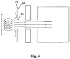
- the system further comprises a focussing lens 28 to focus the electron beam to increase electron density at the ion source chamber.
- the electron focussing lens 28 comprises a metallic plate 60 having a central aperture 61 formed therein.
- the aperture 61 is preferably of circular shape.
- the aperture 61 is located on the direct line of sight between the filament 22 and the opening 24 of the ion source chamber 18.
- the electron focussing lens 28 is arranged such that the plate 60 is substantially perpendicular to the path of the electron beam 34 with the aperture 61 being aligned with the path of the electron beam 34 such that electrons from the filament 22 travelling along the electron beam path 34 are permitted to pass through the aperture 61 and onwards to the ion chamber 18.
- the plate 60 of the electron focussing lens 28 is biased to a negative voltage.
- the negative voltage bias of the plate 60 creates a repulsive electrostatic field that acts to condense and focus the cloud of electrons omitted from the filament 22 through the aperture 61 and along the electron beam path 34.
- any broadening of the electron beam is countered by focussing the electrons using the electron focussing lens 28 and as a result the density of electrons along the electron path 34 is significantly increased.
- the number of electrons entering the ion chamber 18 is therefore increased and hence the probability of collision with analyte molecules resulting in ionisation rises accordingly.
- the electron focussing lens 28 includes an additional focussing element 62.
- the focussing element 62 comprises an upstanding wall circumferentially extending around the periphery of the aperture 61 and projecting from the surface of the disc 60 proximal to the filament 22.
- the focussing element 62 is substantially cylindrical in shape having its proximal end relative to the filament 22 open and its distal end contiguous with the aperture 61 of the lens 28.
- the focussing element 62 is preferably positioned such that it surrounds the filament 22 defining a channel surrounding the filament and extending between the filament 22 and the aperture 61 of the lens 28. In combination with the plate 60 the focussing element 62 forms a substantially 'top-hat' configuration.
- the top hat configuration enables the electron focussing lens 28 to be extended further towards and preferably over the filament 22.
- the 'top hat' shape increases funnelling of the electrons and decreases the amount of time the electrons can propagate and tangentially diverge before being focussed, thereby increasing electron density in the electron path 34. This is particularly important at the lower electron energies used in the present invention where electrons are subject to relatively higher tangential forces on generation and so their divergence is larger.
- fixed magnets 70 and 71 are provided for the embodiments in Figure 3 to 5 with the poles arranged to create a magnetic field which acts on the electrons to focus them in a helical manner to further optimise ionisation probability.
- Figure 7 shows an electrostatic field diagram representing the flow of electrons along the varying field between the filament and the ion source chamber. It can be seen that once the electrons are emitted from the filament 22 and have passed through the electron focussing lens 28 they accelerate rapidly towards the relatively positive potential difference of the extractor 36. This can be seen to cause a cascade of electrons away from the filament 22 thereby ensuring that the electron density immediately proximal to the filament 22 is maintained at suitably low levels promoting further electron production.
- the electron beam 34 passes through the extractor 36 it is subject to the potential difference between the extractor 36 and the ion chamber 18 which causes rapid deceleration of the electrons until they reach the set electron energy defined by the potential difference between filament and ion chamber 18 at the point of entering the ion chamber 18.
- the use of a positive potential between the electron focussing lens 28 and ion source chamber 18 in the form of an extractor 36 improves signal by reducing coulombic effects and increasing the number of electrons produced by the filament. This gives improved instrument sensitivity at the lower ionisation energies needed for soft ionisation.
- the further embodiment in which the electron focussing lens 28 is wrapped around the filament by means of a focussing element 62 has been shown to bring further signal enhancements.
- this ionisation method is suitable for real-time analysis (direct inlet of sample gas without GC separation), simplifying the necessary means for a direct inlet of atmospheric gases into the mass spectrometer.
- the above described soft electron ionisation technique is a universal ionisation method as compared for example to chemical ionisation. Apart from the lower ionisation energy it is non-specific to a large number of analytes. Therefore, it is suitable for screening analysis with reduced background signal (e.g. suppressed ionisation of siloxanes from column bleed or atmospheric gases, but ionisation of all the relevant organic compounds).
- the flexibility of electron ionisation allows for the application of switching or multiplexing multiple ionising voltages in one measurement. This gives the opportunity to simultaneously accumulate multiple sets of spectra, for example, one with hard ionisation (e.g. 70eV), and another with softer ionisation (e.g. 15eV). This could lead to increased levels of analytical information with little impact on cost, sensitivity, time, or the quantity of samples required.
- hard ionisation e.g. 70eV
- softer ionisation e.g. 15eV
- the analyte molecules For certain analysis it is desirable to be able to ionise the analyte molecules at two different ionisation energies. For example, for a given sample it may be desirable to obtain a first 'soft ionisation' data set and a second 'hard ionisation' data set for a given analyte source, with the first data set benefitting from decreased fragmentation and hence increased visibility of the molecular ions, while the harder ionisation provides increased ionisation efficiency and is able to be referenced against established data libraries.
- Fig. 3-6 There are several possibilities to stop or modulate the intensity of the electron beam in an embodiment according to Fig. 3-6 . This can be achieved by changing the voltage of one of the following elements: reflector 26, filament 22, focussing lens 28, extractor 36 and ion chamber 18. It also can be done by introducing an additional shutter lens or grid in the pathway 34 of the electron beam. By way of example only this is described using the focussing lens 28 as a modulator or shutter.
- the electron focussing lens 28 may also be configured to be used as a 'shutter' to selectively permit or block passage of the electron beam 34 to the ion chamber 18. By switching the electron focussing lens 28 to a different voltage it can be made to act as a 'gate', allowing or denying the electrons from reaching the ion source as required.
- the lens In an initial state the lens is set to 'pass' in which a first negative voltage is applied to the electron focussing lens 28.
- the first voltage is selected such that it is sufficiently negative to focus the electron beam while still allowing passage of the beam through the lens 28.
- the configuration of the central aperture of the lens 28 is such that the electrostatic field generated causes the electrons travelling towards the lens 28 to experience a repulsion force perpendicular to their movement towards the ion source chamber 18 which is directed radially inwards towards the aperture 61 of the lens 28.
- This field 'presses' the electrons into a narrow beam and directs them to pass through the lens 28.
- the compression of the electrons focuses them and increases the number of electrons that enter the ion source chamber 18. As such the efficiency and accuracy of ionisation within the chamber 18 is increased.
- the electron focussing lens 28 is set to 'stop' to prevent the flow of electrons to the ion source chamber 28.
- a second negative voltage is applied to the electron focussing lens 28 that is greater (i.e. more negative) than the first voltage. Due to the larger negative repulsion voltage, approaching electrons are prevented from passing through the electron focussing lens 28 due to electron repulsion and instead dissipate. As such, the flow of the electron beam 34 through the lens 28 is stopped and hence the flow of electrons to the ion source chamber 18 is halted and further ion generation is stalled.
- ion detection may be conducted on a cyclical basis through a series of 'scans'.
- Each scan is an individual data capture event commencing with the ionisation of molecules within the target zone.
- the electron focussing lens 28 is then operated as a shutter to halt ionisation and the ions are then extracted from the ion source 18 and propagated through the flight regions as described above.
- the scan concludes with the detection of the ions at the detector.
- the data acquisition frequency of the system is determined by the period of the scan. For example, for a scan period of around 100 ⁇ s the native data rate of the system will be approximately 10,000Hz.
- a relatively low quantity of ions is accumulated during a single scan, and as such any analysis based on a single scan alone would be subject to large statistical errors and would therefore be of limited use. It is also undesirable to acquire data from a single scan alone as the requirement to write data to a storage device for each scan period (i.e. every 100 ⁇ s) would result in extremely large and unmanageable file sizes. To avoid these problems the system sums the detected signals from multiple contiguous scans into 'scansets' with the accumulated signal being statistically more significant. Each scanset is then recorded as a single data point rather than multiple data points from each scan.
- a scanset rate of up to around 100Hz may be used, or one scanset every 0.01s. At this speed a scanset is comprised of 100 scans.
- a pause in the ionisation may be provided by utilising preferentially the electron focussing lens 28 as a shutter in the closed state in which ionisation is halted.
- the electron focussing lens 28 could also be used as a shutter: reflector, filament, focussing lens, extractor, ionisation chamber. Even a separate shutter element is conceivable.
- the duration of the pause between scans and between scansets can be different.
- the pause between scansets may be utilised to vary the electron ionisation voltage before the next scanset is commenced.
- Voltages controlling the reflector plate 26, extractor 36 and electron focussing lens 28 could be adjusted within the scanset pause, with the scanset pause period being selected to ensure a sufficiently stable voltage establishes before recommencement of the next scanset and subsequent data collection.
- a first scanset may be conducted at an electron acceleration voltage of 15V.
- the accelerating voltage is then increased to 70V and the next scanset is then conducted at the elevated voltage.
- the voltage is then reduced to 15V and this cycle of raising and lowering the accelerating voltage is continued on an intermittent alternating basis.
- the electron voltage may be effectively varied between scansets by varying the bias voltage of the filament 22 relative to the ion chamber 18 which defines the energy of the ionising electrons.
- the optimum voltages for the extractor and electron focussing lens 28 may vary with different ionisation energies, it could also be necessary to change these values alongside the voltage of the filament 22.
- multiple ionisation energies E x
- E x ionisation energies
- the rapid cyclical alternation of electron energies during a single sample analysis is enabled by the electron focussing lens 28 operating as a shutter halting ionisation between the scans and scansets, providing the scanset pause, and by the extractor 36 which enables analytically viable measurements to be made at soft ionisation energies by increasing electron density and hence ionisation efficiency at these lower energies.
- soft ionisation may be conducted by alternative means, such as chemical ionisation, and with reasonable efficiency, such techniques do not permit the ionisation energy to be varied during an analysis run as this would require a substitution of the ionisation gas which could not be effected in the required time periods.
- chemical ionisation allows only certain discrete ionisation energies, whereas the present invention permits any desired ionisation energy to be achieved within the voltage parametric range of the device.
- the alternation of the electron acceleration voltages between adjacent scansets supports the simultaneous production of two full sets of spectra; one ionised at E 1 and the other at E 2 .
- the ability to selectively vary the ionisation energy during an analysis could be applied in a variety of other ways.
- the ionisation energy could be selectively varied at a given predetermined time during the measurement of a sample.
- the present invention negates or mitigates the effects of space charge limited emission by extracting the electron cloud with a high field. Subsequent to the extraction the electrons are automatically decelerated while approaching the ion chamber. This allows low electron energies in the target region while maintaining a high electron production at the emitter.
- the ionisation technique is not limited to use with TOF mass spectrometry and it is contemplated that this system could be utilised for any application requiring ionisation of molecules and in particular where soft ionisation is required and/or the ability to switch between ionisation voltages within a single sample analysis.
Landscapes
- Chemical & Material Sciences (AREA)
- Engineering & Computer Science (AREA)
- Analytical Chemistry (AREA)
- Physics & Mathematics (AREA)
- Plasma & Fusion (AREA)
- Combustion & Propulsion (AREA)
- Other Investigation Or Analysis Of Materials By Electrical Means (AREA)
- Electron Tubes For Measurement (AREA)
- Analysing Materials By The Use Of Radiation (AREA)
- Geophysics And Detection Of Objects (AREA)
- Graft Or Block Polymers (AREA)
- Heterocyclic Carbon Compounds Containing A Hetero Ring Having Oxygen Or Sulfur (AREA)
Applications Claiming Priority (3)
| Application Number | Priority Date | Filing Date | Title |
|---|---|---|---|
| GB1302818.8A GB2518122B (en) | 2013-02-19 | 2013-02-19 | An electron ionisation apparatus |
| PCT/GB2014/050486 WO2014128462A2 (fr) | 2013-02-19 | 2014-02-19 | Appareil d'analyse mettant en œuvre l'ionisation par impact électronique |
| EP14706673.2A EP2959498B1 (fr) | 2013-02-19 | 2014-02-19 | Appareil d'analyse mettant en oeuvre l'ionisation par impact électronique |
Related Parent Applications (2)
| Application Number | Title | Priority Date | Filing Date |
|---|---|---|---|
| EP14706673.2A Division EP2959498B1 (fr) | 2013-02-19 | 2014-02-19 | Appareil d'analyse mettant en oeuvre l'ionisation par impact électronique |
| EP14706673.2A Division-Into EP2959498B1 (fr) | 2013-02-19 | 2014-02-19 | Appareil d'analyse mettant en oeuvre l'ionisation par impact électronique |
Publications (1)
| Publication Number | Publication Date |
|---|---|
| EP3736850A1 true EP3736850A1 (fr) | 2020-11-11 |
Family
ID=48048561
Family Applications (2)
| Application Number | Title | Priority Date | Filing Date |
|---|---|---|---|
| EP20183331.6A Pending EP3736850A1 (fr) | 2013-02-19 | 2014-02-19 | Procédé d'ionisation de molécules d'analyte pour analyse |
| EP14706673.2A Active EP2959498B1 (fr) | 2013-02-19 | 2014-02-19 | Appareil d'analyse mettant en oeuvre l'ionisation par impact électronique |
Family Applications After (1)
| Application Number | Title | Priority Date | Filing Date |
|---|---|---|---|
| EP14706673.2A Active EP2959498B1 (fr) | 2013-02-19 | 2014-02-19 | Appareil d'analyse mettant en oeuvre l'ionisation par impact électronique |
Country Status (7)
| Country | Link |
|---|---|
| US (2) | US9524858B2 (fr) |
| EP (2) | EP3736850A1 (fr) |
| JP (2) | JP6529912B2 (fr) |
| CN (2) | CN105051857B (fr) |
| CA (2) | CA2901549C (fr) |
| GB (1) | GB2518122B (fr) |
| WO (1) | WO2014128462A2 (fr) |
Families Citing this family (10)
| Publication number | Priority date | Publication date | Assignee | Title |
|---|---|---|---|---|
| GB2518122B (en) * | 2013-02-19 | 2018-08-08 | Markes International Ltd | An electron ionisation apparatus |
| GB2562170B (en) * | 2013-02-19 | 2019-02-06 | Markes International Ltd | A method of ionising analyte molecules for analysis |
| US20140374583A1 (en) * | 2013-06-24 | 2014-12-25 | Agilent Technologies, Inc. | Electron ionization (ei) utilizing different ei energies |
| US10176977B2 (en) | 2014-12-12 | 2019-01-08 | Agilent Technologies, Inc. | Ion source for soft electron ionization and related systems and methods |
| US9799504B2 (en) * | 2015-12-11 | 2017-10-24 | Horiba Stec, Co., Ltd. | Ion source, quadrupole mass spectrometer and residual gas analyzing method |
| JP6908138B2 (ja) * | 2018-02-06 | 2021-07-21 | 株式会社島津製作所 | イオン化装置及び質量分析装置 |
| JP7509762B2 (ja) | 2018-10-09 | 2024-07-02 | ディーエイチ テクノロジーズ デベロップメント プライベート リミテッド | 電子捕獲解離のための電子ビームスロットリング |
| WO2020081276A1 (fr) | 2018-10-19 | 2020-04-23 | Aceleron, Inc. | Procédés et systèmes pour l'auto-compression d'un plasma |
| CN111551628B (zh) * | 2020-06-08 | 2022-09-06 | 中国计量科学研究院 | 一种电子轰击电离源装置、电离轰击方法及物质分析方法 |
| GB2601524B (en) * | 2020-12-03 | 2024-01-17 | Isotopx Ltd | Apparatus and method |
Citations (8)
| Publication number | Priority date | Publication date | Assignee | Title |
|---|---|---|---|---|
| US5294797A (en) * | 1991-03-13 | 1994-03-15 | Bruker-Franzen Analytik Gmbh | Method and apparatus for generating ions from thermally unstable, non-volatile, large molecules, particularly for a mass spectrometer such as a time-of-flight mass spectrometer |
| US20040104682A1 (en) * | 2000-11-30 | 2004-06-03 | Horsky Thomas N. | Ion implantation system and control method |
| US20050051096A1 (en) * | 1999-12-13 | 2005-03-10 | Semequip, Inc. | Ion implantation ion source, system and method |
| US6919562B1 (en) * | 2002-05-31 | 2005-07-19 | Analytica Of Branford, Inc. | Fragmentation methods for mass spectrometry |
| US20060243901A1 (en) * | 2003-04-25 | 2006-11-02 | Barket Dennis Jr | Instrumentation, articles of manufacture, and analysis methods |
| US20090218482A1 (en) | 2005-08-19 | 2009-09-03 | Gsf-Forschungszentrum Fuer Umwelt Und Gesundheit, Gmbh | Method and device for the mass spectrometric detection of compounds |
| US20110049347A1 (en) * | 2009-08-25 | 2011-03-03 | Wells Gregory J | Electron capture dissociation apparatus and related methods |
| EP2819148A2 (fr) * | 2013-06-24 | 2014-12-31 | Agilent Technologies, Inc. | Ionisation électronique (EI) en utilisant différentes énergies d'ionisation électronique |
Family Cites Families (23)
| Publication number | Priority date | Publication date | Assignee | Title |
|---|---|---|---|---|
| US3836775A (en) * | 1973-03-08 | 1974-09-17 | Princeton Applied Res Corp | Electron impact spectrometer of high sensitivity and large helium tolerance and process of characterizing gaseous atoms and molecules by the energy loss spectrum |
| US4016421A (en) * | 1975-02-13 | 1977-04-05 | E. I. Du Pont De Nemours And Company | Analytical apparatus with variable energy ion beam source |
| JPH01140545A (ja) * | 1987-11-26 | 1989-06-01 | Nec Corp | イオンソース |
| JPH02121233A (ja) * | 1988-10-28 | 1990-05-09 | Nec Corp | イオン源 |
| JPH02282251A (ja) * | 1989-04-24 | 1990-11-19 | Fuji Photo Film Co Ltd | ハロゲン化銀カラー写真感光材料 |
| JPH05144397A (ja) * | 1991-11-20 | 1993-06-11 | Mitsubishi Electric Corp | イオン源 |
| US5340983A (en) * | 1992-05-18 | 1994-08-23 | The State Of Oregon Acting By And Through The State Board Of Higher Education On Behalf Of Oregon State University | Method and apparatus for mass analysis using slow monochromatic electrons |
| US5374828A (en) | 1993-09-15 | 1994-12-20 | The United States Of America As Represented By The Administrator Of The National Aeronautics And Space Administration | Electron reversal ionizer for detection of trace species using a spherical cathode |
| JPH07272652A (ja) * | 1994-03-29 | 1995-10-20 | Jeol Ltd | 電界電離型ガスフェーズイオン源の調整方法 |
| US6080985A (en) * | 1997-09-30 | 2000-06-27 | The Perkin-Elmer Corporation | Ion source and accelerator for improved dynamic range and mass selection in a time of flight mass spectrometer |
| JPH11135059A (ja) * | 1997-10-29 | 1999-05-21 | Anelva Corp | 放出ガス測定装置および放出ガス測定方法 |
| US7332345B2 (en) * | 1998-01-22 | 2008-02-19 | California Institute Of Technology | Chemical sensor system |
| JP3535402B2 (ja) * | 1999-02-01 | 2004-06-07 | 日本電子株式会社 | イオンビーム装置 |
| FR2792770A1 (fr) * | 1999-04-22 | 2000-10-27 | Cit Alcatel | Fonctionnement a haute pression d'une cathode froide a emission de champ |
| CN100385605C (zh) * | 2000-11-30 | 2008-04-30 | 赛米奎珀公司 | 离子注入系统及离子源 |
| US6686595B2 (en) * | 2002-06-26 | 2004-02-03 | Semequip Inc. | Electron impact ion source |
| KR100864048B1 (ko) * | 2002-06-26 | 2008-10-17 | 세미이큅, 인코포레이티드 | 이온 소스 |
| US7820981B2 (en) * | 2003-12-12 | 2010-10-26 | Semequip, Inc. | Method and apparatus for extending equipment uptime in ion implantation |
| US7030619B2 (en) * | 2004-02-19 | 2006-04-18 | Brooks Automation, Inc. | Ionization gauge |
| JP4232662B2 (ja) * | 2004-03-11 | 2009-03-04 | 株式会社島津製作所 | イオン化装置 |
| CN1965219A (zh) * | 2004-03-12 | 2007-05-16 | 布鲁克斯自动化有限公司 | 电离真空计 |
| US7288514B2 (en) * | 2005-04-14 | 2007-10-30 | The Clorox Company | Polymer-fluorosurfactant associative complexes |
| GB2518122B (en) * | 2013-02-19 | 2018-08-08 | Markes International Ltd | An electron ionisation apparatus |
-
2013
- 2013-02-19 GB GB1302818.8A patent/GB2518122B/en active Active
-
2014
- 2014-02-19 CA CA2901549A patent/CA2901549C/fr active Active
- 2014-02-19 WO PCT/GB2014/050486 patent/WO2014128462A2/fr not_active Ceased
- 2014-02-19 EP EP20183331.6A patent/EP3736850A1/fr active Pending
- 2014-02-19 CA CA3076641A patent/CA3076641C/fr active Active
- 2014-02-19 JP JP2015557524A patent/JP6529912B2/ja active Active
- 2014-02-19 CN CN201480009237.4A patent/CN105051857B/zh active Active
- 2014-02-19 CN CN201711064231.9A patent/CN107731653B/zh active Active
- 2014-02-19 EP EP14706673.2A patent/EP2959498B1/fr active Active
- 2014-02-19 US US14/767,920 patent/US9524858B2/en active Active
-
2016
- 2016-08-08 US US15/231,383 patent/US9786480B2/en active Active
-
2018
- 2018-12-27 JP JP2018245132A patent/JP6854799B2/ja active Active
Patent Citations (8)
| Publication number | Priority date | Publication date | Assignee | Title |
|---|---|---|---|---|
| US5294797A (en) * | 1991-03-13 | 1994-03-15 | Bruker-Franzen Analytik Gmbh | Method and apparatus for generating ions from thermally unstable, non-volatile, large molecules, particularly for a mass spectrometer such as a time-of-flight mass spectrometer |
| US20050051096A1 (en) * | 1999-12-13 | 2005-03-10 | Semequip, Inc. | Ion implantation ion source, system and method |
| US20040104682A1 (en) * | 2000-11-30 | 2004-06-03 | Horsky Thomas N. | Ion implantation system and control method |
| US6919562B1 (en) * | 2002-05-31 | 2005-07-19 | Analytica Of Branford, Inc. | Fragmentation methods for mass spectrometry |
| US20060243901A1 (en) * | 2003-04-25 | 2006-11-02 | Barket Dennis Jr | Instrumentation, articles of manufacture, and analysis methods |
| US20090218482A1 (en) | 2005-08-19 | 2009-09-03 | Gsf-Forschungszentrum Fuer Umwelt Und Gesundheit, Gmbh | Method and device for the mass spectrometric detection of compounds |
| US20110049347A1 (en) * | 2009-08-25 | 2011-03-03 | Wells Gregory J | Electron capture dissociation apparatus and related methods |
| EP2819148A2 (fr) * | 2013-06-24 | 2014-12-31 | Agilent Technologies, Inc. | Ionisation électronique (EI) en utilisant différentes énergies d'ionisation électronique |
Also Published As
| Publication number | Publication date |
|---|---|
| JP2016513343A (ja) | 2016-05-12 |
| WO2014128462A3 (fr) | 2014-12-18 |
| GB2518122B (en) | 2018-08-08 |
| CN107731653A (zh) | 2018-02-23 |
| US20160343560A1 (en) | 2016-11-24 |
| US9524858B2 (en) | 2016-12-20 |
| JP2019091699A (ja) | 2019-06-13 |
| CA3076641A1 (fr) | 2014-08-28 |
| CA2901549A1 (fr) | 2014-08-28 |
| US9786480B2 (en) | 2017-10-10 |
| CN107731653B (zh) | 2019-11-08 |
| GB2518122A (en) | 2015-03-18 |
| CA3076641C (fr) | 2024-01-30 |
| HK1216690A1 (en) | 2016-11-25 |
| JP6854799B2 (ja) | 2021-04-07 |
| US20150380228A1 (en) | 2015-12-31 |
| EP2959498B1 (fr) | 2021-01-06 |
| CN105051857A (zh) | 2015-11-11 |
| CN105051857B (zh) | 2017-11-17 |
| WO2014128462A2 (fr) | 2014-08-28 |
| JP6529912B2 (ja) | 2019-06-12 |
| GB201302818D0 (en) | 2013-04-03 |
| CA2901549C (fr) | 2025-02-04 |
| EP2959498A2 (fr) | 2015-12-30 |
Similar Documents
| Publication | Publication Date | Title |
|---|---|---|
| CA3076641C (fr) | Appareil d'analyse mettant en oeuvre l'ionisation par impact electronique | |
| JP6739931B2 (ja) | ソフト電子イオン化のためのイオン源ならびに関連するシステムおよび方法 | |
| EP2831904B1 (fr) | Appareil pour permettre l'acquisition parallèle de spectrométrie de masse/données de spectrométrie de masse | |
| JP2015514300A5 (fr) | ||
| GB2445804A (en) | Tandem mass spectrometry system | |
| US20110049350A1 (en) | Tandem TOF Mass Spectrometer With Pulsed Accelerator To Reduce Velocity Spread | |
| US7994474B2 (en) | Laser desorption ionization ion source with charge injection | |
| US5898173A (en) | High resolution ion detection for linear time-of-flight mass spectrometers | |
| EP2413346B1 (fr) | Source d'ions et spectromètre de masse doté de celle-ci | |
| US3769513A (en) | Ion kinetic energy spectrometer | |
| HK1216690B (en) | An analytical apparatus utilising electron impact ionisation | |
| GB2562170A (en) | A method of ionising analyte molecules for analysis | |
| JP4450717B2 (ja) | 質量分析装置 | |
| WO2026082720A1 (fr) | Source d'ions à bombardement électronique | |
| JP2006322776A (ja) | 飛行時間質量分析計 | |
| JP2007335368A (ja) | 飛行時間型質量分析方法および装置 | |
| CN112640033A (zh) | 用于飞行时间质谱仪的脉冲式加速器 | |
| Ximen et al. | Design and calculation of an electron impact storage ion source for time-of-flight mass spectrometers | |
| JP2019110000A (ja) | 化合物分離回収装置 |
Legal Events
| Date | Code | Title | Description |
|---|---|---|---|
| PUAI | Public reference made under article 153(3) epc to a published international application that has entered the european phase |
Free format text: ORIGINAL CODE: 0009012 |
|
| STAA | Information on the status of an ep patent application or granted ep patent |
Free format text: STATUS: THE APPLICATION HAS BEEN PUBLISHED |
|
| AC | Divisional application: reference to earlier application |
Ref document number: 2959498 Country of ref document: EP Kind code of ref document: P |
|
| AK | Designated contracting states |
Kind code of ref document: A1 Designated state(s): AL AT BE BG CH CY CZ DE DK EE ES FI FR GB GR HR HU IE IS IT LI LT LU LV MC MK MT NL NO PL PT RO RS SE SI SK SM TR |
|
| STAA | Information on the status of an ep patent application or granted ep patent |
Free format text: STATUS: REQUEST FOR EXAMINATION WAS MADE |
|
| 17P | Request for examination filed |
Effective date: 20210511 |
|
| RBV | Designated contracting states (corrected) |
Designated state(s): AL AT BE BG CH CY CZ DE DK EE ES FI FR GB GR HR HU IE IS IT LI LT LU LV MC MK MT NL NO PL PT RO RS SE SI SK SM TR |
|
| STAA | Information on the status of an ep patent application or granted ep patent |
Free format text: STATUS: EXAMINATION IS IN PROGRESS |
|
| 17Q | First examination report despatched |
Effective date: 20230131 |
|
| GRAP | Despatch of communication of intention to grant a patent |
Free format text: ORIGINAL CODE: EPIDOSNIGR1 |
|
| STAA | Information on the status of an ep patent application or granted ep patent |
Free format text: STATUS: GRANT OF PATENT IS INTENDED |
|
| INTG | Intention to grant announced |
Effective date: 20260105 |