EP3736883A1 - Module de batterie comprenant une batterie secondaire et une barre omnibus - Google Patents
Module de batterie comprenant une batterie secondaire et une barre omnibus Download PDFInfo
- Publication number
- EP3736883A1 EP3736883A1 EP19822155.8A EP19822155A EP3736883A1 EP 3736883 A1 EP3736883 A1 EP 3736883A1 EP 19822155 A EP19822155 A EP 19822155A EP 3736883 A1 EP3736883 A1 EP 3736883A1
- Authority
- EP
- European Patent Office
- Prior art keywords
- bus bar
- battery module
- electrode lead
- electrode
- plate
- Prior art date
- Legal status (The legal status is an assumption and is not a legal conclusion. Google has not performed a legal analysis and makes no representation as to the accuracy of the status listed.)
- Granted
Links
Images


Classifications
-
- H—ELECTRICITY
- H01—ELECTRIC ELEMENTS
- H01M—PROCESSES OR MEANS, e.g. BATTERIES, FOR THE DIRECT CONVERSION OF CHEMICAL ENERGY INTO ELECTRICAL ENERGY
- H01M50/00—Constructional details or processes of manufacture of the non-active parts of electrochemical cells other than fuel cells, e.g. hybrid cells
- H01M50/10—Primary casings; Jackets or wrappings
- H01M50/172—Arrangements of electric connectors penetrating the casing
-
- H—ELECTRICITY
- H01—ELECTRIC ELEMENTS
- H01M—PROCESSES OR MEANS, e.g. BATTERIES, FOR THE DIRECT CONVERSION OF CHEMICAL ENERGY INTO ELECTRICAL ENERGY
- H01M50/00—Constructional details or processes of manufacture of the non-active parts of electrochemical cells other than fuel cells, e.g. hybrid cells
- H01M50/50—Current conducting connections for cells or batteries
- H01M50/502—Interconnectors for connecting terminals of adjacent batteries; Interconnectors for connecting cells outside a battery casing
- H01M50/503—Interconnectors for connecting terminals of adjacent batteries; Interconnectors for connecting cells outside a battery casing characterised by the shape of the interconnectors
-
- H—ELECTRICITY
- H01—ELECTRIC ELEMENTS
- H01M—PROCESSES OR MEANS, e.g. BATTERIES, FOR THE DIRECT CONVERSION OF CHEMICAL ENERGY INTO ELECTRICAL ENERGY
- H01M10/00—Secondary cells; Manufacture thereof
- H01M10/05—Accumulators with non-aqueous electrolyte
- H01M10/052—Li-accumulators
-
- H—ELECTRICITY
- H01—ELECTRIC ELEMENTS
- H01M—PROCESSES OR MEANS, e.g. BATTERIES, FOR THE DIRECT CONVERSION OF CHEMICAL ENERGY INTO ELECTRICAL ENERGY
- H01M50/00—Constructional details or processes of manufacture of the non-active parts of electrochemical cells other than fuel cells, e.g. hybrid cells
- H01M50/10—Primary casings; Jackets or wrappings
- H01M50/172—Arrangements of electric connectors penetrating the casing
- H01M50/174—Arrangements of electric connectors penetrating the casing adapted for the shape of the cells
- H01M50/178—Arrangements of electric connectors penetrating the casing adapted for the shape of the cells for pouch or flexible bag cells
-
- H—ELECTRICITY
- H01—ELECTRIC ELEMENTS
- H01M—PROCESSES OR MEANS, e.g. BATTERIES, FOR THE DIRECT CONVERSION OF CHEMICAL ENERGY INTO ELECTRICAL ENERGY
- H01M50/00—Constructional details or processes of manufacture of the non-active parts of electrochemical cells other than fuel cells, e.g. hybrid cells
- H01M50/20—Mountings; Secondary casings or frames; Racks, modules or packs; Suspension devices; Shock absorbers; Transport or carrying devices; Holders
- H01M50/204—Racks, modules or packs for multiple batteries or multiple cells
- H01M50/207—Racks, modules or packs for multiple batteries or multiple cells characterised by their shape
- H01M50/209—Racks, modules or packs for multiple batteries or multiple cells characterised by their shape adapted for prismatic or rectangular cells
-
- H—ELECTRICITY
- H01—ELECTRIC ELEMENTS
- H01M—PROCESSES OR MEANS, e.g. BATTERIES, FOR THE DIRECT CONVERSION OF CHEMICAL ENERGY INTO ELECTRICAL ENERGY
- H01M50/00—Constructional details or processes of manufacture of the non-active parts of electrochemical cells other than fuel cells, e.g. hybrid cells
- H01M50/20—Mountings; Secondary casings or frames; Racks, modules or packs; Suspension devices; Shock absorbers; Transport or carrying devices; Holders
- H01M50/204—Racks, modules or packs for multiple batteries or multiple cells
- H01M50/207—Racks, modules or packs for multiple batteries or multiple cells characterised by their shape
- H01M50/211—Racks, modules or packs for multiple batteries or multiple cells characterised by their shape adapted for pouch cells
-
- H—ELECTRICITY
- H01—ELECTRIC ELEMENTS
- H01M—PROCESSES OR MEANS, e.g. BATTERIES, FOR THE DIRECT CONVERSION OF CHEMICAL ENERGY INTO ELECTRICAL ENERGY
- H01M50/00—Constructional details or processes of manufacture of the non-active parts of electrochemical cells other than fuel cells, e.g. hybrid cells
- H01M50/20—Mountings; Secondary casings or frames; Racks, modules or packs; Suspension devices; Shock absorbers; Transport or carrying devices; Holders
- H01M50/249—Mountings; Secondary casings or frames; Racks, modules or packs; Suspension devices; Shock absorbers; Transport or carrying devices; Holders specially adapted for aircraft or vehicles, e.g. cars or trains
-
- H—ELECTRICITY
- H01—ELECTRIC ELEMENTS
- H01M—PROCESSES OR MEANS, e.g. BATTERIES, FOR THE DIRECT CONVERSION OF CHEMICAL ENERGY INTO ELECTRICAL ENERGY
- H01M50/00—Constructional details or processes of manufacture of the non-active parts of electrochemical cells other than fuel cells, e.g. hybrid cells
- H01M50/50—Current conducting connections for cells or batteries
- H01M50/502—Interconnectors for connecting terminals of adjacent batteries; Interconnectors for connecting cells outside a battery casing
- H01M50/505—Interconnectors for connecting terminals of adjacent batteries; Interconnectors for connecting cells outside a battery casing comprising a single busbar
-
- H—ELECTRICITY
- H01—ELECTRIC ELEMENTS
- H01M—PROCESSES OR MEANS, e.g. BATTERIES, FOR THE DIRECT CONVERSION OF CHEMICAL ENERGY INTO ELECTRICAL ENERGY
- H01M50/00—Constructional details or processes of manufacture of the non-active parts of electrochemical cells other than fuel cells, e.g. hybrid cells
- H01M50/50—Current conducting connections for cells or batteries
- H01M50/531—Electrode connections inside a battery casing
- H01M50/533—Electrode connections inside a battery casing characterised by the shape of the leads or tabs
-
- H—ELECTRICITY
- H01—ELECTRIC ELEMENTS
- H01M—PROCESSES OR MEANS, e.g. BATTERIES, FOR THE DIRECT CONVERSION OF CHEMICAL ENERGY INTO ELECTRICAL ENERGY
- H01M50/00—Constructional details or processes of manufacture of the non-active parts of electrochemical cells other than fuel cells, e.g. hybrid cells
- H01M50/50—Current conducting connections for cells or batteries
- H01M50/543—Terminals
- H01M50/552—Terminals characterised by their shape
- H01M50/553—Terminals adapted for prismatic, pouch or rectangular cells
- H01M50/557—Plate-shaped terminals
-
- H—ELECTRICITY
- H01—ELECTRIC ELEMENTS
- H01M—PROCESSES OR MEANS, e.g. BATTERIES, FOR THE DIRECT CONVERSION OF CHEMICAL ENERGY INTO ELECTRICAL ENERGY
- H01M2220/00—Batteries for particular applications
- H01M2220/20—Batteries in motive systems, e.g. vehicle, ship, plane
-
- Y—GENERAL TAGGING OF NEW TECHNOLOGICAL DEVELOPMENTS; GENERAL TAGGING OF CROSS-SECTIONAL TECHNOLOGIES SPANNING OVER SEVERAL SECTIONS OF THE IPC; TECHNICAL SUBJECTS COVERED BY FORMER USPC CROSS-REFERENCE ART COLLECTIONS [XRACs] AND DIGESTS
- Y02—TECHNOLOGIES OR APPLICATIONS FOR MITIGATION OR ADAPTATION AGAINST CLIMATE CHANGE
- Y02E—REDUCTION OF GREENHOUSE GAS [GHG] EMISSIONS, RELATED TO ENERGY GENERATION, TRANSMISSION OR DISTRIBUTION
- Y02E60/00—Enabling technologies; Technologies with a potential or indirect contribution to GHG emissions mitigation
- Y02E60/10—Energy storage using batteries
Definitions
- the present disclosure relates to a battery module including a secondary battery and a bus bar, and more particularly, to a battery module allowing easy fabrication between the secondary battery and the bus bar and ensuring improved product durability and improved space utilization rate.
- Secondary batteries currently commercialized include nickel cadmium batteries, nickel hydrogen batteries, nickel zinc batteries, lithium secondary batteries and so on.
- the lithium secondary batteries are more highlighted in comparison to nickel-based secondary batteries due to advantages such as free charging and discharging, caused by substantially no memory effect, very low self-discharge rate, and high energy density.
- the lithium secondary battery mainly uses lithium-based oxides and carbonaceous materials as a positive electrode active material and a negative electrode active material, respectively.
- the lithium secondary battery includes an electrode assembly in which a positive electrode plate coated with the positive electrode active material and a negative electrode plate coated with the negative electrode active material are disposed with a separator being interposed therebetween, and an exterior, namely a battery pouch exterior, hermetically containing the electrode assembly together with an electrolyte.
- the lithium secondary battery may be classified into a can-type secondary battery in which the electrode assembly is included in a metal can and a pouch-type secondary battery in which the electrode assembly is included in a pouch made of aluminum laminate sheets, depending on the shape of the exterior.
- secondary batteries have been widely used not only in small-sized devices such as portable electronic devices but also in medium-sized or large-sized devices such as vehicles and power storage devices.
- the secondary batteries are used in the middle-sized or large-sized devices, a large number of secondary batteries are electrically connected to increase capacity and power.
- pouch-type secondary batteries are widely used for the middle-sized or large-sized devices since they may be easily stacked.
- electrode leads are connected to each other, and the connection portions may be welded to maintain the connected state.
- the battery module may have parallel and/or series electrical connections between the secondary batteries.
- one end of the electrode lead may be fixed in contact to the bus bar by welding or the like for electrical connection between to each secondary battery.
- the electrical connection between the secondary batteries is frequently configured by bonding the electrode leads to the bus bar.
- electrode leads of the same polarity are bonded to each other.
- electrode leads of different polarities are bonded to each other.
- a process of bending an end of an electrode lead is performed so that the electrode lead of a secondary battery is connected and contacted to a bus bar, and the bent portion of the electrode lead may be joined to one surface of the bus bar by means of laser or ultrasonic welding.
- the electrode lead bending process it is required to bend a plurality of electrode leads formed at a plurality of secondary batteries one by one, which leads to large workloads.
- the bent end of the electrode lead made of a flexible material since it is not easy to allow the bent end of the electrode lead made of a flexible material to stably contact one surface of the bus bar, the welding process is difficult and high welding reliability is not easily secured.
- the present disclosure is designed to solve the problems of the related art, and therefore the present disclosure is directed to providing a battery module, which may allow easy fabrication between a secondary battery and a bus bar and ensure improved product durability and improved space utilization rate.
- a battery module comprising:
- the head may be formed such that a thickness thereof in a direction facing the bus bar is greater than a thickness of the body in a direction perpendicular to a relatively broader side surface of the body among side surfaces of the body.
- At least a portion of the body may have a thickness gradually increasing toward the head.
- the body may have a stopper formed at a portion thereof to protrude outward.
- the body may be shaped such that at least a portion thereof has a width gradually decreasing toward the head.
- the electrode lead may include a first electrode lead and a second electrode lead provided at the same side surface of the secondary battery and having different electric polarities.
- heads of the first electrode lead and the second electrode lead may be formed to be biased to one side or the other side with respect to the center of the body so as to be positioned adjacent to each other.
- a fixing protrusion protruding toward the body of the electrode lead, which is inserted into the slit may be formed at a portion of an inner surface of the slit.
- the slit may have a spaced width gradually decreasing inward from one end thereof.
- a secondary battery comprising: an electrode assembly having a positive electrode plate and a negative electrode plate with a separator being interposed therebetween; an electrolyte; an exterior case configured to accommodate the electrode assembly and the electrolyte in an inner space thereof; and an electrode lead having a body whose one end is electrically connected to the positive electrode plate or the negative electrode plate of the electrode assembly and the other end protrudes outward from the exterior case so that a portion of the body is inserted into a slit formed at a bus bar having a plate shape at least partially made of an electrically conductive material to extend inward from one end of the bus bar and a plate-shaped head extending in both directions perpendicular to the protruding direction of the body from the other end of the body, the electrode lead being at least partially made of an electrically conductive material.
- a battery pack comprising at least one battery module according to the present disclosure.
- a vehicle comprising the battery pack according to the present disclosure.
- the electrode lead of the secondary battery has a body and a head
- one surface of the head may be disposed in contact with one surface of the bus bar without performing a process of separately bending an end of the electrode lead to contact one surface of the bus bar, thereby effectively reducing the process time and manufacturing cost for the battery module.
- a stopper is formed at a portion of the body of the electrode lead of the secondary battery, it is possible to prevent the head from moving in the upper and lower direction when the portion of the body is inserted into the slit of the bus bar, and also the lower surface of the head may be fixed to the upper surface of the bus bar. Accordingly, the electrode lead and the bus bar may be welded easily.
- the electrode lead of the secondary battery since the electrode lead of the secondary battery has an inclined structure formed at a portion of the body, the material cost of the electrode lead may be reduced, and also the body may be inserted into the slit of the bus bar by using the inclined structure. In addition, the length of the body inserted into the slit may be reduced, and thus the inserting process may be performed more easily.
- the bus bars respectively connected to the first electrode lead and the second electrode lead may be located close to the center of the secondary battery, thereby effectively reducing the volume of the appearance of the battery module.
- the inserted electrode lead may stably keep its inserted and fixed state, and thus the bus bar and the electrode lead may be welded easily.
- the inserted electrode lead may keep its inserted and fixed state stably by the decreased slit width, and thus the bus bar and the electrode lead may be welded easily.
- FIG. 1 is a perspective view schematically showing a battery module according to an embodiment of the present disclosure.
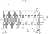
- FIG. 2 is a plane view schematically showing the battery module according to an embodiment of the present disclosure.
- FIG. 3 is an exploded plane view schematically showing components of the battery module according to an embodiment of the present disclosure in a separated state.
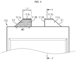
- FIG. 4 is a front view schematically showing a secondary battery, which is a component of the battery module according to an embodiment of the present disclosure.
- FIG. 5 is a longitudinal sectioned view schematically showing the battery module, taken along the line A-A' of FIG. 4 .
- a battery module 100 may include a plurality of secondary batteries 110. Also, the plurality of secondary batteries 110 may be arranged in a front and rear direction, when viewed in the F direction.
- the terms indicating directions such as front, rear, left, right, upper and lower, used in this specification, may vary depending on the position of an observer or the shape of an object.
- the front, rear, left, right, upper and lower directions are distinguished based on the case where viewed in the F direction.
- the secondary battery 110 may be a pouch-type secondary battery 110.
- the pouch-type secondary battery 110 may include an electrode assembly 113, an electrolyte 115, and an exterior case 117.
- the electrode assembly 113 may be configured to have at least one positive electrode plate 113a and at least one negative electrode plate 113b with a separator 113c being interposed therebetween. More specifically, the electrode assembly 113 may be a stack-type electrode assembly in which a plurality of positive electrode plates 113a and a plurality of negative electrode plates 113b are alternately stacked with the separators 113c being interposed therebetween. For example, as shown in FIG. 5 , the electrode assembly 113 of the present disclosure may be a stack-type electrode assembly in which a plurality of positive electrode plates 113a and a plurality of negative electrode plates 113b are alternately stacked with the separators 113c being interposed therebetween.
- the secondary battery 110 may be a lithium secondary battery 110 provided with a lithium-based active material.
- the exterior case 117 may accommodate the electrode assembly 113 and the electrolyte 115 in an inner space thereof.
- the exterior case 117 may be a pouch-type exterior case 117.
- the pouch-type exterior case 117 may include an outer insulating layer, a metal layer, and an inner adhesive layer.
- the pouch-type exterior case 117 may accommodate the electrode assembly 113 therein.
- the pouch-type exterior case 117 may be configured to contain a metal film, for example an aluminum film, in order to protect internal components such as the electrode assembly 113 and the electrolyte 115 and to improve the electrochemical properties and the heat dissipation properties of the electrode assembly 113 and the electrolyte 115.
- a metal film for example an aluminum film
- the aluminum film may be interposed between insulating layers made of an insulating material in order to ensure electrical insulation with internal components of the secondary battery 110 such as the electrode assembly 113 and the electrolyte 115 or with other components out of the secondary battery 110.
- the pouch-type exterior case 117 may include two pouches, and a concave inner space may be formed in at least one of the pouches.
- the electrode assembly 113 may be accommodated in the inner space of the exterior case 117.
- sealing portions 117a may be provided to outer circumferences of the two pouches so that the sealing portions 117a are fused to each other to seal the inner space in which the electrode assembly 113 is accommodated.
- the pouch-type secondary battery 110 may include an electrode lead 111.
- the electrode lead 111 may include a positive electrode lead 111A and a negative electrode lead 111B.
- the electrode lead 111 may be configured to protrude outward from the sealing portion 117a located at the upper outer circumference of the pouch-type exterior case 117.
- the electrode lead 111 may function as an electrode terminal of the secondary battery 110.
- the electrode lead 111 formed at the secondary battery 110 may include a body 111a and a head 111b.
- the body 111a may at least partially have a plate shape. That is, for example, as shown in FIG. 4 , the electrode lead 111 may be erected in the upper and lower direction with respect to the ground when viewed from the front (in the F direction of FIG. 1 ), and two broad surfaces may be located in the front and rear direction.
- one end of the electrode lead 111 may be electrically connected to the positive electrode plate 113a or the negative electrode plate 113b of the electrode assembly 113. More specifically, a positive electrode tab 113a2 and a negative electrode tab (not shown) protruding and extending outward may be respectively formed at one ends of the positive electrode plate 113a and the negative electrode plate 113b. In addition, a portion of the positive electrode tab 113a2 and a portion of the negative electrode tab may be in contact with one end of the electrode lead 111.
- one end of the body 111a at an inward side may be located inside the exterior case 117. That is, the inward end of the body 111a may be located inside the exterior case 117 to contact a portion of the positive electrode tab 113a2 and a portion of the negative electrode tab (not shown).
- the other end of the body 111a may be formed to protrude outward from the exterior case 117. That is, the outward end of the body 111a may be positioned to be exposed out of the exterior case 117.
- one end of the body 111a of the electrode lead 111 at a lower side may be located inside the exterior case 117.
- the other end of the body 111a at an upper side may be formed to protrude upward from the exterior case 117.
- the head 111b may have a plate shape extending in both directions W perpendicular to the protruding direction of the body 111a from the other end of the body 111a.
- the electrode lead 111 has a plate-shaped head 111b extending in both directions (in the front and rear directions) perpendicular to the protruding direction (the upper and lower directions) of the body 111a from the other end of the body 111a.
- the electrode lead 111 since the electrode lead 111 has the body 111a and the head 111b, when the head 111b is joined to the bus bar 120, one surface of the head 111b may be disposed to be in contact with one surface of the bus bar 120 without performing a process of bending the electrode lead 111 so that an end of the electrode lead 111 comes into contact with one surface of the bus bar 120, thereby effectively reducing the process time and manufacturing cost for the battery module 100.
- the electrode lead 111 may be at least partially made of an electrically conductive material.
- the electrode lead 111 may include copper, aluminum, nickel, and combinations thereof as the electrically conductive material.
- the configuration of the pouch-type secondary battery 110 described above is obvious to those skilled in the art and thus will not described in detail.
- the battery module according to the present disclosure may adopt various kinds of secondary batteries 110 known at the time of filing this application.
- the battery module 100 may include at least one bus bar 120.
- the bus bar 120 may be configured to have a plate form at least partially made of an electrically conductive material.
- the electrically conductive material may include, for example, copper, aluminum, nickel, and combinations thereof.
- the battery module 100 may include thirteen bus bars 120.
- the thirteen bus bars 120 may at least partially have a rectangular plate form.
- the bus bar 120 may have at least one slit 122 formed thereto to extend inward from one end thereof.
- a portion of the body 111a may be inserted into the slit 122.
- a lower surface of the head 111b may be positioned to face an upper surface of the bus bar 120.
- At least one slit 122 extending into the bus bar 120 from one end of the bus bar adjacent to the secondary battery 110 may be formed at each of the thirteen bus bars 120.
- a portion of the body 111a of each of the plurality of secondary batteries 110 may be inserted into each slit 122 formed at the thirteen bus bars 120.
- the lower surface of the head 111b may be positioned to face the upper surface of the bus bar 120.
- the battery module 100 when viewed in the F direction, may include seven bus bars 120 at one side (a left side) with respect to a center line P of the battery module 100 in the front and rear direction. Further, as shown in FIG. 3 , the seven bus bars 120 may move toward the center of the battery module 100 and be coupled thereto such that the twelve electrode leads 111 in total formed at one side with respect to the center line of the battery module 100 are inserted into twelve slits 122 formed at the seven bus bars 120, respectively.
- the six bus bars 120 located at the other side (a right side) with respect to the center line P of the battery module 100 in the front and rear direction may move toward the center of the battery module 100 and be coupled thereto such that twelve electrode leads 111 in total formed at the other side with respect to the center line of the battery module 100 are inserted into twelve slits 122 formed at the six bus bars 120, respectively.
- the bus bar 120 may have a plate portion 124 having a plate shape and an upward extending portion 126 extending upward from the plate portion 124.
- an external input/output terminal 127 may be formed at the upward extending portion 126 of the bus bar 120.
- two bus bars 120A respectively positioned at the foremost and rearmost sides of the battery module 100 may include a plate portion 124 and an upward extending portion 126.
- a bolt-type external input/output terminal 127 may be inserted into and fixed to the upward extending portion 126.
- the head 111b may have a thickness Z in a direction facing the bus bar 120, which is greater than a thickness E of the body 111a in a direction perpendicular to a relatively broader side surface of the body 111a among side surfaces of the body 111a.
- the thickness Z of the head 111b in the upper and lower direction may be greater than the thickness E of the body 111a in the front and rear direction.
- the thickness E of the broad side surface of the body 111a may be 0.2 mm to 0.4 mm.
- the head 111b may have a thickness Z of about 1.0 mm in the upper and lower direction.
- the head 111b is formed thicker than the body 111a, the region of the electrode lead 111 melted and bonded to the bus bar 120 when welded thereto may be increased, compared to the conventional electrode lead 111 that is welded in thickness of 0.2 mm to 0.4 mm, thereby greatly increasing connection reliability and joining strength.
- the body 111a may have a thickness E gradually increasing toward the head 111b in a direction perpendicular to the relatively broader side surface of the body 111a among the side surfaces of body 111a.
- the body 111a has a structure (a tapered structure) T1 whose thickness gradually increases from a portion of the body 111a exposed out of the exterior case 117 to an inner surface (a lower surface) of the head 111b.
- the connecting portion between the lower surface of the head 111b and the other end of the body 111a may have enhanced mechanical rigidity. By doing so, it is possible to prevent the connection portion between the lower surface of the head 111b and the other end of the body 111a from being damaged by physical force or vibration while being welded with the bus bar 120.
- FIG. 6 is a longitudinal sectioned view schematically showing a secondary battery, employed at the battery module according to another embodiment of the present disclosure.
- a stopper S2 protruding outward may be formed on a portion of the body 111a.
- the stopper S2 may be formed on a relatively broader side surface among the side surfaces of the electrode lead 111.
- a protrusion-shaped stopper S2 protruding forward or rearward may be formed on each of the front surface and the rear surface of the electrode lead 111.
- the outward direction means a direction toward a relatively outer side with respect to the inner center of the battery module.
- the horizontal direction means a direction parallel to the ground on which the battery module is placed.
- the stopper S2 is formed on a portion of the body 111a of the electrode lead 111, when a portion of the body 111a is inserted into the slit 122 of the bus bar 120, the head 111b may be prevented from moving in the upper and lower direction, and the lower surface of the head 111b may be fixed on the upper surface of the bus bar 120. As a result, the electrode lead 111 and the bus bar 120 may be welded more easily.
- the body 111a may have a width gradually decreasing toward the head 111b.
- the body 111a may be shaped such that its width W2 in the left and right direction gradually decreases as being closer to the head 111b, namely to have an inclined structure S1.
- the head 111b may be formed to have a length L1 similar to the width W2 of the end of the body 111a.
- the electrode lead 111 may include a first electrode lead 111A and a second electrode lead 111B provided at the same side surface of the secondary battery 110 and having different electrical polarities from each other.
- the positive electrode lead 111A may have an inclined structure S1 such that at least a portion of the body 111a has a width gradually decreasing as being closer to the head 111b.
- the inclined structure S1 of the positive electrode lead 111A may be formed at a right side with respect to the center of the body 111a of the positive electrode lead 111A.
- the negative electrode lead 111B may have an inclined structure S1 such that at least a portion of the body 111a has a width gradually decreasing as being closer to the head 111b.
- the inclined structure of the negative electrode lead 111B may be formed at a left side with respect to the center of the body 111a of the negative electrode lead 111B.
- the inclined structure S1 is formed in at least a portion of the body 111a of the electrode lead 111, it is possible to reduce the material cost of the electrode lead 111. Moreover, since the body 111a may be inserted into the slit 122 of the bus bar 120 by using the inclined structure S1 and the length of the body 111a inserted into the slit 122 may be shortened, the inserting process may be performed more easily.
- the heads 111b of the first electrode lead 111A and the second electrode lead 111B may be formed to be biased toward one side or the other side with respect to the center of the body 111a to be positioned adjacent to each other.
- the head 111b of the positive electrode lead 111A may be formed to be biased to the left with respect to the center of the body 111a.
- the head 111b of the negative electrode lead 111B may be formed to be biased to the right with respect to the center of the body 111a. That is, the heads 111b of the positive electrode lead 111A and the negative electrode lead 111B may be located close to the center of the secondary battery 110 in the left and right direction.
- the bus bars 120 respectively connected to the first electrode lead 111A and the second electrode lead 111B may be positioned close to the center of the secondary battery 110, thereby effectively reducing the volume of the battery module 100.
- FIG. 7 is a plane view schematically showing one bus bar according to another embodiment of the present disclosure.
- a fixing protrusion 122P protruding toward the inserted body 111a of the electrode lead 111 may be formed at any portion of the inner surface of the slit 122 of the bus bar 120B.
- two fixing protrusions 122P protruding toward the inserted body 111a of the electrode lead 111 may be formed at the slit 122 of the bus bar 120B. That is, a portion of the body 111a of the electrode lead 111 may be inserted between the two fixing protrusions 122P to press and fix the body 111a.
- the inserted electrode lead 111 may be stably maintained in the inserted and fixed state, thereby allowing the bus bar 120B and the electrode leads 111 to be welded easily.
- FIG. 8 is a plane view schematically showing another bus bar according to still another embodiment of the present disclosure.
- the bus bar 120C may be shaped such that at least a portion of the slit 122 has a spaced width W3 gradually decreasing inward from one end thereof. That is, the inner portion of the slit 122 of the bus bar 120C has a small spaced width W3 so that a portion of the body 111a of the electrode lead 111 inserted into the slit 122 is pressed and fixed therein.
- the inserted electrode lead 111 may stably maintain its inserted and fixed state due to the width W3 of the narrowed slit 122, which facilitates the welding process between the bus bar 120C and the electrode lead 111.
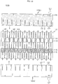
- FIG. 9 is a plane view schematically showing a battery module according to another embodiment of the present disclosure.
- FIG. 10 is an exploded plane view schematically showing components of the battery module according to another embodiment of the present disclosure in a separated state.
- the secondary battery 110 depicted in FIGS. 9 and 10 is identical to the secondary battery 110 of FIG. 2 described above, and thus the secondary battery 110 depicted in FIGS. 9 and 10 will not be described in detail again.
- the arrangement of the plurality of secondary batteries 110 shown in FIG. 9 is different from the arrangement of the plurality of secondary batteries 110 shown in FIG. 2 . That is, all of the plurality of secondary batteries 110 of the battery module 100 may be arranged such that the first electrode leads 111A are located at one side and the second electrode leads 111B are located at the other side.
- the plurality of secondary batteries 110 of the battery module 100B may be arranged such that the first electrode leads 111A (the positive electrode leads) are positioned at one side (a right side) with respect to the center line P of the battery module 100B in the front and rear direction and the second electrode leads 111B (the negative electrode leads) are positioned at the other side (a left side) with respect to the center line P of the battery module 100B in the front and rear direction.
- the battery module 100B may include a first bus bar 120D1 and a second bus bar 120D2 configured to electrically connect the first electrode leads 111A or the second electrode leads 111B of the plurality of secondary batteries 110.
- the battery module 100B may include a first bus bar 120D1 and a second bus bar 120D2.
- the first bus bar 120D1 located at one side (a right side) with respect to the center line P of the battery module 100B may be configured such that the bodies 111a of twelve first electrode leads 111A are inserted into twelve slits 122 formed at the first bus bar 120D1, so as to be electrically connected to the twelve first electrode leads 111A.
- the second bus bar 120D2 located at the other side (a left side) with respect to the center line P of the battery module 100B may be configured such that the bodies 111a of the twelve electrode leads 111B are respectively inserted into the twelve slits 122 formed at the second bus bar 120D2, so as to be electrically connected to the twelve second electrode leads 111B.
- the first bus bar 120D1 may include the same material as the first electrode leads 111A of the plurality of secondary batteries 110.
- the first bus bar 120D1 may include the same aluminum material as the first electrode lead 111A.
- the second bus bar 120D2 may include the same material as the second electrode leads 111B of the plurality of secondary batteries 110.
- the second bus bar 120D2 may include the same copper material as the second electrode lead 111B.
- the external input/output terminal 127 may be formed at each of the first bus bar 120D1 and the second bus bar 120D2.
- the upward extending portion 126 is formed at each of the first bus bar 120D1 and the second bus bar 120D2, and the bolt-type external input/output terminal 127 may be inserted into and fixed to the upward extending portion 126.
- the plurality of secondary batteries 110 may be arranged to be stacked in one direction (a front and rear direction).
- an adhesive or double-sided adhesive tape 140 may be added between the plurality of secondary batteries 110 so that the plurality of secondary batteries 110 are bonded to each other.
- the adhesive or double-sided adhesive tape 140 may include a material with high thermal conductivity.
- the adhesive or double-sided adhesive tape 140 is added between the plurality of secondary batteries 110, it is easy to handle the plurality of secondary batteries 110 in one unit, and a gap is not generated between the plurality of secondary batteries 110 due to the added adhesive or double-sided adhesive tape 140, thereby preventing heat condensation from occurring therein due to the air formed in the gap. Further, if the thermally conductive material is included in the adhesive or double-sided adhesive tape 140, the cooling efficiency of the battery module 100B may be further increased.
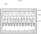
- FIG. 11 is a plane view schematically showing a battery module according to still another embodiment of the present disclosure.
- the battery module 100C may further include a module case 130 having an inner space formed therein to accommodate the plurality of secondary batteries 110.
- the module case 130 may have a rectangular box shape with an open top.
- the plurality of secondary batteries 110 and the plurality of bus bars 120 may be accommodated in the inner space of the module case 130.
- the module case 130 may be filled with a thermally conductive resin 150 to surround the outer surface of the plurality of secondary batteries 110.
- the thermally conductive resin 150 may include a silicon-based resin, a modified silicone resin, or an acrylic resin.
- the thermally conductive resin 150 is filled in the module case 130, it is possible to effectively transfer the heat generated from the plurality of secondary batteries 110 to the module case 130, thereby effectively enhancing the cooling efficiency of the battery module 100C.
- a battery pack (not shown) according to the present disclosure may include at least one battery module 100 according to the present disclosure. Also, the battery pack according to the present disclosure may further include a pack case for accommodating the battery module 100, and various devices for controlling the charge and discharge of the battery module 100, such as a battery management system (BMS), a current sensor and a fuse, in addition to the battery module 100.
- BMS battery management system
- the battery pack according to the present disclosure may be applied to a moving means such as a vehicle.
- a moving means such as a vehicle.
- an electric vehicle according to the present disclosure may include the battery pack according to the present disclosure.
- battery module 110 secondary battery 111: electrode lead 111a : body 111b: head 120: bus bar 122: slit 124: plate portion 126: upward extending portion 130: module case 140: double-sided adhesive tape 150: thermally conductive resin
- the present disclosure relates to a battery module and a battery pack, which includes a secondary battery and a bus bar.
- the present disclosure is available for industries related to electronic devices or vehicles equipped with the battery pack.
Landscapes
- Chemical & Material Sciences (AREA)
- Chemical Kinetics & Catalysis (AREA)
- Electrochemistry (AREA)
- General Chemical & Material Sciences (AREA)
- Engineering & Computer Science (AREA)
- Manufacturing & Machinery (AREA)
- Aviation & Aerospace Engineering (AREA)
- Connection Of Batteries Or Terminals (AREA)
- Battery Mounting, Suspending (AREA)
- Sealing Battery Cases Or Jackets (AREA)
Applications Claiming Priority (2)
| Application Number | Priority Date | Filing Date | Title |
|---|---|---|---|
| KR1020180072154A KR102523098B1 (ko) | 2018-06-22 | 2018-06-22 | 이차 전지 및 이를 포함한 배터리 모듈 |
| PCT/KR2019/007010 WO2019245214A1 (fr) | 2018-06-22 | 2019-06-11 | Module de batterie comprenant une batterie secondaire et une barre omnibus |
Publications (3)
| Publication Number | Publication Date |
|---|---|
| EP3736883A1 true EP3736883A1 (fr) | 2020-11-11 |
| EP3736883A4 EP3736883A4 (fr) | 2021-04-14 |
| EP3736883B1 EP3736883B1 (fr) | 2025-07-30 |
Family
ID=68983690
Family Applications (1)
| Application Number | Title | Priority Date | Filing Date |
|---|---|---|---|
| EP19822155.8A Active EP3736883B1 (fr) | 2018-06-22 | 2019-06-11 | Module de batterie comprenant une batterie secondaire et une barre omnibus |
Country Status (8)
| Country | Link |
|---|---|
| US (2) | US11626640B2 (fr) |
| EP (1) | EP3736883B1 (fr) |
| JP (1) | JP7047220B2 (fr) |
| KR (2) | KR102523098B1 (fr) |
| CN (2) | CN111527626B (fr) |
| ES (1) | ES3037784T3 (fr) |
| HU (1) | HUE072592T2 (fr) |
| WO (1) | WO2019245214A1 (fr) |
Families Citing this family (13)
| Publication number | Priority date | Publication date | Assignee | Title |
|---|---|---|---|---|
| KR102523098B1 (ko) * | 2018-06-22 | 2023-04-17 | 주식회사 엘지에너지솔루션 | 이차 전지 및 이를 포함한 배터리 모듈 |
| CN111180649B (zh) * | 2019-12-30 | 2021-06-11 | 合肥国轩高科动力能源有限公司 | 一体式高温分解接插件及含有该接插件的锂离子电池 |
| KR102886187B1 (ko) * | 2020-09-08 | 2025-11-13 | 주식회사 엘지에너지솔루션 | 전극 리드가 비대칭 구조로 형성된 전지 셀 및 이를 포함하는 기계적 강도가 보강된 전지 모듈 |
| KR20220041470A (ko) | 2020-09-25 | 2022-04-01 | 현대자동차주식회사 | 배터리 모듈 및 이를 포함하는 배터리 팩 |
| KR102708662B1 (ko) * | 2020-12-07 | 2024-09-20 | 주식회사 엘지에너지솔루션 | 배터리 모듈, 배터리 팩, 및 자동차 |
| CN112599933B (zh) * | 2020-12-17 | 2022-03-18 | 合肥国轩高科动力能源有限公司 | 锂电池的多卷芯并联装配方法 |
| CN114883754B (zh) * | 2021-02-05 | 2024-09-20 | 奥迪股份公司 | 汇流排以及相应的电池系统和车辆 |
| CN215119169U (zh) * | 2021-05-19 | 2021-12-10 | 上海峰飞航空科技有限公司 | 一种电池极耳连接结构及电池包 |
| KR102915631B1 (ko) * | 2022-11-17 | 2026-01-21 | 주식회사 엘지에너지솔루션 | 상하단 분리형 버스바프레임을 포함하는 배터리 모듈 및 이를 조립하는 방법 |
| WO2024112184A1 (fr) * | 2022-11-25 | 2024-05-30 | 주식회사 엘지에너지솔루션 | Module de batterie et bloc-batterie le comprenant |
| JP2025537977A (ja) * | 2022-12-02 | 2025-11-20 | エルジー エナジー ソリューション リミテッド | バッテリーパックおよびその製造方法 |
| KR20240128468A (ko) * | 2023-02-17 | 2024-08-26 | 에스케이온 주식회사 | 배터리 셀, 배터리모듈 및 배터리모듈의 제조방법 |
| KR20240128476A (ko) | 2023-02-17 | 2024-08-26 | 에스케이온 주식회사 | 배터리모듈 및 배터리모듈의 제조방법 |
Family Cites Families (20)
| Publication number | Priority date | Publication date | Assignee | Title |
|---|---|---|---|---|
| JPH09213299A (ja) * | 1996-01-31 | 1997-08-15 | Toyota Autom Loom Works Ltd | 蓄電池の集電構造 |
| JP4984366B2 (ja) | 2001-09-27 | 2012-07-25 | ソニー株式会社 | 電池収納パック、これに用いられる電池保護素子を有する接続体及び電池収納パックの製造方法 |
| JP4617672B2 (ja) | 2003-12-26 | 2011-01-26 | トヨタ自動車株式会社 | ラミネート電池モジュールとその製造方法 |
| KR100696793B1 (ko) * | 2005-05-04 | 2007-03-19 | 삼성에스디아이 주식회사 | 리드 플레이트 및 이를 구비하는 캔형 이차 전지 |
| US8088516B2 (en) | 2005-11-18 | 2012-01-03 | Acme Aerospace, Inc. | Storage battery electrodes with integral conductors |
| CN101521294B (zh) * | 2008-10-10 | 2011-05-18 | 比亚迪股份有限公司 | 一种电动汽车用动力电池 |
| JP5287160B2 (ja) * | 2008-11-13 | 2013-09-11 | 株式会社デンソー | バスバー、及びこれを内蔵した電力変換装置 |
| JP2013118115A (ja) * | 2011-12-05 | 2013-06-13 | Sumitomo Electric Ind Ltd | 組電池の電極集電部構造及び該電極集電部構造を有する組電池 |
| JP6313227B2 (ja) | 2012-04-16 | 2018-04-18 | エルジー・ケム・リミテッド | 互いに異なる形状の正極及び負極を含む電極組立体及び二次電池 |
| KR102143624B1 (ko) | 2014-01-08 | 2020-08-11 | 삼성에스디아이 주식회사 | 이차 전지 |
| JP6210314B2 (ja) | 2014-02-12 | 2017-10-11 | 株式会社オートネットワーク技術研究所 | 接続用部材および蓄電モジュール |
| KR101669123B1 (ko) * | 2014-03-03 | 2016-10-25 | 주식회사 엘지화학 | 파우치형 이차 전지 및 이를 포함하는 배터리 모듈 |
| KR101821378B1 (ko) | 2014-03-31 | 2018-01-23 | 주식회사 엘지화학 | 전극 리드와 버스바 사이의 결합력 및 공정성이 향상된 배터리 모듈 및 이를 포함하는 배터리 팩 |
| KR102306442B1 (ko) * | 2014-08-25 | 2021-09-28 | 삼성에스디아이 주식회사 | 전지 모듈 |
| JP6300034B2 (ja) | 2015-03-19 | 2018-03-28 | 株式会社オートネットワーク技術研究所 | 蓄電モジュール |
| CN104882584A (zh) * | 2015-04-21 | 2015-09-02 | 超威电源有限公司 | 一种铅酸蓄电池及电动车 |
| US10644276B2 (en) | 2016-02-11 | 2020-05-05 | Lg Chem, Ltd. | Battery module |
| KR101730576B1 (ko) * | 2016-06-17 | 2017-04-26 | 주식회사 엘지화학 | 배터리 셀 및 이를 포함하는 배터리 모듈 |
| CN205985463U (zh) * | 2016-08-19 | 2017-02-22 | 宝亨新电气(集团)有限公司 | 一种密集型母线槽插口分接桩头 |
| KR102523098B1 (ko) * | 2018-06-22 | 2023-04-17 | 주식회사 엘지에너지솔루션 | 이차 전지 및 이를 포함한 배터리 모듈 |
-
2018
- 2018-06-22 KR KR1020180072154A patent/KR102523098B1/ko active Active
-
2019
- 2019-06-11 WO PCT/KR2019/007010 patent/WO2019245214A1/fr not_active Ceased
- 2019-06-11 JP JP2020539215A patent/JP7047220B2/ja active Active
- 2019-06-11 ES ES19822155T patent/ES3037784T3/es active Active
- 2019-06-11 CN CN201980006962.9A patent/CN111527626B/zh active Active
- 2019-06-11 EP EP19822155.8A patent/EP3736883B1/fr active Active
- 2019-06-11 HU HUE19822155A patent/HUE072592T2/hu unknown
- 2019-06-11 CN CN202311166153.9A patent/CN117199719A/zh active Pending
- 2019-06-11 US US16/961,442 patent/US11626640B2/en active Active
-
2023
- 2023-03-22 US US18/124,885 patent/US12100849B2/en active Active
- 2023-04-07 KR KR1020230046276A patent/KR102619201B1/ko active Active
Also Published As
| Publication number | Publication date |
|---|---|
| ES3037784T3 (en) | 2025-10-06 |
| KR20230051461A (ko) | 2023-04-18 |
| KR102619201B1 (ko) | 2023-12-27 |
| JP7047220B2 (ja) | 2022-04-05 |
| US20210083244A1 (en) | 2021-03-18 |
| JP2021511633A (ja) | 2021-05-06 |
| US12100849B2 (en) | 2024-09-24 |
| EP3736883B1 (fr) | 2025-07-30 |
| CN111527626B (zh) | 2023-09-26 |
| US11626640B2 (en) | 2023-04-11 |
| CN117199719A (zh) | 2023-12-08 |
| HUE072592T2 (hu) | 2025-11-28 |
| CN111527626A (zh) | 2020-08-11 |
| KR102523098B1 (ko) | 2023-04-17 |
| US20230231244A1 (en) | 2023-07-20 |
| WO2019245214A1 (fr) | 2019-12-26 |
| KR20200000181A (ko) | 2020-01-02 |
| EP3736883A4 (fr) | 2021-04-14 |
Similar Documents
| Publication | Publication Date | Title |
|---|---|---|
| US12100849B2 (en) | Battery module including secondary battery and bus bar | |
| US11594776B2 (en) | Battery module including heat shrinkable tube | |
| EP3343691B1 (fr) | Module de batterie | |
| KR101821378B1 (ko) | 전극 리드와 버스바 사이의 결합력 및 공정성이 향상된 배터리 모듈 및 이를 포함하는 배터리 팩 | |
| KR102059077B1 (ko) | 배터리 모듈 및 이를 포함하는 배터리 팩, 자동차 | |
| KR101509474B1 (ko) | 단일 전극단자 결합부를 가진 전지 조합체 | |
| US20200411832A1 (en) | Battery Module Having Bus Bar Assembly | |
| US11984612B2 (en) | Battery module comprising module housing | |
| US12230819B2 (en) | Battery module and battery pack including the same | |
| US20200044224A1 (en) | Battery module | |
| KR102214538B1 (ko) | 단위전지모듈 및 이를 포함하는 전지모듈 | |
| US20230299431A1 (en) | Battery cell, battery module, and battery pack including the same | |
| CN113939946A (zh) | 电池模块和包括该电池模块的电池组 | |
| KR20150033176A (ko) | 배터리 모듈 및 이에 적용되는 버스바 | |
| US12482877B2 (en) | Battery module and battery pack including the same | |
| EP4693657A1 (fr) | Bloc-batterie et dispositif le comprenant | |
| KR20250024495A (ko) | 전지 팩 및 이를 포함하는 디바이스 |
Legal Events
| Date | Code | Title | Description |
|---|---|---|---|
| STAA | Information on the status of an ep patent application or granted ep patent |
Free format text: STATUS: THE INTERNATIONAL PUBLICATION HAS BEEN MADE |
|
| PUAI | Public reference made under article 153(3) epc to a published international application that has entered the european phase |
Free format text: ORIGINAL CODE: 0009012 |
|
| STAA | Information on the status of an ep patent application or granted ep patent |
Free format text: STATUS: REQUEST FOR EXAMINATION WAS MADE |
|
| 17P | Request for examination filed |
Effective date: 20200805 |
|
| AK | Designated contracting states |
Kind code of ref document: A1 Designated state(s): AL AT BE BG CH CY CZ DE DK EE ES FI FR GB GR HR HU IE IS IT LI LT LU LV MC MK MT NL NO PL PT RO RS SE SI SK SM TR |
|
| AX | Request for extension of the european patent |
Extension state: BA ME |
|
| REG | Reference to a national code |
Ref country code: DE Free format text: PREVIOUS MAIN CLASS: H01M0002260000 Ref country code: DE Ref legal event code: R079 Ref document number: 602019073367 Country of ref document: DE Free format text: PREVIOUS MAIN CLASS: H01M0002260000 Ipc: H01M0050200000 |
|
| A4 | Supplementary search report drawn up and despatched |
Effective date: 20210312 |
|
| RIC1 | Information provided on ipc code assigned before grant |
Ipc: H01M 50/20 20210101AFI20210308BHEP Ipc: H01M 50/50 20210101ALI20210308BHEP Ipc: H01M 50/531 20210101ALI20210308BHEP Ipc: H01M 50/533 20210101ALI20210308BHEP Ipc: H01M 50/543 20210101ALI20210308BHEP Ipc: H01M 50/557 20210101ALI20210308BHEP |
|
| DAV | Request for validation of the european patent (deleted) | ||
| DAX | Request for extension of the european patent (deleted) | ||
| RAP1 | Party data changed (applicant data changed or rights of an application transferred) |
Owner name: LG ENERGY SOLUTION LTD. |
|
| RAP3 | Party data changed (applicant data changed or rights of an application transferred) |
Owner name: LG ENERGY SOLUTION, LTD. |
|
| STAA | Information on the status of an ep patent application or granted ep patent |
Free format text: STATUS: EXAMINATION IS IN PROGRESS |
|
| 17Q | First examination report despatched |
Effective date: 20230512 |
|
| REG | Reference to a national code |
Ref country code: DE Ref legal event code: R079 Free format text: PREVIOUS MAIN CLASS: H01M0050200000 Ipc: H01M0050211000 Ref country code: DE Ref legal event code: R079 Ref document number: 602019073367 Country of ref document: DE Free format text: PREVIOUS MAIN CLASS: H01M0050200000 Ipc: H01M0050211000 |
|
| GRAP | Despatch of communication of intention to grant a patent |
Free format text: ORIGINAL CODE: EPIDOSNIGR1 |
|
| STAA | Information on the status of an ep patent application or granted ep patent |
Free format text: STATUS: GRANT OF PATENT IS INTENDED |
|
| RIC1 | Information provided on ipc code assigned before grant |
Ipc: H01M 50/557 20210101ALI20250319BHEP Ipc: H01M 50/553 20210101ALI20250319BHEP Ipc: H01M 50/533 20210101ALI20250319BHEP Ipc: H01M 50/178 20210101ALI20250319BHEP Ipc: H01M 50/50 20210101ALI20250319BHEP Ipc: H01M 50/211 20210101AFI20250319BHEP |
|
| INTG | Intention to grant announced |
Effective date: 20250404 |
|
| GRAS | Grant fee paid |
Free format text: ORIGINAL CODE: EPIDOSNIGR3 |
|
| P01 | Opt-out of the competence of the unified patent court (upc) registered |
Free format text: CASE NUMBER: APP_21306/2025 Effective date: 20250506 |
|
| GRAA | (expected) grant |
Free format text: ORIGINAL CODE: 0009210 |
|
| STAA | Information on the status of an ep patent application or granted ep patent |
Free format text: STATUS: THE PATENT HAS BEEN GRANTED |
|
| AK | Designated contracting states |
Kind code of ref document: B1 Designated state(s): AL AT BE BG CH CY CZ DE DK EE ES FI FR GB GR HR HU IE IS IT LI LT LU LV MC MK MT NL NO PL PT RO RS SE SI SK SM TR |
|
| REG | Reference to a national code |
Ref country code: GB Ref legal event code: FG4D |
|
| REG | Reference to a national code |
Ref country code: CH Ref legal event code: EP |
|
| REG | Reference to a national code |
Ref country code: DE Ref legal event code: R096 Ref document number: 602019073367 Country of ref document: DE |
|
| REG | Reference to a national code |
Ref country code: IE Ref legal event code: FG4D |
|
| REG | Reference to a national code |
Ref country code: ES Ref legal event code: FG2A Ref document number: 3037784 Country of ref document: ES Kind code of ref document: T3 Effective date: 20251006 |
|
| REG | Reference to a national code |
Ref country code: HU Ref legal event code: AG4A Ref document number: E072592 Country of ref document: HU |
|
| REG | Reference to a national code |
Ref country code: NL Ref legal event code: MP Effective date: 20250730 |
|
| REG | Reference to a national code |
Ref country code: AT Ref legal event code: MK05 Ref document number: 1820063 Country of ref document: AT Kind code of ref document: T Effective date: 20250730 |
|
| PG25 | Lapsed in a contracting state [announced via postgrant information from national office to epo] |
Ref country code: PT Free format text: LAPSE BECAUSE OF FAILURE TO SUBMIT A TRANSLATION OF THE DESCRIPTION OR TO PAY THE FEE WITHIN THE PRESCRIBED TIME-LIMIT Effective date: 20251202 |
|
| PG25 | Lapsed in a contracting state [announced via postgrant information from national office to epo] |
Ref country code: IS Free format text: LAPSE BECAUSE OF FAILURE TO SUBMIT A TRANSLATION OF THE DESCRIPTION OR TO PAY THE FEE WITHIN THE PRESCRIBED TIME-LIMIT Effective date: 20251130 |
|
| PG25 | Lapsed in a contracting state [announced via postgrant information from national office to epo] |
Ref country code: NO Free format text: LAPSE BECAUSE OF FAILURE TO SUBMIT A TRANSLATION OF THE DESCRIPTION OR TO PAY THE FEE WITHIN THE PRESCRIBED TIME-LIMIT Effective date: 20251030 |
|
| REG | Reference to a national code |
Ref country code: LT Ref legal event code: MG9D |
|
| PG25 | Lapsed in a contracting state [announced via postgrant information from national office to epo] |
Ref country code: AT Free format text: LAPSE BECAUSE OF FAILURE TO SUBMIT A TRANSLATION OF THE DESCRIPTION OR TO PAY THE FEE WITHIN THE PRESCRIBED TIME-LIMIT Effective date: 20250730 |
|
| PG25 | Lapsed in a contracting state [announced via postgrant information from national office to epo] |
Ref country code: FI Free format text: LAPSE BECAUSE OF FAILURE TO SUBMIT A TRANSLATION OF THE DESCRIPTION OR TO PAY THE FEE WITHIN THE PRESCRIBED TIME-LIMIT Effective date: 20250730 |
|
| PG25 | Lapsed in a contracting state [announced via postgrant information from national office to epo] |
Ref country code: NL Free format text: LAPSE BECAUSE OF FAILURE TO SUBMIT A TRANSLATION OF THE DESCRIPTION OR TO PAY THE FEE WITHIN THE PRESCRIBED TIME-LIMIT Effective date: 20250730 Ref country code: HR Free format text: LAPSE BECAUSE OF FAILURE TO SUBMIT A TRANSLATION OF THE DESCRIPTION OR TO PAY THE FEE WITHIN THE PRESCRIBED TIME-LIMIT Effective date: 20250730 |
|
| PG25 | Lapsed in a contracting state [announced via postgrant information from national office to epo] |
Ref country code: GR Free format text: LAPSE BECAUSE OF FAILURE TO SUBMIT A TRANSLATION OF THE DESCRIPTION OR TO PAY THE FEE WITHIN THE PRESCRIBED TIME-LIMIT Effective date: 20251031 |
|
| PG25 | Lapsed in a contracting state [announced via postgrant information from national office to epo] |
Ref country code: SE Free format text: LAPSE BECAUSE OF FAILURE TO SUBMIT A TRANSLATION OF THE DESCRIPTION OR TO PAY THE FEE WITHIN THE PRESCRIBED TIME-LIMIT Effective date: 20250730 |
|
| PG25 | Lapsed in a contracting state [announced via postgrant information from national office to epo] |
Ref country code: LV Free format text: LAPSE BECAUSE OF FAILURE TO SUBMIT A TRANSLATION OF THE DESCRIPTION OR TO PAY THE FEE WITHIN THE PRESCRIBED TIME-LIMIT Effective date: 20250730 |
|
| PG25 | Lapsed in a contracting state [announced via postgrant information from national office to epo] |
Ref country code: BG Free format text: LAPSE BECAUSE OF FAILURE TO SUBMIT A TRANSLATION OF THE DESCRIPTION OR TO PAY THE FEE WITHIN THE PRESCRIBED TIME-LIMIT Effective date: 20250730 Ref country code: PL Free format text: LAPSE BECAUSE OF FAILURE TO SUBMIT A TRANSLATION OF THE DESCRIPTION OR TO PAY THE FEE WITHIN THE PRESCRIBED TIME-LIMIT Effective date: 20250730 |
|
| PG25 | Lapsed in a contracting state [announced via postgrant information from national office to epo] |
Ref country code: RS Free format text: LAPSE BECAUSE OF FAILURE TO SUBMIT A TRANSLATION OF THE DESCRIPTION OR TO PAY THE FEE WITHIN THE PRESCRIBED TIME-LIMIT Effective date: 20251030 |
|
| PG25 | Lapsed in a contracting state [announced via postgrant information from national office to epo] |
Ref country code: SM Free format text: LAPSE BECAUSE OF FAILURE TO SUBMIT A TRANSLATION OF THE DESCRIPTION OR TO PAY THE FEE WITHIN THE PRESCRIBED TIME-LIMIT Effective date: 20250730 |
|
| PG25 | Lapsed in a contracting state [announced via postgrant information from national office to epo] |
Ref country code: DK Free format text: LAPSE BECAUSE OF FAILURE TO SUBMIT A TRANSLATION OF THE DESCRIPTION OR TO PAY THE FEE WITHIN THE PRESCRIBED TIME-LIMIT Effective date: 20250730 |
|
| PG25 | Lapsed in a contracting state [announced via postgrant information from national office to epo] |
Ref country code: IT Free format text: LAPSE BECAUSE OF FAILURE TO SUBMIT A TRANSLATION OF THE DESCRIPTION OR TO PAY THE FEE WITHIN THE PRESCRIBED TIME-LIMIT Effective date: 20250730 |