EP3737082A1 - Procédé de commande de panoramique horizontal-vertical, panoramique horizontal-vertical et support d'informations lisible par machine - Google Patents
Procédé de commande de panoramique horizontal-vertical, panoramique horizontal-vertical et support d'informations lisible par machine Download PDFInfo
- Publication number
- EP3737082A1 EP3737082A1 EP18898954.5A EP18898954A EP3737082A1 EP 3737082 A1 EP3737082 A1 EP 3737082A1 EP 18898954 A EP18898954 A EP 18898954A EP 3737082 A1 EP3737082 A1 EP 3737082A1
- Authority
- EP
- European Patent Office
- Prior art keywords
- follow
- gimbal
- rotation axis
- speed
- target object
- Prior art date
- Legal status (The legal status is an assumption and is not a legal conclusion. Google has not performed a legal analysis and makes no representation as to the accuracy of the status listed.)
- Withdrawn
Links
- 238000000034 method Methods 0.000 title claims abstract description 69
- 230000001960 triggered effect Effects 0.000 claims abstract description 21
- 238000005259 measurement Methods 0.000 claims description 7
- 206010034719 Personality change Diseases 0.000 claims description 4
- 230000008569 process Effects 0.000 description 24
- 230000008859 change Effects 0.000 description 9
- 238000010586 diagram Methods 0.000 description 5
- 230000001133 acceleration Effects 0.000 description 4
- 230000007246 mechanism Effects 0.000 description 2
- 238000005070 sampling Methods 0.000 description 2
- 238000013459 approach Methods 0.000 description 1
- 238000011161 development Methods 0.000 description 1
- 230000003287 optical effect Effects 0.000 description 1
- 238000012545 processing Methods 0.000 description 1
- 230000004044 response Effects 0.000 description 1
- 239000002699 waste material Substances 0.000 description 1
Images


Classifications
-
- G—PHYSICS
- G03—PHOTOGRAPHY; CINEMATOGRAPHY; ANALOGOUS TECHNIQUES USING WAVES OTHER THAN OPTICAL WAVES; ELECTROGRAPHY; HOLOGRAPHY
- G03B—APPARATUS OR ARRANGEMENTS FOR TAKING PHOTOGRAPHS OR FOR PROJECTING OR VIEWING THEM; APPARATUS OR ARRANGEMENTS EMPLOYING ANALOGOUS TECHNIQUES USING WAVES OTHER THAN OPTICAL WAVES; ACCESSORIES THEREFOR
- G03B17/00—Details of cameras or camera bodies; Accessories therefor
- G03B17/56—Accessories
- G03B17/563—Camera grips, handles
-
- F—MECHANICAL ENGINEERING; LIGHTING; HEATING; WEAPONS; BLASTING
- F16—ENGINEERING ELEMENTS AND UNITS; GENERAL MEASURES FOR PRODUCING AND MAINTAINING EFFECTIVE FUNCTIONING OF MACHINES OR INSTALLATIONS; THERMAL INSULATION IN GENERAL
- F16M—FRAMES, CASINGS OR BEDS OF ENGINES, MACHINES OR APPARATUS, NOT SPECIFIC TO ENGINES, MACHINES OR APPARATUS PROVIDED FOR ELSEWHERE; STANDS; SUPPORTS
- F16M11/00—Stands or trestles as supports for apparatus or articles placed thereon ; Stands for scientific apparatus such as gravitational force meters
- F16M11/02—Heads
- F16M11/04—Means for attachment of apparatus; Means allowing adjustment of the apparatus relatively to the stand
- F16M11/06—Means for attachment of apparatus; Means allowing adjustment of the apparatus relatively to the stand allowing pivoting
- F16M11/08—Means for attachment of apparatus; Means allowing adjustment of the apparatus relatively to the stand allowing pivoting around a vertical axis, e.g. panoramic heads
-
- G—PHYSICS
- G05—CONTROLLING; REGULATING
- G05D—SYSTEMS FOR CONTROLLING OR REGULATING NON-ELECTRIC VARIABLES
- G05D3/00—Control of position or direction
- G05D3/12—Control of position or direction using feedback
-
- F—MECHANICAL ENGINEERING; LIGHTING; HEATING; WEAPONS; BLASTING
- F16—ENGINEERING ELEMENTS AND UNITS; GENERAL MEASURES FOR PRODUCING AND MAINTAINING EFFECTIVE FUNCTIONING OF MACHINES OR INSTALLATIONS; THERMAL INSULATION IN GENERAL
- F16M—FRAMES, CASINGS OR BEDS OF ENGINES, MACHINES OR APPARATUS, NOT SPECIFIC TO ENGINES, MACHINES OR APPARATUS PROVIDED FOR ELSEWHERE; STANDS; SUPPORTS
- F16M11/00—Stands or trestles as supports for apparatus or articles placed thereon ; Stands for scientific apparatus such as gravitational force meters
- F16M11/02—Heads
- F16M11/04—Means for attachment of apparatus; Means allowing adjustment of the apparatus relatively to the stand
- F16M11/06—Means for attachment of apparatus; Means allowing adjustment of the apparatus relatively to the stand allowing pivoting
- F16M11/10—Means for attachment of apparatus; Means allowing adjustment of the apparatus relatively to the stand allowing pivoting around a horizontal axis
-
- F—MECHANICAL ENGINEERING; LIGHTING; HEATING; WEAPONS; BLASTING
- F16—ENGINEERING ELEMENTS AND UNITS; GENERAL MEASURES FOR PRODUCING AND MAINTAINING EFFECTIVE FUNCTIONING OF MACHINES OR INSTALLATIONS; THERMAL INSULATION IN GENERAL
- F16M—FRAMES, CASINGS OR BEDS OF ENGINES, MACHINES OR APPARATUS, NOT SPECIFIC TO ENGINES, MACHINES OR APPARATUS PROVIDED FOR ELSEWHERE; STANDS; SUPPORTS
- F16M11/00—Stands or trestles as supports for apparatus or articles placed thereon ; Stands for scientific apparatus such as gravitational force meters
- F16M11/02—Heads
- F16M11/04—Means for attachment of apparatus; Means allowing adjustment of the apparatus relatively to the stand
- F16M11/06—Means for attachment of apparatus; Means allowing adjustment of the apparatus relatively to the stand allowing pivoting
- F16M11/12—Means for attachment of apparatus; Means allowing adjustment of the apparatus relatively to the stand allowing pivoting in more than one direction
- F16M11/121—Means for attachment of apparatus; Means allowing adjustment of the apparatus relatively to the stand allowing pivoting in more than one direction constituted of several dependent joints
- F16M11/123—Means for attachment of apparatus; Means allowing adjustment of the apparatus relatively to the stand allowing pivoting in more than one direction constituted of several dependent joints the axis of rotation intersecting in a single point, e.g. by using gimbals
-
- F—MECHANICAL ENGINEERING; LIGHTING; HEATING; WEAPONS; BLASTING
- F16—ENGINEERING ELEMENTS AND UNITS; GENERAL MEASURES FOR PRODUCING AND MAINTAINING EFFECTIVE FUNCTIONING OF MACHINES OR INSTALLATIONS; THERMAL INSULATION IN GENERAL
- F16M—FRAMES, CASINGS OR BEDS OF ENGINES, MACHINES OR APPARATUS, NOT SPECIFIC TO ENGINES, MACHINES OR APPARATUS PROVIDED FOR ELSEWHERE; STANDS; SUPPORTS
- F16M11/00—Stands or trestles as supports for apparatus or articles placed thereon ; Stands for scientific apparatus such as gravitational force meters
- F16M11/02—Heads
- F16M11/18—Heads with mechanism for moving the apparatus relatively to the stand
-
- F—MECHANICAL ENGINEERING; LIGHTING; HEATING; WEAPONS; BLASTING
- F16—ENGINEERING ELEMENTS AND UNITS; GENERAL MEASURES FOR PRODUCING AND MAINTAINING EFFECTIVE FUNCTIONING OF MACHINES OR INSTALLATIONS; THERMAL INSULATION IN GENERAL
- F16M—FRAMES, CASINGS OR BEDS OF ENGINES, MACHINES OR APPARATUS, NOT SPECIFIC TO ENGINES, MACHINES OR APPARATUS PROVIDED FOR ELSEWHERE; STANDS; SUPPORTS
- F16M11/00—Stands or trestles as supports for apparatus or articles placed thereon ; Stands for scientific apparatus such as gravitational force meters
- F16M11/20—Undercarriages with or without wheels
- F16M11/2007—Undercarriages with or without wheels comprising means allowing pivoting adjustment
- F16M11/2035—Undercarriages with or without wheels comprising means allowing pivoting adjustment in more than one direction
- F16M11/2071—Undercarriages with or without wheels comprising means allowing pivoting adjustment in more than one direction for panning and rolling
-
- F—MECHANICAL ENGINEERING; LIGHTING; HEATING; WEAPONS; BLASTING
- F16—ENGINEERING ELEMENTS AND UNITS; GENERAL MEASURES FOR PRODUCING AND MAINTAINING EFFECTIVE FUNCTIONING OF MACHINES OR INSTALLATIONS; THERMAL INSULATION IN GENERAL
- F16M—FRAMES, CASINGS OR BEDS OF ENGINES, MACHINES OR APPARATUS, NOT SPECIFIC TO ENGINES, MACHINES OR APPARATUS PROVIDED FOR ELSEWHERE; STANDS; SUPPORTS
- F16M13/00—Other supports for positioning apparatus or articles; Means for steadying hand-held apparatus or articles
-
- F—MECHANICAL ENGINEERING; LIGHTING; HEATING; WEAPONS; BLASTING
- F16—ENGINEERING ELEMENTS AND UNITS; GENERAL MEASURES FOR PRODUCING AND MAINTAINING EFFECTIVE FUNCTIONING OF MACHINES OR INSTALLATIONS; THERMAL INSULATION IN GENERAL
- F16M—FRAMES, CASINGS OR BEDS OF ENGINES, MACHINES OR APPARATUS, NOT SPECIFIC TO ENGINES, MACHINES OR APPARATUS PROVIDED FOR ELSEWHERE; STANDS; SUPPORTS
- F16M2200/00—Details of stands or supports
- F16M2200/04—Balancing means
- F16M2200/041—Balancing means for balancing rotational movement of the head
-
- F—MECHANICAL ENGINEERING; LIGHTING; HEATING; WEAPONS; BLASTING
- F16—ENGINEERING ELEMENTS AND UNITS; GENERAL MEASURES FOR PRODUCING AND MAINTAINING EFFECTIVE FUNCTIONING OF MACHINES OR INSTALLATIONS; THERMAL INSULATION IN GENERAL
- F16M—FRAMES, CASINGS OR BEDS OF ENGINES, MACHINES OR APPARATUS, NOT SPECIFIC TO ENGINES, MACHINES OR APPARATUS PROVIDED FOR ELSEWHERE; STANDS; SUPPORTS
- F16M2200/00—Details of stands or supports
- F16M2200/04—Balancing means
- F16M2200/044—Balancing means for balancing rotational movement of the undercarriage
-
- H—ELECTRICITY
- H04—ELECTRIC COMMUNICATION TECHNIQUE
- H04N—PICTORIAL COMMUNICATION, e.g. TELEVISION
- H04N23/00—Cameras or camera modules comprising electronic image sensors; Control thereof
- H04N23/50—Constructional details
- H04N23/51—Housings
-
- H—ELECTRICITY
- H04—ELECTRIC COMMUNICATION TECHNIQUE
- H04N—PICTORIAL COMMUNICATION, e.g. TELEVISION
- H04N23/00—Cameras or camera modules comprising electronic image sensors; Control thereof
- H04N23/95—Computational photography systems, e.g. light-field imaging systems
- H04N23/951—Computational photography systems, e.g. light-field imaging systems by using two or more images to influence resolution, frame rate or aspect ratio
Definitions
- the present disclosure relates to the field of control, and in particular, to a gimbal control method, a gimbal and a machine-readable storage medium.
- handheld gimbals are becoming more and more popular with users.
- the handheld gimbal In the process of following the target object, the handheld gimbal sometimes needs to respond quickly to the motion of the handle to make the handheld gimbal closely follow the movement of the target object, and sometimes it needs to respond slowly to the motion of the handle to make pictures shot with handheld gimbal smooth.
- the user connects the handheld gimbal from a mobile phone APP via Bluetooth, and then sets the follow parameters such as the speed and acceleration of the handheld gimbal. In this way, the follow parameters of the handheld gimbal for following the target object can be adjusted.
- the present disclosure provides a gimbal control method, a gimbal and a machine-readable storage medium.
- One aspect of the disclosure provides a gimbal control method including detecting whether a follow-configuration button provided at the gimbal is triggered, and adjusting follow parameters of the gimbal for following a target object according to the trigger when the trigger is detected.
- One aspect of the disclosure provides a gimbal including a memory, a processor, and a follow-configuration button.
- the memory is used to store control instructions of the gimbal, wherein the processor calls the control instructions and performs operations including detecting whether the follow-configuration button is triggered and adjusting the follow parameters of the gimbal for following the target object according to the trigger when the trigger is detected.
- One aspect of the disclosure provides a machine-readable storage medium.
- the machine-readable storage medium stores a plurality of computer instructions, and the executed computer instructions perform the method described above.
- the follow speed of the gimbal for following the target object is adjusted when the follow-configuration button provided at the gimbal is triggered, instead of through the mobile APP.
- the follow speed of gimbal for following the target object can be ensured to be adjusted flexibly in the present disclosure.
- the gimbal is used to carry a camera.
- the gimbal can be a two-axis gimbal or a three-axis gimbal.
- FIG. 1 is a structural diagram of a bracket assembly of a three-axis gimbal (labeled as bracket assembly 100).
- the bracket assembly 100 mainly includes a pitch axis motor 101, a roll axis motor 102, a yaw axis motor 103, a gimbal base 104, a yaw axis arm 105, a photographing device fixation mechanism 106 (including an inertial measurement unit (IMU) inside), a pitch axis arm 107, and a roll axis arm 108.
- the photographing device fixation mechanism 106 is used to connect the photographing device 109 to the bracket assembly 100.
- the roll axis arm 108 is used to support the pitch axis arm 107 and the pitch axis motor 101
- the yaw axis arm 105 is used to support the yaw axis motor 103 and the roll axis motor 102
- the pitch axis arm 107 is used to support the photographing device 109.
- An angle sensor and a circuit board can be installed inside the pitch axis motor 101, the roll axis motor 102, and the yaw axis motor 103 (these three motors can be referred to as driving motors).
- the angle sensor can be electrically connected to the circuit board.
- the angle sensor installed at the driving motor can measure the rotation angle of the driving motor.
- the angle sensor can be one or multiple of a potentiometer, a Hall sensor, or an encoder.
- the bracket assembly 100 may be connected to the handle or a mobile platform (not shown in FIG. 1 ) through the gimbal base 104.
- the gimbal mainly uses an inertial measurement unit as a feedback element and uses the driving motors of the gimbal's axes (yaw axis, pitch axis, roll axis) as output elements to form a closed loop control system to control the attitude of the gimbal.
- the control parameter is the attitude of the gimbal.
- the current attitude of the gimbal is corrected to the target attitude through feedback control, so that the gimbal approaches to the target attitude from the current attitude, and finally reaches the target attitude.
- FIG. 2 is a flowchart of a gimbal control method according to embodiment 1 of the disclosure. This process is applied to a handheld gimbal, which includes a handle and a bracket assembly for adjusting the attitude of the gimbal.
- the bracket assembly includes at least one rotation axis.
- the improvements of setting the follow-configuration button at the gimbal is made.
- the follow-configuration button is a physical button.
- the follow-configuration button can be a virtual button displayed on a screen provided at the gimbal.
- the gimbal is a handheld gimbal and includes a handle.
- the number of the physical buttons is at least one and the physical buttons are disposed at the handle.
- the specific position of the follow-configuration button disposed at the handle is not limited in the embodiments of the disclosure.
- the follow-configuration button can be set at a position at the handle that is convenient for a user to operate.
- FIG. 3 illustrates an example of setting a follow-configuration button at the handle.
- the follow parameters of the gimbal for following the target object are adjusted according to the trigger.
- the follow parameters of the gimbal for following the target object are adjusted based on whether the follow-configuration button provided at the gimbal is triggered, instead of through the mobile APP.
- the follow parameters of the gimbal for following the target object can be ensured to be adjusted flexibly in the present disclosure.
- Embodiment 1 is described above.
- FIG. 4 is a flowchart of the gimbal control method according to embodiment 2. As shown in Figure 4 , at 401, whether a follow-configuration button provided at the gimbal is triggered is detected.
- the process of 401 is similar to the process of 201 and is not described again.
- a follow coefficient corresponding to the follow-configuration button after receiving the trigger is determined.
- determining the follow coefficient corresponding to the follow-configuration button after receiving the trigger includes the following.
- a first state of the follow-configuration button before receiving the trigger is identified.
- At least one follow-configuration button can be disposed at the gimbal.
- the follow-configuration button sequentially switches from the first state to a second state according to a specified state cycle order after receiving the trigger.
- the specified state cycle order is middle state-> high state-> low state, and at a1, the first state to which the follow-configuration button corresponds before receiving the trigger is identified as middle state, then when the trigger is received, according to the specified state cycle order as middle state-> high state-> low state, the state of the follow-configuration button will be switched from the currently indicated first state (taking the middle state as an example) to the second state (taking the high state as an example) .
- a follow coefficient corresponding to the second state is determined as the follow coefficient corresponding to the follow-configuration button after receiving the trigger.
- the states corresponding to the follow-configuration buttons are different, and the different states of the follow-configuration buttons correspond to different follow coefficients.
- the follow coefficient corresponding to the second state after the switch is determined as the follow coefficient corresponding to the follow-configuration button after receiving the trigger, and then the follow coefficient corresponding to the second state after switching can be used to adjust the follow parameters of the gimbal for following the target object. Therefore, the follow parameters of the gimbal for following the target object can be adjusted automatically.
- the details are described at 403 below.
- the states corresponding to the follow-configuration buttons are different, and the different states of the follow-configuration buttons correspond to same follow coefficients.
- the follow-configuration button may be again triggered until the follow coefficient corresponding to the state after switching is different from the follow coefficient corresponding to the state before switching. Then the follow coefficient corresponding to the state after switching can be used to adjust the follow parameters of the gimbal for following the target object. Therefore, the follow parameters of the gimbal for following the target object can be adjusted automatically. The details are described at 403 below.
- the follow-configuration button may not be triggered again. Instead, the follow parameters before switching can be directly used to control the gimbal to follow the target object.
- the follow parameters of the gimbal for following the target object is adjusted according to the follow coefficient.
- the follow parameters of the gimbal for following the target object are adjusted based on whether the follow-configuration button provided at the gimbal is triggered, instead of through the mobile APP.
- the follow parameters of the gimbal for following the target object can be ensured to be adjusted flexibly in the present disclosure.
- Embodiment 2 is described above.
- FIG. 5 is a flowchart of the gimbal control method according to embodiment 3.
- a follow speed is used as the follow parameter to describe how to implement the gimbal control.
- the process of 501 is similar to the process of 201 and is not described again.
- a follow coefficient corresponding to the follow-configuration button after receiving the trigger is determined.
- the process of 502 is similar to the process of 402 and is not described again.
- the follow coefficients determined at 502 include a follow speed coefficient.
- the follow speed coefficients include follow speed coefficients corresponding to different rotation axes and the follow speed coefficients corresponding to different rotation axes are the same or different.
- the follow speed coefficient can be pre-configured through an application program (APP). The pre-configured follow speed coefficient can be adaptively adjusted according to requirements and is not fixed.
- the follow coefficient may further include a follow identifier.
- the follow identifier may be pre-configured through an APP.
- the follow identifiers corresponding to different rotation axes can be set separately. For example, the follow identifier corresponding to the roll axis is the first identifier representing to follow, the follow identifier corresponding to the yaw axis is the second identifier representing not to follow, and the follow identifier corresponding to the pitch axis is the first identifier representing to follow.
- 503 may further include determining the follow identifier corresponding to each rotation axis and, when the follow identifier corresponding to a rotation axis is the first identifier representing to follow, performing the processes at 503 to 504 for the rotation axis. That is, the processes at 503 and 504 are performed for a rotation axis whose corresponding follow identifier is the first identifier representing to follow.
- the states corresponding to the follow-configuration buttons are different, and the follow identifiers of the follow coefficients corresponding to different states may also be different.
- the three different states are low state, middle state, and high state.
- the follow coefficients corresponding to the low state include the follow identifier corresponding to the pitch axis that is the second identifier representing not to follow, and the follow identifiers corresponding to the remaining two rotation axes (roll axis, yaw axis) that are the first identifier representing to follow, which means that only the roll axis and yaw axis follow.
- the follow coefficients corresponding to the middle state include the follow identifier corresponding to the roll axis that is the second identifier representing not to follow, and the follow identifier corresponding to the remaining two rotation axes (roll axis, pitch axis) that are the first identifier representing to follow, which means that only the roll axis and pitch axis follow.
- the follow coefficients corresponding to the high state include the follow identifiers corresponding to the pitch axis, the roll axis, and the yaw axis that are the first identifier representing to follow, which means that the pitch axis, the roll axis, and the yaw axis all follow.
- the follow identifiers in the follow coefficients corresponding to different states may be specifically set according to actual needs and are not limited in the embodiments of the disclosure.
- the follow coefficients that can also be set for a certain state include the follow identifiers corresponding to the pitch axis, roll axis, and yaw axis that are the second identifier representing not to follow. In this case, there is no need to follow. The follow mode is stopped, and a free mode is switched to.
- the gimbal includes at least one rotation axis such as a pitch axis, a roll axis, and a yaw axis for adjusting the attitude of the gimbal.
- a first difference value is obtained by calculating the difference between the handle attitude information and the gimbal target attitude information along the rotation axis.
- the handle attitude information along the rotation axis includes a Euler angle of the handle along the rotation axis.
- the Euler angle of the handle along the rotation axis includes the Euler angle of the handle along the rotation axis obtained by converting the attitude quaternion of the handle along the rotation axis, which is obtained by rotating the attitude quaternion of the inertial measurement element (IMU) itself around the rotation axis of the gimbal.
- IMU inertial measurement element
- a quaternion is a mathematical representation of an attitude.
- q is expressed as (S, V), where S represents the scalar w and V represents the vector xi + yj + zk.
- the gimbal target attitude information along the rotation axis includes determining the gimbal target attitude information along the rotation axis according to the follow speed of the gimbal for following the target object along the rotation axis after receiving the trigger.
- determining the gimbal target attitude information along the rotation axis according to the follow speed of the gimbal for following the target object along the rotation axis when receiving the trigger may include obtaining the gimbal target attitude information along the rotation axis by integrating the follow speed of the gimbal for following the target object along the rotation axis after receiving the trigger.
- the obtained gimbal target attitude information is also an angle.
- a first difference value is obtained by calculating the difference between the handle attitude information along the rotation axis and the gimbal target attitude information.
- the follow speed of the gimbal for following the target object along the rotation axis is calculated according to the first difference value and the follow speed coefficient corresponding to the rotation axis.
- calculating the follow speed of the gimbal for following the target object along the rotation axis according to the first difference value and the follow speed coefficient corresponding to the rotation axis may be implemented by the following formula:
- follow_speed (atti_handler - atti_target) ⁇ speed_coef/freq, where, follow_speed represents the follow speed along the rotation axis, handler atti represents the handle attitude information along the rotation axis; atti target represents the gimbal target attitude information along the rotation axis; atti_handler-atti_target is the first difference value, speed coef represents the follow speed coefficient corresponding to the rotation axis, and freq is a pre-configured frequency, specifically the frequency of IMU sampling.
- the follow speed of the gimbal for following the target object along the rotation axis can be calculated.
- the gimbal can be controlled to follow the target object along the rotation axis according to the calculated follow speed of the gimbal for following the target object along the rotation axis. The details are described at 505.
- the gimbal is controlled to follow the target object along the rotation axis according to the follow speed.
- the follow speed of the gimbal for following the target object along the rotation axis is essentially the speed at which a photographing device at the gimbal, such as the photographing device 109 shown in FIG. 1 , responds to a change in attitude of the rotation axis.
- the absolute value of the follow speed calculated at 504 is greater than 0, it means that the photographing device at the gimbal, such as the photographing device 109 shown in FIG. 1 , responds to the change in attitude of the rotation axis according to the calculated follow speed to better follow the target object.
- the follow speed calculated at 504 is equal to 0, it means that the attitude of the rotation axis is close to the target attitude at this time, and the responding speed of the photographing device at the gimbal, such as the photographing device 109 shown in FIG. 1 , to the change in attitude of the rotation axis is close to 0. That is, the photographing device at the gimbal, such as the photographing device 109 shown in FIG. 1 , is controlled to stop following the change in attitude of the rotation axis.
- processes from 502 to 505 are used to implement the adjustment of the follow parameters of the gimbal for following the target object according to the trigger at 202.
- the follow speed of the gimbal for following the target object is adjusted based on whether the follow-configuration button provided at the gimbal is triggered, instead of through the mobile APP.
- the follow speed of the gimbal for following the target object can be ensured to be adjusted flexibly in the present disclosure.
- Embodiment 3 is described above.
- FIG. 6 is a flowchart of the gimbal control method according to embodiment 4. As shown in FIG.6 , at 601, whether a follow-configuration button provided at the gimbal is triggered is detected.
- the process of 601 is similar to the process of 201 and is not described again.
- a follow coefficient corresponding to the follow-configuration button after receiving the trigger is determined.
- the process of 502 is similar to the process of 402 and is not described again.
- the follow coefficient determined at 602 includes a follow speed coefficient and a follow dead band.
- the follow speed coefficient is as described in embodiment 3.
- the follow dead band is pre-configured through the APP.
- the follow-configuration button may be set in advance with follow speed coefficients and follow dead bands corresponding to different states.
- the follow speed coefficients and follow dead bands can be set through the APP for the follow-configuration button.
- a software program may be written into the follow-configuration button in advance, so as to set a plurality of follow speed coefficients and follow dead bands corresponding to different states for the follow-configuration button.
- the follow-configuration button is set with the follow speed coefficients and follow dead bands corresponding to three different states, and the three different states are the low state, middle state, and high state, where the follow speed coefficient corresponding to the low state is speed_coef10 and the follow dead band corresponding to the low state is deadband201; the follow speed coefficient corresponding to the middle state is speed_coef102 and the follow dead band corresponding to the low state is deadband202; the follow speed coefficient corresponding to the high state is speed_coef103 and the follow dead band corresponding to the low state is deadband203. If initially the state corresponding to the follow-configuration button is the middle state.
- the follow coefficients determined at 602 are the follow speed coefficient speed_coef102 and the follow dead band deadband202 corresponding to the middle state. Then, when the follow-configuration button is triggered and if the designated state cycle order is middle state-> high state-> low state, the state corresponding to the follow-configuration button will be switched from the original middle state to the high state. At this time, the follow coefficients determined at 602 are the follow speed coefficient speed_coef103 and follow dead band deadban203 corresponding to the high state. If the follow-configuration button is triggered again, the state corresponding to the follow-configuration button will be switched from the original high state to the low state.
- the follow coefficients determined at 602 are the follow speed coefficient speed_coef101 and following dead band deadband201 corresponding to the low state. Then, if the follow-configuration button is triggered again, the state corresponding to the follow-configuration button will be switched from the original low state to the middle state. At this time, the follow coefficients determined at 602 are the follow speed coefficient speed_coef102 and follow dead band deadband202 corresponding to the middle state, and so on.
- the follow coefficients may further include a follow identifier.
- the follow identifiers corresponding to different rotation axes may be set separately.
- the follow identifier corresponding to the roll axis is the first identifier representing to follow
- the follow identifier corresponding to the yaw axis is the second identifier representing not to follow
- the follow identifier corresponding to the pitch axis is the first identifier representing to follow.
- 602 may further include determining the follow identifier corresponding to each rotation axis and performing the processes from 603 to 607 for the rotation axis when the follow identifier corresponding to the rotation axis is the first identifier representing to follow. That is, the processes from 603 to 607 are performed for a rotation axis whose corresponding follow identifier is the first identifier representing to follow.
- the states corresponding to the follow-configuration buttons are different, and the follow identifiers of the follow coefficients corresponding to different states may also be different.
- the three different states are low state, middle state, and high state.
- the follow coefficients corresponding to the low state include the follow identifier corresponding to the pitch axis that is the second identifier representing not to follow, and the follow identifiers corresponding to the remaining two rotation axes (roll axis, yaw axis) that are the first identifier representing to follow, which means that only the roll axis and yaw axis follow.
- the follow coefficients corresponding to the middle state include the follow identifier corresponding to the roll axis that is the second identifier representing not to follow, and the follow identifiers corresponding to the remaining two rotation axes (roll axis, pitch axis) that are the first identifier representing to follow, which means that only the roll axis and pitch axis follow.
- the follow coefficients corresponding to the high state include the follow identifiers corresponding to the pitch axis, the roll axis, and the yaw axis that are the first identifiers representing to follow, which means that the pitch axis, the roll axis, and the yaw axis all follow.
- the follow identifiers in the follow coefficients corresponding to different states may be specifically set according to actual requirements and are not limited in the embodiments of the disclosure.
- the follow speed coefficients include follow speed coefficients corresponding to different rotation axes and the follow speed coefficients corresponding to different rotation axes are the same or different.
- the follow speed coefficient can be pre-configured. The pre-configured follow speed coefficient can be adaptively adjusted according to requirements and is not fixed.
- the follow dead bands include the follow dead bands corresponding to different rotation axes, where the follow dead bands corresponding to different rotation axes are the same or different.
- the follow dead band may be pre-configured. The pre-configured follow dead band can be adaptively adjusted according to requirements and is not fixed.
- a first difference value is obtained by calculating the difference between the handle attitude information and the gimbal target attitude information along the rotation axis.
- the process of 603 is similar to the process of 402 and is not described again.
- the absolute value of the first difference value is compared with the follow dead band corresponding to the rotation axis. If the absolute value of the first difference value is greater than the follow dead band corresponding to the rotation axis, 605 is performed. If the absolute value of the first difference value is not greater than the follow dead band corresponding to the rotation axis, 606 is performed.
- a second difference value is obtained by calculating the difference between the absolute value of the first difference value and the follow dead band corresponding to the rotation axis, and a gimbal follow speed for following the target object along the rotation axis is calculated using the second difference value and the follow speed coefficient corresponding to the rotation axis. After that, 607 is performed.
- 605 may be implemented with the following formula:
- atti_err atti_handler-atti_target, where handler_atti represents handle attitude information along the rotation axis, atti target represents the gimbal target attitude information along the rotation axis, and atti_err is the first difference value.
- atti_use
- follow_speed atti_use ⁇ speed_coef / freq, where follow_speed represents the follow speed along the rotation axis, speed_coef represents the follow speed coefficient corresponding to the rotation axis, and freq is a pre-configured frequency, specifically the frequency of the IMU sampling.
- the above formulas are used to calculate the gimbal follow speed for following the target object along the rotation axis using the second difference value and the follow speed coefficient corresponding to the rotation axis.
- the gimbal follow speed for following the target object along the rotation axis is determined as zero and then 607 is performed.
- the 606 is performed on the premise that the absolute value of the first difference value is not greater than the follow dead band corresponding to the rotation axis.
- the absolute value of the first difference value is not greater than the follow dead band corresponding to the rotation axis, it means that the absolute value of the first difference value is smaller than the follow dead band corresponding to the rotation axis, or is equal to the follow dead band corresponding to the rotation axis.
- the absolute value of the first difference value is smaller than the follow dead band corresponding to the rotation axis, or when the absolute value of the first difference value is equal to the follow dead band corresponding to the rotation axis, it means that the attitude of the rotation axis is close to the target attitude at this time, and the speed of the photographic device on the gimbal, such as the photographing device 109 shown in FIG. 1 , in response to the attitude change of the rotational axis is close to 0. Therefore, a photographing device on the gimbal, such as the photographing device 109 shown in FIG. 1 , does not need to follow the attitude change of the rotation axis.
- the gimbal is controlled to follow the target object along the rotation axis according to the follow speed.
- the follow speed of the gimbal for following the target object along the rotation axis is essentially the speed at which the photographing device at the gimbal, such as the photographing device 109 shown in FIG. 1 , responds to a change in attitude of the rotation axis.
- the photographing device at the gimbal such as the photographing device 109 shown in FIG. 1
- the photographing device at the gimbal responds to the change in attitude of the rotation axis according to the calculated follow speed to better follow the target object.
- the attitude of the rotation axis is close to the target attitude at this time, and the responding speed of the photographing device at the gimbal, such as the photographing device 109 shown in FIG. 1 , to the change in attitude of the rotation axis is close to 0. That is, the photographing device at the gimbal, such as the photographing device 109 shown in FIG. 1 , does not need to follow the change in attitude of the rotation axis.
- processes from 602 to 607 are used to implement the adjustment of the follow parameters of the gimbal for following the target object according to the trigger at 202.
- the follow speed of the gimbal for following the target object is adjusted based on whether the follow-configuration button provided at the gimbal is triggered, instead of through the mobile APP.
- the follow speed of the gimbal for following the target object can be ensured to be adjusted flexibly in the present disclosure.
- Embodiment 4 is described above.
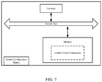
- FIG. 7 is a structural diagram of the gimbal provided by the present disclosure.
- the gimbal includes a memory, a processor, and a follow-configuration button.
- the memory is used to store control instructions of the gimbal.
- the processor calls the control instructions and performs operations including detecting whether the follow-configuration button is triggered and adjusting the follow parameters of the gimbal for following the target object according to the trigger when the trigger is detected.
- the follow-configuration button is a physical button, or the follow-configuration button can be a virtual button displayed on a screen provided at the gimbal.
- the gimbal is a handheld gimbal and includes a handle.
- the number of the physical buttons is at least one and the physical buttons are disposed at the handle.
- the processor calls the control instruction of the gimbal to perform the adjustment of the follow parameters of the gimbal for following the target object according to the trigger, which includes determining that a corresponding follow coefficient after the trigger is received by the follow-configuration button, and adjusting the follow parameters of the gimbal for following the target object according to the follow coefficient.
- the processor calls the control instruction of the gimbal to perform the determination of the follow coefficient corresponding to the follow-configuration button after receiving the trigger, which includes identifying a first state corresponding to the follow-configuration button before receiving the trigger, determining that the follow-configuration button is sequentially switched from the first state to a second state according to a specified state cycle order after receiving the trigger, and determining that the follow coefficient corresponding to the second state is the follow coefficient corresponding to the follow-configuration button after receiving the trigger.
- the corresponding follow coefficients are different, or if the states corresponding to the follow-configuration buttons are different, but the corresponding follow coefficients are the same.
- the follow coefficient includes a follow speed coefficient.
- the follow speed coefficients include follow speed coefficients corresponding to different rotation axes, and the follow speed coefficients corresponding to different rotation axes are the same or different.
- the gimbal further includes at least one rotation axis for adjusting the attitude of the gimbal.
- the processor calls the control instruction of the gimbal to perform the adjustment of the follow parameters of the gimbal for following the target object according to the follow coefficients, which includes, for each rotation axis, obtaining a first difference value by calculating a difference between the handle attitude information and the gimbal target attitude information along the rotation axis, calculating the follow speed of the gimbal for following the target object along the rotation axis according to the first difference value and the follow speed coefficient corresponding to the rotation axis, and controlling the gimbal to follow the target object along the rotation axis according to the follow speed.
- the follow coefficient further includes a follow dead band.
- the follow dead band includes follow dead bands corresponding to different rotation axes, and the follow dead bands corresponding to different rotation axes are the same or different.
- the processor calls the control instruction of the gimbal to perform the calculation of the follow speed of the gimbal for following the target object along the rotation axis according to the calculated first difference value and the follow speed coefficient corresponding to the rotation axis, which includes comparing the absolute value of the first difference value with the follow dead band corresponding to the rotation axis. If the absolute value of the first difference value is greater than the follow dead band corresponding to the rotation axis, a second difference value is obtained by calculating the difference between the absolute value of the first difference value and the follow dead band corresponding to the rotation axis, and a gimbal follow speed for following the target object along the rotation axis is calculated using the second difference value and the follow speed coefficient corresponding to the rotation axis.
- the processor calls the control instruction of the gimbal to perform the calculation of the follow speed of the gimbal for following the target object along the rotation axis according to the calculated first difference value and the follow speed coefficient corresponding to the rotation axis, which includes comparing the absolute value of the first difference value with the follow dead band corresponding to the rotation axis. If the absolute value of the first difference value is not greater than the follow dead band corresponding to the rotation axis, the gimbal follow speed for following the target object along the rotation axis is determined as zero.
- the processor calls the control instruction to control the gimbal to follow the target object along the rotation axis according to the follow speed, which includes controlling the gimbal to stop following the target object along the rotation axis.
- the handle attitude information along the rotation axis includes a Euler angle of the handle along the rotation axis.
- the processor calls the control instruction of the gimbal to determine the Euler angle of the handle along the rotation axis, which includes obtaining the attitude quaternion of the handle along the rotation axis by rotating the attitude quaternion of the inertial measurement element
- IMU itself around the rotation axis of the gimbal and converting the attitude quaternion of the handle along the rotation axis into the Euler angle of the handle along the rotation axis.
- the processor calls the control instruction of the gimbal to perform the determination of the gimbal target attitude information along the rotation axis, which includes determining the gimbal target attitude information along the rotation axis according to the follow speed of the gimbal for following the target object along the rotation axis when receiving the trigger.
- the processor calls the control instruction of the gimbal to perform the determination of the gimbal target attitude information along the rotation axis according to the follow speed of the gimbal for following the target object along the rotation axis after receiving the trigger, which includes obtaining the gimbal target attitude information along the rotation axis by integrating the follow speed of the gimbal for following the target object along the rotation axis after receiving the trigger.
- the follow speed coefficient can be pre-configured through an application program (APP).
- APP application program
- the pre-configured follow speed coefficient can be adaptively adjusted according to requirements.
- the follow dead band can be pre-configured through an application program (APP).
- APP application program
- the pre-configured follow dead band can be adaptively adjusted according to requirements.
- Embodiment 5 is described above.
- a machine-readable storage medium is provided in embodiment 6.
- the machine-readable storage medium includes a U disk, a mobile hard disk, a read-only memory (ROM), a random access memory (RAM), a magnetic disk, or an optical disk, and etc., which can store program codes.
- a plurality of computer instructions are stored on the machine-readable storage medium.
- the processing of the foregoing embodiments 1 to 4 is performed, which specifically includes detecting whether the follow-configuration button provided at the gimbal is triggered and adjusting the follow parameters of the gimbal for following the target object according to the trigger when the trigger is detected.
- the follow-configuration button is a physical button, or the follow-configuration button can be a virtual button.
- the number of the follow-configuration button is at least one.
- the computer instruction is executed to adjust the follow parameters of the gimbal for following the target object according to the trigger, which includes determining that a corresponding follow coefficient after the trigger is received by the follow-configuration button, and adjusting the follow parameters of the gimbal for following the target object according to the follow coefficient.
- the computer instruction is executed to determine the follow coefficient corresponding to the follow-configuration button after receiving the trigger, which includes identifying a first state corresponding to the follow-configuration button before receiving the trigger, determining that the follow-configuration button is sequentially switched from the first state to a second state according to a specified state cycle order after receiving the trigger, and determining that the follow coefficient corresponding to the second state is the follow coefficient corresponding to the follow-configuration button after receiving the trigger.
- the corresponding follow coefficients are different, or if the states corresponding to the follow-configuration buttons are different, but the corresponding follow coefficients are the same.
- the follow coefficient includes a follow speed coefficient.
- the follow speed coefficients include follow speed coefficients corresponding to different rotation axes, and the follow speed coefficients corresponding to different rotation axes are the same or different.
- the computer instruction is executed to adjust the follow parameters of the gimbal for following the target object according to the follow coefficients, which includes for each rotation axis, obtaining a first difference value by calculating the difference between the handle attitude information and the gimbal target attitude information along the rotation axis, calculating the follow speed of the gimbal for following the target object along the rotation axis according to the first difference value and the follow speed coefficient corresponding to the rotation axis, and controlling the gimbal to follow the target object along the rotation axis according to the follow speed.
- the follow coefficients which includes for each rotation axis, obtaining a first difference value by calculating the difference between the handle attitude information and the gimbal target attitude information along the rotation axis, calculating the follow speed of the gimbal for following the target object along the rotation axis according to the first difference value and the follow speed coefficient corresponding to the rotation axis, and controlling the gimbal to follow the target object along the rotation axis according to the follow speed.
- the follow coefficient further includes a follow dead band.
- the follow dead band includes follow dead bands corresponding to different rotation axes, and the follow dead bands corresponding to different rotation axes are the same or different.
- the computer instruction is executed to perform the calculation of the follow speed of the gimbal for following the target object along the rotation axis according to the first difference value and the follow speed coefficient corresponding to the rotation axis, which includes comparing the absolute value of the first difference value with the follow dead band corresponding to the rotation axis. If the absolute value of the first difference value is greater than the follow dead band corresponding to the rotation axis, a second difference value is obtained by calculating the difference between the absolute value of the first difference value and the follow dead band corresponding to the rotation axis, and a gimbal follow speed for following the target object along the rotation axis is calculated using the second difference value and the follow speed coefficient corresponding to the rotation axis.
- the computer instruction is executed to perform the calculation of the follow speed of the gimbal for following the target object along the rotation axis according to the calculated first difference value and the follow speed coefficient corresponding to the rotation axis, which includes comparing the absolute value of the first difference value with the follow dead band corresponding to the rotation axis. If the absolute value of the first difference value is not greater than the follow dead band corresponding to the rotation axis, the gimbal follow speed for following the target object along the rotation axis is determined as zero.
- the computer instruction is executed to control the gimbal to follow the target object along the rotation axis according to the follow speed, which includes controlling the gimbal to stop following the target object along the rotation axis.
- the handle attitude information along the rotation axis includes a Euler angle of the handle along the rotation axis.
- the Euler angle of the handle along the rotation axis includes the Euler angle of the handle along the rotation axis obtained by converting the attitude quaternion of the handle along the rotation axis, which is obtained by rotating the attitude quaternion of the inertial measurement element (IMU) itself around the rotation axis of the gimbal.
- IMU inertial measurement element
- the computer instruction is executed to perform the determination of the gimbal target attitude information along the rotation axis, which includes determining the gimbal target attitude information along the rotation axis according to the follow speed of the gimbal for following the target object along the rotation axis when receiving the trigger.
- the computer instruction is executed to perform the determination of the gimbal target attitude information along the rotation axis according to the follow speed of the gimbal for following the target object along the rotation axis after receiving the trigger, which includes obtaining the gimbal target attitude information along the rotation axis by integrating the follow speed of the gimbal for following the target object along the rotation axis after receiving the trigger.
- the follow speed coefficient can be pre-configured and the pre-configured follow speed coefficient can be adaptively adjusted according to requirements.
- the follow dead band can be pre-configured and the pre-configured follow dead band can be adaptively adjusted according to requirements.
- Embodiment 6 is described above.
- the relevant part may refer to the description of the method embodiment.
- the device embodiments described above are only schematic.
- the units described as separate components may or may not be physically separated, and the components shown as units may or may not be physical units, that is, they may be located at one place, or may be distributed across multiple network units. Some or all of the modules may be selected according to actual needs to achieve the objective of the embodiment. Those of ordinary skill in the art can understand and implement the embodiments without creative efforts.
- relational terms such as first and second are only used to distinguish one entity or operation from another entity or operation, and do not necessarily require or imply that there is any such actual relationship or order between these entities or operations.
- the term “comprising,” “including” or any other variation thereof is non-exclusive inclusion, such that a process, method, article, or device that include a series of elements include not only those elements but also other elements that are not explicitly listed, or elements that are inherent to such a process, method, article, or device. Without more restrictions, the elements defined by the sentence “including a " do not exclude the existence of other identical elements in the process, method, article, or equipment that includes the elements.
Landscapes
- Engineering & Computer Science (AREA)
- General Engineering & Computer Science (AREA)
- Mechanical Engineering (AREA)
- Physics & Mathematics (AREA)
- General Physics & Mathematics (AREA)
- Automation & Control Theory (AREA)
- Studio Devices (AREA)
- Accessories Of Cameras (AREA)
- User Interface Of Digital Computer (AREA)
- Control Of Position Or Direction (AREA)
- Telephone Function (AREA)
Applications Claiming Priority (1)
| Application Number | Priority Date | Filing Date | Title |
|---|---|---|---|
| PCT/CN2018/071534 WO2019134117A1 (fr) | 2018-01-05 | 2018-01-05 | Procédé de commande de panoramique horizontal-vertical, panoramique horizontal-vertical et support d'informations lisible par machine |
Publications (2)
| Publication Number | Publication Date |
|---|---|
| EP3737082A1 true EP3737082A1 (fr) | 2020-11-11 |
| EP3737082A4 EP3737082A4 (fr) | 2020-12-23 |
Family
ID=67144105
Family Applications (1)
| Application Number | Title | Priority Date | Filing Date |
|---|---|---|---|
| EP18898954.5A Withdrawn EP3737082A4 (fr) | 2018-01-05 | 2018-01-05 | Procédé de commande de panoramique horizontal-vertical, panoramique horizontal-vertical et support d'informations lisible par machine |
Country Status (5)
| Country | Link |
|---|---|
| US (2) | US11280447B2 (fr) |
| EP (1) | EP3737082A4 (fr) |
| JP (1) | JP7024155B2 (fr) |
| CN (2) | CN110313171B (fr) |
| WO (1) | WO2019134117A1 (fr) |
Families Citing this family (6)
| Publication number | Priority date | Publication date | Assignee | Title |
|---|---|---|---|---|
| CN109885105B (zh) * | 2016-12-30 | 2022-04-19 | 深圳市大疆灵眸科技有限公司 | 云台控制方法、装置及云台 |
| CN109213207B (zh) * | 2017-06-29 | 2022-03-29 | 北京远度互联科技有限公司 | 云台镜头调整方法、装置及手持云台 |
| EP3737082A4 (fr) * | 2018-01-05 | 2020-12-23 | SZ DJI Technology Co., Ltd. | Procédé de commande de panoramique horizontal-vertical, panoramique horizontal-vertical et support d'informations lisible par machine |
| WO2021026784A1 (fr) * | 2019-08-13 | 2021-02-18 | 深圳市大疆创新科技有限公司 | Procédé de photographie de suivi, procédé de commande de cardan, appareil photographique, cardan portatif et système photographique |
| CN113464800B (zh) * | 2021-07-12 | 2022-07-15 | 珠海格力电器股份有限公司 | 摄像机 |
| CN120602785B (zh) * | 2025-08-07 | 2025-10-28 | 深圳壹秘科技有限公司 | 目标跟踪拍摄方法、设备以及存储介质 |
Family Cites Families (23)
| Publication number | Priority date | Publication date | Assignee | Title |
|---|---|---|---|---|
| JPH05150030A (ja) * | 1991-11-29 | 1993-06-18 | Nec Corp | 目標追尾装置 |
| JP3959363B2 (ja) * | 2003-03-28 | 2007-08-15 | 日本航空電子工業株式会社 | 画像追尾制御方法 |
| CN102196240B (zh) * | 2010-03-18 | 2014-08-20 | 鸿富锦精密工业(深圳)有限公司 | 摄像装置及利用其动态侦测监控对象的方法 |
| JP5540850B2 (ja) * | 2010-04-09 | 2014-07-02 | トヨタ自動車株式会社 | 姿勢推定装置、方法及びプログラム |
| TWI432347B (zh) * | 2011-03-11 | 2014-04-01 | Wistron Corp | 可自動調整方位的支架裝置,及該支架裝置與電子裝置的組合 |
| CN102355574B (zh) * | 2011-10-17 | 2013-12-25 | 上海大学 | 机载云台运动目标自主跟踪系统的图像稳定方法 |
| CN102662404A (zh) * | 2012-03-31 | 2012-09-12 | 天津九安医疗电子股份有限公司 | 一种云台控制装置及云台的控制方法 |
| WO2014140356A1 (fr) * | 2013-03-15 | 2014-09-18 | Freefly Systems Inc. | Procédé pour permettre un ajustement manuel d'une direction d'orientation d'une caméra activement stabilisée |
| US9319589B2 (en) * | 2013-05-31 | 2016-04-19 | Sony Corporation | Device and method for capturing images and selecting a desired image by tilting the device |
| CN103984193B (zh) * | 2014-03-14 | 2020-10-16 | 广州虹天航空科技有限公司 | 拍摄设备稳定器及其控制方法 |
| CN105223967B (zh) * | 2014-06-30 | 2017-11-28 | 深圳市大疆灵眸科技有限公司 | 一种摄像控制方法、装置及云台设备 |
| WO2016000193A1 (fr) * | 2014-06-30 | 2016-01-07 | 深圳市大疆创新科技有限公司 | Procédé de réglage d'un paramètre de support, dispositif et dispositif de support |
| CN105518757B (zh) * | 2015-01-06 | 2018-06-12 | 深圳市大疆灵眸科技有限公司 | 云台遥控器及采用该云台遥控器的手持云台 |
| CN106662793B (zh) * | 2015-05-27 | 2019-06-11 | 高途乐公司 | 使用稳定用常平架的常平架系统 |
| PL3236312T3 (pl) * | 2016-04-20 | 2019-10-31 | Guilin Feiyu Tech Corporation Ltd | Trójosiowy stabilizator do telefonu komórkowego |
| WO2017206072A1 (fr) * | 2016-05-31 | 2017-12-07 | 深圳市大疆灵眸科技有限公司 | Procédé et appareil de commande de panoramique horizontal/vertical, et panoramique horizontal/vertical |
| CN106249888A (zh) * | 2016-07-28 | 2016-12-21 | 纳恩博(北京)科技有限公司 | 一种云台控制方法和装置 |
| CN106249761A (zh) * | 2016-08-11 | 2016-12-21 | 零度智控(北京)智能科技有限公司 | 地面云台控制方法、装置及地面云台 |
| US11295458B2 (en) * | 2016-12-01 | 2022-04-05 | Skydio, Inc. | Object tracking by an unmanned aerial vehicle using visual sensors |
| WO2018098784A1 (fr) * | 2016-12-01 | 2018-06-07 | 深圳市大疆创新科技有限公司 | Procédé, dispositif, équipement et système de commande de véhicule aérien sans pilote |
| CN106774435A (zh) * | 2017-01-20 | 2017-05-31 | 亿航智能设备(广州)有限公司 | 一种无人机的高精度跟随方法及其系统 |
| EP3737082A4 (fr) * | 2018-01-05 | 2020-12-23 | SZ DJI Technology Co., Ltd. | Procédé de commande de panoramique horizontal-vertical, panoramique horizontal-vertical et support d'informations lisible par machine |
| CN110446885B (zh) * | 2018-01-06 | 2021-05-11 | 深圳市大疆创新科技有限公司 | 非正交云台的控制方法及其云台和存储装置 |
-
2018
- 2018-01-05 EP EP18898954.5A patent/EP3737082A4/fr not_active Withdrawn
- 2018-01-05 JP JP2020526971A patent/JP7024155B2/ja not_active Expired - Fee Related
- 2018-01-05 WO PCT/CN2018/071534 patent/WO2019134117A1/fr not_active Ceased
- 2018-01-05 CN CN201880012001.4A patent/CN110313171B/zh active Active
- 2018-01-05 CN CN202111087801.2A patent/CN113848994B/zh active Active
-
2020
- 2020-05-21 US US16/880,385 patent/US11280447B2/en active Active
-
2022
- 2022-03-21 US US17/699,780 patent/US11739881B2/en active Active
Also Published As
| Publication number | Publication date |
|---|---|
| CN113848994A (zh) | 2021-12-28 |
| JP2021504735A (ja) | 2021-02-15 |
| US20200278072A1 (en) | 2020-09-03 |
| CN110313171B (zh) | 2021-10-15 |
| US20220205583A1 (en) | 2022-06-30 |
| EP3737082A4 (fr) | 2020-12-23 |
| US11280447B2 (en) | 2022-03-22 |
| JP7024155B2 (ja) | 2022-02-24 |
| CN113848994B (zh) | 2025-04-25 |
| CN110313171A (zh) | 2019-10-08 |
| US11739881B2 (en) | 2023-08-29 |
| WO2019134117A1 (fr) | 2019-07-11 |
Similar Documents
| Publication | Publication Date | Title |
|---|---|---|
| US11739881B2 (en) | Gimbal control method, gimbal and machine-readable storage medium | |
| US20210157217A1 (en) | Gimbal control method, gimbal control apparatus, and gimbal | |
| US11184548B2 (en) | Imaging device, and method and apparatus for controlling the imaging device | |
| CN108521814B (zh) | 云台的控制方法、控制器和云台 | |
| CN104902170B (zh) | 一种拍照方法及终端 | |
| CN109032188A (zh) | 飞行装置和系统 | |
| CN108780324B (zh) | 无人机、无人机控制方法和装置 | |
| US11381751B2 (en) | Handheld gimbal control method, handheld gimbal, and handheld device | |
| US20210018138A1 (en) | Gimbal mode switching method, device, mobile platform and storage medium | |
| EP3751837A1 (fr) | Procédé et appareil de commande de cardan portatif, et cardan portatif | |
| CN112544065A (zh) | 云台的控制方法和云台 | |
| CN111953964B (zh) | 一种模糊度检测方法及电子设备、存储介质 | |
| CN114125268A (zh) | 对焦方法及装置 | |
| WO2018191969A1 (fr) | Procédé et dispositif de commande de support de caméra | |
| CN112728339A (zh) | 一种云台的控制方法以及云台 | |
| CN117781107A (zh) | 云台稳定器、云台拍摄系统、追踪方法、装置及设备 | |
| CN113287296A (zh) | 控制方法、手持云台、系统及计算机可读存储介质 | |
| CN115379118B (zh) | 摄像头切换方法、装置、电子设备和可读存储介质 | |
| CN113873157B (zh) | 拍摄方法、装置、电子设备和可读存储介质 | |
| WO2023179440A1 (fr) | Procédé et appareil de commande d'appareil de prise de vue, appareil de prise de vue et dispositif électronique | |
| CN117130528A (zh) | 画面显示方法、装置、电子设备及存储介质 | |
| JP2019129463A (ja) | 撮像装置 | |
| CN113261273A (zh) | 参数自适应方法、手持云台、系统及计算机可读存储介质 | |
| CN110345362A (zh) | 跟拍辅助器件、跟拍辅助设备及其定位控制器的定位控制方法 | |
| CN113016174A (zh) | 画面切换方法、装置、终端设备、系统及存储介质 |
Legal Events
| Date | Code | Title | Description |
|---|---|---|---|
| STAA | Information on the status of an ep patent application or granted ep patent |
Free format text: STATUS: THE INTERNATIONAL PUBLICATION HAS BEEN MADE |
|
| PUAI | Public reference made under article 153(3) epc to a published international application that has entered the european phase |
Free format text: ORIGINAL CODE: 0009012 |
|
| STAA | Information on the status of an ep patent application or granted ep patent |
Free format text: STATUS: REQUEST FOR EXAMINATION WAS MADE |
|
| 17P | Request for examination filed |
Effective date: 20200319 |
|
| AK | Designated contracting states |
Kind code of ref document: A1 Designated state(s): AL AT BE BG CH CY CZ DE DK EE ES FI FR GB GR HR HU IE IS IT LI LT LU LV MC MK MT NL NO PL PT RO RS SE SI SK SM TR |
|
| AX | Request for extension of the european patent |
Extension state: BA ME |
|
| A4 | Supplementary search report drawn up and despatched |
Effective date: 20201125 |
|
| RIC1 | Information provided on ipc code assigned before grant |
Ipc: F16M 11/08 20060101ALI20201119BHEP Ipc: F16M 11/10 20060101ALI20201119BHEP Ipc: H04N 5/232 20060101AFI20201119BHEP |
|
| DAV | Request for validation of the european patent (deleted) | ||
| DAX | Request for extension of the european patent (deleted) | ||
| STAA | Information on the status of an ep patent application or granted ep patent |
Free format text: STATUS: EXAMINATION IS IN PROGRESS |
|
| 17Q | First examination report despatched |
Effective date: 20210901 |
|
| GRAP | Despatch of communication of intention to grant a patent |
Free format text: ORIGINAL CODE: EPIDOSNIGR1 |
|
| STAA | Information on the status of an ep patent application or granted ep patent |
Free format text: STATUS: GRANT OF PATENT IS INTENDED |
|
| INTG | Intention to grant announced |
Effective date: 20220810 |
|
| STAA | Information on the status of an ep patent application or granted ep patent |
Free format text: STATUS: THE APPLICATION IS DEEMED TO BE WITHDRAWN |
|
| 18D | Application deemed to be withdrawn |
Effective date: 20221221 |