EP3737136B1 - Parameterkonfigurationsverfahren und zugehörige produkte - Google Patents
Parameterkonfigurationsverfahren und zugehörige produkte Download PDFInfo
- Publication number
- EP3737136B1 EP3737136B1 EP18900058.1A EP18900058A EP3737136B1 EP 3737136 B1 EP3737136 B1 EP 3737136B1 EP 18900058 A EP18900058 A EP 18900058A EP 3737136 B1 EP3737136 B1 EP 3737136B1
- Authority
- EP
- European Patent Office
- Prior art keywords
- terminal
- bwp
- parameter
- network device
- parameters
- Prior art date
- Legal status (The legal status is an assumption and is not a legal conclusion. Google has not performed a legal analysis and makes no representation as to the accuracy of the status listed.)
- Active
Links
Images


Classifications
-
- H—ELECTRICITY
- H04—ELECTRIC COMMUNICATION TECHNIQUE
- H04W—WIRELESS COMMUNICATION NETWORKS
- H04W72/00—Local resource management
- H04W72/04—Wireless resource allocation
- H04W72/044—Wireless resource allocation based on the type of the allocated resource
- H04W72/0453—Resources in frequency domain, e.g. a carrier in FDMA
-
- H—ELECTRICITY
- H04—ELECTRIC COMMUNICATION TECHNIQUE
- H04L—TRANSMISSION OF DIGITAL INFORMATION, e.g. TELEGRAPHIC COMMUNICATION
- H04L5/00—Arrangements affording multiple use of the transmission path
- H04L5/003—Arrangements for allocating sub-channels of the transmission path
- H04L5/0048—Allocation of pilot signals, i.e. of signals known to the receiver
- H04L5/0051—Allocation of pilot signals, i.e. of signals known to the receiver of dedicated pilots, i.e. pilots destined for a single user or terminal
-
- H—ELECTRICITY
- H04—ELECTRIC COMMUNICATION TECHNIQUE
- H04L—TRANSMISSION OF DIGITAL INFORMATION, e.g. TELEGRAPHIC COMMUNICATION
- H04L5/00—Arrangements affording multiple use of the transmission path
- H04L5/0001—Arrangements for dividing the transmission path
- H04L5/0003—Two-dimensional division
- H04L5/0005—Time-frequency
- H04L5/0007—Time-frequency the frequencies being orthogonal, e.g. OFDM(A) or DMT
-
- H—ELECTRICITY
- H04—ELECTRIC COMMUNICATION TECHNIQUE
- H04L—TRANSMISSION OF DIGITAL INFORMATION, e.g. TELEGRAPHIC COMMUNICATION
- H04L5/00—Arrangements affording multiple use of the transmission path
- H04L5/0001—Arrangements for dividing the transmission path
- H04L5/0003—Two-dimensional division
- H04L5/0005—Time-frequency
- H04L5/0007—Time-frequency the frequencies being orthogonal, e.g. OFDM(A) or DMT
- H04L5/001—Time-frequency the frequencies being orthogonal, e.g. OFDM(A) or DMT the frequencies being arranged in component carriers
-
- H—ELECTRICITY
- H04—ELECTRIC COMMUNICATION TECHNIQUE
- H04L—TRANSMISSION OF DIGITAL INFORMATION, e.g. TELEGRAPHIC COMMUNICATION
- H04L5/00—Arrangements affording multiple use of the transmission path
- H04L5/003—Arrangements for allocating sub-channels of the transmission path
- H04L5/0048—Allocation of pilot signals, i.e. of signals known to the receiver
-
- H—ELECTRICITY
- H04—ELECTRIC COMMUNICATION TECHNIQUE
- H04L—TRANSMISSION OF DIGITAL INFORMATION, e.g. TELEGRAPHIC COMMUNICATION
- H04L5/00—Arrangements affording multiple use of the transmission path
- H04L5/003—Arrangements for allocating sub-channels of the transmission path
- H04L5/0048—Allocation of pilot signals, i.e. of signals known to the receiver
- H04L5/005—Allocation of pilot signals, i.e. of signals known to the receiver of common pilots, i.e. pilots destined for multiple users or terminals
-
- H—ELECTRICITY
- H04—ELECTRIC COMMUNICATION TECHNIQUE
- H04L—TRANSMISSION OF DIGITAL INFORMATION, e.g. TELEGRAPHIC COMMUNICATION
- H04L5/00—Arrangements affording multiple use of the transmission path
- H04L5/0091—Signalling for the administration of the divided path, e.g. signalling of configuration information
- H04L5/0094—Indication of how sub-channels of the path are allocated
-
- H—ELECTRICITY
- H04—ELECTRIC COMMUNICATION TECHNIQUE
- H04W—WIRELESS COMMUNICATION NETWORKS
- H04W16/00—Network planning, e.g. coverage or traffic planning tools; Network deployment, e.g. resource partitioning or cells structures
- H04W16/02—Resource partitioning among network components, e.g. reuse partitioning
- H04W16/04—Traffic adaptive resource partitioning
-
- H—ELECTRICITY
- H04—ELECTRIC COMMUNICATION TECHNIQUE
- H04W—WIRELESS COMMUNICATION NETWORKS
- H04W24/00—Supervisory, monitoring or testing arrangements
- H04W24/02—Arrangements for optimising operational condition
-
- H—ELECTRICITY
- H04—ELECTRIC COMMUNICATION TECHNIQUE
- H04W—WIRELESS COMMUNICATION NETWORKS
- H04W28/00—Network traffic management; Network resource management
- H04W28/16—Central resource management; Negotiation of resources or communication parameters, e.g. negotiating bandwidth or QoS [Quality of Service]
- H04W28/18—Negotiating wireless communication parameters
- H04W28/20—Negotiating bandwidth
-
- H—ELECTRICITY
- H04—ELECTRIC COMMUNICATION TECHNIQUE
- H04W—WIRELESS COMMUNICATION NETWORKS
- H04W52/00—Power management, e.g. Transmission Power Control [TPC] or power classes
- H04W52/04—Transmission power control [TPC]
- H04W52/30—Transmission power control [TPC] using constraints in the total amount of available transmission power
- H04W52/32—TPC of broadcast or control channels
- H04W52/325—Power control of control or pilot channels
-
- H—ELECTRICITY
- H04—ELECTRIC COMMUNICATION TECHNIQUE
- H04W—WIRELESS COMMUNICATION NETWORKS
- H04W52/00—Power management, e.g. Transmission Power Control [TPC] or power classes
- H04W52/04—Transmission power control [TPC]
- H04W52/30—Transmission power control [TPC] using constraints in the total amount of available transmission power
- H04W52/36—Transmission power control [TPC] using constraints in the total amount of available transmission power with a discrete range or set of values, e.g. step size, ramping or offsets
-
- H—ELECTRICITY
- H04—ELECTRIC COMMUNICATION TECHNIQUE
- H04W—WIRELESS COMMUNICATION NETWORKS
- H04W72/00—Local resource management
- H04W72/04—Wireless resource allocation
- H04W72/044—Wireless resource allocation based on the type of the allocated resource
- H04W72/0446—Resources in time domain, e.g. slots or frames
-
- H—ELECTRICITY
- H04—ELECTRIC COMMUNICATION TECHNIQUE
- H04W—WIRELESS COMMUNICATION NETWORKS
- H04W72/00—Local resource management
- H04W72/20—Control channels or signalling for resource management
- H04W72/21—Control channels or signalling for resource management in the uplink direction of a wireless link, i.e. towards the network
-
- H—ELECTRICITY
- H04—ELECTRIC COMMUNICATION TECHNIQUE
- H04W—WIRELESS COMMUNICATION NETWORKS
- H04W72/00—Local resource management
- H04W72/20—Control channels or signalling for resource management
- H04W72/23—Control channels or signalling for resource management in the downlink direction of a wireless link, i.e. towards a terminal
-
- H—ELECTRICITY
- H04—ELECTRIC COMMUNICATION TECHNIQUE
- H04W—WIRELESS COMMUNICATION NETWORKS
- H04W48/00—Access restriction; Network selection; Access point selection
- H04W48/08—Access restriction or access information delivery, e.g. discovery data delivery
- H04W48/12—Access restriction or access information delivery, e.g. discovery data delivery using downlink control channel
Definitions
- This application relates to the field of communications technologies, and in particular, to a parameter configuration method and a related product.
- a carrier may include a plurality of bandwidth parts (BWP).
- BWP bandwidth parts
- For a terminal only one uplink BWP can be activated at one moment and used for uplink transmission.
- DCI downlink control information
- a BWP of the terminal that is currently activated is indicated by using downlink control information (DCI) or the like.
- DCI downlink control information
- the BWP used by the terminal for transmission can be dynamically switched among a plurality of BWPs in a carrier. How to efficiently configure a terminal to perform transmission on different BWPs is a technical problem that needs to be resolved.
- Embodiments of this application provide a parameter configuration method and a related product, to help improve flexibility of configuring a BWP by a PT-RS, as defined in the independent claims.
- a network device indicates a parameter of a phase tracking reference signal PT-RS to a terminal.
- the parameter of the PT-RS is configured for a bandwidth part BWP of the terminal.
- the parameter is used for indicating resource information that needs to be used by the terminal when the terminal sends or receives the PT-RS on the BWP.
- the terminal Because the parameter can determine the resource information that needs to be used by the terminal when the terminal sends or receives the PT-RS on the BWP, the terminal only needs to obtain the parameter of the PT-RS corresponding to a to-be-used BWP when switching the BWP, so that the resource information that needs to be used for sending or receiving the PT-RS is flexibly determined, thereby helping improve flexibility of configuring a BWP by a PT-RS.
- FIG. 1 shows a wireless communications system related to this application.
- the wireless communications system may operate on a high frequency band, and may be a future evolved 5th generation mobile communications (the 5th Generation, 5G) system, a new radio (NR) system, a machine to machine communications (M2M) system, or the like.
- the wireless communications system 100 may include: one or more network devices 101, one or more terminals 103, and a core network device 105.
- the network device 101 may be a base station.
- the base station may be configured to communicate with one or more terminals, or may be configured to communicate with one or more base stations (for example, communicate with a macro base station and a micro base station such as an access point) that have some functions of a terminal.
- the base station may be a base transceiver station (BTS) in a time division synchronous code division multiple access (TD-SCDMA) system, or may be an evolved NodeB (eNB) in an LTE system, and a base station in the 5G system and the new radio (NR) system.
- the base station may be an access point (AP), a transit node (Trans TRP), a central unit (CU), or another network entity, and may include some or all functions of the foregoing network entities.
- the core network device 105 includes a device on a core network side such as a serving gateway (SGW).
- SGW serving gateway
- the terminal 103 may be distributed in the entire wireless communications system 100, and may be static or moving.
- the terminal 103 may be a mobile device (for example, a smartphone), a mobile station, a mobile unit, an M2M terminal, a radio unit, a remote unit, a user agent, a mobile client, and the like.
- the wireless communications system 100 shown in FIG. 1 merely aims to more clearly describe the technical solutions in this application, but are not intended to limit this application.
- a person of ordinary skill in the art may know that as the network architectures evolve and a new business scenario emerges, the technical solutions provided in this application further apply to a similar technical problem.
- one terminal can configure a plurality of downlink DL BWPs or uplink UP BWPs, and relatively dynamically perform transmission on different BWPs by using manners such as DCI/media access control layer control element MAC CE, and the like.
- PT-RS phase tracking reference signal
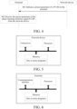
- FIG. 2 shows a parameter configuration method according to an embodiment of this application.
- the method is applied to the foregoing exemplary communications system, and the method includes:
- a network device indicates a parameter of a phase tracking reference signal PT-RS to a terminal.
- the parameter of the PT-RS is configured for a bandwidth part BWP of the terminal.
- the parameter is used for indicating resource information that needs to be used by the terminal when the terminal sends or receives the PT-RS on the BWP.
- the PT-RS is used for suppressing an impact of phase noise on system performance.
- the network device indicates the parameter of the phase tracking reference signal PT-RS to the terminal by using radio resource control RRC signaling.
- a network device indicates a parameter of a phase tracking reference signal PT-RS to a terminal.
- the parameter of the PT-RS is configured for a bandwidth part BWP of the terminal.
- the parameter is used for indicating resource information that needs to be used by the terminal when the terminal sends or receives the PT-RS on the BWP.
- the terminal Because the parameter can determine the resource information that needs to be used by the terminal when the terminal sends or receives the PT-RS on the BWP, the terminal only needs to obtain the parameter of the PT-RS corresponding to a to-be-used BWP when switching the BWP, so that the resource information that needs to be used for sending or receiving the PT-RS is flexibly determined, thereby helping improve flexibility of configuring a BWP by a PT-RS. For example, in different bandwidth parts BWP, one terminal may perform multi-user multiple-input multiple-output technology MU-MIMO paring (user paring for short) with different terminals. In this way, for different BWPs, the network device configures parameters of different PT-RSs, thereby flexibly performing the multi-user paring with other terminals on different BWPs.
- MU-MIMO paring user paring for short
- each parameter corresponds to one or more BWPs.
- the PT-RS includes a downlink DL PT-RS or an uplink UL PT-RS.
- the parameter includes at least one resource block RB offset parameter, and the RB offset parameter is used for indicating a physical resource block PRB location used by the terminal when the terminal sends or receives the PT-RS on the BWP.
- the network device configures M bandwidth parts BWP (which may be uplink BWPs, or downlink BWPs) for the terminal; and for the PT-RS, the network device configures N (N ⁇ M) resource block RB offset parameters for the terminal.
- BWP bandwidth parts
- N resource block RB offset parameters
- One resource block RB offset parameter corresponds to one or more BWPs.
- RB locations used for performing PT-RS transmission are more flexibly configured on different BWPs by independently configuring resource block RB offset parameters for different BWPs.
- the parameter includes at least one resource element RE offset parameter, and the at least one RE offset parameter is used for indicating an RE location used by the terminal when the terminal sends or receives the PT-RS on the BWP.
- the network device configures M bandwidth parts BWP (which may be uplink BWPs, or downlink BWPs) for the terminal; and for the PT-RS, the network device configures N (N ⁇ M) RE offset parameters for the terminal.
- BWP bandwidth parts
- N N ⁇ M RE offset parameters
- One RE offset parameter corresponds to one BWP.
- the network device instructs, by using signaling, the terminal to activate a BWP, the terminal selects, according to the correspondence, an RE offset parameter corresponding to the activated BWP, to determine an RE location used by the PT-RS.
- RE locations used for performing PT-RS transmission are more flexibly configured on different BWPs by independently configuring RE offset parameters for different BWPs.
- the parameter includes at least one power offset parameter, and the at least one power offset parameter is used for indicating a power of the terminal when the terminal sends or receives the PT-RS on the BWP.
- the network device configures M bandwidth parts BWP (which may be uplink BWPs, or downlink BWPs) for the terminal; and for the PT-RS, the network device configures N (N ⁇ M) power offset parameters for the terminal.
- BWP bandwidth parts
- N N ⁇ M power offset parameters
- One power offset parameter corresponds to one BWP.
- the network device instructs, by using signaling, the terminal to activate a BWP
- the terminal selects, according to the correspondence, a power offset parameter corresponding to the activated BWP, to determine a power used by the PT-RS.
- a power used for performing PT-RS transmission is more flexibly configured on different BWPs by independently configuring power offset parameters for different BWPs.
- the network device configures the terminal to use a discrete fourier transform spread orthogonal frequency division multiplexing technology DFT-S-OFDM standard, and the PT-RS is an uplink UL PT-RS.
- DFT-S-OFDM discrete fourier transform spread orthogonal frequency division multiplexing technology
- the DFT-S-OFDM corresponds to a transform precoding technology.
- resource information used for performing UL PT-RS transmission is more flexibly configured on different BWPs by independently configuring parameters of the UL PT-RSs for different BWPs.
- the parameter includes a time density, and the time density is used for determining a time domain location of the terminal when the terminal sends or receives the PT-RS on the BWP.
- the network device configures M bandwidth parts BWP (which may be uplink BWPs, or downlink BWPs) for the terminal; and for the PT-RS, the network device configures N (N ⁇ M) time domain densities for the terminal.
- BWP bandwidth parts
- N N ⁇ M time domain densities for the terminal.
- One time density corresponds to one or more BWPs.
- the network device instructs, by using signaling, the terminal to activate a BWP, the terminal selects, according to the correspondence, a time density corresponding to the activated BWP, to determine a time domain location used by the PT-RS.
- time domain locations used for performing PT-RS transmission is more flexibly configured on different BWPs by independently configuring time domain densities for different BWPs.
- FIG. 3 shows another parameter configuration method according to an embodiment of this application.
- the method is applied to the foregoing exemplary communications system, and the method includes:
- a terminal receives a parameter of a phase tracking reference signal PT-RS from a network device.
- the parameter of the PT-RS is configured for a bandwidth part BWP of the terminal.
- the parameter is used for indicating resource information that needs to be used by the terminal when the terminal sends or receives the PT-RS on the BWP.
- the terminal because the parameter of the PT-RS can indicate the resource information that needs to be used by the terminal when the terminal sends or receives the PT-RS on the BWP, the terminal only needs to obtain the parameter when the BWP of the terminal is switched, so that the resource information used for sending or receiving the PT-RS on a to-be-used BWP is accurately determined, thereby helping improve flexibility of configuring a BWP by a PT-RS.
- one terminal may perform multi-user multiple-input multiple-output technology MU-MIMO paring with different terminals. In this way, for different BWPs, the network device configures parameters of different PT-RSs, thereby flexibly performing the multi-user paring with other terminals on different BWPs.
- each parameter corresponds to one or more BWPs.
- the PT-RS includes a downlink DL PT-RS or an uplink UL PT-RS.
- the parameter includes at least one resource block RB offset parameter
- the method further includes: determining, by the terminal according to the RB offset parameter, a physical resource block PRB location used by the terminal when the terminal sends or receives the PT-RS on the BWP.
- the network device configures M bandwidth parts BWP (which may be uplink BWPs, or downlink BWPs) for the terminal; and for the PT-RS, the network device configures N (N ⁇ M) resource block RB offset parameters for the terminal.
- BWP bandwidth parts
- N resource block RB offset parameters
- One resource block RB offset parameter corresponds to one or more BWPs.
- RB locations used for performing PT-RS transmission are more flexibly configured on different BWPs by independently configuring resource block RB offset parameters for different BWPs.
- the parameter includes at least one resource element RE offset parameter
- the method further includes: determining, by the terminal according to the at least one RE offset parameter, an RE location used by the terminal when the terminal sends or receives the PT-RS on the BWP.
- the network device configures M bandwidth parts BWP (which may be uplink BWPs, or downlink BWPs) for the terminal; and for the PT-RS, the network device configures N (N ⁇ M) RE offset parameters for the terminal.
- BWP bandwidth parts
- N N ⁇ M RE offset parameters
- One RE offset parameter corresponds to one BWP.
- the network device instructs, by using signaling, the terminal to activate a BWP, the terminal selects, according to the correspondence, an RE offset parameter corresponding to the activated BWP, to determine an RE location used by the PT-RS.
- RE locations used for performing PT-RS transmission are more flexibly configured on different BWPs by independently configuring RE offset parameters for different BWPs.
- the parameter includes at least one power offset parameter
- the method further includes: determining, by the terminal according to the at least one power offset parameter, a power of the terminal when the terminal sends or receives the PT-RS on the BWP.
- the network device configures M bandwidth parts BWP (which may be uplink BWPs, or downlink BWPs) for the terminal; and for the PT-RS, the network device configures N (N ⁇ M) power offset parameters for the terminal.
- BWP bandwidth parts
- N N ⁇ M power offset parameters
- One power offset parameter corresponds to one BWP.
- the network device instructs, by using signaling, the terminal to activate a BWP
- the terminal selects, according to the correspondence, a power offset parameter corresponding to the activated BWP, to determine a power used by the PT-RS.
- a power used for performing PT-RS transmission is more flexibly configured on different BWPs by independently configuring power offset parameters for different BWPs.
- the terminal uses a discrete fourier transform spread orthogonal frequency division multiplexing technology DFT-S-OFDM standard, and the PT-RS is an uplink UL PT-RS.
- DFT-S-OFDM discrete fourier transform spread orthogonal frequency division multiplexing technology
- the DFT-S-OFDM corresponds to a transform precoding technology.
- resource information used for performing UL PT-RS transmission is more flexibly configured on different BWPs by independently configuring parameters of the UL PT-RSs for different BWPs.
- the parameter includes a time density
- the method further includes: determining, by the terminal according to the time density, a time domain location of the terminal when the terminal sends or receives the PT-RS on the BWP.
- the network device configures M bandwidth parts BWP (which may be uplink BWPs, or downlink BWPs) for the terminal; and for the PT-RS, the network device configures N (N ⁇ M) time domain densities for the terminal.
- BWP bandwidth parts
- N N ⁇ M time domain densities for the terminal.
- One time density corresponds to one or more BWPs.
- the network device instructs, by using signaling, the terminal to activate a BWP, the terminal selects, according to the correspondence, a time density corresponding to the activated BWP, to determine a time domain location used by the PT-RS.
- time domain locations used for performing PT-RS transmission is more flexibly configured on different BWPs by independently configuring time domain densities for different BWPs.
- FIG. 4 shows a parameter configuration method according to an embodiment of this application.
- the method is applied to the foregoing exemplary communications system, and the method includes:
- a network device indicates a parameter of a phase tracking reference signal PT-RS to a terminal.
- the parameter of the PT-RS is configured for a bandwidth part BWP of the terminal.
- the parameter is used for indicating resource information that needs to be used by the terminal when the terminal sends or receives the PT-RS on the BWP.
- the terminal receives the parameter of the phase tracking reference signal PT-RS from the network device.
- the parameter of the PT-RS is configured for the bandwidth part of the terminal.
- the parameter is used for indicating the resource information that needs to be used by the terminal when the terminal sends or receives the PT-RS on the BWP.
- a network device indicates a parameter of a phase tracking reference signal PT-RS to a terminal.
- the parameter of the PT-RS is configured for a bandwidth part BWP of the terminal.
- the parameter is used for indicating resource information that needs to be used by the terminal when the terminal sends or receives the PT-RS on the BWP.
- the terminal Because the parameter can determine the resource information that needs to be used by the terminal when the terminal sends or receives the PT-RS on the BWP, the terminal only needs to obtain the parameter of the PT-RS corresponding to a to-be-used BWP when switching the BWP, so that the resource information that needs to be used for sending or receiving the PT-RS is flexibly determined, thereby helping improve flexibility of configuring a BWP by a PT-RS. For example, in different bandwidth parts BWP, one terminal may perform multi-user multiple-input multiple-output technology MU-MIMO paring with different terminals. In this way, for different BWPs, the network device configures parameters of different PT-RSs, thereby flexibly performing the multi-user paring with other terminals on different BWPs.
- MU-MIMO paring multi-user multiple-input multiple-output technology
- FIG. 5 is a schematic structural diagram of a network device according to an embodiment of this application.
- the network device is a first network device.
- the network device includes a processor, a memory, a transceiver, and one or more programs.
- the one or more programs are stored in the memory and are configured to be executed by the processor.
- the program includes an instruction used for performing the following step.
- a parameter of a phase tracking reference signal PT-RS is indicated to a terminal.
- the parameter of the PT-RS is configured for a bandwidth part BWP of the terminal.
- the parameter is used for indicating resource information that needs to be used by the terminal when the terminal sends or receives the PT-RS on the BWP.
- a network device indicates a parameter of a phase tracking reference signal PT-RS to a terminal.
- the parameter of the PT-RS is configured for a bandwidth part BWP of the terminal.
- the parameter is used for indicating resource information that needs to be used by the terminal when the terminal sends or receives the PT-RS on the BWP.
- the terminal Because the parameter can determine the resource information that needs to be used by the terminal when the terminal sends or receives the PT-RS on the BWP, the terminal only needs to obtain the parameter of the PT-RS corresponding to a to-be-used BWP when switching the BWP, so that the resource information that needs to be used for sending or receiving the PT-RS is flexibly determined, thereby helping improve flexibility of configuring a BWP by a PT-RS. For example, in different bandwidth parts BWP, one terminal may perform multi-user multiple-input multiple-output technology MU-MIMO paring with different terminals. In this way, for different BWPs, the network device configures parameters of different PT-RSs, thereby flexibly performing the multi-user paring with other terminals on different BWPs.
- MU-MIMO paring multi-user multiple-input multiple-output technology
- each parameter corresponds to one or more BWPs.
- the PT-RS includes a downlink DL PT-RS or an uplink UL PT-RS.
- the parameter includes at least one resource block RB offset parameter, and the at least one resource block RB offset parameter is used for indicating a physical resource block PRB location used by the terminal when the terminal sends or receives the PT-RS on the BWP.
- the parameter includes at least one resource element RE offset parameter, and the at least one RE offset parameter is used for indicating an RE location used by the terminal when the terminal sends or receives the PT-RS on the BWP.
- the network device configures the terminal to use a discrete fourier transform spread orthogonal frequency division multiplexing technology DFT-S-OFDM standard, and the PT-RS is an uplink UL PT-RS.
- DFT-S-OFDM discrete fourier transform spread orthogonal frequency division multiplexing technology
- the parameter includes a time density, and the time density is used for determining a time domain location of the terminal when the terminal sends or receives the PT-RS on the BWP.
- FIG. 6 is a schematic structural diagram of a terminal according to an embodiment of this application.
- the terminal includes a processor, a memory, a communications interface, and one or more programs.
- the one or more programs are stored in the memory and are configured to be executed by the processor.
- the program includes an instruction used for performing the following step.
- a parameter of a phase tracking reference signal PT-RS from a network device is received.
- the parameter of the PT-RS is configured for a bandwidth part BWP of the terminal.
- the parameter is used for indicating resource information that needs to be used by the terminal when the terminal sends or receives the PT-RS on the BWP.
- the terminal because the parameter of the PT-RS can indicate the resource information that needs to be used by the terminal when the terminal sends or receives the PT-RS on the BWP, the terminal only needs to obtain the parameter when the BWP of the terminal is switched, so that the resource information used for sending or receiving the PT-RS on a to-be-used BWP is accurately determined, thereby helping improve flexibility of configuring a BWP by a PT-RS.
- one terminal may perform multi-user multiple-input multiple-output technology MU-MIMO paring with different terminals. In this way, for different BWPs, the network device configures parameters of different PT-RSs, thereby flexibly performing the multi-user paring with other terminals on different BWPs.
- each parameter corresponds to one or more BWPs.
- the PT-RS includes a downlink DL PT-RS or an uplink UL PT-RS.
- the parameter includes at least one resource block RB offset parameter.
- the program further includes an instruction used for performing the following operation: determining, according to the at least one RB offset parameter, a physical resource block PRB location used when sending or receiving the PT-RS on the BWP.
- the parameter includes at least one resource element RE offset parameter.
- the program further includes an instruction used for performing the following operation: determining, according to the at least one RE offset parameter, an RE location used when sending or receiving the PT-RS on the BWP.
- the parameter includes at least one power offset parameter.
- the program further includes an instruction used for performing the following operation: determining, according to the at least one power offset parameter, a power when sending or receiving the PT-RS on the BWP.
- the terminal uses a discrete fourier transform spread orthogonal frequency division multiplexing technology DFT-S-OFDM standard, and the PT-RS is an uplink UL PT-RS.
- DFT-S-OFDM discrete fourier transform spread orthogonal frequency division multiplexing technology
- the parameter includes a time density.
- the program further includes an instruction used for performing the following operation: determining, according to the time density, a time domain location when sending or receiving the PT-RS on the BWP.
- the terminal and the network device include a corresponding hardware structure and/or a software module that executes each function.
- the terminal and the network device include a corresponding hardware structure and/or a software module that executes each function.
- this application can be implemented by hardware or a combination of hardware and computer software. Whether a function is performed by hardware or computer software driving hardware depends on particular applications and design constraints of the technical solutions. A person skilled in the art may use different methods to implement the described functions for the particular applications, but it should not be considered that the implementation goes beyond the scope of this application.
- division of functional units may be performed on the terminal and the network device according to the foregoing examples of methods.
- various functional units may correspond to various functions, or two or more functions may be integrated in one processing unit.
- the foregoing integrated unit may be implemented in a form of hardware, or may be implemented in a form of a software program module.
- the module division is an example, and is merely logical function division, and there may be other division in actual applications.
- FIG. 7 is a possible composition block diagram of functional units of the network device used in the foregoing embodiments.
- the network device is a first network device.
- the network device 700 includes: a processing unit 702 and a communications unit 703.
- the processing unit 702 is configured to control and manage actions of the network device.
- the processing unit 702 is configured to support the network device in performing step 201 in FIG. 2 , step 401 in FIG. 4 , and/or another process in the technology described in this specification.
- the communications unit 703 is configured to support the network device in communicating with another device, for example, communicating with the terminal shown in FIG. 6 .
- the network device may further include a storage unit 701, configured to store program code and data of the network device.
- the processing unit 702 may be a processor or a controller.
- the communications unit 703 may be a transceiver, a transmitting and receiving circuit, a radio frequency chip, or the like.
- the storage unit 701 may be a memory.
- the processing unit 702 is configured to indicate, by using the communications unit, a parameter of a phase tracking reference signal PT-RS to a terminal.
- the parameter of the PT-RS is configured for a bandwidth part BWP of the terminal.
- the parameter is used for indicating resource information that needs to be used by the terminal when the terminal sends or receives the PT-RS on the BWP.
- each parameter corresponds to one or more BWPs.
- the PT-RS includes a downlink DL PT-RS or an uplink UL PT-RS.
- the parameter includes at least one resource block RB offset parameter, and the at least one resource block RB offset parameter is used for indicating a physical resource block PRB location used by the terminal when the terminal sends or receives the PT-RS on the BWP.
- the parameter includes at least one resource element RE offset parameter, and the at least one RE offset parameter is used for indicating an RE location used by the terminal when the terminal sends or receives the PT-RS on the BWP.
- the parameter includes at least one power offset parameter, and the at least one power offset parameter is used for indicating a power of the terminal when the terminal sends or receives the PT-RS on the BWP.
- the network device configures the terminal to use a discrete fourier transform spread orthogonal frequency division multiplexing technology DFT-S-OFDM standard, and the PT-RS is an uplink UL PT-RS.
- DFT-S-OFDM discrete fourier transform spread orthogonal frequency division multiplexing technology
- the parameter includes a time density, and the time density is used for determining a time domain location of the terminal when the terminal sends or receives the PT-RS on the BWP.
- the network device in this embodiment of this application may be the network device shown in FIG. 5 .
- FIG. 8 is a possible composition block diagram of functional units of the terminal used in the foregoing embodiments.
- the terminal 800 includes a processing unit 802 and a communications unit 803.
- the processing unit 802 is configured to control and manage actions of the terminal.
- the processing unit 802 is configured to support the terminal in performing step 301 in FIG. 3 , step 402 in FIG. 4 , and/or another process in the technology described in this specification.
- the communications unit 803 is configured to support the terminal in communicating with another device, for example, communicating with the network device shown in FIG. 5 .
- the terminal may further include a storage unit 801, configured to store program code and data of the terminal.
- the processing unit 802 may be a processor or a controller, and for example, may be a central processing unit (CPU), a general-purpose processor, a digital signal processor (DSP), an application-specific integrated circuit (ASIC), a field programmable gate array (FPGA) or another programmable logic device, a transistor logic device, a hardware component, or any combination thereof.
- the controller/processor may implement or execute various examples of logical blocks, modules, and circuits described with reference to content disclosed in this application.
- the processor may be a combination that implements a calculation function, for example, including one microprocessor or a combination of a plurality of microprocessors, or a combination of a DSP and a microprocessor.
- the communications unit 803 may be a transceiver, a transmitting and receiving circuit, or the like.
- the storage unit 801 may be a memory.
- the processing unit 802 is configured to receive a parameter of a phase tracking reference signal PT-RS from a network device.
- the parameter of the PT-RS is configured for a bandwidth part BWP of the terminal.
- the parameter is used for indicating resource information that needs to be used by the terminal when the terminal sends or receives the PT-RS on the BWP.
- each parameter corresponds to one or more BWPs.
- the PT-RS includes a downlink DL PT-RS or an uplink UL PT-RS.
- the parameter includes at least one resource block RB offset parameter.
- the processing unit 802 is further configured to determine, according to the at least one RB offset parameter, a physical resource block PRB location used when sending or receiving the PT-RS on the BWP.
- the parameter includes at least one resource element RE offset parameter.
- the processing unit 802 is further configured to determine, according to the at least one RE offset parameter, an RE location used when sending or receiving the PT-RS on the BWP.
- the parameter includes at least one power offset parameter.
- the processing unit 802 is further configured to determine, according to the at least one power offset parameter, a power when sending or receiving the PT-RS on the BWP.
- the terminal uses a discrete fourier transform spread orthogonal frequency division multiplexing technology DFT-S-OFDM standard, and the PT-RS is an uplink UL PT-RS.
- DFT-S-OFDM discrete fourier transform spread orthogonal frequency division multiplexing technology
- the parameter includes a time density.
- the processing unit 802 is further configured to determine, according to the time density, a time domain location when sending or receiving the PT-RS on the BWP.
- the terminal in this embodiment of this application may be the terminal shown in FIG. 6 .
- An embodiment of this application further provides a computer-readable storage medium.
- the computer-readable storage medium stores a computer program used in electronic data exchange.
- the computer program enables a computer to perform some or all of the steps described about the terminal in the foregoing method embodiments.
- An embodiment of this application further provides a computer-readable storage medium.
- the computer-readable storage medium stores a computer program used in electronic data exchange.
- the computer program enables a computer to perform some or all of the steps described about the network device in the foregoing method embodiments.
- An embodiment of this application further provides a computer program product.
- the computer program product includes a computer program storing a non-transitory computer-readable storage medium.
- the computer program may be operated to enable a computer to perform some or all of the steps described about the terminal in the foregoing method embodiments.
- the computer program product may be a software installation package.
- An embodiment of this application further provides a computer program product.
- the computer program product includes a computer program storing a non-transitory computer-readable storage medium.
- the computer program may be operated to enable a computer to perform some or all of the steps described about the network device in the foregoing methods.
- the computer program product may be a software installation package.
- Steps of the methods or algorithms described in the embodiments of this application may be implemented by hardware, or may be implemented by a processor executing a software instruction.
- the software instruction may include a corresponding software module.
- the software module may be stored in a random access memory (RAM), a flash memory, a read-only memory (ROM), an erasable programmable read-only memory (EPROM), an electrically erasable programmable read-only memory (EEPROM), a register, a hard disk, a removable hard disk, a compact disc read-only memory (CD-ROM), or any other form of storage medium well-known in the art.
- a storage medium is coupled to the processor, so that the processor can read information from the storage medium and can write information into the storage medium.
- the storage medium may alternatively be a component of a processor.
- the processor and the storage medium may be located in the ASIC.
- the ASIC may be located in an access network device, a target network device, or a core network device.
- the processor and the storage medium may alternatively exist, as discrete components, in the access network device, the target network device, or the core network device.
- all or some of the functions described in the embodiments of this application may be implemented by using software, hardware, firmware, or any combination thereof.
- all or some of the embodiments may be implemented in a form of a computer program product.
- the computer program product includes one or more computer instructions.
- the computer may be a general-purpose computer, a special-purpose computer, a computer network, or another programmable apparatus.
- the computer instructions may be stored in a computer-readable storage medium or may be transmitted from one computer-readable storage medium to another computer-readable storage medium.
- the computer instructions may be transmitted from a website, computer, server, or data center to another website, computer, server, or data center in a wired (for example, by using a coaxial cable, an optical fiber, or a digital subscriber line (DSL)) or wireless (for example, infrared, radio, or microwave) manner.
- the computer-readable storage medium may be any usable medium accessible by the computer, or a data storage device, such as a server or a data center, integrating one or more usable media.
- the usable medium may be a magnetic medium (for example, a floppy disk, a hard disk, or a magnetic tape), an optical medium (for example, a digital video disc (DVD)), a semiconductor medium (for example, a solid state disk (SSD)), or the like.
- a magnetic medium for example, a floppy disk, a hard disk, or a magnetic tape
- an optical medium for example, a digital video disc (DVD)
- DVD digital video disc
- SSD solid state disk
Landscapes
- Engineering & Computer Science (AREA)
- Signal Processing (AREA)
- Computer Networks & Wireless Communication (AREA)
- Quality & Reliability (AREA)
- Mobile Radio Communication Systems (AREA)
Claims (13)
- Parameterkonfigurationsverfahren, umfassend:Senden (201), durch eine Netzvorrichtung (101), einer Funkressourcensteuerung, RRC (Radio Resource Control), -Signalisierung an ein Endgerät (103), wobei die RRC-Signalisierung Phasenverfolgungsreferenzsignal, PT-RS (Phase Tracking Reference Signal), -Parameter umfasst und die PT-RS-Parameter wenigstens Ressourcenelement, RE, -Offset-Parameter und/oder Leistungs-Offset-Parameter umfassen, wobei wenigstens einer der RE-Offset-Parameter und Leistungs-Offset-Parameter in einer 1:1-Entsprechung zu mehreren Bandbreitenteilen, BWPs (Bandwidth Parts), in einem Träger steht, wobei ein RE-Offset-Parameter einem BWP entspricht und/oder ein Leistungs-Offset-Parameter einem BWP entspricht; undSenden, durch die Netzvorrichtung, von Downlink-Steuerungsinformationen, DCI (Downlink Control Information), oder eines Steuerelements der Medienzugriffskontrollschicht, MAC CE (Media Access Control Layer Control Element), an das Endgerät, wobei die DCI oder das MAC CE verwendet werden, um einen aktivierten BWP anzuzeigen, wobei die Eins-zu-Eins-Entsprechung verwendet wird, um das Endgerät anzuweisen, einen des wenigstens einen der RE-Offset-Parameter und/oder Leistungs-Offset-Parameter auszuwählen, der dem aktivierten BWP entspricht.
- Verfahren gemäß Anspruch 1, wobei das PT-RS ein Downlink, DL, -PT-RS oder ein Uplink, UL, -PT-RS umfasst.
- Verfahren gemäß Anspruch 1 oder 2, wobei der Parameter die Leistungs-Offset-Parameter umfasst und die Leistungs-Offset-Parameter verwendet werden, um eine Leistung des Endgeräts anzuzeigen, wenn das Endgerät das PT-RS auf dem BWP sendet oder empfängt.
- Verfahren gemäß Anspruch 1, wobei die Netzvorrichtung das Endgerät so konfiguriert, dass es einen DFT-S-OFDM (Discrete Fourier Transform Spread Orthogonal Frequency Division Multiplexing Technology, diskrete Fourier-Transformation, Spreiz-Orthogonal-Frequenzmultiplex-Technologie) -Standard verwendet und das PT-RS ein Uplink, UL, -PT-RS ist.
- Verfahren gemäß Anspruch 4, wobei der Parameter ferner eine Zeitdichte umfasst und die Zeitdichte zum Bestimmen eines Orts des Endgeräts im Zeitbereich verwendet wird, wenn das Endgerät das PT-RS auf dem BWP sendet oder empfängt.
- Parameterkonfigurationsverfahren, umfassend:Empfangen (301), durch ein Endgerät (103), einer Funkressourcensteuerungs, RRC (Radio Resource Control), -Signalisierung von einer Netzvorrichtung (101), wobei die RRC-Signalisierung Phasenverfolgungsreferenzsignal, PT-RS (Phase Tracking Reference Signal), -Parameter umfasst und die PT-RS-Parameter wenigstens Ressourcenelement, RE, -Offset-Parameter und/oder Leistungs-Offset-Parameter umfassen, wobei der wenigstens eine der RE-Offset-Parameter und/oder Leistungs-Offset-Parameter in einer Eins-zu-eins-Entsprechung zu mehreren Bandbreitenteilen, BWPs (Bandwidth Parts), in einem Träger steht, wobei ein RE-Offset-Parameter einem BWP entspricht und/oder ein Leistungs-Offset-Parameter einem BWP entspricht;Empfangen, durch das Endgerät, von Downlink-Steuerungsinformationen, DCI (Downlink Control Information), oder eines Steuerelements der Medienzugriffskontrollschicht, MAC CE (Media Access Control Layer Control Element), von der Netzvorrichtung, wobei die DCI oder das MAC CE verwendet werden, um einen aktivierten BWP anzuzeigen; undAuswählen, durch das Endgerät, eines des wenigstens einen der RE-Offset-Parameter und/oder Leistungs-Offset-Parameter, der dem aktivierten BWP entspricht, gemäß der Eins-zu-eins-Entsprechung.
- Verfahren gemäß Anspruch 6, wobei das PT-RS ein Downlink, DL, -PT-RS oder ein Uplink, UL, -PT-RS umfasst.
- Verfahren gemäß Anspruch 6 oder 7, wobei der Parameter die Leistungs-Offset-Parameter umfasst und das Verfahren ferner umfasst:
Bestimmen, durch das Endgerät gemäß einem der Leistungs-Offset-Parameter, der dem aktivierten BWP entspricht, einer Leistung des Endgeräts, wenn das Endgerät das PT-RS auf dem BWP sendet oder empfängt. - Verfahren gemäß Anspruch 6, wobei das Endgerät einen DFT-S-OFDM (Discrete Fourier Transform Spread Orthogonal Frequency Division Multiplexing Technology, diskrete Fourier-Transformation, Spreiz-Orthogonal-Frequenzmultiplex-Technologie) -Standard verwendet und das PT-RS ein Uplink, UL, -PT-RS ist.
- Verfahren gemäß Anspruch 9, wobei der Parameter ferner eine Zeitdichte umfasst und das Verfahren ferner umfasst:
Bestimmen, durch das Endgerät gemäß der Zeitdichte, eines Orts des Endgeräts im Zeitbereich, wenn das Endgerät das PT-RS auf dem BWP sendet oder empfängt. - Netzvorrichtung (101), einen Prozessor, einen Speicher, einen Sendeempfänger und ein oder mehrere Programme umfassend, wobei die ein oder mehreren Programme im Speicher gespeichert und dafür ausgelegt sind, vom Prozessor ausgeführt zu werden, und das Programm eine Anweisung umfasst, die zur Durchführung der Schritte in dem Verfahren gemäß einem der Ansprüche 1 bis 5 verwendet wird.
- Endgerät (103), einen Prozessor, einen Speicher, eine Kommunikationsschnittstelle und ein oder mehrere Programme umfassend, wobei die ein oder mehreren Programme im Speicher gespeichert und dafür ausgelegt sind, vom Prozessor ausgeführt zu werden, und das Programm eine Anweisung umfasst, die zur Durchführung der Schritte in dem Verfahren gemäß einem der Ansprüche 6 bis 10 verwendet wird.
- Computerlesbares Speichermedium, das ein Computerprogramm speichert, das im elektronischen Datenaustausch verwendet wird, wobei das Computerprogramm einen Computer in die Lage versetzt, das Verfahren gemäß einem der Ansprüche 1 bis 10 durchzuführen.
Applications Claiming Priority (1)
| Application Number | Priority Date | Filing Date | Title |
|---|---|---|---|
| PCT/CN2018/072514 WO2019136729A1 (zh) | 2018-01-12 | 2018-01-12 | 参数配置方法及相关产品 |
Publications (3)
| Publication Number | Publication Date |
|---|---|
| EP3737136A1 EP3737136A1 (de) | 2020-11-11 |
| EP3737136A4 EP3737136A4 (de) | 2021-04-07 |
| EP3737136B1 true EP3737136B1 (de) | 2025-02-26 |
Family
ID=67218403
Family Applications (1)
| Application Number | Title | Priority Date | Filing Date |
|---|---|---|---|
| EP18900058.1A Active EP3737136B1 (de) | 2018-01-12 | 2018-01-12 | Parameterkonfigurationsverfahren und zugehörige produkte |
Country Status (13)
| Country | Link |
|---|---|
| US (2) | US11005626B2 (de) |
| EP (1) | EP3737136B1 (de) |
| JP (1) | JP2021515437A (de) |
| KR (1) | KR20200108312A (de) |
| CN (2) | CN111165002A (de) |
| AU (1) | AU2018401519B2 (de) |
| BR (1) | BR112020014271A2 (de) |
| CA (1) | CA3088322A1 (de) |
| MX (1) | MX2020007503A (de) |
| RU (1) | RU2762625C1 (de) |
| SG (1) | SG11202006679SA (de) |
| TW (1) | TW201931890A (de) |
| WO (1) | WO2019136729A1 (de) |
Families Citing this family (2)
| Publication number | Priority date | Publication date | Assignee | Title |
|---|---|---|---|---|
| JP2021515437A (ja) | 2018-01-12 | 2021-06-17 | オッポ広東移動通信有限公司Guangdong Oppo Mobile Telecommunications Corp., Ltd. | パラメータ構成方法及び関連製品 |
| US12232189B2 (en) * | 2021-04-16 | 2025-02-18 | Qualcomm Incorporated | Phase tracking reference signal transmission in a radio resource control connection request message |
Family Cites Families (15)
| Publication number | Priority date | Publication date | Assignee | Title |
|---|---|---|---|---|
| US20080101492A1 (en) * | 2006-10-31 | 2008-05-01 | Jean-Philippe Gregoire | Method for Tracking Phase Noise in an OFDM System |
| KR101685471B1 (ko) * | 2011-04-18 | 2016-12-20 | 닛본 덴끼 가부시끼가이샤 | 단말, 제어 디바이스, 통신 방법, 통신 시스템, 통신 모듈, 프로그램을 기록한 컴퓨터 판독 가능한 기록 매체, 및 정보 처리 디바이스 |
| CN103718629B (zh) * | 2011-06-10 | 2017-09-08 | 诺基亚技术有限公司 | 载波聚合 |
| CN102783100B (zh) * | 2012-05-25 | 2015-04-08 | 华为技术有限公司 | 一种带宽资源的分配方法及装置 |
| US11581999B2 (en) * | 2014-10-08 | 2023-02-14 | Qualcomm Incorporated | Reference signal design for wireless communications |
| CN110572838B (zh) * | 2016-03-03 | 2020-08-07 | 华为技术有限公司 | 通信方法、终端设备和网络侧设备 |
| CN107370571A (zh) * | 2016-05-12 | 2017-11-21 | 中兴通讯股份有限公司 | 一种参数确定方法及终端 |
| KR101980715B1 (ko) * | 2017-03-25 | 2019-05-21 | 엘지전자 주식회사 | 무선 통신 시스템에서 단말의 위상 트래킹 참조 신호 수신 방법 및 이를 지원하는 장치 |
| CN110537343B (zh) * | 2017-04-24 | 2022-05-06 | Lg电子株式会社 | 无线通信系统中由终端接收相位跟踪参考信号的方法及支持该方法的装置 |
| US10972238B2 (en) * | 2017-06-09 | 2021-04-06 | Apple Inc. | System and method for phase tracking reference signal (PT-RS) multiplexing |
| EP3679681B1 (de) * | 2017-09-07 | 2023-09-06 | Apple Inc. | Konfiguration eines phasenverfolgungsreferenzsignals (pt-rs) |
| CN116566566A (zh) * | 2017-11-15 | 2023-08-08 | 交互数字专利控股公司 | 相位追踪参考信号传输 |
| ES2908256T3 (es) * | 2017-11-17 | 2022-04-28 | Ericsson Telefon Ab L M | Técnica para configurar una señal de referencia de seguimiento de fase |
| GB2568672B (en) * | 2017-11-17 | 2021-08-04 | Samsung Electronics Co Ltd | Improvements in and relating to BWP setup and signalling in a telecommunication system |
| JP2021515437A (ja) * | 2018-01-12 | 2021-06-17 | オッポ広東移動通信有限公司Guangdong Oppo Mobile Telecommunications Corp., Ltd. | パラメータ構成方法及び関連製品 |
-
2018
- 2018-01-12 JP JP2020538663A patent/JP2021515437A/ja active Pending
- 2018-01-12 MX MX2020007503A patent/MX2020007503A/es unknown
- 2018-01-12 CA CA3088322A patent/CA3088322A1/en active Pending
- 2018-01-12 AU AU2018401519A patent/AU2018401519B2/en active Active
- 2018-01-12 SG SG11202006679SA patent/SG11202006679SA/en unknown
- 2018-01-12 KR KR1020207022869A patent/KR20200108312A/ko not_active Ceased
- 2018-01-12 CN CN201880064134.6A patent/CN111165002A/zh active Pending
- 2018-01-12 WO PCT/CN2018/072514 patent/WO2019136729A1/zh not_active Ceased
- 2018-01-12 BR BR112020014271-9A patent/BR112020014271A2/pt active IP Right Grant
- 2018-01-12 EP EP18900058.1A patent/EP3737136B1/de active Active
- 2018-01-12 RU RU2020126717A patent/RU2762625C1/ru active
- 2018-01-12 CN CN202010350015.6A patent/CN111586715B/zh active Active
-
2019
- 2019-01-11 TW TW108101248A patent/TW201931890A/zh unknown
-
2020
- 2020-06-17 US US16/904,340 patent/US11005626B2/en active Active
-
2021
- 2021-04-09 US US17/226,558 patent/US12028282B2/en active Active
Non-Patent Citations (4)
| Title |
|---|
| "3rd Generation Partnership Project; Technical Specification Group Radio Access Network; NR; Physical layer procedures for data (Release 15)", 15 December 2017 (2017-12-15), XP051370851, Retrieved from the Internet <URL:http://www.3gpp.org/ftp/tsg%5Fran/WG1%5FRL1/TSGR1%5F91/Docs/> [retrieved on 20171215] * |
| INTEL CORPORATION: "Remaining Details on PT-RS", vol. RAN WG1, no. Prague, CZ; 20171009 - 20171013, 3 October 2017 (2017-10-03), XP051352597, Retrieved from the Internet <URL:http://www.3gpp.org/ftp/tsg_ran/WG1_RL1/TSGR1_90b/Docs/> [retrieved on 20171003] * |
| OPPO ET AL: "WF on bandwidth part configuration", vol. RAN WG1, no. Hangzhou; 20170515 - 20170519, 17 May 2017 (2017-05-17), XP051285072, Retrieved from the Internet <URL:http://www.3gpp.org/ftp/tsg_ran/WG1_RL1/TSGR1_89/Docs/> [retrieved on 20170517] * |
| SAMSUNG: "Discussion on PT-RS", vol. RAN WG1, no. Reno, USA; 20171127 - 20171201, 17 November 2017 (2017-11-17), XP051368959, Retrieved from the Internet <URL:http://www.3gpp.org/ftp/tsg%5Fran/WG1%5FRL1/TSGR1%5F91/Docs/> [retrieved on 20171117] * |
Also Published As
| Publication number | Publication date |
|---|---|
| EP3737136A1 (de) | 2020-11-11 |
| CA3088322A1 (en) | 2019-07-18 |
| JP2021515437A (ja) | 2021-06-17 |
| CN111586715A (zh) | 2020-08-25 |
| US11005626B2 (en) | 2021-05-11 |
| MX2020007503A (es) | 2020-09-14 |
| AU2018401519A1 (en) | 2020-08-27 |
| EP3737136A4 (de) | 2021-04-07 |
| US20200322106A1 (en) | 2020-10-08 |
| CN111165002A (zh) | 2020-05-15 |
| CN111586715B (zh) | 2023-08-15 |
| SG11202006679SA (en) | 2020-08-28 |
| KR20200108312A (ko) | 2020-09-17 |
| BR112020014271A2 (pt) | 2020-12-08 |
| AU2018401519B2 (en) | 2023-11-23 |
| RU2762625C1 (ru) | 2021-12-21 |
| US12028282B2 (en) | 2024-07-02 |
| WO2019136729A1 (zh) | 2019-07-18 |
| TW201931890A (zh) | 2019-08-01 |
| US20210234652A1 (en) | 2021-07-29 |
Similar Documents
| Publication | Publication Date | Title |
|---|---|---|
| CN113794784B (zh) | 一种获取边缘服务的方法和装置 | |
| JP7091329B2 (ja) | 基準信号の伝送方法及び通信装置 | |
| JP6937324B2 (ja) | 端末装置、基地局装置、および、通信方法 | |
| TW201446056A (zh) | 供用於小型資料傳輸的無線電資源控制(rrc)連接建立用之增強節點b及方法 | |
| CN111294814A (zh) | 传输配置方法及相关产品 | |
| EP3657871B1 (de) | Verfahren, geräte, chip und computerspeichermedium zur zeitschlitz-formatanzeige | |
| JP2021510021A (ja) | 無線通信方法、端末デバイス及びネットワークデバイス | |
| CN114158059B (zh) | 一种信息处理方法、装置、终端设备及网络侧设备 | |
| JP2020502886A (ja) | 制御チャネルリソース構成方法、基地局、および端末デバイス | |
| US12587982B2 (en) | Apparatus, method and computer program | |
| US12028282B2 (en) | Parameter configuration method and related products | |
| EP4406312A1 (de) | Verfahren zur verwendung von sidelink-ressourcenpoolressourcen mit reduzierter erfassung | |
| CN112448802B (zh) | 一种解调参考信号的配置方法、终端及基站 | |
| CN119452694A (zh) | 用户装备(ue)对由ue在活动带宽部分之外接收的层1(l1)参考信号执行l1测量操作 | |
| US20230058943A1 (en) | Apparatus, Method and Computer Program | |
| CN116746217A (zh) | 终端及通信方法 | |
| US20190230686A1 (en) | Signal Transmission Method And Device | |
| US20250227696A1 (en) | Wireless communication method, terminal device, and network device | |
| WO2024168803A1 (en) | Enhanced intra-band non-collocated carrier aggregation | |
| WO2026021328A1 (zh) | 一种通信方法及装置 | |
| KR20250161583A (ko) | 상이한 유형들의 웨이크-업 수신기에 대한 저전력 웨이크-업 신호의 통합된 설계 | |
| WO2025219198A1 (en) | Dynamic waveform switching | |
| WO2026073640A1 (en) | Ambient iot transaction identifier management | |
| KR20240089370A (ko) | 업링크 커버리지 향상을 동반한 업링크 다중 송수신 포인트 동작을 위한 방법 | |
| CN117917178A (zh) | 利用上行链路天线面板选择的波束故障恢复 |
Legal Events
| Date | Code | Title | Description |
|---|---|---|---|
| STAA | Information on the status of an ep patent application or granted ep patent |
Free format text: STATUS: THE INTERNATIONAL PUBLICATION HAS BEEN MADE |
|
| PUAI | Public reference made under article 153(3) epc to a published international application that has entered the european phase |
Free format text: ORIGINAL CODE: 0009012 |
|
| STAA | Information on the status of an ep patent application or granted ep patent |
Free format text: STATUS: REQUEST FOR EXAMINATION WAS MADE |
|
| 17P | Request for examination filed |
Effective date: 20200807 |
|
| AK | Designated contracting states |
Kind code of ref document: A1 Designated state(s): AL AT BE BG CH CY CZ DE DK EE ES FI FR GB GR HR HU IE IS IT LI LT LU LV MC MK MT NL NO PL PT RO RS SE SI SK SM TR |
|
| AX | Request for extension of the european patent |
Extension state: BA ME |
|
| A4 | Supplementary search report drawn up and despatched |
Effective date: 20210304 |
|
| RIC1 | Information provided on ipc code assigned before grant |
Ipc: H04W 16/10 20090101ALI20210226BHEP Ipc: H04W 48/12 20090101ALI20210226BHEP Ipc: H04L 5/00 20060101ALI20210226BHEP Ipc: H04W 16/04 20090101AFI20210226BHEP |
|
| DAV | Request for validation of the european patent (deleted) | ||
| DAX | Request for extension of the european patent (deleted) | ||
| STAA | Information on the status of an ep patent application or granted ep patent |
Free format text: STATUS: EXAMINATION IS IN PROGRESS |
|
| 17Q | First examination report despatched |
Effective date: 20210927 |
|
| GRAP | Despatch of communication of intention to grant a patent |
Free format text: ORIGINAL CODE: EPIDOSNIGR1 |
|
| STAA | Information on the status of an ep patent application or granted ep patent |
Free format text: STATUS: GRANT OF PATENT IS INTENDED |
|
| INTG | Intention to grant announced |
Effective date: 20241025 |
|
| GRAS | Grant fee paid |
Free format text: ORIGINAL CODE: EPIDOSNIGR3 |
|
| GRAA | (expected) grant |
Free format text: ORIGINAL CODE: 0009210 |
|
| STAA | Information on the status of an ep patent application or granted ep patent |
Free format text: STATUS: THE PATENT HAS BEEN GRANTED |
|
| AK | Designated contracting states |
Kind code of ref document: B1 Designated state(s): AL AT BE BG CH CY CZ DE DK EE ES FI FR GB GR HR HU IE IS IT LI LT LU LV MC MK MT NL NO PL PT RO RS SE SI SK SM TR |
|
| REG | Reference to a national code |
Ref country code: GB Ref legal event code: FG4D |
|
| REG | Reference to a national code |
Ref country code: CH Ref legal event code: EP |
|
| REG | Reference to a national code |
Ref country code: DE Ref legal event code: R096 Ref document number: 602018079710 Country of ref document: DE |
|
| REG | Reference to a national code |
Ref country code: IE Ref legal event code: FG4D |
|
| P01 | Opt-out of the competence of the unified patent court (upc) registered |
Free format text: CASE NUMBER: APP_9788/2025 Effective date: 20250226 |
|
| REG | Reference to a national code |
Ref country code: NL Ref legal event code: MP Effective date: 20250226 |
|
| PG25 | Lapsed in a contracting state [announced via postgrant information from national office to epo] |
Ref country code: RS Free format text: LAPSE BECAUSE OF FAILURE TO SUBMIT A TRANSLATION OF THE DESCRIPTION OR TO PAY THE FEE WITHIN THE PRESCRIBED TIME-LIMIT Effective date: 20250526 |
|
| PG25 | Lapsed in a contracting state [announced via postgrant information from national office to epo] |
Ref country code: FI Free format text: LAPSE BECAUSE OF FAILURE TO SUBMIT A TRANSLATION OF THE DESCRIPTION OR TO PAY THE FEE WITHIN THE PRESCRIBED TIME-LIMIT Effective date: 20250226 |
|
| PG25 | Lapsed in a contracting state [announced via postgrant information from national office to epo] |
Ref country code: PL Free format text: LAPSE BECAUSE OF FAILURE TO SUBMIT A TRANSLATION OF THE DESCRIPTION OR TO PAY THE FEE WITHIN THE PRESCRIBED TIME-LIMIT Effective date: 20250226 |
|
| PG25 | Lapsed in a contracting state [announced via postgrant information from national office to epo] |
Ref country code: ES Free format text: LAPSE BECAUSE OF FAILURE TO SUBMIT A TRANSLATION OF THE DESCRIPTION OR TO PAY THE FEE WITHIN THE PRESCRIBED TIME-LIMIT Effective date: 20250226 |
|
| REG | Reference to a national code |
Ref country code: LT Ref legal event code: MG9D |
|
| PG25 | Lapsed in a contracting state [announced via postgrant information from national office to epo] |
Ref country code: IS Free format text: LAPSE BECAUSE OF FAILURE TO SUBMIT A TRANSLATION OF THE DESCRIPTION OR TO PAY THE FEE WITHIN THE PRESCRIBED TIME-LIMIT Effective date: 20250626 Ref country code: NO Free format text: LAPSE BECAUSE OF FAILURE TO SUBMIT A TRANSLATION OF THE DESCRIPTION OR TO PAY THE FEE WITHIN THE PRESCRIBED TIME-LIMIT Effective date: 20250526 |
|
| PG25 | Lapsed in a contracting state [announced via postgrant information from national office to epo] |
Ref country code: NL Free format text: LAPSE BECAUSE OF FAILURE TO SUBMIT A TRANSLATION OF THE DESCRIPTION OR TO PAY THE FEE WITHIN THE PRESCRIBED TIME-LIMIT Effective date: 20250226 |
|
| PG25 | Lapsed in a contracting state [announced via postgrant information from national office to epo] |
Ref country code: HR Free format text: LAPSE BECAUSE OF FAILURE TO SUBMIT A TRANSLATION OF THE DESCRIPTION OR TO PAY THE FEE WITHIN THE PRESCRIBED TIME-LIMIT Effective date: 20250226 |
|
| PG25 | Lapsed in a contracting state [announced via postgrant information from national office to epo] |
Ref country code: PT Free format text: LAPSE BECAUSE OF FAILURE TO SUBMIT A TRANSLATION OF THE DESCRIPTION OR TO PAY THE FEE WITHIN THE PRESCRIBED TIME-LIMIT Effective date: 20250626 Ref country code: LV Free format text: LAPSE BECAUSE OF FAILURE TO SUBMIT A TRANSLATION OF THE DESCRIPTION OR TO PAY THE FEE WITHIN THE PRESCRIBED TIME-LIMIT Effective date: 20250226 |
|
| PG25 | Lapsed in a contracting state [announced via postgrant information from national office to epo] |
Ref country code: GR Free format text: LAPSE BECAUSE OF FAILURE TO SUBMIT A TRANSLATION OF THE DESCRIPTION OR TO PAY THE FEE WITHIN THE PRESCRIBED TIME-LIMIT Effective date: 20250527 Ref country code: BG Free format text: LAPSE BECAUSE OF FAILURE TO SUBMIT A TRANSLATION OF THE DESCRIPTION OR TO PAY THE FEE WITHIN THE PRESCRIBED TIME-LIMIT Effective date: 20250226 |
|
| REG | Reference to a national code |
Ref country code: AT Ref legal event code: MK05 Ref document number: 1771869 Country of ref document: AT Kind code of ref document: T Effective date: 20250226 |
|
| PG25 | Lapsed in a contracting state [announced via postgrant information from national office to epo] |
Ref country code: SE Free format text: LAPSE BECAUSE OF FAILURE TO SUBMIT A TRANSLATION OF THE DESCRIPTION OR TO PAY THE FEE WITHIN THE PRESCRIBED TIME-LIMIT Effective date: 20250226 |
|
| PG25 | Lapsed in a contracting state [announced via postgrant information from national office to epo] |
Ref country code: SM Free format text: LAPSE BECAUSE OF FAILURE TO SUBMIT A TRANSLATION OF THE DESCRIPTION OR TO PAY THE FEE WITHIN THE PRESCRIBED TIME-LIMIT Effective date: 20250226 |
|
| PG25 | Lapsed in a contracting state [announced via postgrant information from national office to epo] |
Ref country code: DK Free format text: LAPSE BECAUSE OF FAILURE TO SUBMIT A TRANSLATION OF THE DESCRIPTION OR TO PAY THE FEE WITHIN THE PRESCRIBED TIME-LIMIT Effective date: 20250226 |
|
| PG25 | Lapsed in a contracting state [announced via postgrant information from national office to epo] |
Ref country code: IT Free format text: LAPSE BECAUSE OF FAILURE TO SUBMIT A TRANSLATION OF THE DESCRIPTION OR TO PAY THE FEE WITHIN THE PRESCRIBED TIME-LIMIT Effective date: 20250226 |
|
| PG25 | Lapsed in a contracting state [announced via postgrant information from national office to epo] |
Ref country code: AT Free format text: LAPSE BECAUSE OF FAILURE TO SUBMIT A TRANSLATION OF THE DESCRIPTION OR TO PAY THE FEE WITHIN THE PRESCRIBED TIME-LIMIT Effective date: 20250226 |
|
| PG25 | Lapsed in a contracting state [announced via postgrant information from national office to epo] |
Ref country code: EE Free format text: LAPSE BECAUSE OF FAILURE TO SUBMIT A TRANSLATION OF THE DESCRIPTION OR TO PAY THE FEE WITHIN THE PRESCRIBED TIME-LIMIT Effective date: 20250226 Ref country code: CZ Free format text: LAPSE BECAUSE OF FAILURE TO SUBMIT A TRANSLATION OF THE DESCRIPTION OR TO PAY THE FEE WITHIN THE PRESCRIBED TIME-LIMIT Effective date: 20250226 |
|
| PG25 | Lapsed in a contracting state [announced via postgrant information from national office to epo] |
Ref country code: RO Free format text: LAPSE BECAUSE OF FAILURE TO SUBMIT A TRANSLATION OF THE DESCRIPTION OR TO PAY THE FEE WITHIN THE PRESCRIBED TIME-LIMIT Effective date: 20250226 |
|
| PG25 | Lapsed in a contracting state [announced via postgrant information from national office to epo] |
Ref country code: SK Free format text: LAPSE BECAUSE OF FAILURE TO SUBMIT A TRANSLATION OF THE DESCRIPTION OR TO PAY THE FEE WITHIN THE PRESCRIBED TIME-LIMIT Effective date: 20250226 |
|
| REG | Reference to a national code |
Ref country code: DE Ref legal event code: R097 Ref document number: 602018079710 Country of ref document: DE |
|
| PLBE | No opposition filed within time limit |
Free format text: ORIGINAL CODE: 0009261 |
|
| STAA | Information on the status of an ep patent application or granted ep patent |
Free format text: STATUS: NO OPPOSITION FILED WITHIN TIME LIMIT |
|
| 26N | No opposition filed |
Effective date: 20251127 |
|
| PGFP | Annual fee paid to national office [announced via postgrant information from national office to epo] |
Ref country code: GB Payment date: 20260123 Year of fee payment: 9 |
|
| PGFP | Annual fee paid to national office [announced via postgrant information from national office to epo] |
Ref country code: DE Payment date: 20260126 Year of fee payment: 9 |
|
| PGFP | Annual fee paid to national office [announced via postgrant information from national office to epo] |
Ref country code: FR Payment date: 20260129 Year of fee payment: 9 |