EP3737205B1 - Signalübertragungsverfahren und zugehörige vorrichtung - Google Patents
Signalübertragungsverfahren und zugehörige vorrichtung Download PDFInfo
- Publication number
- EP3737205B1 EP3737205B1 EP18904302.9A EP18904302A EP3737205B1 EP 3737205 B1 EP3737205 B1 EP 3737205B1 EP 18904302 A EP18904302 A EP 18904302A EP 3737205 B1 EP3737205 B1 EP 3737205B1
- Authority
- EP
- European Patent Office
- Prior art keywords
- base station
- cell
- csi
- serving cell
- terminal
- Prior art date
- Legal status (The legal status is an assumption and is not a legal conclusion. Google has not performed a legal analysis and makes no representation as to the accuracy of the status listed.)
- Active
Links
Images




Classifications
-
- H—ELECTRICITY
- H04—ELECTRIC COMMUNICATION TECHNIQUE
- H04B—TRANSMISSION
- H04B7/00—Radio transmission systems, i.e. using radiation field
- H04B7/02—Diversity systems; Multi-antenna system, i.e. transmission or reception using multiple antennas
- H04B7/022—Site diversity; Macro-diversity
- H04B7/024—Co-operative use of antennas of several sites, e.g. in co-ordinated multipoint or co-operative multiple-input multiple-output [MIMO] systems
-
- H—ELECTRICITY
- H04—ELECTRIC COMMUNICATION TECHNIQUE
- H04B—TRANSMISSION
- H04B7/00—Radio transmission systems, i.e. using radiation field
- H04B7/02—Diversity systems; Multi-antenna system, i.e. transmission or reception using multiple antennas
- H04B7/04—Diversity systems; Multi-antenna system, i.e. transmission or reception using multiple antennas using two or more spaced independent antennas
- H04B7/06—Diversity systems; Multi-antenna system, i.e. transmission or reception using multiple antennas using two or more spaced independent antennas at the transmitting station
- H04B7/0613—Diversity systems; Multi-antenna system, i.e. transmission or reception using multiple antennas using two or more spaced independent antennas at the transmitting station using simultaneous transmission
- H04B7/0615—Diversity systems; Multi-antenna system, i.e. transmission or reception using multiple antennas using two or more spaced independent antennas at the transmitting station using simultaneous transmission of weighted versions of same signal
- H04B7/0619—Diversity systems; Multi-antenna system, i.e. transmission or reception using multiple antennas using two or more spaced independent antennas at the transmitting station using simultaneous transmission of weighted versions of same signal using feedback from receiving side
- H04B7/0621—Feedback content
- H04B7/0626—Channel coefficients, e.g. channel state information [CSI]
-
- H—ELECTRICITY
- H04—ELECTRIC COMMUNICATION TECHNIQUE
- H04L—TRANSMISSION OF DIGITAL INFORMATION, e.g. TELEGRAPHIC COMMUNICATION
- H04L5/00—Arrangements affording multiple use of the transmission path
- H04L5/003—Arrangements for allocating sub-channels of the transmission path
- H04L5/0048—Allocation of pilot signals, i.e. of signals known to the receiver
- H04L5/0051—Allocation of pilot signals, i.e. of signals known to the receiver of dedicated pilots, i.e. pilots destined for a single user or terminal
-
- H—ELECTRICITY
- H04—ELECTRIC COMMUNICATION TECHNIQUE
- H04W—WIRELESS COMMUNICATION NETWORKS
- H04W72/00—Local resource management
- H04W72/04—Wireless resource allocation
- H04W72/044—Wireless resource allocation based on the type of the allocated resource
- H04W72/0446—Resources in time domain, e.g. slots or frames
-
- H—ELECTRICITY
- H04—ELECTRIC COMMUNICATION TECHNIQUE
- H04W—WIRELESS COMMUNICATION NETWORKS
- H04W72/00—Local resource management
- H04W72/04—Wireless resource allocation
- H04W72/044—Wireless resource allocation based on the type of the allocated resource
- H04W72/0453—Resources in frequency domain, e.g. a carrier in FDMA
-
- H—ELECTRICITY
- H04—ELECTRIC COMMUNICATION TECHNIQUE
- H04W—WIRELESS COMMUNICATION NETWORKS
- H04W76/00—Connection management
- H04W76/10—Connection setup
- H04W76/11—Allocation or use of connection identifiers
-
- H—ELECTRICITY
- H04—ELECTRIC COMMUNICATION TECHNIQUE
- H04W—WIRELESS COMMUNICATION NETWORKS
- H04W88/00—Devices specially adapted for wireless communication networks, e.g. terminals, base stations or access point devices
- H04W88/08—Access point devices
Definitions
- This application relates to the field of wireless communications technologies, and in particular, to a signal sending method and a related device.
- an edge user terminal located in a common radiation area of different cells
- an edge user terminal a user terminal located in a common radiation area of different cells
- a loss of a signal in a propagation process namely, a path loss
- strength of a downlink signal is relatively weak.
- the edge user is located in an overlapping service scope of the different cells, the downlink signal is easily interfered by a signal from another cell. Consequently, a signal to interference plus noise ratio (signal to interference plus noise ratio, SINR) of the downlink signal of the edge user is relatively low, and a user rate of the edge user is lower than a user rate of another non-edge user in the serving cell.
- SINR signal to interference plus noise ratio
- a transmission mode TM10 technology is introduced to implement joint transmission by a plurality of cells, to improve a transmit rate of the user.
- a target cell cell 0 and a coordinating cell cell 1 each send a channel state information-reference signal (channel state indication-reference signal, CSI-RS) to an edge user that supports TM10, to perform channel state measurement, and the edge user feeds back, to the cell 0, channel state information (channel state indication, CSI) of each of the cell 0 and the cell 1 that is obtained through measurement.
- CSI channel state information of each of the cell 0 and the cell 1 that is obtained through measurement.
- the cell 0 instructs the cell 1 to jointly send a traffic channel, and notifies the cell 1 of service information and the CSI of the cell 1.
- the cell 0 and the cell 1 send, to the edge user, traffic channels, namely, physical downlink shared channels (Physical Downlink Shared Channel, PDSCH), that carry same service information, and the cell 0 separately sends a traffic control channel to the edge user, to assist the edge user in decoding the two traffic channels.
- the traffic control channel is a physical downlink control channel (physical downlink control channel, PDCCH).
- the target cell cell 0 and the coordinating cell cell 1 each measure respective channel state information and each deliver a PDSCH, traffic channels sent by the two cells are incoherent.
- the edge user After receiving the two PDSCHs, the edge user separately decodes the two PDSCHs, to obtain the service information. Consequently, the foregoing TM10-based joint transmission manner can implement only incoherent transmission.
- US 2014/161056 A1 discloses a wireless communication method in which a user equipment receives downlink signals from at least first and second cells, said downlink signals include respective reference signals transmitted from each of the cells; and a channel jointly transmitted by the cells; the user equipment utilizing a joint amplitude and/or phase reference derived from the respective reference signals to demodulate the jointly transmitted channel.
- This application provides a signal sending method and a related device, to implement coherent joint transmission by cells and improve downlink data signal strength of a terminal device.
- the signal sending method in this application is applied to wireless communications systems, for example, a global system for mobile communications (global system of mobile communication, GSM), a code division multiple access (code division multiple access, CDMA) system, a wideband code division multiple access (wideband code division multiple access wireless, WCDMA) system, a general packet radio service (general packet radio service, GPRS) system, a universal mobile telecommunications system (universal mobile telecommunications system, UMTS), an LTE system, and a subsequent evolved system of the LTE system, such as a new generation wireless communications system (new generation, NR).
- GSM global system of mobile communication
- CDMA code division multiple access
- WCDMA wideband code division multiple access wireless
- GPRS general packet radio service
- GPRS general packet radio service
- UMTS universal mobile telecommunications system
- LTE long-term evolution
- NR new generation wireless communications system
- a base station may be an evolved NodeB (evolutional NodeB, eNB or eNodeB for short), a macro base station, a micro base station (also referred to as a "small cell"), a picocell base station, an access point (access point, AP), a transmission point (transmission point, TP), a gNodeB (new generation NodeB, new generation NodeB), or the like in a long term evolution (long term evolution, LTE) system or a licensed-assisted access using LTE (authorized auxiliary access long-term evolution, LAA-LTE) system.
- LTE long term evolution
- LAA-LTE licensed-assisted access using LTE
- a cell mentioned in this application may be a cell corresponding to the base station.
- the cell may belong to a macro base station, or may belong to a small base station or a micro base station corresponding to a small cell (small cell).
- the small cell herein may include a metro cell (metro cell), a micro cell (micro cell), a pico cell (pico cell), a femto cell (femto cell), or the like. These small cells are characterized by a small coverage and low transmit power, and are applicable to providing a high-rate data transmission service.
- a terminal refers to a terminal device, and may also be referred to as user equipment (user equipment, UE), a mobile station (mobile station, MS), a mobile terminal (mobile terminal), an intelligent terminal, or the like.
- the terminal may communicate with one or more core networks by using a radio access network (radio access network, RAN).
- radio access network radio access network
- the terminal may be a mobile phone (or referred to as a "cellular" phone), a computer with a mobile terminal, or the like.
- the terminal may be a portable, pocket-size, handheld, computer built-in or vehicle-mounted mobile apparatus, or a terminal in the 5G network, and these mobile apparatuses and the terminal exchange voice and/or data with a radio access network.
- the terminal may further include a relay (relay), and any device that can perform data communication with the base station may be considered as a terminal.
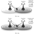
- FIG. 1(a) is a schematic diagram of a system framework of a signal sending method according to this application.
- the system framework includes a first base station, a second base station, and a terminal.
- FIG. 1(a) shows an application scenario of the signal sending method according to this application.
- a target cell accessed by the terminal is within coverage of the first base station
- a coordinating cell of the target cell is within coverage of the second base station
- the coverage of the first base station overlaps with the coverage of the second base station.
- Typical coverage with weak signal strength is overlapping coverage of the first base station and the second base station, and the weak signal strength may be caused by the following two factors: 1. Coverage of a base station is radiated from a center of the base station to outside, and consequently, overlapping coverage between base stations is far away from the base station; and 2. Overlapping coverage is covered by two or more base stations, and weak signal strength is caused by mutual interference between signals of the base stations.
- the first base station and the second base station coordinate to jointly send channel state information-reference signals, and the terminal measures and feeds back channel state information to the first base station, to perform joint transmission of downlink data information between the first base station and the second base station.
- a specific schematic diagram of the sending is shown in FIG. 1(b) .
- the first base station sends downlink control information and downlink data information to the terminal, and the second base station sends downlink data information to the terminal.
- FIG. 1(a) and FIG. 1(b) show a case in which the terminal with weak signal strength is located in an overlapping service area of the first base station and the second base station.
- the terminal may alternatively be located at another position with relatively weak signal strength, for example, in an edge area between two cells that are in coverage of a same base station.
- the coordinating cell may be one or more cells, and the terminal is within coverage of the one or more cells.
- the signal sending method in this application may be understood as a method for coordinately sending downlink data signals between cells, and an objective thereof is to improve signal strength of a terminal with relatively weak signal strength.
- the terminal with relatively weak signal strength is briefly referred to as a terminal in the following embodiments, and the following describes in detail the signal sending method in this application with reference to specific embodiments.
- the target cell is a serving cell of the terminal
- the terminal is a terminal with relatively weak signal strength in signal coverage of the target cell.
- the target cell and the coordinating cell perform joint transmission, to improve received signal strength of the terminal.
- an embodiment of the signal sending method according to an embodiment of this application includes the following steps.
- a first base station determines target pilot ports and a coordinating cell of a target cell, where the target pilot ports include a pilot port of the target cell and a pilot port of the coordinating cell.
- the target cell is a serving cell that provides a service for a terminal
- the coordinating cell is a cell that performs, with the target cell, joint transmission to the terminal.
- the first base station may periodically collect information about an A3 measurement report received by the first base station or another base station, and select, as coordinating cells, one or more cells that send a relatively large quantity of A3 measurement reports.
- the first base station determines a resource location of a target time-frequency resource.
- the first base station first obtains a cell identifier of the target cell, then the first base station determines a CSI-RS configuration index of the target cell based on the cell identifier of the target cell, and finally, the first base station determines the resource location of the target time-frequency resource based on the CSI-RS configuration index of the target cell, to determine the target time-frequency resource.
- the first base station may further perform the following operation: The first base station sends CSI-RS configuration information to the terminal, where the CSI-RS configuration information is used to indicate: a non-zero power CSI-RS configuration index of the terminal is the CSI-RS configuration index of the target cell, and a zero power CSI-RS configuration index of the terminal is an index indicating following three types of CSI-RS resource elements REs: an RE of a non-zero power CSI-RS of the terminal, an RE of a CSI-RS jointly delivered by the target cell for another target cell, and an RE of a CSI-RS jointly delivered by the coordinating cell for another target cell.
- the non-zero power CSI-RS configuration index and the zero power CSI-RS configuration index of the terminal are configured in the foregoing configuration manner.
- the first base station configures the non-zero power CSI-RS configuration index of the terminal as the CSI-RS configuration index of the target cell, so that the terminal can perform channel estimation only on a CSI-RS signal carried on the target time-frequency resource.
- the first base station configures the zero power CSI-RS configuration index of the terminal as the foregoing three types of indexes, so that when the target cell is updated, for example, is updated to the foregoing another target cell, the non-zero power CSI-RS configuration index of the terminal does not need to be reconfigured, and update efficiency is improved.
- the first base station adds the CSI-RSs of the target cell to the target time-frequency resource, and sends the CSI-RSs of the target cell to the terminal by using the target pilot ports.
- the terminal is a terminal whose signal quality strength is lower than a preset threshold.
- the coordinating cell determined in step 201 may be a cell covered by the first base station, for example, a neighboring cell of the target cell, or may be a cell covered by a second base station.
- the target pilot ports include both the pilot port of the target cell and the pilot port of the coordinating cell. Therefore, it is easily known that when the coordinating cell is covered by the first base station, the first base station may send a signal by using the pilot port of the target cell, and may send a signal by using the pilot port of the coordinating cell. However, when the coordinating cell is covered by the second base station, the first base station cannot send a signal by using the pilot port of the coordinating cell. In this case, the second base station needs to coordinate with the first base station to perform joint transmission.
- the target pilot ports include both the pilot port of the target cell and the pilot port of the coordinating cell
- the CSI-RSs of the target cell are jointly sent by the target cell and the coordinating cell, and resource locations of time-frequency resources used for joint transmission are the same, in other words, the resource locations each are the resource location of the target time-frequency resource corresponding to the target cell.
- the CSI-RSs of the target cell that are received by the terminal are the CSI-RSs of the target cell and are jointly delivered by the target cell and the coordinating cell by using a same time-frequency resource (namely, coherent joint transmission).
- the coherent joint transmission by the target cell and the coordinating cell may be implemented, so that phases of two signals (namely, signals separately corresponding to the target cell and the coordinating cell) received by the terminal may be superimposed on each other, to increase signal strength of the CSI-RSs received by the terminal, so that CSI of the target cell that is obtained by the terminal through measurement is more accurate, the target cell can obtain a larger gain when sending downlink data, and downlink data signal strength of the terminal is improved.
- the following describes in detail the signal sending method in this application with reference to two cases in which the coordinating cell and the target cell each belong to coverage of a same base station, and the coordinating cell and the target cell belong to coverage of different base stations.
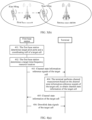
- FIG. 3(a) another embodiment of a signal sending method according to an embodiment of this application includes the following steps.
- a first base station determines target pilot ports and a coordinating cell of a target cell.
- the first base station determines the target pilot ports used for joint transmission by the target cell and the coordinating cell, the target pilot ports include a pilot port of the target cell and a pilot port of the coordinating cell, and the target cell is a cell covered by the first base station.
- the first base station determines the coordinating cell of the target cell, and a specific determining manner is: The first base station determines a second base station whose coverage overlaps with coverage of the first base station, and the first base station periodically collects an A3 measurement report received by the second base station, and uses, as coordinating cells, one or more cells that are covered by the second base station and that send a relatively large quantity of A3 measurement reports.
- a total quantity of the target pilot ports is S, and the S target pilot ports include A pilot ports of the target cell and (S-A) pilot ports of the coordinating cell, S is a positive integer not less than 2, a typical value of S is 8, 16, or 32, and A is a positive integer not less than 1 and less than S.
- the first base station determines a target time-frequency resource location.
- the first base station determines a target time-frequency resource, where the target time-frequency resource is a time-frequency resource that is corresponding to the target cell and that is used to jointly send channel state information-reference signals CSI-RSs of the target cell, and is also referred to as a time-frequency resource of the target cell.
- the target time-frequency resource is a time-frequency resource that is corresponding to the target cell and that is used to jointly send channel state information-reference signals CSI-RSs of the target cell, and is also referred to as a time-frequency resource of the target cell.
- the first base station determines a channel state information-reference signal configuration index CSI-RS configuration index of the target cell based on a cell identifier of the target cell.
- the CSI-RS configuration index is used to determine a frequency domain/time domain position for transmitting the CSI-RS, and a specific manner of determining the CSI-RS configuration index of the target cell may use (CellID mod N) as an index to determine the CSI-RS configuration index one by one, where N is an integer, and a typical value of N is 3 or 6.
- a fixed value may be used as an index to determine the CSI-RS configuration index of the target cell.
- the first base station configures a CSI-RS of the terminal:
- the first base station sends CSI-RS configuration information to the terminal, and performs the following configuration on the terminal: 1. configuring a non-zero power (non-zero power, NZP) CSI-RS configuration index of the terminal as the CSI-RS configuration index of the target cell; 2. configuring a quantity of non-zero power CSI-RS ports of the terminal to S, namely, a total quantity of pilot ports of the target cell and the coordinating cell; and 3.
- NZP non-zero power
- a zero power (zero power, ZP) CSI-RS configuration index of the terminal as an index indicating following CSI-RS resource elements (resource element, RE): 1. an RE of a non-zero power CSI-RS of the terminal; 2. an RE of a CSI-RS jointly delivered by the target cell for another target cell by using the target cell as a coordinating cell of the another target cell; and 3. an RE of a CSI-RS jointly delivered by the coordinating cell for another target cell.
- ZP zero power
- RE resource element
- the first base station sends a first notification message to the second base station.
- the first base station After determining the time-frequency resource location of the target cell, the first base station sends the first notification message to the second base station.
- the first notification message carries a cell identifier of the coordinating cell, so that the second base station sends, on the (S-A) pilot ports of the coordinating cell, the CSI-RS of the target cell to the terminal based on the time-frequency resource indicated by the time-frequency resource location of the target cell.
- the first base station sends, on the pilot port of the target cell, the channel state information-reference signal of the target cell to the terminal based on the target time-frequency resource location.
- the first base station sends, to the terminal on the A pilot ports of the target cell, the CSI-RS in the target time-frequency resource of the target cell, namely, the CSI-RS of the target cell.
- the target time-frequency resource location is indicated by the CSI-RS configuration index of the target cell.
- the method further includes: The first base station determines the terminal.
- a specific determining method may be: The first base station selects a terminal in an overlapping service area between the target cell of the first base station and the coordinating cell of the second base station as the terminal.
- the terminal actively sends an A3 measurement report to the base station, and therefore, the A3 measurement report may be used as a basis for selecting a terminal with poor signal quality by the base station.
- the second base station sends, on the pilot port of the coordinating cell, the channel state information-reference signal of the target cell to the terminal based on the target time-frequency resource location.
- the second base station sends, to the terminal on the (S-A) pilot ports of the coordinating cell, the CSI-RS in the target time-frequency resource of the target cell, namely, the CSI-RS of the target cell.
- the target time-frequency resource location is indicated by the CSI-RS configuration index of the target cell.
- the first base station sends, on pilot ports whose port numbers are 0 to 3, CSI-RSs of the target cell to the terminal, and the second base station sends, on pilot ports whose port numbers are 4 to 7, CSI-RSs of the target cell to the terminal.
- the terminal performs channel measurement based on the channel state information-reference signal of the target cell, to obtain channel state information of the target cell.
- the terminal performs the channel measurement based on the received CSI-RS of the target cell, to obtain the channel state information CSI of the target cell.
- the CSI includes a channel quality indication (channel quality indication, CQI), a channel rank indication (rank indication, RI), and a precoding matrix indication (precoding matrix indication, PMI).
- CQI channel quality indication
- RI channel rank indication
- PMI precoding matrix indication
- the CQI is a fixed table in LTE, and usually, a higher SINR indicates a higher CQI order and a higher user rate.
- the PMI is calculated by the terminal through the channel measurement, and is fed back to the base station; and the base station performs transmission precoding by using the PMI, to better perform matching between the PMI and a channel and obtain a precoding gain.
- the RI indicates a quantity of multiplexed streams supported by a channel.
- the first base station configures a transmission mode of the terminal as TM9. Because a quantity of ports in the PMI measured by the terminal is the same as a quantity of NZP CSI-RS ports configured for the terminal, and the PMI is weighted to a PDSCH of TM9, a quantity of ports used for sending the PDSCH is the same as the quantity of NZP CSI-RS ports configured for the terminal.
- the terminal sends the channel state information of the target cell to the first base station.
- the terminal reports the CSI of the target cell to the first base station, and the CSI includes the CQI, the PMI, and the RI.
- the first base station sends a second notification message to the second base station based on the channel state information of the target cell.
- the first base station determines, based on the CQI, the PMI, and the RI that are fed back by the terminal, a modulation and coding scheme (modulation and coding scheme, MCS), a rank, and a PMI of the PDSCH channel sent to the terminal, and the first base station sends, to the second base station, the second notification message that carries the MCS, the rank, the PMI, and downlink data information.
- MCS modulation and coding scheme
- the first base station sends a downlink data signal of the target cell to the terminal based on the channel state information of the target cell.
- the first base station determines, based on the CQI, the PMI, and the RI that are fed back by the terminal, the MCS, the RANK, and the PMI of the PDSCH channel sent to the terminal, and sends, on A data ports, the PDSCH channel that carries the downlink data information.
- the A data ports have a one-to-one correspondence with the A pilot ports of the target cell, and a data port and a corresponding pilot port correspond to a same physical antenna.
- a transmission mode of the PDSCH channel is TM9. It can be learned from the description in step 306 that the quantity of ports used for sending the PDSCH of TM9 is the same as the quantity of NZP CSI-RS ports configured for the terminal, and it can be learned from step 302 that the quantity of NZP CSI-RS ports configured for the terminal is the same as the quantity S of the target pilot ports. Therefore, the first base station sends, to the terminal on the A pilot ports of the target cell, the PDSCH of TM9.
- the first base station sends, to the terminal, a PDCCH corresponding to the PDSCH of TM9, where the PDCCH is used to carry downlink control information for assisting in demodulating the downlink data information.
- the second base station sends a downlink data signal of the target cell to the terminal based on the channel state information-reference signal of the target cell.
- the second base station After the second base station receives the second notification message sent by the first base station, the second base station generates a PDSCH channel based on the MCS, the RANK, and the PMI that are carried in the second notification message, adds the downlink data information to the PDSCH channel, and sends, on (S-A) data ports, the PDSCH channel to the terminal.
- a pilot port and a corresponding data port correspond to a same physical antenna.
- the second base station sends, on the (S-A) pilot ports of the coordinating cell, the PDSCH of TM9 to the terminal.
- a sending manner in which the first base station and the second base station send the downlink control information of the target cell to the terminal in step 309 and step 310 is similar to the sending manner in which the CSI-RS of the target cell is sent in step 305.
- the first base station and the second base station separately send the CSI-RSs to the terminal on the pilot ports of the target cell and the coordinating cell according to an instruction of the same CSI-RS configuration index, to implement joint transmission performed by the target cell and the coordinating cell by using a joint channel, so that the target terminal obtains more accurate channel state information through measurement, and obtains a larger coherent transmission gain.
- the transmit weight PMI fed back based on the CSI-RSs sent by using the joint channel is weighted to the PDSCH of TM9, so that when PDSCHs sent by the first base station and the second base station arrive at the terminal, the PDSCHs of the first base station and the second base station have a same phase. Therefore, phase superimposition may be performed to enhance signal strength, and signal strength of a received signal of the terminal is improved.
- Application scenario 1 As shown in FIG. 3(b) , Xiao Ming uses a mobile phone to make a call with another person. When the call starts, Xiao Ming makes the call within a service range of the first base station, and a voice service is performed between the mobile phone and the first base station.
- Xiao Ming moves in a direction of an arrow in the figure while making the call, and when Xiao Ming moves to an overlapping service area between the first base station and the second base station in the figure, because signal strength of the mobile phone is weak due to interference from the second base station and a long distance from the first base station, the mobile phone starts to detect, through measurement, that surrounding signal strength of the second base station is relatively strong, and sends an A3 measurement report to the first base station to request to be handed over.
- the first base station determines the mobile phone as a terminal, and the first base station sends a notification message to the second base station, to instruct the second base station to assist the first base station in sending voice signals to the mobile phone of Xiao Ming.
- the first base station After the first base station and the second base station complete information exchange for joint transmission, the first base station sends the voice signals to the mobile phone of Xiao Ming in coordination with the second base station, to enhance the signal strength of the mobile phone of Xiao Ming and ensure a normal call.
- FIG. 4(a) another embodiment of a signal sending method according to an embodiment of this application includes the following steps.
- a first base station determines target pilot ports and a coordinating cell of a target cell.
- the first base station determines the target pilot ports used for joint transmission by the target cell and the coordinating cell, the target pilot ports include a pilot port of the target cell and a pilot port of the coordinating cell, and the target cell is a cell covered by the first base station.
- the first base station uses one or more neighboring cells of the target cell as coordinating cells. For example, three neighboring sectors of a base station may be fixedly coordinating cells of each other.
- the first base station determines a target time-frequency resource location.
- Step 402 is similar to step 302. For detailed descriptions, refer to step 302. Details are not described herein again.
- the first base station sends, on the pilot port of the target cell and the pilot port of the coordinating cell, channel state information-reference signals of the target cell to a terminal based on the target time-frequency resource location.
- the first base station sends, to the terminal on A pilot ports of the target cell and (S-A) pilot ports of the coordinating cell, the CSI-RSs in the target time-frequency resource, namely, the CSI-RSs of the target cell, the target time-frequency resource location is indicated by the CSI-RS configuration index of the target cell.
- step 403 is similar to the related descriptions of step 304 and step 305.
- step 304 and step 305 For detailed descriptions, refer to the related descriptions of step 304 and step 305. Details are not described herein again.
- the method further includes:
- the first base station uses a terminal with relatively weak signal strength at an edge position of the target cell and the coordinating cell as the terminal.
- a specific determining method thereof may also be based on an A3 measurement report reported by the terminal to the base station. For detailed descriptions, refer to related descriptions of the A3 measurement in step 304. Details are not described herein again.
- the terminal performs channel measurement based on the channel state information-reference signals of the target cell, to obtain channel state information of the target cell.
- the terminal sends the channel state information of the target cell to the first base station.
- Step 404 and step 405 are respectively similar to step 306 and step 307.
- Step 404 and step 405 are respectively similar to step 306 and step 307.
- the first base station sends downlink data signals of the target cell to the terminal based on the channel state information of the target cell.
- Step 406 is similar to the related descriptions in step 309 and step 310. A difference lies in that, because the coordinating cell and the target cell are both within the coverage of the first base station, the first base station in step 406 needs to perform not only the operation of the first base station in step 309, but also the operation of the second base station in step 310. For related descriptions of other parts, refer to the foregoing step 309 and step 310. Details are not described herein again.
- the target cell and the coordinating cell are covered by a same base station, and joint coherent transmission is performed by the target cell and the coordinating cell, so that when PDSCHs sent by using the pilot port of the target cell and the pilot port of the coordinating cell arrive at the terminal, the PDSCHs with a same phase may be superimposed with each other, to improve signal strength of received signals of the terminal and improve the downlink data transmission efficiency.
- the following provides detailed descriptions with reference to a specific application scenario.
- Application scenario 2 As shown in FIG. 4(b) , a cell 1, a cell 2, and a cell 3 are three neighboring cells covered by a base station, and the three cells are coordinating cells of each other.
- Xiao Ming uses a mobile phone to make a call with another person. When the call starts, Xiao Ming is in a service range of the serving cell 1 of the base station, and voice transmission is performed between the serving cell 1 and the mobile phone. Xiao Ming moves towards an edge service area of the cell 3 and the cell 1 in a direction of an arrow in the figure while making the call, and finally continues to make the call at the position at the tail of the arrow.
- the cell 1 instructs the cell 3 to perform joint transmission to the mobile phone of Xiao Ming, and then the cell 1 coordinates with the cell 3 to jointly send voice signals to the mobile phone of Xiao Ming, to enhance the signal strength of the mobile phone of Xiao Ming and ensure a normal call.
- the signal sending methods in this application are described in detail from a perspective that the coordinating cell and the target cell are covered by a same base station or by different base stations.
- the following describes in detail the first base station, the second base station, and the terminal in this application. Details are as follows:
- a first base station 50 in an embodiment of this application includes:
- the processing module 501 is specifically configured to:
- the sending module 502 is further configured to: send CSI-RS configuration information to the terminal, where the CSI-RS configuration information is used to indicate: a non-zero power CSI-RS configuration index of the terminal is the CSI-RS configuration index of the target cell, and a zero power CSI-RS configuration index of the terminal is an index indicating following three types of CSI-RS resource elements REs: an RE of a non-zero power CSI-RS of the terminal, an RE of a CSI-RS jointly delivered by the target cell for another target cell, and an RE of a CSI-RS jointly delivered by the coordinating cell for another target cell.
- the coordinating cell is a cell covered by the first base station, and a total quantity of the target pilot ports is S, where a quantity of pilot ports of the target cell is A, a quantity of pilot ports of the coordinating cell is (S-A), S is a positive integer not less than 2, and A is a positive integer not less than 1 and less than S; and the processing module 601 is specifically configured to: send, on the A pilot ports of the target cell and the (S-A) pilot ports of the coordinating cell, the CSI-RSs of the target cell to the terminal based on the target time-frequency resource.
- the first base station 60 further includes:
- the coordinating cell is a cell covered by a second base station
- the second base station is a base station whose coverage overlaps coverage of the first base station
- a total quantity of the target pilot ports is S, where a quantity of pilot ports of the coordinating cell is (S-A), S is a positive integer not less than 2, and A is a positive integer not less than 1 and less than S
- the sending module 602 is further configured to:
- the first base station 60 further includes:
- first base station separately uses reference numeral 50 and 60, which are merely used to distinguish whether the first base station is the first base station shown in FIG. 5 or the first base station is shown in FIG. 6 . There is no other difference.
- 50 is used to identify the first base station. Details are not described below again.
- the processing module 501 may be specifically a processor 901 shown in FIG. 9
- a second base station 70 in an embodiment of this application includes:
- the receiving module 701 is further configured to:
- the processing module 702 may be specifically a processor 1001 shown in FIG. 10
- the receiving module 701 and the sending module 703 may be specifically a transceiver 1002 shown in FIG. 10 .
- a terminal 80 in an embodiment of this application includes:
- the receiving module 801 is further configured to: receive CSI-RS configuration information sent by the first base station, where the CSI-RS configuration information is used to indicate: a non-zero power channel state information-reference signal CSI-RS configuration index of the terminal is a CSI-RS configuration index of the target cell, where the CSI-RS configuration index of the target cell is used to determine the target time-frequency resource, and the CSI-RS configuration index of the target cell is determined based on a cell identifier of the target cell; a zero power CSI-RS configuration index of the terminal is an index indicating following three types of CSI-RS resource elements REs: an RE of a non-zero power CSI-RS of the terminal, an RE of a CSI-RS jointly delivered by the target cell for another target cell, and an RE of a CSI-RS jointly delivered by the coordinating cell for another target cell.
- the processing module 802 may be specifically a processor 111 shown in FIG. 11
- the receiving module 801 and the sending module 803 may be specifically a transceiver 112 shown in FIG. 11 .
- a first base station 90 includes: a transceiver 902, a processor 901, a memory 903, and a network interface 904.
- the first base station 90 provides wireless access from UE to a network, and includes one or more processors 901, one or more memories 903, one or more network interfaces 904, and one or more transceivers 902 (each transceiver includes a receiver Rx and a transmitter Tx) that are connected by using a bus.
- the one or more transceivers 902 are connected to an antenna or an antenna array.
- the one or more processors 901 include computer program code or a computer operation instruction.
- the network interface 904 is connected to a core network device 91 by using a link (for example, a link between the network interface 904 and a core network), or is connected to another base station (for example, a second base station 100) by using a wired or wireless link.
- the processor 901 invokes the computer program code or the computer operation instruction stored in the memory 902, to perform related operations of the first base station in FIG. 3(a) and FIG. 4(a) .
- the processor 901 invokes the computer program code or the computer operation instruction stored in the memory 902, to perform related operations of the first base station in FIG. 3(a) and FIG. 4(a) .
- the processor 901 invokes the computer program code or the computer operation instruction stored in the memory 902, to perform related operations of the first base station in FIG. 3(a) and FIG. 4(a) .
- the processor 901 invokes the computer program code or the computer operation instruction stored in the memory 902, to perform related operations of the first base station in FIG. 3(a) and FIG. 4(a) .
- the network may further include the core network device 91, for example, a network control unit (network control equipment, NCE), a mobility management entity (mobile management entity, MME), or a signaling gateway (signaling gateway, SGW), and may further provide a network connection, for example, a connection to a telephone network and/or a data communications network (for example, the internet).
- the first base station 90 may be connected to the core network device 91 by using a link (for example, an S1 interface).
- the core network device 91 includes one or more processors 911, one or more memories 912, and one or more network interfaces 913 that are connected by using a bus.
- the one or more memories 912 include computer program code or a computer operation instruction.
- An embodiment of this application further provides a computer storage medium, configured to store a computer software instruction used by the foregoing first base station.
- the computer software instruction is run on a computer, the computer is enabled to perform the signal sending method performed by the first base station 90.
- the storage medium may be specifically the memory 912.
- An embodiment of this application further provides a computer program product including an instruction.
- the computer program product When the computer program product is run on a computer, the computer is enabled to perform the signal sending method performed by the first base station.
- a second base station 100 includes: a transceiver 1002, a processor 1001, a memory 1003, and a network interface 1004.
- the second base station 100 provides wireless access from UE to a network, and includes one or more processors 1001, one or more memories 1003, one or more network interfaces 1004, and one or more transceivers 1002 (each transceiver includes a receiver Rx and a transmitter Tx) that are connected by using a bus.
- the one or more transceivers 1002 are connected to an antenna or an antenna array.
- the one or more processors 1001 include computer program code or a computer operation instruction.
- the network interface 1004 is connected to a core network device 110 by using a link (for example, a link between the network interface 1004 and a core network), or is connected to another base station (for example, a first base station 90) by using a wired or wireless link.
- the processor 1001 invokes the computer program code or the computer operation instruction stored in the memory 1002, to perform related operations of the second base station in FIG. 4(a) .
- the processor 1001 invokes the computer program code or the computer operation instruction stored in the memory 1002, to perform related operations of the second base station in FIG. 4(a) .
- the processor 1001 invokes the computer program code or the computer operation instruction stored in the memory 1002, to perform related operations of the second base station in FIG. 4(a) .
- the processor 1001 invokes the computer program code or the computer operation instruction stored in the memory 1002, to perform related operations of the second base station in FIG. 4(a) .
- the network may further include the core network device 110, for example, a network control unit (network control equipment, NCE), a mobility management entity (mobile management entity, MME), or a signaling gateway (signaling gateway, SGW), and may further provide a network connection, for example, a connection to a telephone network and/or a data communications network (for example, the internet).
- the second base station 100 may be connected to the core network device 110 by using a link (for example, an S1 interface).
- the core network device 110 includes one or more processors 1101, one or more memories 1102, and one or more network interfaces 1103 that are connected by using a bus.
- the one or more memories 1102 include computer program code or a computer operation instruction.
- An embodiment of this application further provides a computer storage medium, configured to store a computer software instruction used by the foregoing second terminal.
- the computer software instruction is run on a computer, the computer is enabled to perform the signal sending method performed by the second base station 100.
- the storage medium may be specifically the memory 1002.
- An embodiment of this application further provides a computer program product including an instruction.
- the computer program product When the computer program product is run on a computer, the computer is enabled to perform the signal sending method performed by the terminal.
- a terminal 11 includes: a processor 111, a transceiver 112, and a memory 113.
- the terminal 11 is referred to as UE 11, and performs wireless communication with a base station by using a link.
- the UE 11 includes one or more processors 111, one or more memories 113, and one or more transceivers 112 (each transceiver includes a transmitter Tx and a receiver Rx) that are connected by using a bus.
- the one or more transceivers 112 are connected to one or more antennas.
- the one or more memories 113 include computer program code or a computer operation instruction.
- the processor 111 invokes the computer program code or the computer operation instruction stored in the memory 113, to perform related operations of the terminal in FIG. 3(a) and FIG. 4(a) .
- the processor 111 invokes the computer program code or the computer operation instruction stored in the memory 113, to perform related operations of the terminal in FIG. 3(a) and FIG. 4(a) .
- An embodiment of this application further provides a computer storage medium, configured to store a computer software instruction used by the foregoing terminal. When the computer software instruction is run on a computer, the computer is enabled to perform the signal sending method performed by the terminal 11.
- the storage medium may be specifically the memory 113.
- An embodiment of this application further provides a computer program product including an instruction.
- the computer program product When the computer program product is run on a computer, the computer is enabled to perform the signal sending method performed by the terminal.
- An embodiment of this application further provides a communications apparatus.
- the communications apparatus includes a processing element and a storage element.
- the storage element is configured to store a computer program, and when the processing element invokes the computer program, the communications apparatus is configured to perform the operations performed by the terminal, the first base station, or the second base station in the foregoing signal sending method embodiments.
- the base station may be any base station mentioned above, or the UE may be any terminal mentioned above. This is not limited herein.
- the memories included in the UE, the base station, and the core network device may be of a type suitable for any local technology environment, and may be implemented by using any suitable data storage technology.
- All or some of the foregoing embodiments may be implemented by using software, hardware, firmware, or any combination thereof.
- the embodiments may be implemented completely or partially in a form of a computer program product.
- the computer program product includes one or more computer instructions.
- the computer may be a general-purpose computer, a dedicated computer, a computer network, or another programmable apparatus.
- the computer instructions may be stored in a computer-readable storage medium or may be transmitted from a computer-readable storage medium to another computer-readable storage medium.
- the usable medium may be a magnetic medium (for example, a floppy disk, a hard disk, or a magnetic tape), an optical medium (for example, a DVD), a semiconductor medium (for example, a solid-state drive solid state disk (SSD)), or the like.
- a magnetic medium for example, a floppy disk, a hard disk, or a magnetic tape
- an optical medium for example, a DVD
- a semiconductor medium for example, a solid-state drive solid state disk (SSD)
- the disclosed system, apparatus, and method may be implemented in other manners.
- the described apparatus embodiment is merely an example.
- the unit division is merely logical function division and may be other division in actual implementation.
- a plurality of units or components may be combined or integrated into another system, or some features may be ignored or not performed.
- the displayed or discussed mutual couplings or direct couplings or communication connections may be implemented by using some interfaces.
- the indirect couplings or communication connections between the apparatuses or units may be implemented in electronic, mechanical, or other forms.
- the units described as separate parts may or may not be physically separate, and parts displayed as units may or may not be physical units, may be located in one position, or may be distributed on a plurality of network units. Some or all of the units may be selected based on actual requirements to achieve the objectives of the solutions of the embodiments.
- functional units in the embodiments of this application may be integrated into one processing unit, or each of the units may exist alone physically, or two or more units are integrated into one unit.
- the integrated unit may be implemented in a form of hardware, or may be implemented in a form of a software functional unit.
- the integrated unit When the integrated unit is implemented in the form of a software functional unit and sold or used as an independent product, the integrated unit may be stored in a computer-readable storage medium. Based on such an understanding, the technical solutions of this application essentially, or the part contributing to the prior art, or all or some of the technical solutions may be implemented in a form of a software product.
- the software product is stored in a storage medium and includes several instructions for instructing a computer device (which may be a personal computer, a server, or a network device) to perform all or some of the steps of the methods described in the embodiments of this application.
- the foregoing storage medium includes: any medium that can store program code, such as a USB flash drive, a removable hard disk, a read-only memory (read-only memory, ROM), a random access memory (random access memory, RAM), a magnetic disk, or an optical disc.
- program code such as a USB flash drive, a removable hard disk, a read-only memory (read-only memory, ROM), a random access memory (random access memory, RAM), a magnetic disk, or an optical disc.
Landscapes
- Engineering & Computer Science (AREA)
- Signal Processing (AREA)
- Computer Networks & Wireless Communication (AREA)
- Mobile Radio Communication Systems (AREA)
Claims (4)
- Signalsendeverfahren, umfassend:Bestimmen (201, 301, 401), durch eine erste Basisstation, von Zielsteueranschlüssen und einer koordinierenden Zelle einer bedienenden Zelle eines Endgerätes, wobei die koordinierende Zelle eine Zelle ist, die gemeinsam mit der bedienenden Zelle ein Kanalzustandsinformationen-Referenzsignal, CSI-RS, der bedienenden Zelle sendet, die Zielsteueranschlüsse Steueranschlüsse sind, die zum gemeinsamen Senden des CSI-RS der bedienenden Zelle verwendet werden, und die Zielsteueranschlüsse einen Steueranschluss der bedienenden Zelle und einen Steueranschluss der koordinierenden Zelle umfassen;Bestimmen (202, 302, 402), durch die erste Basisstation, eines Ressourcenstandortes einer Ziel-Zeit-Frequenz-Ressource, wobei die Ziel-Zeit-Frequenz-Ressource eine Zeit-Frequenz-Ressource ist, die zum Senden des CSI-RS der bedienenden Zelle verwendet wird; undSenden (203, 304, 403), durch die erste Basisstation an dem Steueranschluss der bedienenden Zelle, des CSI-RS der bedienenden Zelle an das Endgerät basierend auf der Ziel-Zeit-Frequenz-Ressource, wobeidie bedienende Zelle eine Zelle ist, die durch die erste Basisstation abgedeckt wird, die koordinierende Zelle eine Zelle ist, die durch eine zweite Basisstation abgedeckt wird, die zweite Basisstation eine Basisstation ist, deren Abdeckung sich mit der Abdeckung der ersten Basisstation überlappt, und eine Gesamtanzahl der Zielsteueranschlüsse S ist, eine Anzahl von Steueranschlüssen der bedienenden Zelle A ist, eine Anzahl von Steueranschlüssen der koordinierenden Zelle (S-A) ist, S eine positive Ganzzahl nicht kleiner als 2 ist und A eine positive Ganzzahl nicht kleiner als 1 und kleiner als S ist;vor dem Senden (304), durch die erste Basisstation an dem Steueranschluss der bedienenden Zelle, des CSI-RS der bedienenden Zelle an das Endgerät basierend auf der Ziel-Zeit-Frequenz-Ressource das Verfahren ferner Folgendes umfasst:Auswählen, durch die erste Basisstation, eines Endgerätes in einem überlappenden Dienstbereich zwischen der bedienenden Zelle der ersten Basisstation und der koordinierenden Zelle der zweiten Basisstation als das Endgerät basierend auf einem von dem Endgerät an der ersten Basisstation empfangenen A3-Messbericht, wobei eine Signalstärke der bedienenden Zelle des ausgewählten Endgerätes niedriger als ein zuvor festgelegter Schwellenwert ist;vor dem Senden (304), durch die erste Basisstation an dem Steueranschluss der bedienenden Zelle, des CSI-RS der bedienenden Zelle an das Endgerät basierend auf der Ziel-Zeit-Frequenz-Ressource das Verfahren ferner Folgendes umfasst:Senden (303), durch die erste Basisstation, einer ersten Benachrichtigungsnachricht an die zweite Basisstation, wobei die erste Benachrichtigungsnachricht eine Zellenkennung der koordinierenden Zelle befördert; unddas Senden (304), durch die erste Basisstation an dem Steueranschluss der bedienenden Zelle, des CSI-RS der bedienenden Zelle an das Endgerät basierend auf der Ziel-Zeit-Frequenz-Ressource speziell Folgendes umfasst:Senden (304), durch die erste Basisstation an den A Steueranschlüssen der bedienenden Zelle, des CSI-RS der bedienenden Zelle an das Endgerät basierend auf der Ziel-Zeit-Frequenz-Ressource,wobei nach dem Senden (304), durch die erste Basisstation an den A Steueranschlüssen der bedienenden Zelle, des CSI-RS der bedienenden Zelle an das Endgerät basierend auf der Ziel-Zeit-Frequenz-Ressource das Verfahren ferner Folgendes umfasst:Empfangen (307), durch die erste Basisstation, von CSI der bedienenden Zelle, die durch das Endgerät gesendet werden;Senden (308), durch die erste Basisstation, einer zweiten Benachrichtigungsnachricht an die zweite Basisstation, wobei die zweite Benachrichtigungsnachricht die CSI der bedienenden Zelle und ein Downlink-Datensignal der bedienenden Zelle befördert, sodass die zweite Basisstation an (S-A) Datenanschlüssen das Downlink-Datensignal der bedienenden Zelle an das Endgerät basierend auf den CSI der bedienenden Zelle sendet, wobei die (S-A) Datenanschlüsse eine Eins-zu-eins-Entsprechung mit den (S-A) Steueranschlüssen der koordinierenden Zelle aufweisen; undSenden (309), durch die erste Basisstation an A Datenanschlüssen, eines Downlink-Datensignals der bedienenden Zelle an das Endgerät basierend auf den CSI der bedienenden Zelle, wobei die A Datenanschlüsse eine Eins-zu-eins-Entsprechung mit den A Steueranschlüssen der bedienenden Zelle aufweisen, wobei ein Datenanschluss und ein entsprechender Steueranschluss derselben physischen Antenne entsprechen,wobei A ungleich (S-A) ist,wobei das Verfahren ferner Empfangen (303), durch die zweite Basisstation, der durch die erste Basisstation gesendeten ersten Benachrichtigungsnachricht umfasst;
undSenden (305), durch die zweite Basisstation an den (S-A) Steueranschlüssen der koordinierenden Zelle, des CSI-RS der bedienenden Zelle an das Endgerät basierend auf der Ziel-Zeit-Frequenz-Ressource,wobei nach dem Senden (305), durch die zweite Basisstation an den (S-A) Steueranschlüssen der koordinierenden Zelle, des CSI-RS der bedienenden Zelle an das Endgerät basierend auf der Ziel-Zeit-Frequenz-Ressource das Verfahren ferner Folgendes umfasst:Empfangen (308), durch die zweite Basisstation, der durch die erste Basisstation gesendeten zweiten Benachrichtigungsnachricht; undSenden (310), durch die zweite Basisstation an (S-A) Datenanschlüssen, des Downlink-Datensignals der bedienenden Zelle an das Endgerät basierend auf den CSI der bedienenden Zelle, wobei die (S-A) Datenanschlüsse eine Eins-zu-eins-Entsprechung mit den (S-A) Steueranschlüssen der bedienenden Zelle aufweisen, wobei ein Datenanschluss und ein entsprechender Steueranschluss derselben physischen Antenne entsprechen. - Verfahren nach Anspruch 1, wobei das Bestimmen (202, 302, 402), durch die erste Basisstation, eines Ressourcenstandortes einer Ziel-Zeit-Frequenz-Ressource speziell Folgendes umfasst:Bestimmen, durch die erste Basisstation, eines CSI-RS-Konfigurationsindex der bedienenden Zelle basierend auf einer Zellenkennung der bedienenden Zelle; undBestimmen, durch die erste Basisstation, des Ressourcenstandortes der Ziel-Zeit-Frequenz-Ressource basierend auf dem CSI-RS-Konfigurationsindex der bedienenden Zelle; undnach dem Bestimmen, durch die erste Basisstation, eines CSI-RS-Konfigurationsindex der bedienenden Zelle basierend auf einer Zellenkennung der bedienenden Zelle das Verfahren Folgendes umfasst:
Senden, durch die erste Basisstation, von CSI-RS-Konfigurationsinformationen an das Endgerät, wobei die CSI-RS-Konfigurationsinformationen verwendet werden, um Folgendes anzugeben: ein von Nullleistung verschiedener CSI-RS-Konfigurationsindex des Endgerätes ist der CSI-RS-Konfigurationsindex der bedienenden Zelle und ein CSI-RS-Konfigurationsindex mit Nullleistung des Endgerätes ist ein Index, der einen der folgenden drei Typen von CSI-RS-Ressourcenelementen REs angibt: ein RE eines von Nullleistung verschiedenen CSI-RS des Endgerätes, ein RE eines durch die bedienende Zelle für eine andere bedienende Zelle abgegebenen CSI-RS und ein RE eines durch die koordinierende Zelle für eine andere bedienende Zelle abgegebenen CSI-RS. - System, umfassend eine erste Basisstation und eine zweite Basisstation, wobei die erste Basisstation und die zweite Basisstation dazu konfiguriert sind, das Verfahren nach einem der Ansprüche 1 bis 2 durchzuführen.
- Computerlesbarer Speicher, der dazu konfiguriert ist, Programmcode zu speichern, und wobei der Programmcode eine Anweisung beinhaltet, die bei Ausführung des Programms durch ein System nach Anspruch 3 die erste Basisstation und die zweite Basisstation dazu veranlasst, das Verfahren nach einem der Ansprüche 1 bis 2 durchzuführen.
Applications Claiming Priority (1)
| Application Number | Priority Date | Filing Date | Title |
|---|---|---|---|
| PCT/CN2018/074546 WO2019148314A1 (zh) | 2018-01-30 | 2018-01-30 | 一种信号发送方法及相关设备 |
Publications (3)
| Publication Number | Publication Date |
|---|---|
| EP3737205A1 EP3737205A1 (de) | 2020-11-11 |
| EP3737205A4 EP3737205A4 (de) | 2021-02-24 |
| EP3737205B1 true EP3737205B1 (de) | 2025-04-23 |
Family
ID=67477849
Family Applications (1)
| Application Number | Title | Priority Date | Filing Date |
|---|---|---|---|
| EP18904302.9A Active EP3737205B1 (de) | 2018-01-30 | 2018-01-30 | Signalübertragungsverfahren und zugehörige vorrichtung |
Country Status (5)
| Country | Link |
|---|---|
| US (1) | US11394444B2 (de) |
| EP (1) | EP3737205B1 (de) |
| CN (1) | CN111656856B (de) |
| BR (1) | BR112020015357A2 (de) |
| WO (1) | WO2019148314A1 (de) |
Families Citing this family (10)
| Publication number | Priority date | Publication date | Assignee | Title |
|---|---|---|---|---|
| CN113748632B (zh) * | 2019-04-25 | 2023-05-05 | 华为技术有限公司 | 信道状态信息参考信号的配置方法和装置 |
| US10993150B2 (en) * | 2019-05-22 | 2021-04-27 | At&T Intellectual Property I, L.P. | Wireless control plane having centralized and distributed control messages |
| CN112073163B (zh) * | 2019-06-11 | 2021-11-02 | 中国电信股份有限公司 | 邻小区配置信息传输方法和系统、计算机可读存储介质 |
| CN113949421B (zh) * | 2020-07-17 | 2023-02-24 | 维沃移动通信有限公司 | 确定波束信息的方法、装置及电子设备 |
| US11503526B2 (en) * | 2020-09-15 | 2022-11-15 | International Business Machines Corporation | Predictive communication compensation |
| CN116567683A (zh) * | 2022-01-27 | 2023-08-08 | 中国移动通信有限公司研究院 | 一种信息采集方法、终端及计算机可读存储介质 |
| CN116707594B (zh) * | 2022-02-24 | 2026-03-20 | 大唐移动通信设备有限公司 | 一种信道状态信息测量方法、装置、电子设备及存储介质 |
| CN116669059B (zh) * | 2023-07-18 | 2025-12-30 | 中国联合网络通信集团有限公司 | 发射端口数确定方法、装置及存储介质 |
| CN116684892B (zh) * | 2023-07-18 | 2026-03-06 | 中国联合网络通信集团有限公司 | 发射端口数确定方法、装置及存储介质 |
| CN119232219B (zh) * | 2024-11-29 | 2025-03-14 | 深圳捷扬微电子有限公司 | Uwb终端设备的天线自适应切换方法及计算机可读存储介质 |
Citations (2)
| Publication number | Priority date | Publication date | Assignee | Title |
|---|---|---|---|---|
| US20130322288A1 (en) * | 2011-02-17 | 2013-12-05 | Alcatel Lucent | Method of determining a channel state in coordinated multipoint transmission |
| US20160081082A1 (en) * | 2014-09-12 | 2016-03-17 | Parallel Wireless, Inc. | Low-Latency Inter-eNodeB Coordinated Multi-Point Transmission |
Family Cites Families (19)
| Publication number | Priority date | Publication date | Assignee | Title |
|---|---|---|---|---|
| US8547954B2 (en) * | 2008-08-28 | 2013-10-01 | Qualcomm Incorporated | Methods and apparatus of adapting number of advertised transmit antenna ports |
| CN102111879B (zh) | 2009-12-29 | 2014-07-02 | 中国移动通信集团公司 | 分配资源、发送信道状态信息导频信号的方法及设备 |
| CN103339871A (zh) * | 2011-02-02 | 2013-10-02 | 富士通株式会社 | 利用协作小区的无线通信 |
| US8953478B2 (en) * | 2012-01-27 | 2015-02-10 | Intel Corporation | Evolved node B and method for coherent coordinated multipoint transmission with per CSI-RS feedback |
| KR20150035759A (ko) * | 2012-06-29 | 2015-04-07 | 엘지전자 주식회사 | 무선 통신 시스템에서 csi-rs 측정 및 보고 방법 및 이를 지원하는 장치 |
| JP2014027626A (ja) * | 2012-07-30 | 2014-02-06 | Sharp Corp | 通信システム、通信方法、基地局装置及び移動局装置 |
| US9106386B2 (en) * | 2012-08-03 | 2015-08-11 | Intel Corporation | Reference signal configuration for coordinated multipoint |
| WO2014035137A1 (ko) * | 2012-08-30 | 2014-03-06 | 엘지전자 주식회사 | 무선 통신 시스템에서 채널을 추정하는 방법 및 장치 |
| US11139862B2 (en) * | 2012-11-02 | 2021-10-05 | Samsung Electronics Co., Ltd. | Configuration of rate matching and interference measurement resources for coordinated multi-point transmission |
| JP6256610B2 (ja) * | 2013-08-09 | 2018-01-10 | 富士通株式会社 | 情報交換方法、基地局及び通信システム |
| CN104618985B (zh) * | 2013-11-01 | 2019-09-24 | 中兴通讯股份有限公司 | 设备发现信号的发送方法、装置、设备及系统 |
| CN105025519B (zh) * | 2014-04-30 | 2019-06-14 | 电信科学技术研究院 | 干扰信号测量方法及相关设备 |
| CN105846950A (zh) * | 2015-01-15 | 2016-08-10 | 中兴通讯股份有限公司 | 相干jt的实现方法和装置 |
| EP3252983A4 (de) * | 2015-01-30 | 2018-10-03 | Electronics and Telecommunications Research Institute | Verfahren und vorrichtung zur übertragung eines downlink-referenzsignals sowie verfahren und vorrichtung zur übertragung von steuerungsinformationen in mehrzelligem kollaborativem kommunikationssystem |
| CN105992367B (zh) | 2015-03-06 | 2019-07-12 | 普天信息技术有限公司 | 一种用于CoMP系统的资源分配方法 |
| CN104869649B (zh) * | 2015-06-16 | 2018-02-13 | 江苏省邮电规划设计院有限责任公司 | 一种lte系统中多点协作传输多小区测量导频配置方法 |
| CN112165349A (zh) * | 2016-03-31 | 2021-01-01 | 华为技术有限公司 | 一种信道状态测量方法及装置 |
| DE112016006854T5 (de) * | 2016-05-13 | 2019-02-07 | Intel Corporation | QCL (Quasi-Co-Lokalisierung) für DM-RS-(Demodulationsreferenzsignal)-Antennenports für CoMP (Coordinated Multi-Point) |
| CN110463128B (zh) * | 2017-03-24 | 2022-10-18 | 苹果公司 | 用于CoMP的DM-RS分组和CSI报告 |
-
2018
- 2018-01-30 BR BR112020015357-5A patent/BR112020015357A2/pt unknown
- 2018-01-30 CN CN201880087740.XA patent/CN111656856B/zh active Active
- 2018-01-30 EP EP18904302.9A patent/EP3737205B1/de active Active
- 2018-01-30 WO PCT/CN2018/074546 patent/WO2019148314A1/zh not_active Ceased
-
2020
- 2020-07-29 US US16/942,280 patent/US11394444B2/en active Active
Patent Citations (2)
| Publication number | Priority date | Publication date | Assignee | Title |
|---|---|---|---|---|
| US20130322288A1 (en) * | 2011-02-17 | 2013-12-05 | Alcatel Lucent | Method of determining a channel state in coordinated multipoint transmission |
| US20160081082A1 (en) * | 2014-09-12 | 2016-03-17 | Parallel Wireless, Inc. | Low-Latency Inter-eNodeB Coordinated Multi-Point Transmission |
Also Published As
| Publication number | Publication date |
|---|---|
| EP3737205A1 (de) | 2020-11-11 |
| CN111656856B (zh) | 2022-03-29 |
| US20200358508A1 (en) | 2020-11-12 |
| BR112020015357A2 (pt) | 2020-12-08 |
| CN111656856A (zh) | 2020-09-11 |
| WO2019148314A1 (zh) | 2019-08-08 |
| EP3737205A4 (de) | 2021-02-24 |
| US11394444B2 (en) | 2022-07-19 |
Similar Documents
| Publication | Publication Date | Title |
|---|---|---|
| US11394444B2 (en) | Signal sending method and related device | |
| US12150155B2 (en) | Resource indication method and apparatus | |
| US20230217480A1 (en) | Wireless device, a network node and methods therein for reporting channel state information (csi) in a radio communications network | |
| US9332474B2 (en) | Signaling support for multi sector deployment in cellular communications | |
| CN111757336B (zh) | 覆盖调整方法、装置及系统 | |
| CN111182629B (zh) | 小区间干扰协调方法、基站及存储介质 | |
| WO2016111638A1 (en) | A network node, a wireless device and methods therein for selecting a communication mode in a wireless communications network | |
| GB2496178A (en) | Selecting a codeword to identify a coordinated multipoint transmission scheme | |
| EP3038423B1 (de) | Antennensystem und verarbeitungsverfahren | |
| EP3583813B1 (de) | Verwaltung der kommunikation in einem drahtloskommunikationsnetzwerk | |
| US12309647B2 (en) | Data exchange method | |
| WO2021019287A1 (en) | Methods and apparatuses for time-domain beam-sweeping | |
| US11172414B2 (en) | Coordinated cell determining method and network device | |
| WO2021056282A1 (en) | Method, device and computer readable medium for channel quality measurement | |
| US20240275457A1 (en) | Channel state information reporting | |
| WO2022043742A1 (en) | Interference robust adaptive tdd configuration with multi-trp | |
| CN112291849B (zh) | 无线网络通信方法和通信装置 | |
| WO2014075282A1 (zh) | 接入方法及设备 | |
| CN117880840A (zh) | 波束管理方法及装置 | |
| CN115334601B (zh) | 一种小区间测量上报方法、设备、装置及存储介质 | |
| EP3528528A1 (de) | Verfahren und vorrichtung zur übertragung eines messsignals | |
| EP2829099B1 (de) | Auswahl eines übertragungspunktes | |
| KR101729594B1 (ko) | 협력 전송 집합을 결정하는 방법 및 기지국 | |
| CN114759964A (zh) | 一种信息处理方法、装置及网络侧设备 | |
| CN119449203B (zh) | 信号测量、传输方法、装置、终端、网络设备及转发节点 |
Legal Events
| Date | Code | Title | Description |
|---|---|---|---|
| STAA | Information on the status of an ep patent application or granted ep patent |
Free format text: STATUS: THE INTERNATIONAL PUBLICATION HAS BEEN MADE |
|
| PUAI | Public reference made under article 153(3) epc to a published international application that has entered the european phase |
Free format text: ORIGINAL CODE: 0009012 |
|
| STAA | Information on the status of an ep patent application or granted ep patent |
Free format text: STATUS: REQUEST FOR EXAMINATION WAS MADE |
|
| 17P | Request for examination filed |
Effective date: 20200807 |
|
| AK | Designated contracting states |
Kind code of ref document: A1 Designated state(s): AL AT BE BG CH CY CZ DE DK EE ES FI FR GB GR HR HU IE IS IT LI LT LU LV MC MK MT NL NO PL PT RO RS SE SI SK SM TR |
|
| AX | Request for extension of the european patent |
Extension state: BA ME |
|
| A4 | Supplementary search report drawn up and despatched |
Effective date: 20210122 |
|
| RIC1 | Information provided on ipc code assigned before grant |
Ipc: H04W 88/10 20090101AFI20210118BHEP |
|
| DAV | Request for validation of the european patent (deleted) | ||
| DAX | Request for extension of the european patent (deleted) | ||
| STAA | Information on the status of an ep patent application or granted ep patent |
Free format text: STATUS: EXAMINATION IS IN PROGRESS |
|
| 17Q | First examination report despatched |
Effective date: 20221223 |
|
| GRAP | Despatch of communication of intention to grant a patent |
Free format text: ORIGINAL CODE: EPIDOSNIGR1 |
|
| STAA | Information on the status of an ep patent application or granted ep patent |
Free format text: STATUS: GRANT OF PATENT IS INTENDED |
|
| INTG | Intention to grant announced |
Effective date: 20241213 |
|
| GRAS | Grant fee paid |
Free format text: ORIGINAL CODE: EPIDOSNIGR3 |
|
| GRAA | (expected) grant |
Free format text: ORIGINAL CODE: 0009210 |
|
| STAA | Information on the status of an ep patent application or granted ep patent |
Free format text: STATUS: THE PATENT HAS BEEN GRANTED |
|
| AK | Designated contracting states |
Kind code of ref document: B1 Designated state(s): AL AT BE BG CH CY CZ DE DK EE ES FI FR GB GR HR HU IE IS IT LI LT LU LV MC MK MT NL NO PL PT RO RS SE SI SK SM TR |
|
| REG | Reference to a national code |
Ref country code: GB Ref legal event code: FG4D |
|
| REG | Reference to a national code |
Ref country code: CH Ref legal event code: EP |
|
| REG | Reference to a national code |
Ref country code: DE Ref legal event code: R096 Ref document number: 602018081417 Country of ref document: DE |
|
| REG | Reference to a national code |
Ref country code: IE Ref legal event code: FG4D |
|
| REG | Reference to a national code |
Ref country code: NL Ref legal event code: MP Effective date: 20250423 |
|
| PG25 | Lapsed in a contracting state [announced via postgrant information from national office to epo] |
Ref country code: NL Free format text: LAPSE BECAUSE OF FAILURE TO SUBMIT A TRANSLATION OF THE DESCRIPTION OR TO PAY THE FEE WITHIN THE PRESCRIBED TIME-LIMIT Effective date: 20250423 |
|
| REG | Reference to a national code |
Ref country code: AT Ref legal event code: MK05 Ref document number: 1789092 Country of ref document: AT Kind code of ref document: T Effective date: 20250423 |
|
| PG25 | Lapsed in a contracting state [announced via postgrant information from national office to epo] |
Ref country code: FI Free format text: LAPSE BECAUSE OF FAILURE TO SUBMIT A TRANSLATION OF THE DESCRIPTION OR TO PAY THE FEE WITHIN THE PRESCRIBED TIME-LIMIT Effective date: 20250423 Ref country code: PT Free format text: LAPSE BECAUSE OF FAILURE TO SUBMIT A TRANSLATION OF THE DESCRIPTION OR TO PAY THE FEE WITHIN THE PRESCRIBED TIME-LIMIT Effective date: 20250825 Ref country code: ES Free format text: LAPSE BECAUSE OF FAILURE TO SUBMIT A TRANSLATION OF THE DESCRIPTION OR TO PAY THE FEE WITHIN THE PRESCRIBED TIME-LIMIT Effective date: 20250423 |
|
| REG | Reference to a national code |
Ref country code: LT Ref legal event code: MG9D |
|
| PG25 | Lapsed in a contracting state [announced via postgrant information from national office to epo] |
Ref country code: NO Free format text: LAPSE BECAUSE OF FAILURE TO SUBMIT A TRANSLATION OF THE DESCRIPTION OR TO PAY THE FEE WITHIN THE PRESCRIBED TIME-LIMIT Effective date: 20250723 Ref country code: GR Free format text: LAPSE BECAUSE OF FAILURE TO SUBMIT A TRANSLATION OF THE DESCRIPTION OR TO PAY THE FEE WITHIN THE PRESCRIBED TIME-LIMIT Effective date: 20250724 |
|
| PG25 | Lapsed in a contracting state [announced via postgrant information from national office to epo] |
Ref country code: PL Free format text: LAPSE BECAUSE OF FAILURE TO SUBMIT A TRANSLATION OF THE DESCRIPTION OR TO PAY THE FEE WITHIN THE PRESCRIBED TIME-LIMIT Effective date: 20250423 |
|
| PG25 | Lapsed in a contracting state [announced via postgrant information from national office to epo] |
Ref country code: BG Free format text: LAPSE BECAUSE OF FAILURE TO SUBMIT A TRANSLATION OF THE DESCRIPTION OR TO PAY THE FEE WITHIN THE PRESCRIBED TIME-LIMIT Effective date: 20250423 |
|
| PG25 | Lapsed in a contracting state [announced via postgrant information from national office to epo] |
Ref country code: HR Free format text: LAPSE BECAUSE OF FAILURE TO SUBMIT A TRANSLATION OF THE DESCRIPTION OR TO PAY THE FEE WITHIN THE PRESCRIBED TIME-LIMIT Effective date: 20250423 |
|
| PG25 | Lapsed in a contracting state [announced via postgrant information from national office to epo] |
Ref country code: AT Free format text: LAPSE BECAUSE OF FAILURE TO SUBMIT A TRANSLATION OF THE DESCRIPTION OR TO PAY THE FEE WITHIN THE PRESCRIBED TIME-LIMIT Effective date: 20250423 |
|
| PG25 | Lapsed in a contracting state [announced via postgrant information from national office to epo] |
Ref country code: RS Free format text: LAPSE BECAUSE OF FAILURE TO SUBMIT A TRANSLATION OF THE DESCRIPTION OR TO PAY THE FEE WITHIN THE PRESCRIBED TIME-LIMIT Effective date: 20250723 |
|
| PG25 | Lapsed in a contracting state [announced via postgrant information from national office to epo] |
Ref country code: IS Free format text: LAPSE BECAUSE OF FAILURE TO SUBMIT A TRANSLATION OF THE DESCRIPTION OR TO PAY THE FEE WITHIN THE PRESCRIBED TIME-LIMIT Effective date: 20250823 |
|
| PG25 | Lapsed in a contracting state [announced via postgrant information from national office to epo] |
Ref country code: LV Free format text: LAPSE BECAUSE OF FAILURE TO SUBMIT A TRANSLATION OF THE DESCRIPTION OR TO PAY THE FEE WITHIN THE PRESCRIBED TIME-LIMIT Effective date: 20250423 |
|
| PGFP | Annual fee paid to national office [announced via postgrant information from national office to epo] |
Ref country code: GB Payment date: 20251211 Year of fee payment: 9 |
|
| PG25 | Lapsed in a contracting state [announced via postgrant information from national office to epo] |
Ref country code: SM Free format text: LAPSE BECAUSE OF FAILURE TO SUBMIT A TRANSLATION OF THE DESCRIPTION OR TO PAY THE FEE WITHIN THE PRESCRIBED TIME-LIMIT Effective date: 20250423 Ref country code: DK Free format text: LAPSE BECAUSE OF FAILURE TO SUBMIT A TRANSLATION OF THE DESCRIPTION OR TO PAY THE FEE WITHIN THE PRESCRIBED TIME-LIMIT Effective date: 20250423 |
|
| PG25 | Lapsed in a contracting state [announced via postgrant information from national office to epo] |
Ref country code: CZ Free format text: LAPSE BECAUSE OF FAILURE TO SUBMIT A TRANSLATION OF THE DESCRIPTION OR TO PAY THE FEE WITHIN THE PRESCRIBED TIME-LIMIT Effective date: 20250423 |
|
| PG25 | Lapsed in a contracting state [announced via postgrant information from national office to epo] |
Ref country code: EE Free format text: LAPSE BECAUSE OF FAILURE TO SUBMIT A TRANSLATION OF THE DESCRIPTION OR TO PAY THE FEE WITHIN THE PRESCRIBED TIME-LIMIT Effective date: 20250423 |
|
| REG | Reference to a national code |
Ref country code: DE Ref legal event code: R097 Ref document number: 602018081417 Country of ref document: DE |
|
| PG25 | Lapsed in a contracting state [announced via postgrant information from national office to epo] |
Ref country code: SK Free format text: LAPSE BECAUSE OF FAILURE TO SUBMIT A TRANSLATION OF THE DESCRIPTION OR TO PAY THE FEE WITHIN THE PRESCRIBED TIME-LIMIT Effective date: 20250423 Ref country code: RO Free format text: LAPSE BECAUSE OF FAILURE TO SUBMIT A TRANSLATION OF THE DESCRIPTION OR TO PAY THE FEE WITHIN THE PRESCRIBED TIME-LIMIT Effective date: 20250423 |
|
| PG25 | Lapsed in a contracting state [announced via postgrant information from national office to epo] |
Ref country code: IT Free format text: LAPSE BECAUSE OF FAILURE TO SUBMIT A TRANSLATION OF THE DESCRIPTION OR TO PAY THE FEE WITHIN THE PRESCRIBED TIME-LIMIT Effective date: 20250423 |
|
| PLBE | No opposition filed within time limit |
Free format text: ORIGINAL CODE: 0009261 |
|
| STAA | Information on the status of an ep patent application or granted ep patent |
Free format text: STATUS: NO OPPOSITION FILED WITHIN TIME LIMIT |
|
| REG | Reference to a national code |
Ref country code: CH Ref legal event code: L10 Free format text: ST27 STATUS EVENT CODE: U-0-0-L10-L00 (AS PROVIDED BY THE NATIONAL OFFICE) Effective date: 20260304 |
|
| 26N | No opposition filed |
Effective date: 20260126 |
|
| PGFP | Annual fee paid to national office [announced via postgrant information from national office to epo] |
Ref country code: DE Payment date: 20251203 Year of fee payment: 9 |