EP3737441B1 - Vorrichtung zum ableiten von abwasser - Google Patents
Vorrichtung zum ableiten von abwasser Download PDFInfo
- Publication number
- EP3737441B1 EP3737441B1 EP19700345.2A EP19700345A EP3737441B1 EP 3737441 B1 EP3737441 B1 EP 3737441B1 EP 19700345 A EP19700345 A EP 19700345A EP 3737441 B1 EP3737441 B1 EP 3737441B1
- Authority
- EP
- European Patent Office
- Prior art keywords
- discharging wastewater
- inflow
- wastewater according
- line
- waste water
- Prior art date
- Legal status (The legal status is an assumption and is not a legal conclusion. Google has not performed a legal analysis and makes no representation as to the accuracy of the status listed.)
- Active
Links
Images


Classifications
-
- A—HUMAN NECESSITIES
- A61—MEDICAL OR VETERINARY SCIENCE; HYGIENE
- A61M—DEVICES FOR INTRODUCING MEDIA INTO, OR ONTO, THE BODY; DEVICES FOR TRANSDUCING BODY MEDIA OR FOR TAKING MEDIA FROM THE BODY; DEVICES FOR PRODUCING OR ENDING SLEEP OR STUPOR
- A61M1/00—Suction or pumping devices for medical purposes; Devices for carrying-off, for treatment of, or for carrying-over, body-liquids; Drainage systems
- A61M1/14—Dialysis systems; Artificial kidneys; Blood oxygenators ; Reciprocating systems for treatment of body fluids, e.g. single needle systems for hemofiltration or pheresis
- A61M1/16—Dialysis systems; Artificial kidneys; Blood oxygenators ; Reciprocating systems for treatment of body fluids, e.g. single needle systems for hemofiltration or pheresis with membranes
- A61M1/1621—Constructional aspects thereof
-
- A—HUMAN NECESSITIES
- A61—MEDICAL OR VETERINARY SCIENCE; HYGIENE
- A61M—DEVICES FOR INTRODUCING MEDIA INTO, OR ONTO, THE BODY; DEVICES FOR TRANSDUCING BODY MEDIA OR FOR TAKING MEDIA FROM THE BODY; DEVICES FOR PRODUCING OR ENDING SLEEP OR STUPOR
- A61M1/00—Suction or pumping devices for medical purposes; Devices for carrying-off, for treatment of, or for carrying-over, body-liquids; Drainage systems
- A61M1/14—Dialysis systems; Artificial kidneys; Blood oxygenators ; Reciprocating systems for treatment of body fluids, e.g. single needle systems for hemofiltration or pheresis
- A61M1/16—Dialysis systems; Artificial kidneys; Blood oxygenators ; Reciprocating systems for treatment of body fluids, e.g. single needle systems for hemofiltration or pheresis with membranes
- A61M1/168—Sterilisation or cleaning before or after use
-
- A—HUMAN NECESSITIES
- A61—MEDICAL OR VETERINARY SCIENCE; HYGIENE
- A61M—DEVICES FOR INTRODUCING MEDIA INTO, OR ONTO, THE BODY; DEVICES FOR TRANSDUCING BODY MEDIA OR FOR TAKING MEDIA FROM THE BODY; DEVICES FOR PRODUCING OR ENDING SLEEP OR STUPOR
- A61M1/00—Suction or pumping devices for medical purposes; Devices for carrying-off, for treatment of, or for carrying-over, body-liquids; Drainage systems
- A61M1/14—Dialysis systems; Artificial kidneys; Blood oxygenators ; Reciprocating systems for treatment of body fluids, e.g. single needle systems for hemofiltration or pheresis
- A61M1/16—Dialysis systems; Artificial kidneys; Blood oxygenators ; Reciprocating systems for treatment of body fluids, e.g. single needle systems for hemofiltration or pheresis with membranes
- A61M1/1654—Dialysates therefor
- A61M1/1656—Apparatus for preparing dialysates
- A61M1/1668—Details of containers
-
- A—HUMAN NECESSITIES
- A61—MEDICAL OR VETERINARY SCIENCE; HYGIENE
- A61M—DEVICES FOR INTRODUCING MEDIA INTO, OR ONTO, THE BODY; DEVICES FOR TRANSDUCING BODY MEDIA OR FOR TAKING MEDIA FROM THE BODY; DEVICES FOR PRODUCING OR ENDING SLEEP OR STUPOR
- A61M39/00—Tubes, tube connectors, tube couplings, valves, access sites or the like, specially adapted for medical use
- A61M39/10—Tube connectors; Tube couplings
-
- A—HUMAN NECESSITIES
- A61—MEDICAL OR VETERINARY SCIENCE; HYGIENE
- A61M—DEVICES FOR INTRODUCING MEDIA INTO, OR ONTO, THE BODY; DEVICES FOR TRANSDUCING BODY MEDIA OR FOR TAKING MEDIA FROM THE BODY; DEVICES FOR PRODUCING OR ENDING SLEEP OR STUPOR
- A61M2205/00—General characteristics of the apparatus
- A61M2205/02—General characteristics of the apparatus characterised by a particular materials
-
- A—HUMAN NECESSITIES
- A61—MEDICAL OR VETERINARY SCIENCE; HYGIENE
- A61M—DEVICES FOR INTRODUCING MEDIA INTO, OR ONTO, THE BODY; DEVICES FOR TRANSDUCING BODY MEDIA OR FOR TAKING MEDIA FROM THE BODY; DEVICES FOR PRODUCING OR ENDING SLEEP OR STUPOR
- A61M2209/00—Ancillary equipment
- A61M2209/08—Supports for equipment
- A61M2209/084—Supporting bases, stands for equipment
Definitions
- the invention relates to a device for draining waste water, in particular used or spent dialysis fluid, which has a plurality of line connections for connecting waste water lines, in particular waste water lines of dialysis machines.
- waste water waste water
- the well-known dialysis machines have waste water hoses to drain used or spent dialysis fluid.
- the free end of the waste water hose can, for example, be positioned at a defined height above the floor of a drain basin (sink).
- US 7 290 557 B1 describes a connector for connecting a dishwasher's service water hose to the downpipe of a service water pipe system.
- the connector which is firmly connected to a downpipe using a screw or plug connection, has a pipe section through which the service water flows into the downpipe. This pipe section has a side opening for better ventilation.
- the connector and downpipe have essentially the same diameter.
- the connector is preferably made of plastic.
- the disadvantage is that the connector only allows the connection of a single domestic water hose to a downpipe. To connect several domestic water hoses, several connectors are required, and the downpipe requires branches to which the connectors can be connected. This requires more space.
- the EP 2 286 850 A1 describes a device for draining waste water for dialysis machines, which has a plurality of line connections for connecting waste water lines of the dialysis machine.
- the device for draining waste water is designed as a container which is designed for mounting on a wall fastening part.
- the container has a funnel-shaped part which is closed by a cover part.
- the line connections for the waste water lines of the dialysis machine are provided on the cover part.
- the line connections form a free fall path for the waste water from the cover part to the sloping wall of the funnel-shaped part of the container.
- the US 4 176 684 A deals generally with the drainage of waste water in household technology, in particular with the drainage of waste water from a washing machine or a dishwasher into a sink, whereby the task of US 4 176 684 A lies solely in the splash guard.
- the device is designed as a funnel-shaped part which is to be placed on the bottom of the sink.
- the funnel-shaped part has a height-adjustable connection part which is screwed into the inlet of the funnel-shaped part.
- the connection part allows a connection to a conventional fitting of a washing machine or dishwasher which includes pipe connections for supplying fresh water and draining waste water.
- the invention is based on the object of simplifying the drainage of waste water, in particular of used or spent dialysis fluid, without the risk of contamination.
- the device according to the invention for draining waste water is intended in particular for medical devices, in particular dialysis machines, in order to be able to drain medical fluids.
- the preferred use is therefore not in supply engineering (house or building engineering) with technical installations for waste water disposal.
- the device according to the invention for draining waste water, in particular used or spent dialysis fluid has a plurality of line connections for connecting waste water lines, in particular waste water lines from dialysis machines.
- the device can have, for example, two or three or more than three line connections, so that the waste water lines of a plurality of devices, in particular dialysis machines, can be connected.
- Sufficient stability can be achieved solely due to the weight (gravity) of the device, without the need to attach the device to the edge of a pool, for example. Therefore, the device can also be placed in the middle of the pool without any further fixation.
- Contamination is effectively prevented by the fact that the pipe connections are in fluid communication with at least one inflow pipe, the lower end of which is arranged at a distance from the underside or base of the part that can be placed on the floor of the basin, forming a free-fall section.
- the length of the free-fall section is determined by the height of the lower end of the inflow pipe or the dimensions of the device. Due to the free-fall section, the waste water can also be drained off under relatively high pressure, which can be between 2 and 4 bar, for example, without the risk of contamination.
- the device for draining waste water has a casing part that encloses at least one inflow line.
- the casing part forms a splash guard in the form of a hood so that the waste water emerging from the inflow line under relatively high pressure cannot get into the environment. Sufficient stability can be achieved solely due to the weight of the casing part.
- the casing part preferably has a plurality of laterally protruding legs with which the device can be securely supported on the side of the bottom of the basin, so that the device cannot tip or fall over even if its own weight alone is not sufficient to ensure sufficient stability.
- the support surface is therefore many times larger than the diameter of the waste water pipes. However, additional legs do not need to be provided.
- a particularly preferred embodiment provides that the legs have feet so that the underside of the casing part is arranged at a distance from the bottom of the pool.
- This embodiment has the advantage that a free fall path is also created for splash water flowing down the wall of the casing part.
- the length of the free fall path i.e. the distance between the lower edge of the casing part and the floor, is determined by the dimensions of the feet. The feet allow waste water to flow freely under the casing part on all sides.
- the device has a cover part on which the line connections are provided.
- the cover part and the casing part can be two parts that are firmly connected to one another or can be made in one piece.
- the cover part is preferably a circular or plate-shaped part, while the casing part is preferably a hollow cylindrical part.
- the cover part and the casing part can also have other shapes.
- the cover part can be hemispherical and the casing part cylindrical.
- the at least one inflow line can be designed and arranged in different ways, for example the at least one inflow line can be a tube.
- the tube is preferably a straight tube, but can also be curved.
- the tube does not have to be arranged vertically, but can also be arranged at an angle.
- the upper end of the inflow line is preferably designed as a connection piece for connecting a hose line.
- the connection piece is preferably angled so that the drain line can be brought in from the side and connected laterally can.
- a preferred embodiment provides that a line connection is in fluid communication with a supply line.
- all line connections can be in fluid communication with only one supply line.
- Individual line connections can also be in fluid communication with several supply lines.
- the inflow lines can be the same length so that they are the same distance from the bottom of the part that can be placed on the bottom of the pool, or the inflow lines can be different lengths so that they are different distances from the bottom of the part that can be placed on the bottom of the pool.
- the inflow lines can be the same diameter or different diameters. The length and diameters of the inflow lines can thus be individually adapted to different flow rates or different pressures of the individual devices.
- the cover part and/or the casing part are preferably made of stainless steel, which is easy to clean and disinfect. If the cover part and/or the casing part are made of stainless steel, the device also has sufficient weight to ensure adequate stability.
- the two stainless steel parts can be easily connected to one another, for example welded, but also glued. Consequently, it is not necessary to manufacture the splash guard from one part. If the legs ensure sufficient stability, the cover part and/or the casing part can also be made of plastic.
- a further embodiment provides that the inflow line or at least one of the inflow lines has a diffuser or is designed as a diffuser so that the liquid flow is slowed down.
- the associated line connection can also have a diffuser or be designed as a diffuser.
- the inflow line or at least one of the inflow lines has a cross-section that widens towards the lower end. The cross-section can increase over the entire length or only over part of the length, for example only at the lower end of the inflow line. Due to the lower flow speed of the waste water, in particular the dialysis fluid, unwanted splashing is at least reduced or reduced.
- Fig.1 shows a perspective view of the device according to the invention for draining waste water.
- Fig.2 shows the device from above.
- the device has a hollow cylindrical casing part 1, which is closed at the top by a circular cover part 2.
- the casing part 1 and cover part 2 are made of stainless steel and are connected, in particular welded, to one another to form a hood-shaped body, which can also be referred to as a bell.
- connection pieces 3, 4, 5 are designed as connection pieces onto which waste water hoses from medical devices, in particular dialysis machines, can be pushed onto. Instead of the connection pieces, however, hose line couplings or the like can also be provided in order to be able to easily connect or remove the hose lines.
- the connection pieces 3, 4, 5 are angled by 90° with respect to the axis of the cylindrical casing part 1 so that the waste water hoses can be pushed on from the side.
- the middle connection piece 3 has an outer diameter d 1 which is larger than the outer diameters d 2 , d 3 of the outer connection pieces 4, 5 so that a waste water hose with a larger diameter can be pushed onto the middle connection piece 3.
- the connecting pieces are integral with inflow lines 6, 7, 8, which extend into the interior of the casing part 1.
- the inflow lines 6, 7, 8 with the connecting pieces 3, 4, 5 are preferably made of stainless steel ( Fig.3 ).
- Fig.3 shows a section through the casing part 1.
- the inflow pipes 6, 7, 8 are straight tubes that extend downwards from the cover part 2.
- the middle inflow pipe 6 extends along the longitudinal axis and the two outer inflow pipes 7, 8 next to the longitudinal axis of the cylindrical casing part 1.
- the inflow pipes 6, 7, 8 have the same length 1.
- the lower ends of the inflow pipes 6, 7, 8 are arranged at a distance from the lower edge of the casing part 1, so that a This distance is in Fig.3 designated by the reference symbol A.
- the casing part 1 has a plurality of legs 9.
- three legs 9 are provided (tripod), which extend radially outwards from the lower edge of the casing part 1.
- the legs 9 each have a base 10.
- the bases 10 can be rubber feet attached to the legs 9, for example screwed to the legs, with which the device stands securely on the floor and cannot slip or tip over. Since the device stands on the floor with the bases 10, the lower edge of the casing part 1 is arranged at a distance from the floor 11. This distance is in Fig.3 designated by the reference symbol B.
- the device for draining waste water is placed on the bottom 11 of a waste water basin, for example a wash basin.
- a waste water basin for example a wash basin.
- the waste water can flow into the basin on all sides under the casing part 1 and drain into the basin's drain. Splash water is held back by the cover and casing part 1, 2 and flows down the wall of the casing part 1.
- the spray water can flow or drip off the lower edge of the casing part 1 over its entire circumference and run into the drain under the casing part.
- Fig.4 shows a second embodiment of the device in a sectional view, which differs from the first embodiment in that the inflow lines 6, 7, 8 have different lengths l 1 , l 2 .
- the corresponding parts are provided with the same reference numerals.
- the middle Inflow line 6 has a greater length l 1 than the outer inflow lines. This results in free fall sections of different lengths L 1 , L 2 .
- Fig.5 shows a third embodiment of the device in a sectional view, which differs from the first embodiment in that the inflow lines 6, 7, 8 have the same diameter d and the same length 1.
- the corresponding parts are provided with the same reference numerals.
- Fig.6 shows a perspective view of the device for draining waste water, wherein the waste water hoses 12, 13, 14 of a medical device (not shown) are connected to the connection pieces 3, 4, 5.
- the middle waste water hose 12 has a larger hose diameter than the outer waste water hoses 13, 14.
- the waste water hoses 12, 13, 14 connected laterally to the connection pieces 3, 4, 5 are led back in a semicircular arc over the cover part 2 and tied together to form a hose bundle with a Velcro strip 15 or the like.
- the device thus also serves to guide and fix the waste water hoses 12, 13, 14.
- the waste water hoses 12, 13, 14 can also extend to the other side without forming a semicircular arc.
- the "drain bell" according to the invention can be used to create a safe, stable drain for several medical devices at the same time.
- the drain bell can be placed in any sink.
- the guidance and fixation of the waste water hoses ensures a controlled drainage of the waste water, with the free fall sections preventing recontamination in the respective waste water hose.
- the drain bell can be manufactured inexpensively without high demands on the manufacturing technology, in particular dimensional accuracy, due to its simple geometric shape.
- the drain bell is freely accessible without tools and is easy to clean or disinfect. Since the waste water can flow down on all sides, the waste water in the basin is clearly visible so that its optical condition can be monitored.
- the drain bell can be used universally not only in medical technology, but in all areas when liquids are to be drained into a drain.
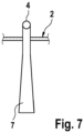
- Fig.7 shows an inflow line 7 of the device for draining waste water, in particular dialysis fluid.
- the inflow line 7 is designed as a diffuser and has a cross-section that increases towards the end, so that the waste water is slowed down and enters the free-fall section at a lower speed, for example at 1 m/s or less. This at least reduces or prevents unwanted splashing.
Landscapes
- Health & Medical Sciences (AREA)
- Heart & Thoracic Surgery (AREA)
- Urology & Nephrology (AREA)
- Public Health (AREA)
- Animal Behavior & Ethology (AREA)
- Engineering & Computer Science (AREA)
- Anesthesiology (AREA)
- Biomedical Technology (AREA)
- Hematology (AREA)
- Life Sciences & Earth Sciences (AREA)
- Veterinary Medicine (AREA)
- General Health & Medical Sciences (AREA)
- Emergency Medicine (AREA)
- Vascular Medicine (AREA)
- Pulmonology (AREA)
- External Artificial Organs (AREA)
- Electrical Discharge Machining, Electrochemical Machining, And Combined Machining (AREA)
- Cyclones (AREA)
Description
- Die Erfindung betrifft eine Vorrichtung zum Ableiten von Abwasser, insbesondere von gebrauchter oder verbrauchter Dialysierflüssigkeit, die eine Mehrzahl von Leitungsanschlüssen zum Anschluss von Abwasserleitungen, insbesondere Abwasserleitungen von Dialysegeräten, aufweist.
- Der Einsatz von medizintechnischen Geräten in der Klinik setzt vielfach die Ableitung von gebrauchten oder verbrauchten Flüssigkeiten in einen Ablauf voraus. Diese Flüssigkeiten werden nachfolgend als Abwasser bezeichnet.
- Die bekannten Dialysegeräte beispielsweise verfügen über Abwasserschläuche, um gebrauchte bzw. verbrauchte Dialysierflüssigkeit abzuleiten. Beim Ableiten der Dialysierflüssigkeit ist zu beachten, dass der Abwasserschlauch mit dem Abwasserleitungssystem nicht in direkter Flüssigkeitsverbindung stehen darf, da ansonsten die Gefahr einer Kontamination besteht. Dies kann dadurch erreicht werden, dass das freie Ende des Abwasserschlauchs nicht direkt an ein Abwasserleitungssystem angeschlossen wird, sondern eine definierte Freifallstrecke eingehalten wird. Das freie Ende des Abwasserschlauchs kann beispielsweise in einer definierten Höhe über dem Boden eines Abflussbeckens (Waschbeckens) angeordnet werden.
- In der Praxis stellt sich das Problem einer ausreichenden Führung und Fixierung der Abwasserleitung unter gleichzeitiger Einhaltung einer definierten Freifallstrecke. Dieses Problem stellt sich sowohl in der chronischen als auch der Akutdialyse. Insbesondere erweist sich die Führung und Fixierung mehrerer Abwasserleitungen beim Einsatz von mehreren Dialysegeräten auf einer Station als problematisch.
- Im Bereich der Haushalts- oder Sanitärtechnik ist das Prinzip der Bildung einer Freifallstrecke aus der
US 7 290 557 B1 bekannt. Allerdings stellt sich in der Haushalts- oder Sanitärtechnik nicht das Problem der Kontamination medizinischer Flüssigkeiten oder medizintechnischer Einrichtungen. DieUS 7 290 557 B1 beschreibt ein Anschlussstück für den Anschluss eines Brauchwasserschlauchs einer Spülmaschine an das Fallrohr eines Brauchwasserleitungssystems. Das Anschlussstück, das mittels einer Schraub- oder Steckverbindung mit einem Fallrohr fest verbunden wird, weist ein Rohrstück auf, durch das das Brauchwasser in das Fallrohr strömt. Zu besseren Be- bzw. Entlüftung weist dieses Rohrstück eine seitliche Öffnung auf. Anschlussstück und Fallrohr haben im Wesentlichen den gleichen Durchmesser. Das Anschlussstück besteht vorzugsweise aus Kunststoff. - Nachteilig ist, dass das Anschlussstück nur den Anschluss eines einzigen Brauchwasserschlauchs an ein Fallrohr erlaubt. Für den Anschluss von mehreren Brauchwasserschläuchen sind mehrere Anschlusstücke erforderlich, wobei an dem Fallrohr entsprechende Verzweigungen erforderlich sind, an denen die Anschlusstücke angeschlossen werden können. Dies erfordert einen erhöhten Platzbedarf.
- Darüber hinaus ist im Bereich der Haushaltstechnik die Fixierung einer Brauchwasserleitung, beispielsweise des Brauchwasserschlauchs einer Waschmaschine, an dem Beckenrand eines Waschbeckens bekannt.
- Die
EP 2 286 850 A1 beschreibt eine Vorrichtung zum Ableiten von Abwasser für Dialysegeräte, welche eine Mehrzahl von Leitungsanschlüssen zum Anschluss von Abwasserleitungen des Dialysegeräts aufweist. Die Vorrichtung zum Ableiten von Abwasser ist als ein Behälter ausgebildet, der zur Montage an einem Wandbefestigungsteil ausgebildet ist. Der Behälter weist einen trichterförmigen Teil auf, der von einem Deckelteil verschlossen wird. An dem Deckelteil sind die Leitungsanschlüsse für die Abwasserleitungen des Dialysegeräts vorgesehen. Die Leitungsanschlüsse bilden eine Freifallstrecke für das Abwasser vom Deckelteil bis zu der schrägen Wand des trichterförmigen Teils des Behälters. - Die
US 4 176 684 A befasst sich allgemein mit dem Ableiten von Abwasser in der Haushaltstechnik, insbesondere mit dem Ableiten von Abwasser einer Waschmaschine oder eines Geschirrspülers in ein Spülbecken, wobei die Aufgabe derUS 4 176 684 A allein in dem Spritzschutz liegt. Die Vorrichtung ist als ein trichterförmiger Teil ausgebildet, welcher auf den Boden des Spülbeckens aufgestellt werden soll. Der trichterförmige Teil verfügt über einen in der Höhe einstellbaren Anschlussteil, der in den Zulauf des trichterförmigen Teils geschraubt ist. Der Anschlussteil erlaubt eine Verbindung mit einer konventionellen Armatur einer Waschmaschine oder eines Geschirrspülers, welche Leitungsanschlüsse zum Zuführen von Frischwasser und Ableiten von Abwasser umfasst. - Der Erfindung liegt die Aufgabe zugrunde, die Ableitung von Abwasser, insbesondere von gebrauchter oder verbrauchter Dialysierflüssigkeit, zu vereinfachen, ohne dass die Gefahr einer Kontamination besteht.
- Die Lösung dieser Aufgabe erfolgt erfindungsgemäß mit den Merkmalen des Patentanspruchs 1. Die abhängigen Ansprüche betreffen bevorzugte Ausführungsformen der Erfindung.
- Die erfindungsgemäße Vorrichtung zum Ableiten von Abwasser ist insbesondere für medizinische Geräte, insbesondere Dialysegeräte, bestimmt, um medizinische Flüssigkeiten ableiten zu können. Die bevorzugte Verwendung liegt also nicht in der Versorgungstechnik (Haus- oder Gebäudetechnik) mit technischen Installationen für die Abwasserentsorgung. Die erfindungsgemäße Vorrichtung zum Ableiten von Abwasser, insbesondere von gebrauchter oder verbrauchter Dialysierflüssigkeit, verfügt über eine Mehrzahl von Leitungsanschlüssen zum Anschluss von Abwasserleitungen, insbesondere Abwasserleitungen von Dialysegeräten. Die Vorrichtung kann beispielsweise zwei oder drei oder mehr als drei Leitungsanschlüsse aufweisen, so dass die Abwasserleitungen einer Mehrzahl von Geräten, insbesondere Dialysegeräten, angeschlossen werden können.
- Das Grundprinzip der Erfindung liegt darin, dass die erfindungsgemäße Vorrichtung zum Ableiten von Abwasser als ein auf den Boden eines Beckens aufstellbares Teil ausgebildet ist. Die Vorrichtung bildet daher einen einfach zu handhabenden Standfuß, der sich auf den Boden eines Beckens aufstellen lässt. Die Vorrichtung erlaubt den Anschluss mehrerer Abwasserleitungen und erfordert dabei nur einen geringen Platzbedarf. Sie kann auch seitliche Zugkräfte der Anschlussleitungen aufnehmen.
- Eine ausreichende Standfestigkeit kann allein aufgrund des Gewichts (Schwerkraft) der Vorrichtung erreicht werden, ohne dass eine Befestigung der Vorrichtung beispielsweise am Rand eines Beckens erforderlich wäre. Daher kann die Vorrichtung ohne eine weitere Fixierung auch in der Mitte des Beckens platziert werden.
- Eine Kontamination wird dadurch wirkungsvoll verhindert, dass die Leitungsanschlüsse mit mindestens einer Zustromleitung in Fluidverbindung stehen, deren unteres Ende unter Bildung einer Freifallstrecke im Abstand zu der Unterseite bzw. Standfläche des auf den Boden des Beckens aufstellbaren Teils angeordnet ist. Die Länge der Freifallstrecke wird durch die Höhe des unteren Endes der Zustromleitung bzw. der Abmessungen der Vorrichtung bestimmt. Aufgrund der Freifallstrecke kann das Abwasser auch unter relativ hohem Druck, der beispielsweise zwischen 2 und 4 bar liegen kann, ohne die Gefahr einer Kontamination abgeleitet werden.
- Die Vorrichtung zum Ableiten von Abwasser weist ein Mantelteil auf, das die mindestens eine Zustromleitung umschließt. Das Mantelteil bildet einen Spritzschutz in Form einer Haube, so dass das unter relativ hohem Druck aus der Zustromleitung austretende Abwasser nicht in die Umgebung gelangen kann. Allein aufgrund des Gewichts des Mantelteils kann eine ausreichende Standfestigkeit erreicht werden.
- Der Mantelteil weist vorzugsweise eine Mehrzahl von seitlich abstehenden Standbeinen auf, mit denen sich die Vorrichtung seitlich am Boden des Beckens sicher abstützen kann, so dass die Vorrichtung selbst dann nicht kippen oder umfallen kann, wenn allein das Eigengewicht für eine ausreichende Standfestigkeit nicht ausreichen sollte. Die Aufstandsfläche ist somit ein Vielfaches größer als der Durchmesser der Abwasserleitungen. Zusätzliche Standbeine brauchen aber nicht vorgesehen zu sein.
- Eine besonders bevorzugte Ausführungsform sieht vor, dass die Standbeine Standfüße aufweisen, so dass die Unterseite des Mantelteils im Abstand zum Boden des Beckens angeordnet ist. Diese Ausführungsform hat den Vorteil, dass eine Freifallstrecke auch für an der Wandung des Mantelteils abfließendes Spritzwasser geschaffen wird. Die Länge der Freifallstrecke, d. h. des Abstandes zwischen der unteren Kante des Mantelteils und dem Boden wird durch die Abmessungen der Standfüße. bestimmt. Die Standfüße ermöglichen einen freier Abfluss von Abwasser unter dem Mantelteil zu allen Seiten.
- Bei einer weiteren Ausführungsform weist die Vorrichtung ein Deckelteil auf, an dem die Leitungsanschlüsse vorgesehen sind. Der Deckelteil und der Mantelteil können zwei fest miteinander verbundene Teile oder einstückig gefertigt sein. Der Deckelteil ist vorzugsweise ein kreisförmiger oder tellerförmiger Teil, während der Mantelteil vorzugsweise ein hohlzylindrischer Teil ist. Deckelteil und Mantelteil können aber auch andere Formen haben. Beispielsweise kann der Deckelteil halbkugelförmig und der Mantelteil zylindrisch sein.
- Die mindestens eine Zustromleitung kann unterschiedlich ausgebildet und angeordnet sein, beispielsweise kann die mindestens eine Zustromleitung ein Röhrchen sein. Das Röhrchen ist vorzugsweise ein gerades Röhrchen, kann aber auch gebogen sein. Das Röhrchen braucht nicht senkrecht angeordnet zu sein, sondern kann auch schräg angeordnet sein.
- Das obere Ende der Zustromleitung ist vorzugsweise als Anschlussstutzen zum Anschluss einer Schlauchleitung ausgebildet. Der Anschlussstutzen ist vorzugsweise abgewinkelt, so dass die Abflussleitung von der Seite herangeführt und seitlich angeschlossen werden kann.
- Eine bevorzugte Ausführungsform sieht vor, dass ein Leitungsanschluss jeweils mit einer Zustromleitung in Flüssigkeitsverbindung steht. Es ist aber auch möglich, dass sämtliche Leitungsanschlüsse mit nur einer Zustromleitung in Flüssigkeitsverbindung stehen. Einzelne Leitungsanschlüsse können auch mit mehreren Zustromleitungen in Flüssigkeitsverbindung stehen.
- Die Zustromleitungen können die gleiche Länge haben, so dass sie den gleichen Abstand zu der Unterseite des auf den Boden des Beckens aufstellbaren Teils haben oder die Zustromleitungen können unterschiedliche Längen haben, so dass sie unterschiedliche Abstände zu der Unterseite des auf den Boden des Beckens aufstellbaren Teils haben. Die Zustromleitungen können den gleichen Durchmesser oder unterschiedliche Durchmesser haben. Die Länge und die Durchmesser der Zustromleitungen können somit an unterschiedliche Flussraten oder unterschiedliche Drücke der einzelnen Geräte individuell angepasst werden.
- Der Deckelteil und/oder der Mantelteil bestehen vorzugsweise aus rostfreiem Stahl (Edelstahl), der leicht zu reinigen bzw. desinfizieren ist. Wenn Deckelteil und/oder Mantelteil aus Edelstahl bestehen, hat die Vorrichtung auch ein ausreichendes Eigengewicht, so dass eine ausreichende Standfestigkeit gegeben ist. Die beiden Edelstahlteile können einfach miteinander verbunden, beispielsweise verschweißt, aber auch verklebt werden. Folglich ist es nicht erforderlich, den Spritzschutz aus einem Teil zu fertigen. Wenn die Standbeine eine ausreichende Standfestigkeit sicherstellen, können Deckelteil und/oder Mantelteil grundsätzlich aber auch aus Kunststoff bestehen.
- In der Praxis liegen bei bestimmten Anwendungen relative hohe Flüsse vor, so dass das Abwasser, insbesondere die Dialysierflüssigkeit mit hoher Strömungsgeschwindigkeit, beispielsweise 6 m/s, aus der Zustromleitung in die Freifallstrecke eintritt, wodurch es zu unerwünschtem Spritzen kommen kann.
- Eine weitere Ausführungsform sieht vor, dass die Zustromleitung oder mindestens eine der Zustromleitungen einen Diffusor aufweist oder als Diffusor ausgebildet ist, so dass die Flüssigkeitsströmung verlangsamt wird. Anstelle der Zustromleitung kann auch der zugehörige Leitungsanschluss einen Diffusor aufweisen oder als Diffusor ausgebildet sein. Bei einer bevorzugten Ausführungsform weist die Zustromleitung oder mindestens eine der Zustromleitungen einen zum unteren Ende aufweitenden Querschnitt auf. Der Querschnitt kann sich über die gesamte Länge oder nur über einen Teil der Länge, beispielsweise auch nur am unteren Endstück der Zustromleitung vergrößern. Aufgrund der geringeren Strömungsgeschwindigkeit des Abwassers, insbesondere der Dialysierflüssigkeit, wird unerwünschtes Spritzen zumindest vermindert oder verringert.
- Nachfolgend werden Ausführungsbeispiele der erfindungsgemäßen Vorrichtung zum Ableiten von Abwasser unter Bezugnahme auf die Figuren im Einzelnen beschrieben.
- Es zeigen:
- Fig. 1
- ein Ausführungsbeispiel der erfindungsgemäßen Vorrichtung in perspektivischer Darstellung,
- Fig. 2
- die Vorrichtung von
Fig. 1 in der Draufsicht, - Fig. 3
- einen Schnitt durch die Vorrichtung von
Fig. 1 , - Fig. 4
- ein zweites Ausführungsbeispiel der Vorrichtung in geschnittener Darstellung,
- Fig. 5
- ein drittes Ausführungsbeispiel der Vorrichtung in geschnittener Darstellung,
- Fig. 6
- eine perspektivische Darstellung der Vorrichtung, wobei die Abwasserschläuche an die Vorrichtung angeschlossen sind, und
- Fig. 7
- ein weiteres Ausführungsbeispiel einer Zustromleitung.
-
Fig. 1 zeigt eine perspektivische Darstellung der erfindungsgemäßen Vorrichtung zum Ableiten von Abwasser.Fig. 2 zeigt die Vorrichtung in der Draufsicht. Die Vorrichtung weist einen hohlzylindrischen Mantelteil 1 auf, der an der Oberseite von einem kreisförmigen Deckelteil 2 verschlossen ist. Mantelteil 1 und Deckelteil 2 bestehen aus rostfreiem Edelstahl und sind zu einem haubenförmigen Körper, der auch als Glocke bezeichnet werden kann, miteinander verbunden, insbesondere verschweißt. - An dem Deckelteil 2 sind drei im Abstand zueinander angeordnete Leitungsanschlüsse 3, 4, 5 zum Anschluss von nicht dargestellten Schlauchleitungen vorgesehen. Die Leitungsanschlüsse 3, 4, 5 sind als Anschlussstutzen ausgebildet, auf die sich Abwasserschläuche von medizintechnischen Geräten, insbesondere Dialysegeräten, passend aufschieben lassen. Anstelle der Anschlussstutzen können aber auch Schlauchleitungskupplungen oder dergleichen vorgesehen sein, um die Schlauchleitungen einfach anschließen bzw. abnehmen zu können. Die Anschlussstutzen 3, 4, 5 sind gegenüber der Achse des zylindrischen Mantelteils 1 um 90° abgewinkelt, so dass sich die Abwasserschläuche seitlich aufschieben lassen. Der mittlere Anschlussstutzen 3 hat einen Außendurchmesser d1, der größer ist als die Außendurchmesser d2, d3 der äußeren Anschlussstutzen 4, 5, so dass auf den mittleren Anschlussstutzen 3 eine Abwasserschlauch mit einem größeren Durchmesser passend aufgeschoben werden kann. Die Anschlussstutzen sind mit Zustromleitungen 6, 7, 8 einstückig, die sich in das Innere des Mantelteils 1 erstrecken. Die Zustromleitungen 6, 7, 8 mit den Anschlussstutzen 3, 4, 5 bestehen vorzugsweise aus Edelstahl (
Fig. 3 ). -
Fig. 3 zeigt einen Schnitt durch den Mantelteil 1. Die Zustromleitungen 6, 7, 8 sind gerade Röhrchen, die sich von dem Deckelteil 2 nach unten erstrecken. Die mittlere Zustromleitung 6 erstreckt sich auf der Längsachse und die beiden äußeren Zustromleitungen 7, 8 neben der Längsachse des zylindrischen Mantelteils 1. Die Zustromleitungen 6, 7, 8 haben die gleiche Länge 1. Die unteren Enden der Zustromleitungen 6, 7, 8 sind im Abstand zu der unteren Kante des Mantelteils 1 angeordnet, so dass für das aus den Zustromleitungen 6, 7, 8 austretende Abwasser eine Freifallstrecke ausgebildet wird. Dieser Abstand ist inFig. 3 mit dem Bezugszeichen A bezeichnet. - Der Mantelteil 1 weist eine Mehrzahl von Standbeinen 9 auf. Bei dem vorliegenden Ausführungsbeispiel sind drei Standbeine 9 vorgesehen (Dreibein), die sich von dem unteren Rand des Mantelteils 1 radial nach Außen erstrecken. Die Standbeine 9 weisen jeweils einen Standfuß 10 auf. Die Standfüße 10 können an den Standbeinen 9 befestigte, beispielsweise mit den Standbeinen verschraubte Gummifüße sein, mit denen die Vorrichtung sicher auf dem Boden aufsteht und nicht verrutschen oder kippen kann. Da die Vorrichtung mit den Standfüßen 10 auf dem Boden aufsteht, ist die Unterkante des Mantelteils 1 im Abstand zum Boden 11 angeordnet. Dieser Abstand ist in
Fig. 3 mit dem Bezugszeichen B bezeichnet. - Die Vorrichtung zum Ableiten von Abwasser wird auf den Boden 11 eines Abwasserbeckens, beispielsweise eines Waschbeckens gestellt. Während des Betriebs der Vorrichtung tritt das Abwasser unter einem relativ hohen Druck, der bei 3 bar liegen kann, aus den Zustromleitungen 6, 7, 8 aus und spritzt auf den Boden 11 des Beckens. Aufgrund der Freifallstrecke, die eine Länge L = A + B hat, wird eine Rückkontamination vermieden. Das Abwasser kann unter dem Mantelteil 1 zu allen Seiten in das Becken abfließen und in den Abfluss des Beckens ablaufen. Spritzwasser wird von dem Deckel- und Mantelteil 1, 2 zurückgehalten und fließt an der Wandung des Mantelteils 1 ab. Eine Rückkontamination des abfließenden Spritzwassers wird dadurch vermieden, dass die Unterkante des Mantelteils 1 im Abstand zu dem Beckenboden 11 angeordnet ist, wodurch eine Freifallstrecke mit der Länge L = B ausgebildet wird. Das Spritzwasser kann an der Unterkante des Mantelteils 1 über dessen gesamten Umfang abfließen oder abtropfen und unter dem Mantelteil in den Abfluss ablaufen.
-
Fig. 4 zeigt ein zweites Ausführungsbeispiel der Vorrichtung in geschnittener Darstellung, das sich von der ersten Ausführungsform dadurch unterscheidet, dass die Zustromleitungen 6, 7, 8 unterschiedliche Längen l1, l2 haben. Die einander entsprechenden Teile sind mit den gleichen Bezugszeichen versehen. Die mittlere Zustromleitung 6 hat eine größere Länge l1 als die äußeren Zustromleitungen. Folglich ergeben sich Freifallstrecken unterschiedlicher Längen L1, L2. -
Fig. 5 zeigt ein drittes Ausführungsbeispiel der Vorrichtung in geschnittener Darstellung, das sich von der ersten Ausführungsform dadurch unterscheidet, dass die Zustromleitungen 6, 7, 8 den gleichen Durchmesser d und die gleiche Länge 1 haben. Die einander entsprechenden Teile sind mit den gleichen Bezugszeichen versehen. -
Fig. 6 zeigt eine perspektivische Darstellung der Vorrichtung zum Ableiten von Brauchwasser, wobei die Abwasserschläuche 12, 13, 14 eines nicht dargestellten medizintechnischen Geräts an den Anschlussstutzen 3, 4, 5 angeschlossen sind. Der mittlere Abwasserschlauch 12 hat einen größeren Schlauchdurchmesser als die äußeren Abwasserschläuche 13, 14. Die seitlich an die Anschlussstutzen 3, 4, 5 angeschlossenen Abwasserschläuche 12, 13, 14 sind in einem halbkreisförmigen Bogen über den Deckelteil 2 zurückgeführt und mit einem Klettband 15 oder dergleichen zu einem Schlauchbündel zusammengebunden. Die Vorrichtung dient somit auch der Führung und Fixierung der Abwasserschläuche 12, 13, 14. Die Abwasserschläuche 12, 13, 14 können sich aber auch zu der anderen Seite erstrecken, ohne einen halbkreisförmigen Bogen zu bilden. - Mit der erfindungsgemäßen "Abfluss-Glocke" kann für mehrere medizintechnische Geräte gleichzeitig ein sicherer, stabiler Abfluss hergestellt werden. Die Abfluss-Glocke kann in jedem Waschbecken platziert werden. Die Führung und Fixierung der Abwasserschläuche stellt einen kontrollierten Ablauf des Abwassers sicher, wobei die Freifallstrecken eine Rückkontamination in den jeweiligen Abwasserschlauch verhindern. Als Schweißteil kann die Abfluss-Glocke aufgrund der einfachen geometrischen Form ohne hohe Anforderungen an die Fertigungstechnik, insbesondere die Maßhaltigkeit, kostengünstig hergestellt werden. Die Abfluss-Glocke ist ohne Werkzeuge frei zugänglich und lässt sich einfach reinigen bzw. desinfizieren. Da das Abwasser zu allen Seiten nach unten abfließen kann, ist das Abwasser im Becken gut sichtbar, so dass dessen optische Beschaffenheit überwacht werden kann. Die Abfluss-Glocke ist nicht nur in der Medizintechnik, sondern in sämtlichen Bereichen universell einsetzbar, wenn Flüssigkeiten in einen Ablauf abgeleitet werden sollen.
-
Fig. 7 zeigt eine Zustromleitung 7 der Vorrichtung zum Ableiten von Abwassser, insbesondere Dialysierflüssigkeit. Die Zustromleitung 7 ist als Diffusor ausgebildet und weist einen zum Ende hin sich vergrößernden Querschnitt auf, so dass das Abwasser abgebremst wird und mit einer geringeren Geschwindigkeit in die Freifallstrecke eintritt, beispielsweise mit 1 m/s oder weniger. Dadurch wird unerwünschtes Spritzen zumindest vermindert oder verhindert.
Claims (16)
- Vorrichtung zum Ableiten von Abwasser eines medizintechnischen Gerätes, welche eine Mehrzahl von Leitungsanschlüssen (3, 4, 5) zum Anschluss von Abwasserleitungen des medizintechnischen Gerätes aufweist, dadurch gekennzeichnet, dass die Vorrichtung zum Ableiten von Abwasser als ein auf den Boden eines Beckens aufstellbares Teil ausgebildet ist, wobei die Leitungsanschlüsse (3, 4, 5) mit mindestens einer Zustromleitung (6, 7, 8) in Flüssigkeitsverbindung stehen, deren unteres Ende unter Bildung einer Freifallstrecke im Abstand zu der Unterseite des auf den Boden des Beckens aufstellbaren Teils angeordnet ist, wobei die Vorrichtung zum Ableiten von Abwasser ein Mantelteil (1) aufweist, das die mindestens eine sich in das Innere des Mantelteils (1) erstreckende Zustromleitung (6, 7, 8) umschließt.
- Vorrichtung zum Ableiten von Abwasser nach Anspruch 1, dadurch gekennzeichnet, dass das Mantelteil (1) eine Mehrzahl von seitlich abstehenden Standbeinen (9) aufweist.
- Vorrichtung zum Ableiten von Abwasser nach Anspruch 2, dadurch gekennzeichnet, dass die Standbeine (9) Standfüße (10) aufweisen, so dass die Unterseite des Mantelteils (1) im Abstand zum Boden des Beckens angeordnet ist.
- Vorrichtung zum Ableiten von Abwasser nach Anspruch 2 oder 3, dadurch gekennzeichnet, dass der Mantelteil (1) ein hohlzylindrischer Teil ist.
- Vorrichtung zum Ableiten von Abwasser nach einem der Ansprüche 1 bis 4, dadurch gekennzeichnet, dass die Vorrichtung zum Ableiten von Abwasser ein Deckelteil (1) aufweist, an dem die Leitungsanschlüsse (3, 4, 5) vorgesehen sind.
- Vorrichtung zum Ableiten von Abwasser nach Anspruch 5, dadurch gekennzeichnet, dass der Deckelteil (1) ein kreisförmiger Teil ist.
- Vorrichtung zum Ableiten von Abwasser nach einem der Ansprüche 1 bis 6,
dadurch gekennzeichnet, dass die mindestens eine Zustromleitung (6, 7, 8) ein Röhrchen ist, dessen oberes Ende als Anschlussstutzen (3, 4, 5) zum Anschluss einer Schlauchleitung ausgebildet ist. - Vorrichtung zum Ableiten von Abwasser nach Anspruch 7, dadurch gekennzeichnet, dass der Anschlussstutzen (3, 4, 5) abgewinkelt ist.
- Vorrichtung zum Ableiten von Abwasser nach einem der Ansprüche 1 bis 8,
dadurch gekennzeichnet, dass ein Leitungsanschluss (3, 4, 5) jeweils mit einer Zustromleitung in Fluidverbindung steht. - Vorrichtung zum Ableiten von Abwasser nach Anspruch 9, dadurch
gekennzeichnet, dass die Zustromleitungen (6, 7, 8) die gleiche Länge haben, so dass die unteren Enden der Zustromleitungen (6, 7, 8) den gleichen Abstand zu der Unterseite des auf den Boden des Beckens aufstellbaren Teils haben. - Vorrichtung zum Ableiten von Abwasser nach Anspruch 9, dadurch
gekennzeichnet, dass die Zustromleitungen (6, 7, 8) unterschiedliche Längen haben, so dass die die unteren Enden der Zustromleitungen (6, 7, 8) unterschiedliche Abstände zu der Unterseite des auf den Boden des Beckens aufstellbaren Teils haben. - Vorrichtung zum Ableiten von Abwasser nach einem der Ansprüche 9 bis 11, dadurch gekennzeichnet, dass die Zustromleitungen (6, 7, 8) den gleichen Durchmesser haben.
- Vorrichtung zum Ableiten von Abwasser nach einem der Ansprüche 9 bis 11, dadurch gekennzeichnet, dass die Zustromleitungen (6, 7, 8) unterschiedliche Durchmesser haben.
- Vorrichtung zum Ableiten von Abwasser nach einem der Ansprüche 1 bis 13, dadurch gekennzeichnet, dass der Mantelteil (1) und/oder der Deckelteil (2) aus Edelstahl bestehen.
- Vorrichtung zum Ableiten von Abwasser nach einem der Ansprüche 1 bis 14,
dadurch gekennzeichnet, dass die Zustromleitung (6, 7, 8) oder mindestens eine der Zustromleitungen (6, 7, 8) einen Diffusor aufweist oder als Diffusor ausgebildet ist, so dass die Flüssigkeitsströmung verlangsamt wird. - Vorrichtung zum Ableiten von Abwassser nach Anspruch 15, dadurch
gekennzeichnet, dass die Zustromleitung (6, 7, 8) oder eine der Zustromleitungen (6, 7, 8) einen sich zum unteren Ende aufweitenden Querschnitt aufweist.
Applications Claiming Priority (2)
| Application Number | Priority Date | Filing Date | Title |
|---|---|---|---|
| DE102018000146.7A DE102018000146A1 (de) | 2018-01-11 | 2018-01-11 | Vorrichtung zum Ableiten von Abwasser |
| PCT/EP2019/050281 WO2019137885A1 (de) | 2018-01-11 | 2019-01-08 | Vorrichtung zum ableiten von abwasser |
Publications (2)
| Publication Number | Publication Date |
|---|---|
| EP3737441A1 EP3737441A1 (de) | 2020-11-18 |
| EP3737441B1 true EP3737441B1 (de) | 2024-06-19 |
Family
ID=65013686
Family Applications (1)
| Application Number | Title | Priority Date | Filing Date |
|---|---|---|---|
| EP19700345.2A Active EP3737441B1 (de) | 2018-01-11 | 2019-01-08 | Vorrichtung zum ableiten von abwasser |
Country Status (9)
| Country | Link |
|---|---|
| US (1) | US12029840B2 (de) |
| EP (1) | EP3737441B1 (de) |
| JP (1) | JP7451408B2 (de) |
| KR (1) | KR102717100B1 (de) |
| CN (1) | CN111565773A (de) |
| BR (1) | BR112020013835A2 (de) |
| DE (1) | DE102018000146A1 (de) |
| TW (1) | TWI788503B (de) |
| WO (1) | WO2019137885A1 (de) |
Families Citing this family (2)
| Publication number | Priority date | Publication date | Assignee | Title |
|---|---|---|---|---|
| US20240299727A1 (en) * | 2021-02-04 | 2024-09-12 | Nipro Corporation | Extracorporeal circulation circuit |
| WO2025157780A1 (en) * | 2024-01-23 | 2025-07-31 | Gambro Lundia Ab | Handling waste fluid generated during dialysis therapy |
Citations (1)
| Publication number | Priority date | Publication date | Assignee | Title |
|---|---|---|---|---|
| US4176684A (en) * | 1977-10-26 | 1979-12-04 | Kelso Eileen E | Splash down |
Family Cites Families (25)
| Publication number | Priority date | Publication date | Assignee | Title |
|---|---|---|---|---|
| US3515280A (en) * | 1968-12-03 | 1970-06-02 | Watson H Parker | Stacked element filter apparatus |
| US3752318A (en) * | 1971-12-06 | 1973-08-14 | Texaco Inc | Liquid separation apparatus |
| US4449969A (en) * | 1982-02-03 | 1984-05-22 | The Kendall Company | Drainage receptacle with support frame |
| US4431534A (en) * | 1982-07-23 | 1984-02-14 | Exxon Production Research Co. | Liquid-liquid separation apparatus |
| US4824562A (en) * | 1987-03-12 | 1989-04-25 | R. E. Wright Associates, Inc. | In well separator for heavier liquid |
| US4955873A (en) * | 1988-05-06 | 1990-09-11 | Pfizer Hospital Products Group, Inc. | Stabilizing support stand |
| US5217038A (en) * | 1992-03-31 | 1993-06-08 | Pppk, Inc. | Apparatus for emptying a hazardous waste container |
| US5309670A (en) * | 1992-10-27 | 1994-05-10 | Bates Charles L | Plant stand |
| TW264383B (de) * | 1992-12-14 | 1995-12-01 | Terumo Corp | |
| US6358232B1 (en) * | 1994-12-29 | 2002-03-19 | Bemis Manufacturing Company | Method and apparatus for removing and disposing of body fluids |
| US6210381B1 (en) * | 1999-10-08 | 2001-04-03 | Jeffrey W. Morse | Splash-shield and related fluid delivery device |
| US6267901B1 (en) * | 2000-01-31 | 2001-07-31 | Albert Franklin | Methods and apparatus for wastewater treatment on offshore structures |
| JP2004503302A (ja) * | 2000-06-09 | 2004-02-05 | アボット・ラボラトリーズ | 可撓性容器から流体を移動させるアセンブリ |
| US6581627B2 (en) * | 2000-06-30 | 2003-06-24 | Jack R. Dillon | Dialysis wall station |
| US6926239B1 (en) * | 2004-01-23 | 2005-08-09 | Dimaggio Edward J. | Mounting assembly for a waste discharge line of a medical treatment apparatus |
| US7481243B2 (en) * | 2004-02-19 | 2009-01-27 | Allegiance Corporation | Method and apparatus for the disposal of waste fluids |
| US7290557B1 (en) | 2005-01-12 | 2007-11-06 | Bowman Dennis E | Drain line adapter air gap fitting |
| US8025173B2 (en) * | 2006-09-07 | 2011-09-27 | Allegiance Corporation | Collapsible canister liner for medical fluid collection |
| DE102009038571B4 (de) * | 2009-08-22 | 2011-07-14 | Völker, Manfred, 63825 | Versorgungseinrichtung für Dialysegeräte |
| EP2465557A1 (de) * | 2010-12-17 | 2012-06-20 | Weibel CDS AG | Vorrichtung für die Abgabe einer Flüssigkeit aus einem Behälter |
| US8845605B2 (en) * | 2011-05-08 | 2014-09-30 | H & M Innovations, Llc | Collection and filtration via suction of biological material during surgical procedure |
| US20150119823A1 (en) * | 2013-10-28 | 2015-04-30 | Patrick V. Marasco | Wound treatment and containment arrangement |
| JP2016106801A (ja) | 2014-12-05 | 2016-06-20 | ブルークロス株式会社 | 体液を含む廃液の処理方法およびその処理装置並びに体液を含む廃液の貯留容器 |
| US10513842B2 (en) * | 2017-07-31 | 2019-12-24 | Gene Quesada | Portable dialysis drainage system and method |
| US20190106872A1 (en) * | 2017-10-06 | 2019-04-11 | As Ip Holdco, Llc | Medical toilet |
-
2018
- 2018-01-11 DE DE102018000146.7A patent/DE102018000146A1/de not_active Ceased
-
2019
- 2019-01-08 KR KR1020207022593A patent/KR102717100B1/ko active Active
- 2019-01-08 WO PCT/EP2019/050281 patent/WO2019137885A1/de not_active Ceased
- 2019-01-08 BR BR112020013835-5A patent/BR112020013835A2/pt not_active IP Right Cessation
- 2019-01-08 US US16/960,324 patent/US12029840B2/en active Active
- 2019-01-08 EP EP19700345.2A patent/EP3737441B1/de active Active
- 2019-01-08 CN CN201980007929.8A patent/CN111565773A/zh active Pending
- 2019-01-08 JP JP2020538625A patent/JP7451408B2/ja active Active
- 2019-01-08 TW TW108100698A patent/TWI788503B/zh active
Patent Citations (1)
| Publication number | Priority date | Publication date | Assignee | Title |
|---|---|---|---|---|
| US4176684A (en) * | 1977-10-26 | 1979-12-04 | Kelso Eileen E | Splash down |
Also Published As
| Publication number | Publication date |
|---|---|
| CN111565773A (zh) | 2020-08-21 |
| JP7451408B2 (ja) | 2024-03-18 |
| US20200368419A1 (en) | 2020-11-26 |
| WO2019137885A1 (de) | 2019-07-18 |
| US12029840B2 (en) | 2024-07-09 |
| TWI788503B (zh) | 2023-01-01 |
| KR102717100B1 (ko) | 2024-10-15 |
| DE102018000146A1 (de) | 2019-07-11 |
| BR112020013835A2 (pt) | 2020-12-01 |
| EP3737441A1 (de) | 2020-11-18 |
| KR20200109328A (ko) | 2020-09-22 |
| JP2021510336A (ja) | 2021-04-22 |
| TW201930689A (zh) | 2019-08-01 |
Similar Documents
| Publication | Publication Date | Title |
|---|---|---|
| EP3495576B1 (de) | System aus einem geruchsverschluss und einem aufnahmekörper sowie ein geruchsverschluss | |
| EP3737441B1 (de) | Vorrichtung zum ableiten von abwasser | |
| DE60200339T2 (de) | Ablaufrinne und Nachspülungssystem für Melkstände | |
| DE69922947T2 (de) | Wassereinlauf für Badewanne in Form einer Kaskade | |
| DE10360310A1 (de) | Ablaufvorrichtung | |
| DE19528160C2 (de) | Rohr- und Schlauchinstallation an und in Mediensäulen für die Behandlung von Körperflüssigkeiten, insbesondere für ein Dialysegerät | |
| EP0499914A2 (de) | Wasserzapfarmatur mit Rücksaugsicherung | |
| EP0660019B1 (de) | Verfahren zur Befestigung eines mit weingstens zwei Befestigungslöchern versehenen Rohrleitungs-Formstückes aus Kunststoff an gelochten Blechträgern | |
| DE10319587B3 (de) | Vorrichtung zur Wärmebehandlung von Nahrungsmitteln | |
| EP1775395A1 (de) | Ablaufarmatur für sanitäre Anlagen | |
| DE3917015C2 (de) | Sicherheitsschlauch mit einem Druckschlauch, einem Hüllschlauch und mit einer Anschlußarmatur | |
| EP0105303A1 (de) | Bewässerungsgerät für pflanzen | |
| EP2381041B1 (de) | Zu- und Überlaufarmatur für Badewannen | |
| DE8906228U1 (de) | Einbaugeruchsverschluß | |
| DE102024138081B3 (de) | Zulaufeinheit und Sicherungsarmatur für einen offenen Tank und Gerät zum Anschluss an das Trinkwassernetz | |
| DE3409457A1 (de) | Schutzvorrichtung zur vermeidung einer verkeimung in fluessigkeiten | |
| EP2060855A1 (de) | Anschlussstück für ein schlauchförmiges Innenzirkulationsrohr, Wasserzirkulationsleitung mit einem solchen Abschlussstück und Verfahren zum Montieren einer solchen Wasserzirkulationsleitung | |
| DE19651405A1 (de) | Überprüfbarer Siphon für Duschwannen, Badewannen oder dergleichen | |
| WO1991000428A1 (de) | Tauchmotorpumpe | |
| WO2015032612A1 (de) | Behälter mit flexibler wandung | |
| EP0596833A1 (de) | Einbaugarnitur für Sanitäranlagen | |
| DE202020003533U1 (de) | Sicherheitstrichter für einen freien Ablauf mit einem Siphon und einer Ablaufleitung | |
| AT63428B (de) | Vorrichtung zur selbsttätigen Wasserhebung. | |
| DE19945496C2 (de) | Vorrichtung zum Anschluss von Geräten und Anlagen an flüssigkeitsgefüllte Leitungen | |
| DE202015101954U1 (de) | Sicherheitsbrücke |
Legal Events
| Date | Code | Title | Description |
|---|---|---|---|
| STAA | Information on the status of an ep patent application or granted ep patent |
Free format text: STATUS: UNKNOWN |
|
| STAA | Information on the status of an ep patent application or granted ep patent |
Free format text: STATUS: THE INTERNATIONAL PUBLICATION HAS BEEN MADE |
|
| PUAI | Public reference made under article 153(3) epc to a published international application that has entered the european phase |
Free format text: ORIGINAL CODE: 0009012 |
|
| STAA | Information on the status of an ep patent application or granted ep patent |
Free format text: STATUS: REQUEST FOR EXAMINATION WAS MADE |
|
| 17P | Request for examination filed |
Effective date: 20200730 |
|
| AK | Designated contracting states |
Kind code of ref document: A1 Designated state(s): AL AT BE BG CH CY CZ DE DK EE ES FI FR GB GR HR HU IE IS IT LI LT LU LV MC MK MT NL NO PL PT RO RS SE SI SK SM TR |
|
| AX | Request for extension of the european patent |
Extension state: BA ME |
|
| DAV | Request for validation of the european patent (deleted) | ||
| DAX | Request for extension of the european patent (deleted) | ||
| REG | Reference to a national code |
Ref country code: HK Ref legal event code: DE Ref document number: 40039317 Country of ref document: HK |
|
| STAA | Information on the status of an ep patent application or granted ep patent |
Free format text: STATUS: EXAMINATION IS IN PROGRESS |
|
| 17Q | First examination report despatched |
Effective date: 20220506 |
|
| GRAP | Despatch of communication of intention to grant a patent |
Free format text: ORIGINAL CODE: EPIDOSNIGR1 |
|
| STAA | Information on the status of an ep patent application or granted ep patent |
Free format text: STATUS: GRANT OF PATENT IS INTENDED |
|
| INTG | Intention to grant announced |
Effective date: 20240125 |
|
| GRAS | Grant fee paid |
Free format text: ORIGINAL CODE: EPIDOSNIGR3 |
|
| GRAA | (expected) grant |
Free format text: ORIGINAL CODE: 0009210 |
|
| STAA | Information on the status of an ep patent application or granted ep patent |
Free format text: STATUS: THE PATENT HAS BEEN GRANTED |
|
| AK | Designated contracting states |
Kind code of ref document: B1 Designated state(s): AL AT BE BG CH CY CZ DE DK EE ES FI FR GB GR HR HU IE IS IT LI LT LU LV MC MK MT NL NO PL PT RO RS SE SI SK SM TR |
|
| REG | Reference to a national code |
Ref country code: GB Ref legal event code: FG4D Free format text: NOT ENGLISH |
|
| REG | Reference to a national code |
Ref country code: CH Ref legal event code: EP |
|
| P01 | Opt-out of the competence of the unified patent court (upc) registered |
Free format text: CASE NUMBER: APP_33283/2024 Effective date: 20240604 |
|
| REG | Reference to a national code |
Ref country code: DE Ref legal event code: R096 Ref document number: 502019011474 Country of ref document: DE |
|
| PG25 | Lapsed in a contracting state [announced via postgrant information from national office to epo] |
Ref country code: BG Free format text: LAPSE BECAUSE OF FAILURE TO SUBMIT A TRANSLATION OF THE DESCRIPTION OR TO PAY THE FEE WITHIN THE PRESCRIBED TIME-LIMIT Effective date: 20240619 |
|
| PG25 | Lapsed in a contracting state [announced via postgrant information from national office to epo] |
Ref country code: HR Free format text: LAPSE BECAUSE OF FAILURE TO SUBMIT A TRANSLATION OF THE DESCRIPTION OR TO PAY THE FEE WITHIN THE PRESCRIBED TIME-LIMIT Effective date: 20240619 Ref country code: FI Free format text: LAPSE BECAUSE OF FAILURE TO SUBMIT A TRANSLATION OF THE DESCRIPTION OR TO PAY THE FEE WITHIN THE PRESCRIBED TIME-LIMIT Effective date: 20240619 |
|
| REG | Reference to a national code |
Ref country code: LT Ref legal event code: MG9D |
|
| PG25 | Lapsed in a contracting state [announced via postgrant information from national office to epo] |
Ref country code: GR Free format text: LAPSE BECAUSE OF FAILURE TO SUBMIT A TRANSLATION OF THE DESCRIPTION OR TO PAY THE FEE WITHIN THE PRESCRIBED TIME-LIMIT Effective date: 20240920 |
|
| REG | Reference to a national code |
Ref country code: NL Ref legal event code: MP Effective date: 20240619 |
|
| PG25 | Lapsed in a contracting state [announced via postgrant information from national office to epo] |
Ref country code: LV Free format text: LAPSE BECAUSE OF FAILURE TO SUBMIT A TRANSLATION OF THE DESCRIPTION OR TO PAY THE FEE WITHIN THE PRESCRIBED TIME-LIMIT Effective date: 20240619 |
|
| PG25 | Lapsed in a contracting state [announced via postgrant information from national office to epo] |
Ref country code: NO Free format text: LAPSE BECAUSE OF FAILURE TO SUBMIT A TRANSLATION OF THE DESCRIPTION OR TO PAY THE FEE WITHIN THE PRESCRIBED TIME-LIMIT Effective date: 20240919 Ref country code: LV Free format text: LAPSE BECAUSE OF FAILURE TO SUBMIT A TRANSLATION OF THE DESCRIPTION OR TO PAY THE FEE WITHIN THE PRESCRIBED TIME-LIMIT Effective date: 20240619 Ref country code: HR Free format text: LAPSE BECAUSE OF FAILURE TO SUBMIT A TRANSLATION OF THE DESCRIPTION OR TO PAY THE FEE WITHIN THE PRESCRIBED TIME-LIMIT Effective date: 20240619 Ref country code: GR Free format text: LAPSE BECAUSE OF FAILURE TO SUBMIT A TRANSLATION OF THE DESCRIPTION OR TO PAY THE FEE WITHIN THE PRESCRIBED TIME-LIMIT Effective date: 20240920 Ref country code: FI Free format text: LAPSE BECAUSE OF FAILURE TO SUBMIT A TRANSLATION OF THE DESCRIPTION OR TO PAY THE FEE WITHIN THE PRESCRIBED TIME-LIMIT Effective date: 20240619 Ref country code: BG Free format text: LAPSE BECAUSE OF FAILURE TO SUBMIT A TRANSLATION OF THE DESCRIPTION OR TO PAY THE FEE WITHIN THE PRESCRIBED TIME-LIMIT Effective date: 20240619 Ref country code: RS Free format text: LAPSE BECAUSE OF FAILURE TO SUBMIT A TRANSLATION OF THE DESCRIPTION OR TO PAY THE FEE WITHIN THE PRESCRIBED TIME-LIMIT Effective date: 20240919 |
|
| PG25 | Lapsed in a contracting state [announced via postgrant information from national office to epo] |
Ref country code: NL Free format text: LAPSE BECAUSE OF FAILURE TO SUBMIT A TRANSLATION OF THE DESCRIPTION OR TO PAY THE FEE WITHIN THE PRESCRIBED TIME-LIMIT Effective date: 20240619 |
|
| PG25 | Lapsed in a contracting state [announced via postgrant information from national office to epo] |
Ref country code: NL Free format text: LAPSE BECAUSE OF FAILURE TO SUBMIT A TRANSLATION OF THE DESCRIPTION OR TO PAY THE FEE WITHIN THE PRESCRIBED TIME-LIMIT Effective date: 20240619 |
|
| PG25 | Lapsed in a contracting state [announced via postgrant information from national office to epo] |
Ref country code: PT Free format text: LAPSE BECAUSE OF FAILURE TO SUBMIT A TRANSLATION OF THE DESCRIPTION OR TO PAY THE FEE WITHIN THE PRESCRIBED TIME-LIMIT Effective date: 20241021 |
|
| PG25 | Lapsed in a contracting state [announced via postgrant information from national office to epo] |
Ref country code: PT Free format text: LAPSE BECAUSE OF FAILURE TO SUBMIT A TRANSLATION OF THE DESCRIPTION OR TO PAY THE FEE WITHIN THE PRESCRIBED TIME-LIMIT Effective date: 20241021 |
|
| PG25 | Lapsed in a contracting state [announced via postgrant information from national office to epo] |
Ref country code: PL Free format text: LAPSE BECAUSE OF FAILURE TO SUBMIT A TRANSLATION OF THE DESCRIPTION OR TO PAY THE FEE WITHIN THE PRESCRIBED TIME-LIMIT Effective date: 20240619 |
|
| PG25 | Lapsed in a contracting state [announced via postgrant information from national office to epo] |
Ref country code: EE Free format text: LAPSE BECAUSE OF FAILURE TO SUBMIT A TRANSLATION OF THE DESCRIPTION OR TO PAY THE FEE WITHIN THE PRESCRIBED TIME-LIMIT Effective date: 20240619 |
|
| PG25 | Lapsed in a contracting state [announced via postgrant information from national office to epo] |
Ref country code: IS Free format text: LAPSE BECAUSE OF FAILURE TO SUBMIT A TRANSLATION OF THE DESCRIPTION OR TO PAY THE FEE WITHIN THE PRESCRIBED TIME-LIMIT Effective date: 20241019 |
|
| PG25 | Lapsed in a contracting state [announced via postgrant information from national office to epo] |
Ref country code: CZ Free format text: LAPSE BECAUSE OF FAILURE TO SUBMIT A TRANSLATION OF THE DESCRIPTION OR TO PAY THE FEE WITHIN THE PRESCRIBED TIME-LIMIT Effective date: 20240619 |
|
| PG25 | Lapsed in a contracting state [announced via postgrant information from national office to epo] |
Ref country code: SK Free format text: LAPSE BECAUSE OF FAILURE TO SUBMIT A TRANSLATION OF THE DESCRIPTION OR TO PAY THE FEE WITHIN THE PRESCRIBED TIME-LIMIT Effective date: 20240619 Ref country code: RO Free format text: LAPSE BECAUSE OF FAILURE TO SUBMIT A TRANSLATION OF THE DESCRIPTION OR TO PAY THE FEE WITHIN THE PRESCRIBED TIME-LIMIT Effective date: 20240619 |
|
| PG25 | Lapsed in a contracting state [announced via postgrant information from national office to epo] |
Ref country code: SM Free format text: LAPSE BECAUSE OF FAILURE TO SUBMIT A TRANSLATION OF THE DESCRIPTION OR TO PAY THE FEE WITHIN THE PRESCRIBED TIME-LIMIT Effective date: 20240619 Ref country code: ES Free format text: LAPSE BECAUSE OF FAILURE TO SUBMIT A TRANSLATION OF THE DESCRIPTION OR TO PAY THE FEE WITHIN THE PRESCRIBED TIME-LIMIT Effective date: 20240619 |
|
| PG25 | Lapsed in a contracting state [announced via postgrant information from national office to epo] |
Ref country code: SM Free format text: LAPSE BECAUSE OF FAILURE TO SUBMIT A TRANSLATION OF THE DESCRIPTION OR TO PAY THE FEE WITHIN THE PRESCRIBED TIME-LIMIT Effective date: 20240619 Ref country code: SK Free format text: LAPSE BECAUSE OF FAILURE TO SUBMIT A TRANSLATION OF THE DESCRIPTION OR TO PAY THE FEE WITHIN THE PRESCRIBED TIME-LIMIT Effective date: 20240619 Ref country code: RO Free format text: LAPSE BECAUSE OF FAILURE TO SUBMIT A TRANSLATION OF THE DESCRIPTION OR TO PAY THE FEE WITHIN THE PRESCRIBED TIME-LIMIT Effective date: 20240619 Ref country code: PL Free format text: LAPSE BECAUSE OF FAILURE TO SUBMIT A TRANSLATION OF THE DESCRIPTION OR TO PAY THE FEE WITHIN THE PRESCRIBED TIME-LIMIT Effective date: 20240619 Ref country code: IS Free format text: LAPSE BECAUSE OF FAILURE TO SUBMIT A TRANSLATION OF THE DESCRIPTION OR TO PAY THE FEE WITHIN THE PRESCRIBED TIME-LIMIT Effective date: 20241019 Ref country code: ES Free format text: LAPSE BECAUSE OF FAILURE TO SUBMIT A TRANSLATION OF THE DESCRIPTION OR TO PAY THE FEE WITHIN THE PRESCRIBED TIME-LIMIT Effective date: 20240619 Ref country code: EE Free format text: LAPSE BECAUSE OF FAILURE TO SUBMIT A TRANSLATION OF THE DESCRIPTION OR TO PAY THE FEE WITHIN THE PRESCRIBED TIME-LIMIT Effective date: 20240619 Ref country code: CZ Free format text: LAPSE BECAUSE OF FAILURE TO SUBMIT A TRANSLATION OF THE DESCRIPTION OR TO PAY THE FEE WITHIN THE PRESCRIBED TIME-LIMIT Effective date: 20240619 |
|
| PG25 | Lapsed in a contracting state [announced via postgrant information from national office to epo] |
Ref country code: IT Free format text: LAPSE BECAUSE OF FAILURE TO SUBMIT A TRANSLATION OF THE DESCRIPTION OR TO PAY THE FEE WITHIN THE PRESCRIBED TIME-LIMIT Effective date: 20240619 |
|
| REG | Reference to a national code |
Ref country code: DE Ref legal event code: R097 Ref document number: 502019011474 Country of ref document: DE |
|
| PG25 | Lapsed in a contracting state [announced via postgrant information from national office to epo] |
Ref country code: DK Free format text: LAPSE BECAUSE OF FAILURE TO SUBMIT A TRANSLATION OF THE DESCRIPTION OR TO PAY THE FEE WITHIN THE PRESCRIBED TIME-LIMIT Effective date: 20240619 |
|
| PLBE | No opposition filed within time limit |
Free format text: ORIGINAL CODE: 0009261 |
|
| STAA | Information on the status of an ep patent application or granted ep patent |
Free format text: STATUS: NO OPPOSITION FILED WITHIN TIME LIMIT |
|
| 26N | No opposition filed |
Effective date: 20250320 |
|
| REG | Reference to a national code |
Ref country code: CH Ref legal event code: PL |
|
| PG25 | Lapsed in a contracting state [announced via postgrant information from national office to epo] |
Ref country code: SE Free format text: LAPSE BECAUSE OF FAILURE TO SUBMIT A TRANSLATION OF THE DESCRIPTION OR TO PAY THE FEE WITHIN THE PRESCRIBED TIME-LIMIT Effective date: 20240619 |
|
| PG25 | Lapsed in a contracting state [announced via postgrant information from national office to epo] |
Ref country code: LU Free format text: LAPSE BECAUSE OF NON-PAYMENT OF DUE FEES Effective date: 20250108 Ref country code: MC Free format text: LAPSE BECAUSE OF FAILURE TO SUBMIT A TRANSLATION OF THE DESCRIPTION OR TO PAY THE FEE WITHIN THE PRESCRIBED TIME-LIMIT Effective date: 20240619 |
|
| GBPC | Gb: european patent ceased through non-payment of renewal fee |
Effective date: 20250108 |
|
| PG25 | Lapsed in a contracting state [announced via postgrant information from national office to epo] |
Ref country code: GB Free format text: LAPSE BECAUSE OF NON-PAYMENT OF DUE FEES Effective date: 20250108 Ref country code: BE Free format text: LAPSE BECAUSE OF NON-PAYMENT OF DUE FEES Effective date: 20250131 |
|
| PG25 | Lapsed in a contracting state [announced via postgrant information from national office to epo] |
Ref country code: FR Free format text: LAPSE BECAUSE OF NON-PAYMENT OF DUE FEES Effective date: 20250131 |
|
| PG25 | Lapsed in a contracting state [announced via postgrant information from national office to epo] |
Ref country code: CH Free format text: LAPSE BECAUSE OF NON-PAYMENT OF DUE FEES Effective date: 20250131 |
|
| REG | Reference to a national code |
Ref country code: BE Ref legal event code: MM Effective date: 20250131 |
|
| PG25 | Lapsed in a contracting state [announced via postgrant information from national office to epo] |
Ref country code: IE Free format text: LAPSE BECAUSE OF NON-PAYMENT OF DUE FEES Effective date: 20250108 |
|
| REG | Reference to a national code |
Ref country code: AT Ref legal event code: MM01 Ref document number: 1695513 Country of ref document: AT Kind code of ref document: T Effective date: 20250108 |
|
| PGFP | Annual fee paid to national office [announced via postgrant information from national office to epo] |
Ref country code: DE Payment date: 20251217 Year of fee payment: 8 |
|
| PG25 | Lapsed in a contracting state [announced via postgrant information from national office to epo] |
Ref country code: AT Free format text: LAPSE BECAUSE OF NON-PAYMENT OF DUE FEES Effective date: 20250108 |