EP3737448B1 - Gasstromregler und ventilstift für einen gasstromregler - Google Patents
Gasstromregler und ventilstift für einen gasstromregler Download PDFInfo
- Publication number
- EP3737448B1 EP3737448B1 EP19701300.6A EP19701300A EP3737448B1 EP 3737448 B1 EP3737448 B1 EP 3737448B1 EP 19701300 A EP19701300 A EP 19701300A EP 3737448 B1 EP3737448 B1 EP 3737448B1
- Authority
- EP
- European Patent Office
- Prior art keywords
- valve
- flow
- slit
- gas
- elongate
- Prior art date
- Legal status (The legal status is an assumption and is not a legal conclusion. Google has not performed a legal analysis and makes no representation as to the accuracy of the status listed.)
- Active
Links
Images






Classifications
-
- A—HUMAN NECESSITIES
- A61—MEDICAL OR VETERINARY SCIENCE; HYGIENE
- A61M—DEVICES FOR INTRODUCING MEDIA INTO, OR ONTO, THE BODY; DEVICES FOR TRANSDUCING BODY MEDIA OR FOR TAKING MEDIA FROM THE BODY; DEVICES FOR PRODUCING OR ENDING SLEEP OR STUPOR
- A61M16/00—Devices for influencing the respiratory system of patients by gas treatment, e.g. ventilators; Tracheal tubes
- A61M16/20—Valves specially adapted to medical respiratory devices
-
- A—HUMAN NECESSITIES
- A61—MEDICAL OR VETERINARY SCIENCE; HYGIENE
- A61M—DEVICES FOR INTRODUCING MEDIA INTO, OR ONTO, THE BODY; DEVICES FOR TRANSDUCING BODY MEDIA OR FOR TAKING MEDIA FROM THE BODY; DEVICES FOR PRODUCING OR ENDING SLEEP OR STUPOR
- A61M16/00—Devices for influencing the respiratory system of patients by gas treatment, e.g. ventilators; Tracheal tubes
- A61M16/10—Preparation of respiratory gases or vapours
- A61M16/12—Preparation of respiratory gases or vapours by mixing different gases
-
- A—HUMAN NECESSITIES
- A61—MEDICAL OR VETERINARY SCIENCE; HYGIENE
- A61M—DEVICES FOR INTRODUCING MEDIA INTO, OR ONTO, THE BODY; DEVICES FOR TRANSDUCING BODY MEDIA OR FOR TAKING MEDIA FROM THE BODY; DEVICES FOR PRODUCING OR ENDING SLEEP OR STUPOR
- A61M16/00—Devices for influencing the respiratory system of patients by gas treatment, e.g. ventilators; Tracheal tubes
- A61M16/021—Devices for influencing the respiratory system of patients by gas treatment, e.g. ventilators; Tracheal tubes operated by electrical means
- A61M16/022—Control means therefor
- A61M16/024—Control means therefor including calculation means, e.g. using a processor
-
- A—HUMAN NECESSITIES
- A61—MEDICAL OR VETERINARY SCIENCE; HYGIENE
- A61M—DEVICES FOR INTRODUCING MEDIA INTO, OR ONTO, THE BODY; DEVICES FOR TRANSDUCING BODY MEDIA OR FOR TAKING MEDIA FROM THE BODY; DEVICES FOR PRODUCING OR ENDING SLEEP OR STUPOR
- A61M16/00—Devices for influencing the respiratory system of patients by gas treatment, e.g. ventilators; Tracheal tubes
- A61M16/20—Valves specially adapted to medical respiratory devices
- A61M16/201—Controlled valves
- A61M16/202—Controlled valves electrically actuated
-
- A—HUMAN NECESSITIES
- A61—MEDICAL OR VETERINARY SCIENCE; HYGIENE
- A61M—DEVICES FOR INTRODUCING MEDIA INTO, OR ONTO, THE BODY; DEVICES FOR TRANSDUCING BODY MEDIA OR FOR TAKING MEDIA FROM THE BODY; DEVICES FOR PRODUCING OR ENDING SLEEP OR STUPOR
- A61M16/00—Devices for influencing the respiratory system of patients by gas treatment, e.g. ventilators; Tracheal tubes
- A61M16/20—Valves specially adapted to medical respiratory devices
- A61M16/201—Controlled valves
- A61M16/202—Controlled valves electrically actuated
- A61M16/203—Proportional
-
- A—HUMAN NECESSITIES
- A61—MEDICAL OR VETERINARY SCIENCE; HYGIENE
- A61M—DEVICES FOR INTRODUCING MEDIA INTO, OR ONTO, THE BODY; DEVICES FOR TRANSDUCING BODY MEDIA OR FOR TAKING MEDIA FROM THE BODY; DEVICES FOR PRODUCING OR ENDING SLEEP OR STUPOR
- A61M16/00—Devices for influencing the respiratory system of patients by gas treatment, e.g. ventilators; Tracheal tubes
- A61M16/20—Valves specially adapted to medical respiratory devices
- A61M16/201—Controlled valves
- A61M16/202—Controlled valves electrically actuated
- A61M16/203—Proportional
- A61M16/204—Proportional used for inhalation control
-
- F—MECHANICAL ENGINEERING; LIGHTING; HEATING; WEAPONS; BLASTING
- F16—ENGINEERING ELEMENTS AND UNITS; GENERAL MEASURES FOR PRODUCING AND MAINTAINING EFFECTIVE FUNCTIONING OF MACHINES OR INSTALLATIONS; THERMAL INSULATION IN GENERAL
- F16K—VALVES; TAPS; COCKS; ACTUATING-FLOATS; DEVICES FOR VENTING OR AERATING
- F16K1/00—Lift valves or globe valves, i.e. cut-off apparatus with closure members having at least a component of their opening and closing motion perpendicular to the closing faces
- F16K1/32—Details
- F16K1/34—Cutting-off parts, e.g. valve members, seats
- F16K1/36—Valve members
-
- F—MECHANICAL ENGINEERING; LIGHTING; HEATING; WEAPONS; BLASTING
- F16—ENGINEERING ELEMENTS AND UNITS; GENERAL MEASURES FOR PRODUCING AND MAINTAINING EFFECTIVE FUNCTIONING OF MACHINES OR INSTALLATIONS; THERMAL INSULATION IN GENERAL
- F16K—VALVES; TAPS; COCKS; ACTUATING-FLOATS; DEVICES FOR VENTING OR AERATING
- F16K1/00—Lift valves or globe valves, i.e. cut-off apparatus with closure members having at least a component of their opening and closing motion perpendicular to the closing faces
- F16K1/32—Details
- F16K1/54—Arrangements for modifying the way in which the rate of flow varies during the actuation of the valve
-
- F—MECHANICAL ENGINEERING; LIGHTING; HEATING; WEAPONS; BLASTING
- F16—ENGINEERING ELEMENTS AND UNITS; GENERAL MEASURES FOR PRODUCING AND MAINTAINING EFFECTIVE FUNCTIONING OF MACHINES OR INSTALLATIONS; THERMAL INSULATION IN GENERAL
- F16K—VALVES; TAPS; COCKS; ACTUATING-FLOATS; DEVICES FOR VENTING OR AERATING
- F16K31/00—Actuating devices; Operating means; Releasing devices
- F16K31/02—Actuating devices; Operating means; Releasing devices electric; magnetic
- F16K31/04—Actuating devices; Operating means; Releasing devices electric; magnetic using a motor
-
- G—PHYSICS
- G05—CONTROLLING; REGULATING
- G05D—SYSTEMS FOR CONTROLLING OR REGULATING NON-ELECTRIC VARIABLES
- G05D11/00—Control of flow ratio
- G05D11/02—Controlling ratio of two or more flows of fluid or fluent material
- G05D11/13—Controlling ratio of two or more flows of fluid or fluent material characterised by the use of electric means
- G05D11/135—Controlling ratio of two or more flows of fluid or fluent material characterised by the use of electric means by sensing at least one property of the mixture
- G05D11/138—Controlling ratio of two or more flows of fluid or fluent material characterised by the use of electric means by sensing at least one property of the mixture by sensing the concentration of the mixture, e.g. measuring pH value
-
- A—HUMAN NECESSITIES
- A61—MEDICAL OR VETERINARY SCIENCE; HYGIENE
- A61M—DEVICES FOR INTRODUCING MEDIA INTO, OR ONTO, THE BODY; DEVICES FOR TRANSDUCING BODY MEDIA OR FOR TAKING MEDIA FROM THE BODY; DEVICES FOR PRODUCING OR ENDING SLEEP OR STUPOR
- A61M16/00—Devices for influencing the respiratory system of patients by gas treatment, e.g. ventilators; Tracheal tubes
- A61M16/10—Preparation of respiratory gases or vapours
- A61M16/1005—Preparation of respiratory gases or vapours with O2 features or with parameter measurement
-
- A—HUMAN NECESSITIES
- A61—MEDICAL OR VETERINARY SCIENCE; HYGIENE
- A61M—DEVICES FOR INTRODUCING MEDIA INTO, OR ONTO, THE BODY; DEVICES FOR TRANSDUCING BODY MEDIA OR FOR TAKING MEDIA FROM THE BODY; DEVICES FOR PRODUCING OR ENDING SLEEP OR STUPOR
- A61M16/00—Devices for influencing the respiratory system of patients by gas treatment, e.g. ventilators; Tracheal tubes
- A61M16/0003—Accessories therefor, e.g. sensors, vibrators, negative pressure
- A61M2016/003—Accessories therefor, e.g. sensors, vibrators, negative pressure with a flowmeter
- A61M2016/0033—Accessories therefor, e.g. sensors, vibrators, negative pressure with a flowmeter electrical
- A61M2016/0039—Accessories therefor, e.g. sensors, vibrators, negative pressure with a flowmeter electrical in the inspiratory circuit
-
- A—HUMAN NECESSITIES
- A61—MEDICAL OR VETERINARY SCIENCE; HYGIENE
- A61M—DEVICES FOR INTRODUCING MEDIA INTO, OR ONTO, THE BODY; DEVICES FOR TRANSDUCING BODY MEDIA OR FOR TAKING MEDIA FROM THE BODY; DEVICES FOR PRODUCING OR ENDING SLEEP OR STUPOR
- A61M16/00—Devices for influencing the respiratory system of patients by gas treatment, e.g. ventilators; Tracheal tubes
- A61M16/10—Preparation of respiratory gases or vapours
- A61M16/1005—Preparation of respiratory gases or vapours with O2 features or with parameter measurement
- A61M2016/102—Measuring a parameter of the content of the delivered gas
- A61M2016/1025—Measuring a parameter of the content of the delivered gas the O2 concentration
-
- A—HUMAN NECESSITIES
- A61—MEDICAL OR VETERINARY SCIENCE; HYGIENE
- A61M—DEVICES FOR INTRODUCING MEDIA INTO, OR ONTO, THE BODY; DEVICES FOR TRANSDUCING BODY MEDIA OR FOR TAKING MEDIA FROM THE BODY; DEVICES FOR PRODUCING OR ENDING SLEEP OR STUPOR
- A61M2202/00—Special media to be introduced, removed or treated
- A61M2202/02—Gases
- A61M2202/0208—Oxygen
-
- A—HUMAN NECESSITIES
- A61—MEDICAL OR VETERINARY SCIENCE; HYGIENE
- A61M—DEVICES FOR INTRODUCING MEDIA INTO, OR ONTO, THE BODY; DEVICES FOR TRANSDUCING BODY MEDIA OR FOR TAKING MEDIA FROM THE BODY; DEVICES FOR PRODUCING OR ENDING SLEEP OR STUPOR
- A61M2205/00—General characteristics of the apparatus
- A61M2205/10—General characteristics of the apparatus with powered movement mechanisms
-
- A—HUMAN NECESSITIES
- A61—MEDICAL OR VETERINARY SCIENCE; HYGIENE
- A61M—DEVICES FOR INTRODUCING MEDIA INTO, OR ONTO, THE BODY; DEVICES FOR TRANSDUCING BODY MEDIA OR FOR TAKING MEDIA FROM THE BODY; DEVICES FOR PRODUCING OR ENDING SLEEP OR STUPOR
- A61M2205/00—General characteristics of the apparatus
- A61M2205/33—Controlling, regulating or measuring
- A61M2205/3331—Pressure; Flow
- A61M2205/3334—Measuring or controlling the flow rate
-
- A—HUMAN NECESSITIES
- A61—MEDICAL OR VETERINARY SCIENCE; HYGIENE
- A61M—DEVICES FOR INTRODUCING MEDIA INTO, OR ONTO, THE BODY; DEVICES FOR TRANSDUCING BODY MEDIA OR FOR TAKING MEDIA FROM THE BODY; DEVICES FOR PRODUCING OR ENDING SLEEP OR STUPOR
- A61M2205/00—General characteristics of the apparatus
- A61M2205/50—General characteristics of the apparatus with microprocessors or computers
-
- A—HUMAN NECESSITIES
- A61—MEDICAL OR VETERINARY SCIENCE; HYGIENE
- A61M—DEVICES FOR INTRODUCING MEDIA INTO, OR ONTO, THE BODY; DEVICES FOR TRANSDUCING BODY MEDIA OR FOR TAKING MEDIA FROM THE BODY; DEVICES FOR PRODUCING OR ENDING SLEEP OR STUPOR
- A61M2205/00—General characteristics of the apparatus
- A61M2205/50—General characteristics of the apparatus with microprocessors or computers
- A61M2205/502—User interfaces, e.g. screens or keyboards
-
- A—HUMAN NECESSITIES
- A61—MEDICAL OR VETERINARY SCIENCE; HYGIENE
- A61M—DEVICES FOR INTRODUCING MEDIA INTO, OR ONTO, THE BODY; DEVICES FOR TRANSDUCING BODY MEDIA OR FOR TAKING MEDIA FROM THE BODY; DEVICES FOR PRODUCING OR ENDING SLEEP OR STUPOR
- A61M2205/00—General characteristics of the apparatus
- A61M2205/82—Internal energy supply devices
- A61M2205/8206—Internal energy supply devices battery-operated
-
- A—HUMAN NECESSITIES
- A61—MEDICAL OR VETERINARY SCIENCE; HYGIENE
- A61M—DEVICES FOR INTRODUCING MEDIA INTO, OR ONTO, THE BODY; DEVICES FOR TRANSDUCING BODY MEDIA OR FOR TAKING MEDIA FROM THE BODY; DEVICES FOR PRODUCING OR ENDING SLEEP OR STUPOR
- A61M2205/00—General characteristics of the apparatus
- A61M2205/82—Internal energy supply devices
- A61M2205/8206—Internal energy supply devices battery-operated
- A61M2205/8212—Internal energy supply devices battery-operated with means or measures taken for minimising energy consumption
-
- A—HUMAN NECESSITIES
- A61—MEDICAL OR VETERINARY SCIENCE; HYGIENE
- A61M—DEVICES FOR INTRODUCING MEDIA INTO, OR ONTO, THE BODY; DEVICES FOR TRANSDUCING BODY MEDIA OR FOR TAKING MEDIA FROM THE BODY; DEVICES FOR PRODUCING OR ENDING SLEEP OR STUPOR
- A61M2230/00—Measuring parameters of the user
- A61M2230/20—Blood composition characteristics
- A61M2230/205—Blood composition characteristics partial oxygen pressure (P-O2)
Definitions
- the present invention relates to a gas flow controller such as a gas blender unit, for example an air/oxygen blender for healthcare use, and to a valve and valve pin for use in such a flow controller.
- a gas flow controller such as a gas blender unit, for example an air/oxygen blender for healthcare use
- a valve and valve pin for use in such a flow controller.
- Air/Oxygen blenders are known for use in a variety of healthcare applications to offer a reliable and accurate method of delivering the gas to the patient.
- Fixed lines at a wall of a hospital provide gases at a high pressure typically between 2 and 6 bar, and these gases need to be mixed in desired proportions and delivered to a patient at a particular pressure and/or flow rate.
- known gas blender systems are typically developed based on a mechanical ventilator, with a regulator to moderate the gas pressure from the wall before the mixing and delivery function is performed.
- a medical flow meter does not typically have a pressure regulator to reduce the initial flow pressure, but still needs to be able to give sufficient control when both low flows at high driving pressures, and high flows at low driving pressures, are required. This is achieved by the fine screw thread, meaning that many turns of the thread are required to show any movement or change in flow when operating at the high flow/low driving pressure end. This reduces the responsiveness of the valve, impeding the ability of a flow meter to respond to sudden fluctuations in supply pressure or to adjust an output flow rate rapidly as might be required, for example, in a gas blender application.
- the supply of gas from the wall in hospitals is regulated by an ISO standard, and supply is generally between 2 and 6 bar, there are situations where there are pressure fluctuations in the wall supply. A desire existed, therefore, for a simpler more cost-effective gas blender unit which retained the benefits responsive flow control over a range of flow rates.
- valves have a certain 'turndown ratio', defined as the ratio of maximum to minimum flow.
- valves provided in mechanical ventilators and similar generally have a turndown ratio of up to or around 100:1. That is to say the valve provides accurate flow output between, for example, 1 lmin -1 and 100 lmin -1 . At a fixed driving pressure this can provide control at suitable accuracy over a range of, for example, 0.5 lmin -1 to 50 lmin -1 . It would not be capable of providing that control if the driving pressure were varied from 2 to 6 bar, i.e. without pre-regulation.
- the remaining aspects of a gas blender can be greatly simplified through the use of a valve with a considerably higher turndown ratio.
- the proposed design offers ratios in excess of 1000:1, allowing a simple gas blender to be provided which allows both the 'active' regulation and simultaneous metering of a gas with no need for a first stage regulation of flow pressure upstream of the mixing step.
- US5544674A relates to a gas mixing valve has first and second inlet chambers linked to supplies of a first and second gas, and a mixing chamber having a blended gas outlet.
- the inlet chambers are connected to the mixing chamber via first and second control valves, each valve having a valve seat and valve member with opposing Surfaces defining a flow control orifice.
- Each valve seat and valve member are relatively movable between a closed position in which no flow occurs and a maximum opening position to define a series of orifices of progressively increasing area corresponding to the same geometrical progression.
- the position of each valve member can be controlled to provide a desired mixing ratio.
- Each valve seat is provided in a respective piston, and the pistons are tied together to move in response to variations in pressure drop across each piston, in order to vary the orifice size to compensate for changes in flow rate without changing the mixing ratio.
- gases A and B are controlled by valves 1A, 1B respectively which have a flow rate proportional to the displacement of their operating rods 10A, 10B.
- the valves are stationary relative to a support structure 12 in which a carriage 14 may be reciprocated by a screw 15.
- actuating bars 18, 19 are attached to the carriage. Sliding the carriage varies the amount of each gas in the mixture but the total flow is unchanged.
- the bars are pivoted to the carriage and can be rotated by a handle 21 to vary the total flow rate.
- Each valve comprises a rod 7, having one or more axial grooves 8, sliding in a partition wall 6 to control the degree of opening of the grooves.
- a spring 9 biases the valve to the closed condition and maintains the operating rod 10 in contact with the actuating bar.
- a third valve (1C) is provided to control a third gas (C) so that a constant flow of gases (A) + (B) or (B) + (C) can be provided.
- the common pivot for the two operating bars is carried on a further screw controlled carriage moving in and transversely to the main carriage.
- the outer ends of the two arms are attached to the main carriage by pin-in-slot arrangements so that as their pivot is moved transversely they each maintain an equal angle to the line of motion of the main carriage.
- the operating rods of the three valves are equally spaced at a distance such that only rods (10B) and (10A) or (1 0C) are in contact with the two operating bars at any one time, the other valve 1C or 1A remaining closed by its spring.
- An additional gas (D) may be controlled by a further valve actuated by a bar coupled to the control bars for the valves of gases (A) and (B) so as to have always the same angle of inclination as the bars of the gases (A) and (B) but translationally moveable relative to the valve for the gas (D) separately and independently of the bars for the gases (A) and (B).
- WO9829154A1 describes a gas blender comprising a plenum for mixing gases, at least one flow valve, an oxygen sensor, a microprocessor, and driver circuits.
- the inlet gas port is adapted to be in fluid communication with a supply of a desired gas and the flow valve is disposed between the supply of gas and the inlet of the plenum.
- At least one driver circuit adjusts the flow valves to change the gas flow rate therethrough and, accordingly, the rate at which gas enters into the plenum.
- the oxygen sensor measures the percentage composition of oxygen exiting from, or inside, the plenum and generates an output based on the measured percentage composition of oxygen.
- the microprocessor controls the percentage composition of oxygen exiting from the plenum and is electrically coupled to the output of the oxygen sensor.
- the microprocessor compares the output of the oxygen sensor to a predetermined level of oxygen and generates a response signal based on the comparison, which is communicated to the driver circuits.
- the driver circuits are electrically coupled to both the microprocessor and the flow valves and adjust the flow valve so that the percentage composition of oxygen exiting the plenum is maintained at the predetermined level.
- the blender of the present invention may also include a pressure sensor in fluid communication with the outlet of the plenum.
- the gas blender comprises a first inlet for connection to a first gas supply, a second inlet for connection to a second gas supply, a mixing chamber, a first flow regulation valve located between the first inlet and the mixing chamber for controlling the flow of a first gas to the mixing chamber, a second flow regulation valve located between the second inlet and the mixing chamber for controlling the flow of a second gas to the mixing chamber, an outlet, and control hardware for controlling the operation of at least one of the first and second flow regulation valves, wherein the first and second flow regulations valves have a turndown ratio in excess of 1000:1.
- the gas blender may further comprise an oxygen sensor.
- the control hardware may be configured to perform a measuring step, in which a gas flow is measured, and a comparison step, in which the measured gas flow is compared with a target flow.
- the control hardware may be configured to select a gas flow prior to the measuring step.
- the control hardware may be configured to additionally measure oxygen content and calculate individual gas flows as part of the measuring step.
- At least one of the first and second flow regulation valves may comprise a valve member driven by a motor, and the control hardware may be configured to move the motor a number of steps based on the outcome of the comparison step.
- the valve member may comprise a valve pin or may comprise rotating discs.
- the valve pin may comprise an elongate body with a first end and a second, free, end remote from the first end, an outer sealing surface and a tapered part tapering towards the second end of the body, wherein a sealing position (at which the valve pin may form a complete gas-tight seal with a sealing element such as an o-ring or similar) is provided towards the first end of the valve body, and the valve pin may be shaped to increase the flow area of the valve close to the sealing position.
- a recess may be provided in the outer sealing surface of the body close to the sealing position.
- the recess may comprise an elongate channel or slit, the length of the slit being aligned with the length of the elongate body.
- the depth of the elongate slit may vary along the length of the slit.
- the outer sealing surface may have a substantially constant cross-section, and the tapered part of the body may be provided by the variation in depth of the elongate slit.
- the elongate slit may be flared towards the free end of the body, in width and/or in depth.
- the slit may provide an open end section at the free end of the body.
- the tapered part of the body may comprise a tapering of the outer sealing surface at the second end such that the body of the valve pin has a first portion of substantially constant cross-section and a second separate portion tapered towards the free end, the sealing position being provided on the first portion.
- More than one recess for example first and second elongate slits, may be provided.
- the length of the first and second elongate slits may be similar, or the length of the first elongate slit may be greater than the length of the second elongate slit.
- a valve was developed that provides an increased turndown ratio, making the valve more practical to use when operating across these driving pressure ranges.
- valves used in ventilators and similar flow controllers have a turndown ratio which is generally around 100:1.
- the valve of the present invention has, in some embodiments, been found to increase the turndown ratio to around 1500:1, essentially providing accuracy between, for example, 0.08 lmin -1 and 120 lmin -1 , by combining two flow control mechanisms, namely a tapered pin shape and an increased valve cross-section/flow area near to the closed/sealed position, into one.
- the valve of the present invention has been found to increase the turndown ratio to around 5000:1, essentially providing accuracy between, for example, 0.025 lmin -1 and 125 lmin -1 . Again, this is achieved by providing an increased valve cross-section/flow area near to the closed/sealed position and a tapered section of the valve pin, as well as an opening/flaring at the free end of the valve.
- the improved valve pin addresses the aim of providing the largest possible turndown ratio without including a pressure regulator.
- the valve In a flow meter, the valve needs to be capable of delivering high flows at low wall pressures (ie fully open), but also manage and even out any pressure fluctuations (which is where small accurate changes in flow are necessary), particularly where the wall pressure is high but the set flow is low (ie with the valve near its closed position).
- valve arrangement and valve pin of the present invention not only allows different wall pressures to be accommodated, but also provides a rapid response that can even out the fluctuations and maintain supply at the selected flow rate.
- valve pin and valve provide an alternative solution, while also allowing much more rapid reaction to pressure changes.
- conventional valves tend to provide a sudden increase in flow rate immediately once opened.
- a fine screw thread is typically provided to allow tiny movements of the valve pin. This, however, reduces the overall responsiveness of the valve.
- the improved valve pin design provides a more gradual response at low flow rates, so the movement need not be controlled so precisely to provide comparable flow control in this region. This allows faster movement of the valve, and thus faster response across its entire operating range.
- valve pin of the present invention avoids the need for such high tolerances, and therefore provides a solution that is cheaper and easier to manufacture, less susceptible to contamination, and less prone to mechanical failure.
- valve In the case of a gas blender, the valve extends the accurate operating range of the device without the need to include an expensive pressure regulator. The importance of delivering an accurately and precisely controlled oxygen concentration from a medical gas blender to a patient has already been discussed.
- valve In the case of the flow meter, which may already have the required accuracy, the valve provides a more user-friendly and/or cost-effective solution to that problem.
- the valve comprises a valve pin with an elongate body with an outer sealing surface and a tapered part tapering towards a free end of the body.
- a sealing element surrounds the valve pin to provide a seal with the outer sealing surface at a defined sealing position, and relative movement of the valve pin and the sealing element away from the sealing position provides a variable flow area between the sealing element and the valve pin.
- the valve pin is shaped to increase the flow area of the valve close to the sealing position
- the elongate body of the valve pin may have a first portion of substantially constant cross-section, ie an un-tapered portion, and a second separate tapered portion towards the free end.
- a sealing position of the valve pin may be provided on the first portion.
- a recess may be provided in the outer sealing surface of the body close to the sealing position.
- the recess may comprise an elongate slit or channel the length of which is aligned with the length of the elongate body, for example between the first and second portions of the elongate body.
- the depth of the elongate slit, into the elongate body, may vary along the length of the slit.
- the depth of the elongate slit may fluctuate or may reduce from the free end of the body towards the second end.
- the depth of the slit may flare towards the free end of the valve.
- the slit may extend so far that it is present in an end face of the valve pin defined by the free end of the body.
- the width of the elongate slit may be constant along the length of the slit, or may vary.
- the width of the slit may reduce from the free end of the body towards the sealing position, and may flare towards the free end of the body.
- the slit may provide an open end section at the free end of the body
- the outer sealing surface may have a substantially constant cross-section, and the variation in depth of the elongate slit may provide the tapered part of the valve. More than one slit or alternative recess may be provided. The form of multiple recesses on a single valve pin need not be consistent.
- first and second elongate slits may be provided. The length of the first elongate slit may be greater than the length of the second elongate slit.
- Providing one or more recesses close to a sealing position allows one or more flow channels to be created along the valve pin. This can improve flow control, particularly at low-flow valve positions (ie positions close to the sealed position of the valve) when compared, for example, with a simple tapering of the valve pin.
- the recess may take different forms and multiple recesses may be provided, as discussed above.
- the gas blender may, in particular, be used in a breathing circuit, for example in a hospital environment. Accordingly, the invention also provides a breathing circuit comprising a medical gas blender as previously described.
- the gas flow controller and gas blenders described are designed to run directly off the gas pressure at the wall in the hospital, so there is no prior pressure regulation or pressure generation required. This makes the devices highly cost effective.
- FIG. 1 A schematic view of a type of gas flow controller, specifically a medical gas blender 2 is shown in Figure 1 .
- the gas blender 2 briefly comprises a base housing 4 within which the various components of the gas blender 2 are housed.
- a pair of inlet fittings 6 are provided externally of the housing 4 for connection to gas supplies in a hospital or similar.
- One inlet fitting 6 connects, in use, to an oxygen source such as a supply of pure oxygen or 93% oxygen, and the other inlet fitting 6 connects to pressurised air.
- the connections are made using separate tubes or lines connected to the supply pressure, often provided at the wall of the hospital.
- Each inlet fitting 6 is connected to a lower end of a valve housing 8.
- the two valve housings 8 are also connected to a mixing chamber 14 which is, in turn, connected to an outlet port 16 provided at the front of the housing 2.
- gas flow 18 passes from the inlet fittings 6 successively through the valve housings 8 and mixing chamber 14 before exiting the gas blender 2 through the outlet port 16.
- O-rings are provided at the various connection points to provide a gas-tight passageway.
- the flow from the outlet port 16 can then be directed to a patient via standard tubes or lines.
- Other known components of respiratory circuits may be connected between the outlet port 16 and the patient if required.
- each valve housing 8 The flow entering each valve housing 8 from its respective inlet 6 is regulated by a valve pin 20 which engages with a sealing O-ring 22.
- a linear stepper motor 24 is mounted to an upper end of each valve housing 8. The linear stepper motors 24 can be independently controlled to move the valve pins 20 towards or away from the sealing O-rings 22 to alter the cross-sectional area of each passageway, and thus control the flow between open and closed positions.
- the valve housings 8 and mixing chamber 14, together with the valve pins 20 and their respective motors 24 can therefore be considered a valve assembly or flow controller.
- An oxygen sensor assembly 26 is provided for measuring the level of oxygen concentration in the mixing chamber 14 and/or flowing to the outlet port 16. This information can be used, possibly along with an oxygen saturation (SpO 2 ) reading taken from a patient, to automatically calculate the required concentration of oxygen to be delivered to the patient using a suitable algorithm and feedback control if required.
- the gas blender 2 can then respond to this automatically and independently adjust the position of each motor 24, and therefore its associated valve pin 20, to adjust both oxygen and air flow to a desired flow rate and oxygen concentration.
- the required gas mixture then flows out of the outlet port 16 at the desired flow rate and oxygen concentration.
- a flow sensor assembly 28 is also provided downstream of the mixing chamber 14.
- a clinician can adjust the oxygen concentration and flow manually based on the reading from the oxygen sensor 26 displayed on an LCD screen or similar display provided on the housing 4.
- stepper motors 24 to actuate the valve pins 20 helps to minimise power drain during use.
- the motors 24 need only be activated when the valves need adjusting, so there is no power drain during steady flow situations. This also means that the blender 2 can continue to function at steady state even if a power supply is interrupted.
- a battery may be provided to maintain power to various parts of the unit during a power interruption, and to allow some movement of the stepper motors 24 if required to modify the gas flow.
- Additional control accuracy and precision may also be provided by modulating between steps in the stepper motors 24, either by microstepping or a slow (0.5-5 second) pulse width modulation between two steps.
- Microstepping involves sending instructions to switch between the fixed steps of a stepper motor faster than the motor can respond, which results in the motor 'hovering' in a position between fixed step points.
- a similar result can be achieved if the motor is told to repeatedly spend 0.5 seconds at one step and 0.5 seconds at the next step to produce a slow modulation and, in effect, a mid-position between the two steps.
- FIG 1A schematically shows a valve assembly from Figure 1 in isolation.
- the valve is shown in a closed configuration with the valve pin 20 advanced to a sealing position where an outer surface 21 of the valve pin 20 forms a seal with the sealing O-ring 22.
- the valve arrangement shown in Figure 1A ie the valve housing 8, stepper motor 24, valve pin 20 and sealing element 22, could easily be incorporated into alternative flow controllers such as a flow meter if desired.
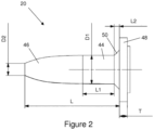
- FIG 2 shows a side view of a valve pin 20 from the gas blender 2 of Figure 1 .
- the valve pin 20 is generally 'bullet shaped', with a generally constant diameter stem portion 44 and a non-linearly tapering point 46 at a first end.
- a larger diameter base 48 is provided at a second end of the valve pin 20, opposite the tapered first end 46, for attachment to a linear motor 24.
- the stem portion 44 extends over a length L1 of around 6mm from the end of a short transition from the larger diameter base 48, and has an outer diameter D1 of 5.35mm.
- the stem portion 44 adjacent the base 48 includes a sealing position, at which the valve pin may form a complete gas-tight seal with an external sealing element such as an o-ring or similar.
- the tapering point 46 has a non-linear taper from the other end of the generally constant diameter stem portion 44 down to an end diameter D2 of 2.3mm.
- the overall length L of the valve pin 20 from the larger diameter base 48 to the end of the tapered point 46 is around 18mm, including the 1mm length L2 of the transition, and the thickness T of the base 48 is around 1.5mm.
- valve pins 20 in the gas blender results in a simpler and more cost-effective valve assembly than using proportional solenoid valves or similar, and also allows the use of stepper motors for control, which provides further benefits as outlined above.
- problems were encountered when trying to maintain the required accuracy and precision that is provided by more complex ventilator based systems, particularly when operating at relatively high inlet pressures and low flow rates.
- the bullet shape of the pin 20 helps to linearize the valve response, but problems still arise when operating at high pressures.
- a small change in the motor position when the pin 20 is close to the O-ring 22 can change the cross-sectional area of the valve dramatically, leading to a loss of control.
- Tapered valve pins and linear motors are most commonly used for opening and closing valves in low pressure LPG systems, and a tapered pin tends to provide adequate flow control during normal use at low pressures.
- medical gas flow controllers such as the gas blender of Figure 1 are required to provide precise flow control at all operating pressures up to at least 6 bar (87psi, 600kPa), and testing found that the required precision/fine control was not obtainable during testing with a standard tapered valve pin.
- the problem could be addressed by including a regulator upstream of the control valves, but this adds complexity to the system and is not desirable.
- Figure 3 shows an end view of the valve pin 20 from the end of the tapering point 46.
- a slit 52 or channel is provided in the side of the valve pin 20.
- the slit 52 has a curved floor 54 within the valve pin 20 and generally parallel spaced sides providing a width W of 0.8mm.
- FIG. 3A A cross-section of the valve pin 20 through the slit 52, as indicated by arrows A-A, is shown in Figure 3A .
- the slit 52 can be seen to vary in depth along the length of the valve pin 20.
- the curved floor 54 of the slit 52 which has a height H of around 0.2mm, extends just beyond the central axis 56 of the valve pin 20.
- the depth of the slit 52 decreases linearly along the length of the valve pin 20 towards the base 48, terminating part way along the constant diameter stem portion 44 at a distance L3 of around 2.4mm from the base 48.
- a central hole 58 in the base portion 48 for mounting the valve pin 20 to a motor 24.
- the inclusion of the slit 52 in the side of the valve pin 20, and its varying depth along the length of the pin 20, allows greater control at high operating pressures.
- the slit 52 provides a path through the valve at a near-sealed position, and provides a larger cross-sectional area for the valve than would otherwise be the case when the pin 20 is close to the O-ring 22.
- the effect of the slit 52 in the pin 20 is low, because the cross-sectional area of the valve is already so large.
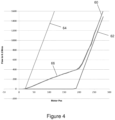
- Figure 4 is a graph of motor position vs flow through a valve for three different valve pins.
- the middle plot 60 of the three illustrates the flow when using the slotted valve pin 20 as described above.
- To the right of the graph is a plot 62 illustrating the flow through a valve having a similar pin without the slit, while the leftmost plot 64 illustrates the performance of a shorter valve pin, specifically a pin with a shorter constant diameter stem portion 44, again without a slit.
- the bullet-shape of the valve pins provides the linear response seen in plots 62 and 64, and for the higher flow rates in plot 60.
- Shortening the length of the bullet addresses the first of these problems, as can be seen in plot 64 where far less of the motor range provides zero flow because the narrowing of the bullet shape would occur at lower opening positions.
- the abrupt change in flow rate caused by the tapered part of the bullet still provides the same difficulties when trying to precisely control low flow rates.
- the lower part 66 of the plot 60 shows where the slit 52 is active, while the upper, steeper part is when the bullet shape takes over.
- the slit 52 provides a relatively gradual increase of flow rate up to about 40 lmin -1 , before the same faster response is provided above this. This allows for more precision when low flows are required (more motor movement for a small change in flow), while still allowing for large flows with less precision.
- the difference can be quantified by comparing the gradients for the two parts of the plot.
- the lower part 66 has a gradient of about 2.
- valve pin 20 becomes less reliant on the physical method of sealing between the casing and the needle/bullet. This physical sealing typically makes the actual opening point very unreliable, which further reduces the precision of typical valve pins at low flow rates.
- Figure 5 shows three overlaid plots showing the relationship between motor position and flow rate for the valve pin 20 at three different supply pressures.
- Plots 68 and 70 relate to supply pressures of 3.5 bar and 2.5 bar respectively, and both show predictable linear performance, similar to that seen in Figure 4 , in both regions of the graph (governed by the slit 52 and bullet shape).
- the third plot 72 relates to a lower supply pressure of 1.5 bar. This is below the normal required operating pressure range for gas blender applications (typically 2-6 bar, and rated to operate at up to 10 bar before failure), but still shows similar performance trends over the majority of the range shown. Indeed, results in testing found improvements for supply pressures as low as 0.5 bar.
- valve pin 20 which provides finer control across a wide range of pressures, the described gas blender no longer needs to include a complex and costly flow regulator. The resulting device is thus simpler and more cost-effective.
- a pin may alternatively be provided with multiple slits, possibly of various depths and shapes. It should also be understood that alternative means of controlling or altering the cross-section of the pin could be provided.
- valve pin 20 is beneficial in linearizing the valve response, but the additional control provided by the slit 52 would also be beneficial if applied to alternative valve pin shapes.
- valve pin 120 An alternative design of valve pin 120 is illustrated in Figures 6 to 9B .
- the alternative valve pin does not comprise a taper 46 on the exterior of the body portion.
- the stem portion 144 comprises an open end section 146 provided by first and second slits or channels 152A,152B which widen and deepen as they extend from the larger diameter base 148, leaving a tapered central part 145 of the valve stem 144.
- This provides the alternative valve pin 120 with a 'duckbill' appearance, as can be seen in Figures 6 and 7 .
- FIG. 8 A front view of the alternative valve pin 120 is shown in Figure 8 .
- the apparent taper at the end of the stem portion 144 is a result of the widening and deepening 152A,152B on either side of the valve stem 144.
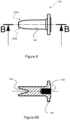
- the open end 146 can clearly be seen in the cross-sectional view of Figure 8B , which is taken at the line B-B in Figure 8 .
- the duckbill shape of the pin 120 is also clearly visible, as is a central hole 158 provided in the base portion 148 for mounting the valve pin 20 to a motor 24
- Figure 9 shows a side view of the alternative valve pin 120, in which the generally straight sides of the valve stem 144 and the flared shape of the first channel 152A can be seen.
- the alternative valve pin 120 was developed, at least in part, to address problems associated with the physical method of sealing between the previously described bullet-shaped valve pin 20 and an external o-ring seal. While the bullet-shaped valve pin 20 achieve a desirable linear response over a range of flows/pressures, some problems still arose at the point the pin separated from or moved off the o-ring.
- the generally constant outer diameter of the alternative pin 120 helps to keep the stem 144 in constant contact with an o-ring or similar seal.
- variable flow area is provided by the flaring of the slits 152A,152B rather than by an external taper.
- Figure 9 also indicates the location of the cross sectional view shown in Figure 9B .
- the tapered shape of the central part 145 of the valve stem 144 can be seen in Figure 9B .
- the curved taper in the illustrated example is provided by a flaring of the first and second channels 152A,152B as they deepen towards the end of the valve pin 120.
- alternative tapers such as a straight taper, could be provided if the first and second channels 152A,152B were not flared as shown.
- the positions and sizes of the first and second channels 152A,152B may be substantially identical. However, in the illustrated example the total length L4 of the first channel 152A is greater than the total length L5 of the second channel 152B, meaning that the first channel 152B starts closer to the base portion 148 than the second channel 152B.
- valve pin 120 abruptly disengages from an o-ring/seal, due to its generally constant external diameter, the flared channels 152A,152B and open end section 146 mean that the valve is largely open at the point of disengagement. Any effect of the abrupt disengagement is therefore minimal, much in the same way that the influence of the slit 52 in the bullet-shaped valve pin 20 is lower when the valve is more open, as previously described.
- valve pin 120 will typically be similar to the valve 20 previously described.
- the length from the larger diameter base 148 to the end of the open end 146 will likely be around 18mm.
- shorter valve pins could be provided, where a comparable dimension may be around 14mm, either by reducing the overall size or by effectively cutting the open end section 146 shorter than shown.
- Figure 10 shows three overlaid plots showing the relationship between motor position and flow rate for the alternative valve pin 120 at three different supply pressures.
- Plot 168 relates to a supply pressure of 6 bar
- plot 170 to a supply pressure of 4 bar
- plot 172 to supply pressure of 2 bar. All three plots 160,170,172 show comparative performance, illustrating the predictability and suitability of the alternative valve pin 120 across the standard operating pressure range of 2-6 bar.
- valve pins 20,120 can be operated using linear stepper motors. This minimises the power drain of the system, because the motors need to be activated only when movement of the valve pin 20,120 is required, and means that the valves will remain in position, maintaining a desired flow rate, if power to the unit is interrupted.
- valve pins 20,120 provides the required level of precision in a dedicated system which avoids the unnecessary complexity found in many ventilators and removes the requirement for a regulator.
- the valve pins are described herein provide turndown ratios of 1500:1 and 5000:1, while also being relatively simple to manufacture. Alternative valve arrangements with a suitably high turndown ratio may, however, also provide similar benefits and allow implementation of the flow control and gas blender aspects of the invention.
- precision manufactured bell-shaped valves are available that claim to provide turndown ratios of around 10,000:1.
- the rotating discs may be driven by stepper motors in the same way as the valve pins 20,120 already described.
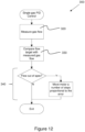
- FIGS 11 and 12 are flow charts setting out elements of control strategies that are applicable to various aspects of the disclosure.
- the control strategies as shown are iterative in a closed loop.
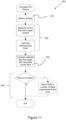
- Figure 11 illustrates a suitable control strategy 200 for a gas blender according to the disclosure.
- Control of the gas flow using, for example, a motorised valve pin 20,120 as previously described is done using a software-controlled stepper motor in a closed loop.
- the output flow is compared with the target flow 230 and the difference is used to modify the position of the pin 240, thus changing the output flow.
- the gas blender controls two gasses independently to achieve a selected flow and oxygen concentration, with each gas being checked in turn against the target flow for that gas.
- the control method 200 therefore first selects a gas for measurement 210 before implementing analysis 220 and comparison 230 steps and controlling a motor based on the comparison 240.
- control loop was found suitable for the control loop to be executed every 200 ms, to suit the speed of a flow sensor used in a particular medical gas blender.
- different repeat rates/frequencies could be used depending on the needs of a particular flow sensor and/or of a particular flow control device.
- a similar control method can also be used to measure and control the flow of a single gas, for example in a medical flowmeter/regulator, as illustrated in Figure 12 .
- the flowchart of Figure 12 shows a simplified method 300 including the steps of measuring a gas flow 320 and comparing with a target value 330.
- a motor is then moved a number of steps based on the comparison 340. Again, this is executed every 200 ms, or at a different frequency if a particular application requires.
- a further simplified version of the control loop/method 300 could be provided. Instead of moving the motor a number of steps proportional to the error at 340, it would be possible to just move the motor one step and measure again, moving one further step if the error hasn't been corrected. The simplification comes at the expense of a slower response time.
Landscapes
- Health & Medical Sciences (AREA)
- Engineering & Computer Science (AREA)
- General Health & Medical Sciences (AREA)
- Heart & Thoracic Surgery (AREA)
- Veterinary Medicine (AREA)
- Public Health (AREA)
- Animal Behavior & Ethology (AREA)
- Emergency Medicine (AREA)
- Pulmonology (AREA)
- Anesthesiology (AREA)
- Biomedical Technology (AREA)
- Life Sciences & Earth Sciences (AREA)
- Hematology (AREA)
- General Engineering & Computer Science (AREA)
- Mechanical Engineering (AREA)
- Automation & Control Theory (AREA)
- General Physics & Mathematics (AREA)
- Physics & Mathematics (AREA)
- Accessories For Mixers (AREA)
- Flow Control (AREA)
- Multiple-Way Valves (AREA)
Claims (15)
- Medizinischer Gasmischer (2), umfassend:einen ersten Einlass (6) zum Anschluss an eine erste Gasversorgung,einen zweiten Einlass (6) zum Anschluss an eine zweite Gasversorgung;eine Mischkammer (14);ein erstes Durchflussregelventil (20,22,24), das sich zwischen dem ersten Einlass (6) und der Mischkammer (14) zum Steuern des Flusses eines ersten Gases zur Mischkammer (14) befindet;ein zweites Durchflussregelventil (20,22,24), das sich zwischen dem zweiten Einlass (6) und der Mischkammer (14) zum Steuern des Flusses eines zweiten Gases zur Mischkammer (14) befindet;einen Auslass (16); undSteuerhardware (200) zum Steuern des Betriebs des ersten und zweiten Durchflussregelventils (20,22,24), um den Fluss des ersten und zweiten Gases unabhängig zu steuern;dadurch gekennzeichnet, dass das erste und zweite Durchflussregelventil (20,22,24) ein Regelverhältnis von mehr als 1000:1 aufweisen.
- Medizinischer Gasmischer (2) nach Anspruch 1, wobei die Steuerhardware (200) so konfiguriert ist, dass sie einen Messschritt (220), in dem ein Gasfluss gemessen wird, und einen Vergleichsschritt (230) durchführt, in dem der gemessene Gasfluss mit einem Zielfluss verglichen wird.
- Medizinischer Gasmischer (2) nach Anspruch 2, wobei die Steuerhardware (200) so konfiguriert ist, dass sie vor dem Messschritt (220) einen Gasfluss (210) auswählt.
- Medizinischer Gasmischer (2) nach Anspruch 2 oder 3, wobei die Steuerhardware (200) so konfiguriert ist, dass sie im Rahmen des Messschritts (220) zusätzlich den Sauerstoffgehalt misst und einzelne Gasflüsse berechnet.
- Medizinischer Gasmischer (2) nach Anspruch 4, wobei mindestens eines von dem ersten und zweiten Durchflussregelventil (20,22,24) ein Ventilelement (20) umfasst, das von einem Motor (24) angetrieben wird, und wobei die Steuerhardware (200) so konfiguriert ist, dass sie den Motor basierend auf dem Ergebnis des Vergleichsschritts (230) um eine Anzahl von Schritten (240) bewegt.
- Medizinischer Gasmischer (2) nach Anspruch 5, wobei das Ventilelement (20) einen Ventilstift umfasst.
- Medizinischer Gasmischer (2) nach Anspruch 6, wobei der Ventilstift (20) einen länglichen Körper (44, 144) mit einem ersten Ende und einem zweiten, freien Ende entfernt vom ersten Ende, einer äußeren Dichtfläche und einen verjüngten Teil (46, 145) umfasst, der sich zum zweiten Ende des Körpers (44, 144) hin verjüngt, wobei eine Dichtposition zum ersten Ende des Ventilkörpers (44, 144) hin vorgesehen ist, und wobei der Ventilstift (20) so geformt ist, dass er den Durchflussquerschnitt des Ventils (20,22,24) nahe der Dichtposition vergrößert.
- Medizinischer Gasmischer (2) nach Anspruch 7, wobei in der äußeren Dichtfläche des Körpers (44, 144) nahe der Dichtposition eine Aussparung (52, 152) vorgesehen ist.
- Medizinischer Gasmischer (2) nach Anspruch 8, wobei die Aussparung (52, 152) einen länglichen Kanal oder Schlitz umfasst, wobei die Länge des Schlitzes auf die Länge des länglichen Körpers (44, 144) abgestimmt ist.
- Medizinischer Gasmischer (2) nach Anspruch 9, wobei die Tiefe des länglichen Schlitzes (52, 152) entlang der Länge des Schlitzes (52, 152) variiert.
- Medizinischer Gasmischer (2) nach Anspruch 10, wobei die äußere Dichtfläche einen im Wesentlichen konstanten Querschnitt aufweist und der verjüngte Teil (145) des Körpers durch die Variation der Tiefe des länglichen Schlitzes (152) vorgesehen ist.
- Medizinischer Gasmischer (2) nach Anspruch 11, wobei der längliche Schlitz (152) zum freien Ende des Körpers hin aufgeweitet ist und vorzugsweise einen offenen Endabschnitt (146) am freien Ende des Körpers bereitstellt.
- Medizinischer Gasmischer (2) nach Anspruch 11 oder 12, wobei ein erster und zweiter länglicher Schlitz (152A, 152B) vorgesehen sind und wobei der verjüngte Teil des Körpers eine gekrümmte Verjüngung umfasst, die durch das Aufweiten des ersten und zweiten länglichen Schlitzes (152A, 152B) vorgesehen ist, während sie sich zum freien Ende des Ventilstifts (120) hin vertiefen.
- Medizinischer Gasmischer (2) nach einem der Ansprüche 8 bis 13, wobei eine erster und zweiter länglicher Schlitz (152A, 152B) vorgesehen sind und wobei die Länge des ersten länglichen Schlitzes (152A) vorzugsweise größer als die Länge des ersten länglichen Schlitzes (152B) ist.
- Beatmungskreislauf, umfassend einen medizinischen Gasmischer (2) nach einem der Ansprüche 1 bis 14.
Priority Applications (1)
| Application Number | Priority Date | Filing Date | Title |
|---|---|---|---|
| EP23192251.9A EP4249027B1 (de) | 2018-01-10 | 2019-01-10 | Ventil für einen gasstromregler |
Applications Claiming Priority (2)
| Application Number | Priority Date | Filing Date | Title |
|---|---|---|---|
| GBGB1800394.7A GB201800394D0 (en) | 2018-01-10 | 2018-01-10 | A gas flow controller and a valve pin for a gas flow controller |
| PCT/EP2019/050598 WO2019138020A1 (en) | 2018-01-10 | 2019-01-10 | A gas flow controller and a valve pin for a gas flow controller |
Related Child Applications (1)
| Application Number | Title | Priority Date | Filing Date |
|---|---|---|---|
| EP23192251.9A Division EP4249027B1 (de) | 2018-01-10 | 2019-01-10 | Ventil für einen gasstromregler |
Publications (2)
| Publication Number | Publication Date |
|---|---|
| EP3737448A1 EP3737448A1 (de) | 2020-11-18 |
| EP3737448B1 true EP3737448B1 (de) | 2023-09-20 |
Family
ID=61190439
Family Applications (2)
| Application Number | Title | Priority Date | Filing Date |
|---|---|---|---|
| EP19701300.6A Active EP3737448B1 (de) | 2018-01-10 | 2019-01-10 | Gasstromregler und ventilstift für einen gasstromregler |
| EP23192251.9A Active EP4249027B1 (de) | 2018-01-10 | 2019-01-10 | Ventil für einen gasstromregler |
Family Applications After (1)
| Application Number | Title | Priority Date | Filing Date |
|---|---|---|---|
| EP23192251.9A Active EP4249027B1 (de) | 2018-01-10 | 2019-01-10 | Ventil für einen gasstromregler |
Country Status (7)
| Country | Link |
|---|---|
| US (1) | US12582795B2 (de) |
| EP (2) | EP3737448B1 (de) |
| JP (1) | JP2021510334A (de) |
| CN (1) | CN111565784A (de) |
| ES (2) | ES2963517T3 (de) |
| GB (3) | GB201800394D0 (de) |
| WO (1) | WO2019138020A1 (de) |
Families Citing this family (5)
| Publication number | Priority date | Publication date | Assignee | Title |
|---|---|---|---|---|
| DE102020002278A1 (de) * | 2019-04-24 | 2020-10-29 | Löwenstein Medical Technology S.A. | System zur Atemgasversorgung und Verfahren |
| KR102659350B1 (ko) * | 2022-02-15 | 2024-04-22 | (주)오토일렉스 | 유로 전환 밸브 |
| CN117065201A (zh) * | 2022-05-08 | 2023-11-17 | 深圳市美好创亿医疗科技股份有限公司 | 流量调节阀及呼气no检测系统 |
| CN114931687B (zh) * | 2022-05-19 | 2023-05-23 | 四川大学华西医院 | 麻醉科用浓度可调节式麻醉装置 |
| US20250234799A1 (en) * | 2024-01-19 | 2025-07-24 | Capstan Ag Systems, Inc. | Valve assembly including traveler with slotted plunger and agricultural fluid application systems including same |
Family Cites Families (29)
| Publication number | Priority date | Publication date | Assignee | Title |
|---|---|---|---|---|
| US2516825A (en) * | 1945-02-19 | 1950-07-25 | Meriam Instr Company | Metering valve |
| US3511470A (en) * | 1968-02-12 | 1970-05-12 | Beckett Harcum Co | Needle valve |
| SE370331B (de) * | 1973-02-07 | 1974-10-14 | Lkb Medical Ab | |
| US4237925A (en) * | 1977-01-18 | 1980-12-09 | Citizen Watch Co., Ltd. | Anesthesia apparatus |
| JPS60263784A (ja) | 1984-06-12 | 1985-12-27 | Chiyoda Chem Eng & Constr Co Ltd | パルスモ−タを用いた制御弁 |
| KR950009539Y1 (ko) * | 1992-09-08 | 1995-11-08 | 이승춘 | 유량조절밸브 |
| US5411019A (en) * | 1993-11-03 | 1995-05-02 | North American Drager | Integrated oxygen ratio controller |
| US5544674A (en) * | 1995-07-14 | 1996-08-13 | Infrasonics, Inc. | Gas mixing apparatus for respirator |
| US5887611A (en) * | 1996-12-31 | 1999-03-30 | The University Of Florida | Gas blender |
| US6062256A (en) | 1997-02-11 | 2000-05-16 | Engineering Measurements Company | Micro mass flow control apparatus and method |
| US5901746A (en) * | 1997-10-03 | 1999-05-11 | Tetra Laval Holdings & Finance,Sa | Controlled flow filling system |
| JP2001004062A (ja) | 1999-06-17 | 2001-01-09 | Benkan Corp | 流量制御用バルブ |
| US7234680B2 (en) * | 2001-05-31 | 2007-06-26 | Wendell Hull | Combination valve and regulator with vented seat for use with pressurized gas cylinders, particularly oxygen cylinders |
| US6953056B1 (en) * | 2003-02-26 | 2005-10-11 | Chrisp Lynn E | Metering valve assembly |
| KR200376936Y1 (ko) * | 2004-12-01 | 2005-03-08 | 김재선 | 유량조절구조를 갖는 온수분배기용 밸브 |
| IL169132A (en) * | 2005-06-14 | 2008-12-29 | Yossi Dana | Magnetic fluid flow controller |
| JP4253333B2 (ja) * | 2006-07-12 | 2009-04-08 | 有限会社浜インターナショナル | スピードコントローラ |
| CN101720215B (zh) * | 2007-05-30 | 2014-03-26 | 伊尔贝特·雅各布斯·库珀斯 | 对电可操作的复苏器的改进 |
| CN101664575B (zh) * | 2009-09-04 | 2011-09-21 | 深圳市安保科技有限公司 | 调节呼吸流量的装置和呼吸机 |
| GB2485417B (en) * | 2010-11-15 | 2018-07-18 | Oellgaard Jensen Frede | Reversible proportional fluid control valve |
| ES2657841T3 (es) | 2011-02-17 | 2018-03-07 | Linde Ag | Mezclador de gases y método para mezclar al menos dos gases diferentes |
| US20120318263A1 (en) * | 2011-06-16 | 2012-12-20 | General Electric Company | Anesthesia vaporizer system and method |
| CN102853128B (zh) * | 2011-06-27 | 2014-05-14 | 浙江三花股份有限公司 | 一种流量调节阀 |
| CN103083772B (zh) * | 2011-10-27 | 2016-01-20 | 北京谊安医疗系统股份有限公司 | 麻醉机及其流量计 |
| ITMI20120289A1 (it) * | 2012-02-27 | 2013-08-28 | Dropsa Spa | Dispositivo di lubrificazione con regolazione della portata di lubrificante fluido |
| CN103591351A (zh) * | 2012-10-18 | 2014-02-19 | 北京熊川阀门制造有限公司 | 一种调节阀 |
| DE102015214141A1 (de) * | 2015-07-27 | 2017-02-02 | Daniel Peller | Atemtherapiegerät |
| JP6692213B2 (ja) * | 2016-05-23 | 2020-05-13 | 株式会社不二工機 | 流量調整弁 |
| US10394254B2 (en) * | 2016-05-26 | 2019-08-27 | Sko Flo Industries, Inc. | Multi-stage flow control assemblies |
-
2018
- 2018-01-10 GB GBGB1800394.7A patent/GB201800394D0/en not_active Ceased
-
2019
- 2019-01-10 ES ES19701300T patent/ES2963517T3/es active Active
- 2019-01-10 CN CN201980008089.7A patent/CN111565784A/zh active Pending
- 2019-01-10 JP JP2020538595A patent/JP2021510334A/ja active Pending
- 2019-01-10 ES ES23192251T patent/ES3025710T3/es active Active
- 2019-01-10 US US16/961,095 patent/US12582795B2/en active Active
- 2019-01-10 WO PCT/EP2019/050598 patent/WO2019138020A1/en not_active Ceased
- 2019-01-10 EP EP19701300.6A patent/EP3737448B1/de active Active
- 2019-01-10 GB GB1900366.4A patent/GB2572037B/en active Active
- 2019-01-10 EP EP23192251.9A patent/EP4249027B1/de active Active
- 2019-01-10 GB GB2115308.5A patent/GB2597620B/en active Active
Also Published As
| Publication number | Publication date |
|---|---|
| GB201800394D0 (en) | 2018-02-21 |
| EP4249027A3 (de) | 2023-10-18 |
| GB2597620B (en) | 2022-08-31 |
| GB2597620A (en) | 2022-02-02 |
| GB202115308D0 (en) | 2021-12-08 |
| WO2019138020A1 (en) | 2019-07-18 |
| EP3737448A1 (de) | 2020-11-18 |
| EP4249027B1 (de) | 2025-01-22 |
| GB2572037B (en) | 2022-01-12 |
| EP4249027A2 (de) | 2023-09-27 |
| CN111565784A (zh) | 2020-08-21 |
| ES2963517T3 (es) | 2024-03-27 |
| US12582795B2 (en) | 2026-03-24 |
| GB2572037A (en) | 2019-09-18 |
| US20200353202A1 (en) | 2020-11-12 |
| ES3025710T3 (en) | 2025-06-09 |
| GB201900366D0 (en) | 2019-02-27 |
| JP2021510334A (ja) | 2021-04-22 |
Similar Documents
| Publication | Publication Date | Title |
|---|---|---|
| EP4249027B1 (de) | Ventil für einen gasstromregler | |
| US6622753B2 (en) | Variable pressure regulated flow controllers | |
| KR101936189B1 (ko) | 압력 균형화 밸브 | |
| JP3801570B2 (ja) | 流量制御装置 | |
| KR101930304B1 (ko) | 유량계 | |
| ES2927632T3 (es) | Dispositivo para el suministro de agua con regulación de caudal y temperatura y métodos para su utilización | |
| EP3568184B1 (de) | Fernanpassung des sauerstoffflusses | |
| CN101539782B (zh) | 流量控制装置 | |
| JP2004517396A (ja) | 圧力型マスフローコントローラシステム | |
| JPH0778032A (ja) | 流体の流量を変化させる弁装置 | |
| JP2005196788A (ja) | 流体の流量を制御する装置、方法及びシステム | |
| CN102128285B (zh) | 一种气体比例配比阀、多元气体比例配比组合阀以及气体混配系统 | |
| US20100000609A1 (en) | Fluid mixtures | |
| EP1775504A1 (de) | Servo-positionierer für ein mikroreglerventil | |
| US12434958B2 (en) | Metering device for adjusting and/or controlling a gas flow, method for adjusting and/or controlling a gas flow, and domestic appliance assembly | |
| US11513540B2 (en) | Pressure compensated flow controller with only two pressures | |
| JP2015197728A (ja) | 整圧装置 | |
| JP2024077140A (ja) | 流量制御弁および流量制御装置 | |
| RU36053U1 (ru) | Регулятор расхода | |
| JPH0413582B2 (de) | ||
| RU122929U1 (ru) | Газовый смеситель | |
| JPS62155384A (ja) | 流体制御装置 | |
| IL166167A (en) | Device, method, and system for controlling fluid flow |
Legal Events
| Date | Code | Title | Description |
|---|---|---|---|
| STAA | Information on the status of an ep patent application or granted ep patent |
Free format text: STATUS: UNKNOWN |
|
| STAA | Information on the status of an ep patent application or granted ep patent |
Free format text: STATUS: THE INTERNATIONAL PUBLICATION HAS BEEN MADE |
|
| PUAI | Public reference made under article 153(3) epc to a published international application that has entered the european phase |
Free format text: ORIGINAL CODE: 0009012 |
|
| STAA | Information on the status of an ep patent application or granted ep patent |
Free format text: STATUS: REQUEST FOR EXAMINATION WAS MADE |
|
| 17P | Request for examination filed |
Effective date: 20200810 |
|
| AK | Designated contracting states |
Kind code of ref document: A1 Designated state(s): AL AT BE BG CH CY CZ DE DK EE ES FI FR GB GR HR HU IE IS IT LI LT LU LV MC MK MT NL NO PL PT RO RS SE SI SK SM TR |
|
| AX | Request for extension of the european patent |
Extension state: BA ME |
|
| DAV | Request for validation of the european patent (deleted) | ||
| DAX | Request for extension of the european patent (deleted) | ||
| RAP3 | Party data changed (applicant data changed or rights of an application transferred) |
Owner name: INTERSURGICAL AG |
|
| STAA | Information on the status of an ep patent application or granted ep patent |
Free format text: STATUS: EXAMINATION IS IN PROGRESS |
|
| 17Q | First examination report despatched |
Effective date: 20220621 |
|
| GRAP | Despatch of communication of intention to grant a patent |
Free format text: ORIGINAL CODE: EPIDOSNIGR1 |
|
| STAA | Information on the status of an ep patent application or granted ep patent |
Free format text: STATUS: GRANT OF PATENT IS INTENDED |
|
| INTG | Intention to grant announced |
Effective date: 20230502 |
|
| GRAS | Grant fee paid |
Free format text: ORIGINAL CODE: EPIDOSNIGR3 |
|
| GRAA | (expected) grant |
Free format text: ORIGINAL CODE: 0009210 |
|
| STAA | Information on the status of an ep patent application or granted ep patent |
Free format text: STATUS: THE PATENT HAS BEEN GRANTED |
|
| AK | Designated contracting states |
Kind code of ref document: B1 Designated state(s): AL AT BE BG CH CY CZ DE DK EE ES FI FR GB GR HR HU IE IS IT LI LT LU LV MC MK MT NL NO PL PT RO RS SE SI SK SM TR |
|
| REG | Reference to a national code |
Ref country code: GB Ref legal event code: FG4D |
|
| REG | Reference to a national code |
Ref country code: CH Ref legal event code: EP |
|
| REG | Reference to a national code |
Ref country code: IE Ref legal event code: FG4D |
|
| REG | Reference to a national code |
Ref country code: DE Ref legal event code: R096 Ref document number: 602019037765 Country of ref document: DE |
|
| P01 | Opt-out of the competence of the unified patent court (upc) registered |
Effective date: 20230908 |
|
| REG | Reference to a national code |
Ref country code: LT Ref legal event code: MG9D |
|
| PG25 | Lapsed in a contracting state [announced via postgrant information from national office to epo] |
Ref country code: GR Free format text: LAPSE BECAUSE OF FAILURE TO SUBMIT A TRANSLATION OF THE DESCRIPTION OR TO PAY THE FEE WITHIN THE PRESCRIBED TIME-LIMIT Effective date: 20231221 |
|
| REG | Reference to a national code |
Ref country code: NL Ref legal event code: MP Effective date: 20230920 |
|
| PG25 | Lapsed in a contracting state [announced via postgrant information from national office to epo] |
Ref country code: SE Free format text: LAPSE BECAUSE OF FAILURE TO SUBMIT A TRANSLATION OF THE DESCRIPTION OR TO PAY THE FEE WITHIN THE PRESCRIBED TIME-LIMIT Effective date: 20230920 Ref country code: RS Free format text: LAPSE BECAUSE OF FAILURE TO SUBMIT A TRANSLATION OF THE DESCRIPTION OR TO PAY THE FEE WITHIN THE PRESCRIBED TIME-LIMIT Effective date: 20230920 Ref country code: NO Free format text: LAPSE BECAUSE OF FAILURE TO SUBMIT A TRANSLATION OF THE DESCRIPTION OR TO PAY THE FEE WITHIN THE PRESCRIBED TIME-LIMIT Effective date: 20231220 Ref country code: LV Free format text: LAPSE BECAUSE OF FAILURE TO SUBMIT A TRANSLATION OF THE DESCRIPTION OR TO PAY THE FEE WITHIN THE PRESCRIBED TIME-LIMIT Effective date: 20230920 Ref country code: LT Free format text: LAPSE BECAUSE OF FAILURE TO SUBMIT A TRANSLATION OF THE DESCRIPTION OR TO PAY THE FEE WITHIN THE PRESCRIBED TIME-LIMIT Effective date: 20230920 Ref country code: HR Free format text: LAPSE BECAUSE OF FAILURE TO SUBMIT A TRANSLATION OF THE DESCRIPTION OR TO PAY THE FEE WITHIN THE PRESCRIBED TIME-LIMIT Effective date: 20230920 Ref country code: GR Free format text: LAPSE BECAUSE OF FAILURE TO SUBMIT A TRANSLATION OF THE DESCRIPTION OR TO PAY THE FEE WITHIN THE PRESCRIBED TIME-LIMIT Effective date: 20231221 Ref country code: FI Free format text: LAPSE BECAUSE OF FAILURE TO SUBMIT A TRANSLATION OF THE DESCRIPTION OR TO PAY THE FEE WITHIN THE PRESCRIBED TIME-LIMIT Effective date: 20230920 |
|
| REG | Reference to a national code |
Ref country code: AT Ref legal event code: MK05 Ref document number: 1612930 Country of ref document: AT Kind code of ref document: T Effective date: 20230920 |
|
| PG25 | Lapsed in a contracting state [announced via postgrant information from national office to epo] |
Ref country code: NL Free format text: LAPSE BECAUSE OF FAILURE TO SUBMIT A TRANSLATION OF THE DESCRIPTION OR TO PAY THE FEE WITHIN THE PRESCRIBED TIME-LIMIT Effective date: 20230920 |
|
| REG | Reference to a national code |
Ref country code: ES Ref legal event code: FG2A Ref document number: 2963517 Country of ref document: ES Kind code of ref document: T3 Effective date: 20240327 |
|
| PG25 | Lapsed in a contracting state [announced via postgrant information from national office to epo] |
Ref country code: IS Free format text: LAPSE BECAUSE OF FAILURE TO SUBMIT A TRANSLATION OF THE DESCRIPTION OR TO PAY THE FEE WITHIN THE PRESCRIBED TIME-LIMIT Effective date: 20240120 |
|
| PG25 | Lapsed in a contracting state [announced via postgrant information from national office to epo] |
Ref country code: AT Free format text: LAPSE BECAUSE OF FAILURE TO SUBMIT A TRANSLATION OF THE DESCRIPTION OR TO PAY THE FEE WITHIN THE PRESCRIBED TIME-LIMIT Effective date: 20230920 |
|
| PG25 | Lapsed in a contracting state [announced via postgrant information from national office to epo] |
Ref country code: SM Free format text: LAPSE BECAUSE OF FAILURE TO SUBMIT A TRANSLATION OF THE DESCRIPTION OR TO PAY THE FEE WITHIN THE PRESCRIBED TIME-LIMIT Effective date: 20230920 Ref country code: RO Free format text: LAPSE BECAUSE OF FAILURE TO SUBMIT A TRANSLATION OF THE DESCRIPTION OR TO PAY THE FEE WITHIN THE PRESCRIBED TIME-LIMIT Effective date: 20230920 Ref country code: IS Free format text: LAPSE BECAUSE OF FAILURE TO SUBMIT A TRANSLATION OF THE DESCRIPTION OR TO PAY THE FEE WITHIN THE PRESCRIBED TIME-LIMIT Effective date: 20240120 Ref country code: EE Free format text: LAPSE BECAUSE OF FAILURE TO SUBMIT A TRANSLATION OF THE DESCRIPTION OR TO PAY THE FEE WITHIN THE PRESCRIBED TIME-LIMIT Effective date: 20230920 Ref country code: CZ Free format text: LAPSE BECAUSE OF FAILURE TO SUBMIT A TRANSLATION OF THE DESCRIPTION OR TO PAY THE FEE WITHIN THE PRESCRIBED TIME-LIMIT Effective date: 20230920 Ref country code: AT Free format text: LAPSE BECAUSE OF FAILURE TO SUBMIT A TRANSLATION OF THE DESCRIPTION OR TO PAY THE FEE WITHIN THE PRESCRIBED TIME-LIMIT Effective date: 20230920 Ref country code: PT Free format text: LAPSE BECAUSE OF FAILURE TO SUBMIT A TRANSLATION OF THE DESCRIPTION OR TO PAY THE FEE WITHIN THE PRESCRIBED TIME-LIMIT Effective date: 20240122 Ref country code: SK Free format text: LAPSE BECAUSE OF FAILURE TO SUBMIT A TRANSLATION OF THE DESCRIPTION OR TO PAY THE FEE WITHIN THE PRESCRIBED TIME-LIMIT Effective date: 20230920 |
|
| PG25 | Lapsed in a contracting state [announced via postgrant information from national office to epo] |
Ref country code: PL Free format text: LAPSE BECAUSE OF FAILURE TO SUBMIT A TRANSLATION OF THE DESCRIPTION OR TO PAY THE FEE WITHIN THE PRESCRIBED TIME-LIMIT Effective date: 20230920 |
|
| REG | Reference to a national code |
Ref country code: DE Ref legal event code: R097 Ref document number: 602019037765 Country of ref document: DE |
|
| PG25 | Lapsed in a contracting state [announced via postgrant information from national office to epo] |
Ref country code: DK Free format text: LAPSE BECAUSE OF FAILURE TO SUBMIT A TRANSLATION OF THE DESCRIPTION OR TO PAY THE FEE WITHIN THE PRESCRIBED TIME-LIMIT Effective date: 20230920 |
|
| PLBE | No opposition filed within time limit |
Free format text: ORIGINAL CODE: 0009261 |
|
| STAA | Information on the status of an ep patent application or granted ep patent |
Free format text: STATUS: NO OPPOSITION FILED WITHIN TIME LIMIT |
|
| PG25 | Lapsed in a contracting state [announced via postgrant information from national office to epo] |
Ref country code: DK Free format text: LAPSE BECAUSE OF FAILURE TO SUBMIT A TRANSLATION OF THE DESCRIPTION OR TO PAY THE FEE WITHIN THE PRESCRIBED TIME-LIMIT Effective date: 20230920 |
|
| PG25 | Lapsed in a contracting state [announced via postgrant information from national office to epo] |
Ref country code: MC Free format text: LAPSE BECAUSE OF FAILURE TO SUBMIT A TRANSLATION OF THE DESCRIPTION OR TO PAY THE FEE WITHIN THE PRESCRIBED TIME-LIMIT Effective date: 20230920 |
|
| 26N | No opposition filed |
Effective date: 20240621 |
|
| PG25 | Lapsed in a contracting state [announced via postgrant information from national office to epo] |
Ref country code: MC Free format text: LAPSE BECAUSE OF FAILURE TO SUBMIT A TRANSLATION OF THE DESCRIPTION OR TO PAY THE FEE WITHIN THE PRESCRIBED TIME-LIMIT Effective date: 20230920 |
|
| REG | Reference to a national code |
Ref country code: CH Ref legal event code: PL |
|
| PG25 | Lapsed in a contracting state [announced via postgrant information from national office to epo] |
Ref country code: LU Free format text: LAPSE BECAUSE OF NON-PAYMENT OF DUE FEES Effective date: 20240110 |
|
| PG25 | Lapsed in a contracting state [announced via postgrant information from national office to epo] |
Ref country code: LU Free format text: LAPSE BECAUSE OF NON-PAYMENT OF DUE FEES Effective date: 20240110 |
|
| PG25 | Lapsed in a contracting state [announced via postgrant information from national office to epo] |
Ref country code: BE Free format text: LAPSE BECAUSE OF NON-PAYMENT OF DUE FEES Effective date: 20240131 |
|
| PG25 | Lapsed in a contracting state [announced via postgrant information from national office to epo] |
Ref country code: CH Free format text: LAPSE BECAUSE OF NON-PAYMENT OF DUE FEES Effective date: 20240131 |
|
| PG25 | Lapsed in a contracting state [announced via postgrant information from national office to epo] |
Ref country code: SI Free format text: LAPSE BECAUSE OF FAILURE TO SUBMIT A TRANSLATION OF THE DESCRIPTION OR TO PAY THE FEE WITHIN THE PRESCRIBED TIME-LIMIT Effective date: 20230920 |
|
| PG25 | Lapsed in a contracting state [announced via postgrant information from national office to epo] |
Ref country code: SI Free format text: LAPSE BECAUSE OF FAILURE TO SUBMIT A TRANSLATION OF THE DESCRIPTION OR TO PAY THE FEE WITHIN THE PRESCRIBED TIME-LIMIT Effective date: 20230920 Ref country code: CH Free format text: LAPSE BECAUSE OF NON-PAYMENT OF DUE FEES Effective date: 20240131 Ref country code: BE Free format text: LAPSE BECAUSE OF NON-PAYMENT OF DUE FEES Effective date: 20240131 |
|
| REG | Reference to a national code |
Ref country code: BE Ref legal event code: MM Effective date: 20240131 |
|
| PG25 | Lapsed in a contracting state [announced via postgrant information from national office to epo] |
Ref country code: BG Free format text: LAPSE BECAUSE OF FAILURE TO SUBMIT A TRANSLATION OF THE DESCRIPTION OR TO PAY THE FEE WITHIN THE PRESCRIBED TIME-LIMIT Effective date: 20230920 |
|
| PG25 | Lapsed in a contracting state [announced via postgrant information from national office to epo] |
Ref country code: BG Free format text: LAPSE BECAUSE OF FAILURE TO SUBMIT A TRANSLATION OF THE DESCRIPTION OR TO PAY THE FEE WITHIN THE PRESCRIBED TIME-LIMIT Effective date: 20230920 |
|
| PG25 | Lapsed in a contracting state [announced via postgrant information from national office to epo] |
Ref country code: IE Free format text: LAPSE BECAUSE OF NON-PAYMENT OF DUE FEES Effective date: 20240110 |
|
| PG25 | Lapsed in a contracting state [announced via postgrant information from national office to epo] |
Ref country code: IE Free format text: LAPSE BECAUSE OF NON-PAYMENT OF DUE FEES Effective date: 20240110 |
|
| PG25 | Lapsed in a contracting state [announced via postgrant information from national office to epo] |
Ref country code: CY Free format text: LAPSE BECAUSE OF FAILURE TO SUBMIT A TRANSLATION OF THE DESCRIPTION OR TO PAY THE FEE WITHIN THE PRESCRIBED TIME-LIMIT; INVALID AB INITIO Effective date: 20190110 |
|
| PG25 | Lapsed in a contracting state [announced via postgrant information from national office to epo] |
Ref country code: HU Free format text: LAPSE BECAUSE OF FAILURE TO SUBMIT A TRANSLATION OF THE DESCRIPTION OR TO PAY THE FEE WITHIN THE PRESCRIBED TIME-LIMIT; INVALID AB INITIO Effective date: 20190110 |
|
| PGFP | Annual fee paid to national office [announced via postgrant information from national office to epo] |
Ref country code: GB Payment date: 20251117 Year of fee payment: 8 |
|
| PGFP | Annual fee paid to national office [announced via postgrant information from national office to epo] |
Ref country code: FR Payment date: 20251117 Year of fee payment: 8 |
|
| PGFP | Annual fee paid to national office [announced via postgrant information from national office to epo] |
Ref country code: ES Payment date: 20260220 Year of fee payment: 8 |
|
| PGFP | Annual fee paid to national office [announced via postgrant information from national office to epo] |
Ref country code: DE Payment date: 20251209 Year of fee payment: 8 |
|
| PGFP | Annual fee paid to national office [announced via postgrant information from national office to epo] |
Ref country code: IT Payment date: 20251201 Year of fee payment: 8 |
|
| PGFP | Annual fee paid to national office [announced via postgrant information from national office to epo] |
Ref country code: TR Payment date: 20260107 Year of fee payment: 8 |