EP3737488B1 - Module d'étage de pré-séparateur, séparateur aérosol à plusieurs étages avec ledit module d'étage de pré-séparateur, procédé d'ajout et de fonctionnement - Google Patents
Module d'étage de pré-séparateur, séparateur aérosol à plusieurs étages avec ledit module d'étage de pré-séparateur, procédé d'ajout et de fonctionnement Download PDFInfo
- Publication number
- EP3737488B1 EP3737488B1 EP19716062.5A EP19716062A EP3737488B1 EP 3737488 B1 EP3737488 B1 EP 3737488B1 EP 19716062 A EP19716062 A EP 19716062A EP 3737488 B1 EP3737488 B1 EP 3737488B1
- Authority
- EP
- European Patent Office
- Prior art keywords
- separator
- filter
- liquid
- separator stage
- stage
- Prior art date
- Legal status (The legal status is an assumption and is not a legal conclusion. Google has not performed a legal analysis and makes no representation as to the accuracy of the status listed.)
- Active
Links
Images


Classifications
-
- B—PERFORMING OPERATIONS; TRANSPORTING
- B01—PHYSICAL OR CHEMICAL PROCESSES OR APPARATUS IN GENERAL
- B01D—SEPARATION
- B01D46/00—Filters or filtering processes specially modified for separating dispersed particles from gases or vapours
- B01D46/0027—Filters or filtering processes specially modified for separating dispersed particles from gases or vapours with additional separating or treating functions
- B01D46/0035—Filters or filtering processes specially modified for separating dispersed particles from gases or vapours with additional separating or treating functions by wetting, e.g. using surfaces covered with oil
-
- B—PERFORMING OPERATIONS; TRANSPORTING
- B01—PHYSICAL OR CHEMICAL PROCESSES OR APPARATUS IN GENERAL
- B01D—SEPARATION
- B01D46/00—Filters or filtering processes specially modified for separating dispersed particles from gases or vapours
- B01D46/10—Particle separators, e.g. dust precipitators, using filter plates, sheets or pads having plane surfaces
- B01D46/12—Particle separators, e.g. dust precipitators, using filter plates, sheets or pads having plane surfaces in multiple arrangements
-
- B—PERFORMING OPERATIONS; TRANSPORTING
- B01—PHYSICAL OR CHEMICAL PROCESSES OR APPARATUS IN GENERAL
- B01D—SEPARATION
- B01D46/00—Filters or filtering processes specially modified for separating dispersed particles from gases or vapours
- B01D46/56—Filters or filtering processes specially modified for separating dispersed particles from gases or vapours with multiple filtering elements, characterised by their mutual disposition
- B01D46/62—Filters or filtering processes specially modified for separating dispersed particles from gases or vapours with multiple filtering elements, characterised by their mutual disposition connected in series
-
- B—PERFORMING OPERATIONS; TRANSPORTING
- B01—PHYSICAL OR CHEMICAL PROCESSES OR APPARATUS IN GENERAL
- B01D—SEPARATION
- B01D46/00—Filters or filtering processes specially modified for separating dispersed particles from gases or vapours
- B01D46/56—Filters or filtering processes specially modified for separating dispersed particles from gases or vapours with multiple filtering elements, characterised by their mutual disposition
- B01D46/62—Filters or filtering processes specially modified for separating dispersed particles from gases or vapours with multiple filtering elements, characterised by their mutual disposition connected in series
- B01D46/64—Filters or filtering processes specially modified for separating dispersed particles from gases or vapours with multiple filtering elements, characterised by their mutual disposition connected in series arranged concentrically or coaxially
-
- B—PERFORMING OPERATIONS; TRANSPORTING
- B01—PHYSICAL OR CHEMICAL PROCESSES OR APPARATUS IN GENERAL
- B01D—SEPARATION
- B01D47/00—Separating dispersed particles from gases, air or vapours by liquid as separating agent
- B01D47/02—Separating dispersed particles from gases, air or vapours by liquid as separating agent by passing the gas or air or vapour over or through a liquid bath
- B01D47/028—Separating dispersed particles from gases, air or vapours by liquid as separating agent by passing the gas or air or vapour over or through a liquid bath by directing the gas through a wetted wire mesh or a perforated plate
-
- B—PERFORMING OPERATIONS; TRANSPORTING
- B01—PHYSICAL OR CHEMICAL PROCESSES OR APPARATUS IN GENERAL
- B01D—SEPARATION
- B01D50/00—Combinations of methods or devices for separating particles from gases or vapours
- B01D50/60—Combinations of devices covered by groups B01D46/00 and B01D47/00
-
- B—PERFORMING OPERATIONS; TRANSPORTING
- B01—PHYSICAL OR CHEMICAL PROCESSES OR APPARATUS IN GENERAL
- B01D—SEPARATION
- B01D2247/00—Details relating to the separation of dispersed particles from gases, air or vapours by liquid as separating agent
- B01D2247/04—Regenerating the washing fluid
Definitions
- the separation rates achieved with the separators described above are generally very high, but can still be improved.
- the main filter elements used in the filter stacks i.e. high-performance coalescence filters and HEPA filters, are comparatively expensive, so a decisive factor in reducing costs is the longest possible service life of the filter elements.
- the object of the present invention is therefore to provide a separator of the type described above that can be operated cost-effectively at very high separation rates.
- the filter of the pre-separator stage is sprayed with liquid, as provided according to the invention, considerably larger amounts of aerosol from the raw gas adhere to the moist filter, which results in a noticeable reduction in the load on the main filter elements.
- the efficiency of the pre-separator stage according to the invention with a moistened filter is considerably greater than that of a dry filter, over which humidified raw gas is passed, as described in WO '848.
- Which filter is specifically selected from the two specified filter groups depends on the conditions under which the filter is to be used. The selection is based in particular on the type, size and quantity of the particles to be captured, the flow rate of the raw gas and the process pressures.
- the invention is also particularly suitable for cleaning a relatively dry raw gas from an MQL process.
- the term “raw gas” can include both a uniform gas and a mixture of different gases.
- the term “liquid” in the sense of the invention means both a single liquid and a mixture of different liquid components.
- “Pure gas” refers to a raw gas that is largely or completely free of aerosol.
- the spray nozzles can generally be arranged both upstream and downstream of the filter of the pre-separator stage. However, it is preferred to arrange the spray nozzles downstream of the filter. This allows the filter to be humidified much more effectively, as the moisture gradually penetrates the filter from top to bottom, allowing it to be kept very evenly moist. This increases the effectiveness of the filter.
- the raw gas that passes through the filter absorbs moisture on its way through the filter. In the area downstream of the filter, where there is high humidity due to the spraying of liquid through the spray nozzles, the raw gas becomes further enriched with moisture, which further improves the effectiveness of the aerosol separation on the coalescence filters of the downstream main separator stage. The finer the spray mist that is generated, the better the effects produced in this way. Overall, a significantly improved separation of aerosol from the raw gas is therefore observed compared to conventional separators.
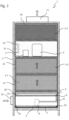
- the nozzle feed line 43 runs within the pre-separator stage 5 according to the invention. This is located in the upper area of the section 20 and thus upstream of the main separator stage 3 with the main filter elements 3-1, 3-2 and 3-3.
- the pre-separator stage 5 is preferably designed as a module, as is shown by way of example in Figure 3 , connected to a pump system of the spray device 4.
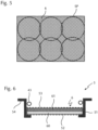
- Figure 6 also shows a cross section along line XX of the Figure 3
- the pre-separator stage 5 or the module comprises a drawer-like housing 50 with a rectangular floor plan.
- the housing 50 has a frame made of four side walls 51, the lower ends of which are preferably bent inwards and form a support surface for a gas-permeable base 52.
- a metal fiber fleece is preferably used as the filter fleece 60
- a spunbonded plastic fleece is preferably used as the filter pad 61, which is finer than the metal fiber fleece but coarser than the subsequent main filter elements 3-1, 3-2 and 3-3.
- the filter 6 is designed in such a way that it meets the classification "Coarse” or "ePM10” according to ISO 16890-1:2017-08. This makes filter 6 suitable for separating larger solid particles that are entrained into the separator by the raw gas.
- the filter 6 also separates liquid impurities from the raw gas when it is moistened with liquid from the liquid reservoir F by means of the spray device 4, as provided according to the invention.
- the separation effect is particularly great when the filter is sprayed with liquid over a large area and as evenly as possible over its entire surface. This is best achieved when several spray nozzles 42 are arranged as evenly as possible above the filter 6, as shown in Figure 3 is shown in a first example.
- the spray nozzles 42 are arranged in two rows that run parallel to the long sides 51 of the housing 50.
- the supply lines 43 which transport liquid to the spray nozzles 42, run along the inside of the side walls 51 and at a small distance from them.
- a cross line connects the two long lines and supplies the two middle spray nozzles, which wet a middle area of the filter 6 with liquid.
- the Figure 3 The routing of the lines 43 shown covers relatively little surface of the filter 6 and thus allows good access to the filter, which significantly simplifies its replacement.
- the entire module with housing 50, supply lines 43 and spray nozzles 42 as well as filter 6 can be removed from the housing 2.
- the line 41 can first be separated from the coupling 44.
- the entire housing 50 with its contents is then pulled forwards out of the housing 2 of the separator 1 like a drawer.
- the holding projections 54 of the module slide along the support beams of the housing 2 (not shown here).
- An optional cover 53 which, like the base 52, is designed to be gas-permeable and offers protection and limitation for the filter 6, is removed or removed from the housing together with the filter 6. Removal of the supply lines 43 is not absolutely necessary, but can also be provided in principle. These components can therefore be replaced or repaired in a simple manner. A complete replacement of the module is also conceivable.
- Figure 4 shows an alternative arrangement of spray nozzles 42 and supply lines 43.
- a central supply line from which three cross lines branch off, to each of which two spray nozzles 42 are attached.
- This variant covers a larger part of the filter surface, so that access to the filter 6 is somewhat more difficult than with the variant of the Figure 3 .
- Any other arrangements of supply lines and spray nozzles are also conceivable within the scope of the invention.
- the filter 6 can be sprayed continuously or at intervals. The latter is preferred for cost reasons.
- the intervals should be chosen so that the filter 6 does not dry out. Suitable intervals can easily be determined by simple tests for the respective process parameters. For example, alternating between 30 seconds of spraying the filter and a 30 second break or spraying processes lasting one minute alternating with 30 seconds break are possible. Whether the filter is in danger of drying out can also be determined using a liquid sensor FS, which is arranged in the liquid reservoir F. The liquid sensor FS measures the level of the liquid in the liquid reservoir. An increase in the liquid level is an indication that the filter 6 is not sufficiently moistened.
- the device can therefore be controlled in such a way that when a predetermined liquid level is exceeded, a signal is sent from the liquid sensor FS to a control device.
- the control device which is either the control device S of the separator or a control device integrated in the pump device, for example in the pump box PK, then causes the spray device to start a wetting process.
- the separator 1 according to the invention also has a temperature control device T in the lower section 20, with which the liquid in the liquid reservoir F can be heated or cooled.
- a temperature control device T in the lower section 20, with which the liquid in the liquid reservoir F can be heated or cooled.
- This can be a film or plate heating or cooling device, which is preferably arranged on the outside of the base plate, which delimits the section 20 at the bottom.
- the temperature control device can be arranged in the feed line to the spray device and comprise a heating and/or cooling device that heats or cools the liquid fed to the spray device.
- a temperature sensor TS is arranged in the liquid reservoir F to measure the temperature of the liquid. This equipment enables the separator according to the invention to set the temperature of the liquid so that the raw gas is cleaned optimally.
- the principle is based on the filter 6, which is sprayed with the tempered liquid, assuming the same temperature as the liquid.
- the filter can thus be brought to a temperature at which the separation of impurities from the raw gas works particularly well.
- the filter 6 can be heated in order to first thaw frozen aerosol particles from very cold raw gas and thus to be able to attach them significantly better to the filter surface.
- hot raw gases can be cooled by cooling the filter 6.
- process parameters such as the amount of liquid sprayed, the size of the liquid particles sprayed, their distribution and the pressure with which the liquid is sprayed can also be adjusted and optimized according to the existing conditions. Control is also carried out via the control device of the pump device and/or the control device S of the separator 1.
- the other process parameters of the separator for example for the area of the main separator stage 3, are set in the manner customary in the state of the art.
- the raw gas entering the separator according to the invention through the inlet 10 first encounters the pre-separator stage 5 according to the invention with the filter 6 moistened with liquid in the first and lowest section 20.
- This not only separates coarse solid particles such as metal particles, soot or similar from the raw gas, but also a portion of the liquid contaminants that settle on the moistened fibers of the filter 6, agglomerate into larger drops and then drip down into the liquid reservoir F.
- the pre-separator stage 5 therefore already frees the raw gas from significantly more contaminants than the pre-filters in separators of the prior art.
- the filter stages downstream then basically correspond to those of the state of the art.
- the main filter elements 3-1 and 3-2 of the main separator stage 3 are preferably coalescence filters with filter elements made of, for example, glass fiber fleece or glass fiber paper, on which liquid contaminants from the raw gas such as oil, coolant or lubricant collect, grow and drip down.
- the liquid dripping from the coalescence filter hits the filter 6 of the pre-separator stage 5 arranged below it and also contributes to its humidification.
- the separated liquid ends up in the liquid reservoir F.
- the final main filter element 3-3 which is preferably a HEPA filter, for example of filter class H13 according to EN 1822, even the finest contaminants such as smoke, bacteria, pollen, spores or similar are removed from the raw gas, so that the clean gas leaving the outlet 11, which is usually air, can be safely released into the environment of the separator 1.
- a HEPA filter for example of filter class H13 according to EN 1822
Landscapes
- Chemical & Material Sciences (AREA)
- Chemical Kinetics & Catalysis (AREA)
- Oil, Petroleum & Natural Gas (AREA)
- Filtering Of Dispersed Particles In Gases (AREA)
- Separating Particles In Gases By Inertia (AREA)
Claims (14)
- Étape de pré-séparateur (5) pouvant être inséré et retirée dans un séparateur (1), conçue en tant que module entièrement préfabriqué, qui présente:- un filtre (6) du groupe de filtration "Coarse" ou "ePM10" conformément à la norme ISO 16890-1:2017- 08,- au moins une buse de pulvérisation (42) pour pulvériser le filtre (6),- au moins une conduite d'alimentation (43) pour alimenter en liquide la buse de pulvérisation (42), au moins au nombre d'une, et- un accouplement (44) pour raccorder la conduite d'alimentation (43), au moins au nombre d'une, à un dispositif de pulvérisation (4) du séparateur (1),caractérisé en ce que
l'étage de pré-séparateur (5) est disposé dans un boîtier (50) en forme de tiroir ayant des parois latérales (51) et un fond (52) perméable aux gaz. - Séparateur (1) destiné à séparer un liquide d'un gaz brut, présentant- un boîtier (2) ayant une entrée (10) pour le gaz brut et une sortie (11) pour le gaz pur,- un étage de séparateur principal (3) ayant au moins un élément filtrant principal (3-1, 3-2, 3-3),- un étage de pré-séparateur (5) située en amont de l'étage de séparateur principal (3), dans lequel l'étage de séparateur principal (3) et l'étage de pré-séparateur (5) sont disposés dans le trajet d'écoulement entre l'entrée (10) et la sortie (11),- un réservoir de liquide (F) ainsi qu'- un dispositif de pulvérisation (4) pour prélever et pulvériser du liquide provenant du réservoir de liquide (F),caractérisé en ce que
l'étage de pré-séparateur (5) est un étage de pré-séparateur selon la revendication 1. - Séparateur ou étage de pré-séparateur selon l'une quelconque des revendications précédentes,
caractérisé en ce que
le filtre (6) comprend un non-tissé filtrant (60) en matière plastique ou en métal, qui est réalisé de préférence à plat et non plié et qui est notamment constitué d'une polyoléfine, de préférence de polyéthylène, d'aluminium, d'acier inoxydable ou d'acier chromé. - Séparateur ou étage de pré-séparateur selon la revendication 3,
caractérisé en ce que
le non-tissé filtrant (60) est recouvert d'un revêtement filtrant (61) qui est choisi de préférence parmi un tissu filtrant, une éponge filtrante, un filtre à lamelles ou un non-tissé filtrant, notamment un filé-lié en matière plastique, dans lequel le revêtement filtrant (61) est plus fin que le non-tissé filtrant (60), mais plus grossier que l'élément filtrant principal (3-1, 3-2, 3-3), au moins au nombre d'un, de l'étage de séparateur principal (3). - Séparateur ou étage de pré-séparateur selon l'une quelconque des revendications précédentes,
caractérisé en ce que
le dispositif de pulvérisation (4) présente une pluralité de buses de pulvérisation (42) réparties en aval et notamment au-dessus du filtre (6), qui sont conçue s pour pulvériser du liquide sur une grande surface de la surface du filtre (6). - Séparateur ou étage de pré-séparateur selon l'une quelconque des revendications précédentes,
caractérisé en ce que
le boîtier (50) en forme de tiroir est pourvu d'un couvercle (53) perméable aux gaz et, optionnellement, de deux saillies de retenue (54) s'étendant depuis des parois latérales (51) opposées. - Séparateur ou étage de pré-séparateur selon la revendication 6,
caractérisé en ce que
la conduite d'alimentation (43), au moins au nombre d'une, est guidée le long d'une paroi latérale (51) à l'intérieur du boîtier (50) en forme de tiroir et s'étend notamment le long de la pluralité, de préférence de la totalité des parois latérales (51). - Séparateur selon l'une quelconque des revendications précédentes, caractérisé en ce qu'
il comprend un dispositif de régulation de température (T) pour régler la température du liquide. - Procédé de mise à jour d'un séparateur (1) destiné à séparer un liquide d'un gaz brut, qui présente:- un boîtier (2) ayant une entrée (10) pour le gaz brut et une sortie (11) pour le gaz pur,- un étage de séparateur principal (3) ayant au moins un élément filtrant principal (3-1, 3-2, 3-3) disposé dans le trajet d'écoulement entre l'entrée (10) et la sortie (11),ayant un étage de pré-séparateur (5) et un dispositif de pulvérisation (4) pour obtenir un séparateur (1) selon l'une quelconque des revendications 2 à 8,caractérisé en ce qu'un étage de pré-séparateur selon l'une quelconque des revendications 1,3 à 7 est inséré en amont de l'étage de séparateur principal (3) dans le trajet d'écoulement.
- Procédé selon la revendication 9,
caractérisé en ce que
l'étage de pré-séparateur, sous la forme d'un tiroir extractible (50), est inséré dans le séparateur (1) et est pourvu à cet effet notamment de saillies de retenue (54) faisant saillie latéralement sur deux parois latérales opposées (51). - Procédé pour opérer un séparateur (1) selon l'une quelconque des revendications 2 à 8,
caractérisé en ce que
le dispositif de pulvérisation (4) est opéré de manière continue ou intermittente au moins pendant l'introduction de gaz brut par l'entrée (10), de sorte que le filtre (6) est mouillé continuellement ou pendant des périodes déterminées avec du liquide. - Procédé selon la revendication 11,
caractérisé en ce que
le liquide s'égouttant du filtre (6) est recueilli dans le réservoir de liquide (F). - Procédé selon la revendication 11 ou 12,
caractérisé en ce que
le niveau de remplissage du réservoir de liquide (F) est déterminé afin de constater si le filtre (6) est suffisamment mouillé de liquide. - Procédé selon l'une quelconque des revendications11 à 13,
caractérisé en ce qu'
il est utilisé pour séparer l'huile de l'air, notamment de l'air évacué de l'industrie de transformation des métaux.
Applications Claiming Priority (2)
| Application Number | Priority Date | Filing Date | Title |
|---|---|---|---|
| DE102018002447.5A DE102018002447A1 (de) | 2018-03-23 | 2018-03-23 | Mehrstufiger Aerosolabscheider, Vorabscheider-Stufen-Modul, Nachrüst- und Betriebsverfahren dafür |
| PCT/EP2019/000087 WO2019179659A1 (fr) | 2018-03-23 | 2019-03-19 | Séparateur aérosol à plusieurs étages, module d'étages de préséparateur, procédé d'ajout et de fonctionnement |
Publications (2)
| Publication Number | Publication Date |
|---|---|
| EP3737488A1 EP3737488A1 (fr) | 2020-11-18 |
| EP3737488B1 true EP3737488B1 (fr) | 2024-07-03 |
Family
ID=66092279
Family Applications (1)
| Application Number | Title | Priority Date | Filing Date |
|---|---|---|---|
| EP19716062.5A Active EP3737488B1 (fr) | 2018-03-23 | 2019-03-19 | Module d'étage de pré-séparateur, séparateur aérosol à plusieurs étages avec ledit module d'étage de pré-séparateur, procédé d'ajout et de fonctionnement |
Country Status (3)
| Country | Link |
|---|---|
| EP (1) | EP3737488B1 (fr) |
| DE (1) | DE102018002447A1 (fr) |
| WO (1) | WO2019179659A1 (fr) |
Families Citing this family (5)
| Publication number | Priority date | Publication date | Assignee | Title |
|---|---|---|---|---|
| DE102019004526B4 (de) * | 2019-07-01 | 2024-03-07 | Tinnit Technologies Gmbh | Staubabscheidevorrichtung, modulare Staubabscheidevorrichtung sowie Verfahren zu deren Verwendung |
| CN111939711A (zh) * | 2020-09-04 | 2020-11-17 | 浙江圣纳智能科技有限公司 | 一种地下工程施工用粉尘雾化沉降装置 |
| DE102020005822A1 (de) | 2020-09-24 | 2022-03-24 | ionotech GmbH | Umluftfilterkasten |
| CN113019042B (zh) * | 2021-03-01 | 2022-07-01 | 湖南利苍环保科技有限公司 | 一种高效自动化废气处理方法 |
| CN113082930B (zh) * | 2021-05-20 | 2022-07-19 | 保定恒冠商品混凝土有限公司 | 一种可除尘的混凝土快速分离装置 |
Citations (1)
| Publication number | Priority date | Publication date | Assignee | Title |
|---|---|---|---|---|
| GB839618A (en) * | 1957-09-05 | 1960-06-29 | Svenska Flaektfabriken Ab | Improvements in air filters |
Family Cites Families (9)
| Publication number | Priority date | Publication date | Assignee | Title |
|---|---|---|---|---|
| DE29612472U1 (de) * | 1996-07-18 | 1997-11-20 | Hör Filtertechnik GmbH, 92637 Weiden | Filtervorrichtung |
| DE19937224A1 (de) | 1999-08-06 | 2001-02-08 | Mannesmann Rexroth Ag | Hydraulische Steueranordnung zur bedarfstromgeregelten (load-sensing-geregelten) Druckmittelversorgung von vorzugsweise mehreren hydraulischen Verbrauchern |
| DE102011122158B4 (de) * | 2011-12-23 | 2019-10-24 | Uwe Athmann | Verfahren und Filtereinrichtung zur Herstellung und Reinigung eines Produktgases |
| US8894748B2 (en) * | 2012-08-21 | 2014-11-25 | Alcoa Inc. | Systems and methods for removing particulate matter from a gas stream |
| JP5805613B2 (ja) * | 2012-11-16 | 2015-11-04 | 株式会社神戸製鋼所 | 改質石炭の製造方法及び改質石炭製造装置 |
| CN203494303U (zh) | 2013-09-13 | 2014-03-26 | 富鼎电子科技(嘉善)有限公司 | 净化装置 |
| WO2016159848A1 (fr) | 2015-04-01 | 2016-10-06 | Nederman Holding Ab | Système de filtration permettant de séparer des impuretés en suspension dans des gaz |
| CN206152546U (zh) * | 2016-08-04 | 2017-05-10 | 广东居峰环保科技有限公司 | 一种小型化高压湿式电除尘器 |
| KR101898674B1 (ko) * | 2017-01-31 | 2018-09-13 | 노호양 | 데미스터 필터를 이용한 흡연시 배출되는 연기, 니코틴, 타르, 유해세균을 제거하는 개인용 이동식 흡연장치 |
-
2018
- 2018-03-23 DE DE102018002447.5A patent/DE102018002447A1/de not_active Ceased
-
2019
- 2019-03-19 WO PCT/EP2019/000087 patent/WO2019179659A1/fr not_active Ceased
- 2019-03-19 EP EP19716062.5A patent/EP3737488B1/fr active Active
Patent Citations (1)
| Publication number | Priority date | Publication date | Assignee | Title |
|---|---|---|---|---|
| GB839618A (en) * | 1957-09-05 | 1960-06-29 | Svenska Flaektfabriken Ab | Improvements in air filters |
Also Published As
| Publication number | Publication date |
|---|---|
| EP3737488A1 (fr) | 2020-11-18 |
| DE102018002447A1 (de) | 2019-09-26 |
| WO2019179659A1 (fr) | 2019-09-26 |
Similar Documents
| Publication | Publication Date | Title |
|---|---|---|
| EP3737488A1 (fr) | Séparateur aérosol à plusieurs étages, module d'étages de préséparateur, procédé d'ajout et de fonctionnement | |
| DE69430271T2 (de) | Filterpatrone zur Nebelabscheidung | |
| DE202006020762U1 (de) | Anlage zum Lackieren von Gegenständen | |
| DE202005003791U1 (de) | Apparatur zur Behandlung von partikelförmigem Gut | |
| DE102015200851A1 (de) | Baugruppe für eine Klimatisierungsanlage | |
| WO2012032003A1 (fr) | Dispositif de filtration et procédé de filtration | |
| EP2749341A1 (fr) | Dispositif et procédé de nettoyage de gaz de fumée d'une installation métallurgique | |
| EP2832241A1 (fr) | Dispositif et procédé de condensation de vapeur dans une chambre à vide | |
| DE102016009487B4 (de) | Abscheideelement, Vorrichtung sowie Verfahren zur Abscheidung von Flüssigkeit aus Rohgas oder aus Rohgasgemisch einer Kraftmaschine oder eines Kompressors | |
| DE112018004424T5 (de) | Austragsverarbeitungseinrichtung für ein Fahrzeugdruckluftbremsenfüllsystem | |
| DE69524739T2 (de) | Die behandlung von gasströmen | |
| EP2117723B1 (fr) | Procede et dispositif destines a eliminer des matieres solides d'une surpulverisation se presentant lors du laquage d'objets | |
| DE112018004396T5 (de) | Austragsverarbeitungseinrichtung und verfahren für ein fahrzeugdruckluftbremsenfüllsystem | |
| DE102015107856B4 (de) | Entfeuchtungsvorrichtung und Entfeuchtungsverfahren | |
| WO2013029910A1 (fr) | Dispositif de conditionnement d'air | |
| DE2800668C3 (de) | Vorrichtung zum Auswaschen von Farbnebel aus der Abluft von Lackieranlagen | |
| DE3217146C2 (fr) | ||
| DE10331998A1 (de) | Vorrichtung zum Filtern von verunreinigten Flüssigkeiten, wie Kühlschmiermittel, insbesondere aus Werkzeugmaschinen | |
| DE102009048062A1 (de) | Wärmeträgerölanlage sowie Verfahren zum Betreiben einer Wärmeträgerölanlage | |
| DE102008029052A1 (de) | Filtervorrichtung | |
| EP3219396B1 (fr) | Installation de peinture et procede de peinture d'une piece ainsi qu'element filtrant a cet effet | |
| EP0932793B1 (fr) | Tuyau traverse par un effluent gazeux faisant partie d'un systeme de tuyaux d'evacuation de gaz, et ledit systeme de tuyaux | |
| DE2726083A1 (de) | Nassreinigungsvorrichtung | |
| EP0191423B1 (fr) | Machine de nettoyage pour le nettoyage à sec d'articles textiles | |
| DE29918704U1 (de) | Fahrbarer Kompakt-Naßabscheider |
Legal Events
| Date | Code | Title | Description |
|---|---|---|---|
| STAA | Information on the status of an ep patent application or granted ep patent |
Free format text: STATUS: UNKNOWN |
|
| STAA | Information on the status of an ep patent application or granted ep patent |
Free format text: STATUS: THE INTERNATIONAL PUBLICATION HAS BEEN MADE |
|
| PUAI | Public reference made under article 153(3) epc to a published international application that has entered the european phase |
Free format text: ORIGINAL CODE: 0009012 |
|
| STAA | Information on the status of an ep patent application or granted ep patent |
Free format text: STATUS: REQUEST FOR EXAMINATION WAS MADE |
|
| 17P | Request for examination filed |
Effective date: 20200812 |
|
| AK | Designated contracting states |
Kind code of ref document: A1 Designated state(s): AL AT BE BG CH CY CZ DE DK EE ES FI FR GB GR HR HU IE IS IT LI LT LU LV MC MK MT NL NO PL PT RO RS SE SI SK SM TR |
|
| AX | Request for extension of the european patent |
Extension state: BA ME |
|
| DAV | Request for validation of the european patent (deleted) | ||
| DAX | Request for extension of the european patent (deleted) | ||
| STAA | Information on the status of an ep patent application or granted ep patent |
Free format text: STATUS: EXAMINATION IS IN PROGRESS |
|
| 17Q | First examination report despatched |
Effective date: 20210719 |
|
| RAP1 | Party data changed (applicant data changed or rights of an application transferred) |
Owner name: MANN+HUMMEL LIFE SCIENCES & ENVIRONMENT GERMANY GMBH |
|
| GRAP | Despatch of communication of intention to grant a patent |
Free format text: ORIGINAL CODE: EPIDOSNIGR1 |
|
| STAA | Information on the status of an ep patent application or granted ep patent |
Free format text: STATUS: GRANT OF PATENT IS INTENDED |
|
| INTG | Intention to grant announced |
Effective date: 20240301 |
|
| GRAS | Grant fee paid |
Free format text: ORIGINAL CODE: EPIDOSNIGR3 |
|
| GRAA | (expected) grant |
Free format text: ORIGINAL CODE: 0009210 |
|
| STAA | Information on the status of an ep patent application or granted ep patent |
Free format text: STATUS: THE PATENT HAS BEEN GRANTED |
|
| AK | Designated contracting states |
Kind code of ref document: B1 Designated state(s): AL AT BE BG CH CY CZ DE DK EE ES FI FR GB GR HR HU IE IS IT LI LT LU LV MC MK MT NL NO PL PT RO RS SE SI SK SM TR |
|
| REG | Reference to a national code |
Ref country code: CH Ref legal event code: EP |
|
| REG | Reference to a national code |
Ref country code: DE Ref legal event code: R096 Ref document number: 502019011574 Country of ref document: DE |
|
| REG | Reference to a national code |
Ref country code: NL Ref legal event code: FP |
|
| REG | Reference to a national code |
Ref country code: LT Ref legal event code: MG9D |
|
| PG25 | Lapsed in a contracting state [announced via postgrant information from national office to epo] |
Ref country code: PT Free format text: LAPSE BECAUSE OF FAILURE TO SUBMIT A TRANSLATION OF THE DESCRIPTION OR TO PAY THE FEE WITHIN THE PRESCRIBED TIME-LIMIT Effective date: 20241104 |
|
| PG25 | Lapsed in a contracting state [announced via postgrant information from national office to epo] |
Ref country code: PT Free format text: LAPSE BECAUSE OF FAILURE TO SUBMIT A TRANSLATION OF THE DESCRIPTION OR TO PAY THE FEE WITHIN THE PRESCRIBED TIME-LIMIT Effective date: 20241104 |
|
| PG25 | Lapsed in a contracting state [announced via postgrant information from national office to epo] |
Ref country code: NO Free format text: LAPSE BECAUSE OF FAILURE TO SUBMIT A TRANSLATION OF THE DESCRIPTION OR TO PAY THE FEE WITHIN THE PRESCRIBED TIME-LIMIT Effective date: 20241003 |
|
| PG25 | Lapsed in a contracting state [announced via postgrant information from national office to epo] |
Ref country code: GR Free format text: LAPSE BECAUSE OF FAILURE TO SUBMIT A TRANSLATION OF THE DESCRIPTION OR TO PAY THE FEE WITHIN THE PRESCRIBED TIME-LIMIT Effective date: 20241004 Ref country code: FI Free format text: LAPSE BECAUSE OF FAILURE TO SUBMIT A TRANSLATION OF THE DESCRIPTION OR TO PAY THE FEE WITHIN THE PRESCRIBED TIME-LIMIT Effective date: 20240703 Ref country code: PL Free format text: LAPSE BECAUSE OF FAILURE TO SUBMIT A TRANSLATION OF THE DESCRIPTION OR TO PAY THE FEE WITHIN THE PRESCRIBED TIME-LIMIT Effective date: 20240703 |
|
| PG25 | Lapsed in a contracting state [announced via postgrant information from national office to epo] |
Ref country code: BG Free format text: LAPSE BECAUSE OF FAILURE TO SUBMIT A TRANSLATION OF THE DESCRIPTION OR TO PAY THE FEE WITHIN THE PRESCRIBED TIME-LIMIT Effective date: 20240703 |
|
| PG25 | Lapsed in a contracting state [announced via postgrant information from national office to epo] |
Ref country code: LV Free format text: LAPSE BECAUSE OF FAILURE TO SUBMIT A TRANSLATION OF THE DESCRIPTION OR TO PAY THE FEE WITHIN THE PRESCRIBED TIME-LIMIT Effective date: 20240703 |
|
| PG25 | Lapsed in a contracting state [announced via postgrant information from national office to epo] |
Ref country code: IS Free format text: LAPSE BECAUSE OF FAILURE TO SUBMIT A TRANSLATION OF THE DESCRIPTION OR TO PAY THE FEE WITHIN THE PRESCRIBED TIME-LIMIT Effective date: 20241103 |
|
| PG25 | Lapsed in a contracting state [announced via postgrant information from national office to epo] |
Ref country code: CZ Free format text: LAPSE BECAUSE OF FAILURE TO SUBMIT A TRANSLATION OF THE DESCRIPTION OR TO PAY THE FEE WITHIN THE PRESCRIBED TIME-LIMIT Effective date: 20240703 Ref country code: HR Free format text: LAPSE BECAUSE OF FAILURE TO SUBMIT A TRANSLATION OF THE DESCRIPTION OR TO PAY THE FEE WITHIN THE PRESCRIBED TIME-LIMIT Effective date: 20240703 |
|
| PG25 | Lapsed in a contracting state [announced via postgrant information from national office to epo] |
Ref country code: ES Free format text: LAPSE BECAUSE OF FAILURE TO SUBMIT A TRANSLATION OF THE DESCRIPTION OR TO PAY THE FEE WITHIN THE PRESCRIBED TIME-LIMIT Effective date: 20240703 Ref country code: RS Free format text: LAPSE BECAUSE OF FAILURE TO SUBMIT A TRANSLATION OF THE DESCRIPTION OR TO PAY THE FEE WITHIN THE PRESCRIBED TIME-LIMIT Effective date: 20241003 |
|
| PG25 | Lapsed in a contracting state [announced via postgrant information from national office to epo] |
Ref country code: RS Free format text: LAPSE BECAUSE OF FAILURE TO SUBMIT A TRANSLATION OF THE DESCRIPTION OR TO PAY THE FEE WITHIN THE PRESCRIBED TIME-LIMIT Effective date: 20241003 Ref country code: PL Free format text: LAPSE BECAUSE OF FAILURE TO SUBMIT A TRANSLATION OF THE DESCRIPTION OR TO PAY THE FEE WITHIN THE PRESCRIBED TIME-LIMIT Effective date: 20240703 Ref country code: NO Free format text: LAPSE BECAUSE OF FAILURE TO SUBMIT A TRANSLATION OF THE DESCRIPTION OR TO PAY THE FEE WITHIN THE PRESCRIBED TIME-LIMIT Effective date: 20241003 Ref country code: LV Free format text: LAPSE BECAUSE OF FAILURE TO SUBMIT A TRANSLATION OF THE DESCRIPTION OR TO PAY THE FEE WITHIN THE PRESCRIBED TIME-LIMIT Effective date: 20240703 Ref country code: IS Free format text: LAPSE BECAUSE OF FAILURE TO SUBMIT A TRANSLATION OF THE DESCRIPTION OR TO PAY THE FEE WITHIN THE PRESCRIBED TIME-LIMIT Effective date: 20241103 Ref country code: HR Free format text: LAPSE BECAUSE OF FAILURE TO SUBMIT A TRANSLATION OF THE DESCRIPTION OR TO PAY THE FEE WITHIN THE PRESCRIBED TIME-LIMIT Effective date: 20240703 Ref country code: GR Free format text: LAPSE BECAUSE OF FAILURE TO SUBMIT A TRANSLATION OF THE DESCRIPTION OR TO PAY THE FEE WITHIN THE PRESCRIBED TIME-LIMIT Effective date: 20241004 Ref country code: FI Free format text: LAPSE BECAUSE OF FAILURE TO SUBMIT A TRANSLATION OF THE DESCRIPTION OR TO PAY THE FEE WITHIN THE PRESCRIBED TIME-LIMIT Effective date: 20240703 Ref country code: ES Free format text: LAPSE BECAUSE OF FAILURE TO SUBMIT A TRANSLATION OF THE DESCRIPTION OR TO PAY THE FEE WITHIN THE PRESCRIBED TIME-LIMIT Effective date: 20240703 Ref country code: CZ Free format text: LAPSE BECAUSE OF FAILURE TO SUBMIT A TRANSLATION OF THE DESCRIPTION OR TO PAY THE FEE WITHIN THE PRESCRIBED TIME-LIMIT Effective date: 20240703 Ref country code: BG Free format text: LAPSE BECAUSE OF FAILURE TO SUBMIT A TRANSLATION OF THE DESCRIPTION OR TO PAY THE FEE WITHIN THE PRESCRIBED TIME-LIMIT Effective date: 20240703 |
|
| REG | Reference to a national code |
Ref country code: DE Ref legal event code: R097 Ref document number: 502019011574 Country of ref document: DE |
|
| PG25 | Lapsed in a contracting state [announced via postgrant information from national office to epo] |
Ref country code: DK Free format text: LAPSE BECAUSE OF FAILURE TO SUBMIT A TRANSLATION OF THE DESCRIPTION OR TO PAY THE FEE WITHIN THE PRESCRIBED TIME-LIMIT Effective date: 20240703 Ref country code: RO Free format text: LAPSE BECAUSE OF FAILURE TO SUBMIT A TRANSLATION OF THE DESCRIPTION OR TO PAY THE FEE WITHIN THE PRESCRIBED TIME-LIMIT Effective date: 20240703 Ref country code: SM Free format text: LAPSE BECAUSE OF FAILURE TO SUBMIT A TRANSLATION OF THE DESCRIPTION OR TO PAY THE FEE WITHIN THE PRESCRIBED TIME-LIMIT Effective date: 20240703 |
|
| PG25 | Lapsed in a contracting state [announced via postgrant information from national office to epo] |
Ref country code: EE Free format text: LAPSE BECAUSE OF FAILURE TO SUBMIT A TRANSLATION OF THE DESCRIPTION OR TO PAY THE FEE WITHIN THE PRESCRIBED TIME-LIMIT Effective date: 20240703 |
|
| PG25 | Lapsed in a contracting state [announced via postgrant information from national office to epo] |
Ref country code: SK Free format text: LAPSE BECAUSE OF FAILURE TO SUBMIT A TRANSLATION OF THE DESCRIPTION OR TO PAY THE FEE WITHIN THE PRESCRIBED TIME-LIMIT Effective date: 20240703 Ref country code: IT Free format text: LAPSE BECAUSE OF FAILURE TO SUBMIT A TRANSLATION OF THE DESCRIPTION OR TO PAY THE FEE WITHIN THE PRESCRIBED TIME-LIMIT Effective date: 20240703 |
|
| PLBE | No opposition filed within time limit |
Free format text: ORIGINAL CODE: 0009261 |
|
| STAA | Information on the status of an ep patent application or granted ep patent |
Free format text: STATUS: NO OPPOSITION FILED WITHIN TIME LIMIT |
|
| 26N | No opposition filed |
Effective date: 20250404 |
|
| PGFP | Annual fee paid to national office [announced via postgrant information from national office to epo] |
Ref country code: CH Payment date: 20250401 Year of fee payment: 7 |
|
| PG25 | Lapsed in a contracting state [announced via postgrant information from national office to epo] |
Ref country code: SE Free format text: LAPSE BECAUSE OF FAILURE TO SUBMIT A TRANSLATION OF THE DESCRIPTION OR TO PAY THE FEE WITHIN THE PRESCRIBED TIME-LIMIT Effective date: 20240703 |
|
| PG25 | Lapsed in a contracting state [announced via postgrant information from national office to epo] |
Ref country code: MC Free format text: LAPSE BECAUSE OF FAILURE TO SUBMIT A TRANSLATION OF THE DESCRIPTION OR TO PAY THE FEE WITHIN THE PRESCRIBED TIME-LIMIT Effective date: 20240703 |
|
| PG25 | Lapsed in a contracting state [announced via postgrant information from national office to epo] |
Ref country code: LU Free format text: LAPSE BECAUSE OF NON-PAYMENT OF DUE FEES Effective date: 20250319 |
|
| REG | Reference to a national code |
Ref country code: BE Ref legal event code: MM Effective date: 20250331 |
|
| PG25 | Lapsed in a contracting state [announced via postgrant information from national office to epo] |
Ref country code: BE Free format text: LAPSE BECAUSE OF NON-PAYMENT OF DUE FEES Effective date: 20250331 |
|
| PG25 | Lapsed in a contracting state [announced via postgrant information from national office to epo] |
Ref country code: IE Free format text: LAPSE BECAUSE OF NON-PAYMENT OF DUE FEES Effective date: 20250319 |
|
| REG | Reference to a national code |
Ref country code: CH Ref legal event code: U11 Free format text: ST27 STATUS EVENT CODE: U-0-0-U10-U11 (AS PROVIDED BY THE NATIONAL OFFICE) Effective date: 20260401 |
|
| PGFP | Annual fee paid to national office [announced via postgrant information from national office to epo] |
Ref country code: GB Payment date: 20260324 Year of fee payment: 8 |
|
| PGFP | Annual fee paid to national office [announced via postgrant information from national office to epo] |
Ref country code: DE Payment date: 20260319 Year of fee payment: 8 |
|
| PGFP | Annual fee paid to national office [announced via postgrant information from national office to epo] |
Ref country code: AT Payment date: 20260320 Year of fee payment: 8 |
|
| PGFP | Annual fee paid to national office [announced via postgrant information from national office to epo] |
Ref country code: NL Payment date: 20260319 Year of fee payment: 8 |
|
| PGFP | Annual fee paid to national office [announced via postgrant information from national office to epo] |
Ref country code: FR Payment date: 20260320 Year of fee payment: 8 |