EP3738246B1 - Maintenance de liaison radio impliquant de multiples porteuses de liaison montante - Google Patents
Maintenance de liaison radio impliquant de multiples porteuses de liaison montante Download PDFInfo
- Publication number
- EP3738246B1 EP3738246B1 EP19700495.5A EP19700495A EP3738246B1 EP 3738246 B1 EP3738246 B1 EP 3738246B1 EP 19700495 A EP19700495 A EP 19700495A EP 3738246 B1 EP3738246 B1 EP 3738246B1
- Authority
- EP
- European Patent Office
- Prior art keywords
- carrier
- rlc
- maximum number
- carriers
- failure
- Prior art date
- Legal status (The legal status is an assumption and is not a legal conclusion. Google has not performed a legal analysis and makes no representation as to the accuracy of the status listed.)
- Active
Links
Images





Classifications
-
- H—ELECTRICITY
- H04—ELECTRIC COMMUNICATION TECHNIQUE
- H04L—TRANSMISSION OF DIGITAL INFORMATION, e.g. TELEGRAPHIC COMMUNICATION
- H04L1/00—Arrangements for detecting or preventing errors in the information received
- H04L1/12—Arrangements for detecting or preventing errors in the information received by using return channel
- H04L1/16—Arrangements for detecting or preventing errors in the information received by using return channel in which the return channel carries supervisory signals, e.g. repetition request signals
- H04L1/18—Automatic repetition systems, e.g. Van Duuren systems
- H04L1/1867—Arrangements specially adapted for the transmitter end
-
- H—ELECTRICITY
- H04—ELECTRIC COMMUNICATION TECHNIQUE
- H04W—WIRELESS COMMUNICATION NETWORKS
- H04W76/00—Connection management
- H04W76/10—Connection setup
- H04W76/18—Management of setup rejection or failure
-
- H—ELECTRICITY
- H04—ELECTRIC COMMUNICATION TECHNIQUE
- H04L—TRANSMISSION OF DIGITAL INFORMATION, e.g. TELEGRAPHIC COMMUNICATION
- H04L1/00—Arrangements for detecting or preventing errors in the information received
- H04L1/12—Arrangements for detecting or preventing errors in the information received by using return channel
- H04L1/16—Arrangements for detecting or preventing errors in the information received by using return channel in which the return channel carries supervisory signals, e.g. repetition request signals
- H04L1/18—Automatic repetition systems, e.g. Van Duuren systems
- H04L1/1867—Arrangements specially adapted for the transmitter end
- H04L1/189—Transmission or retransmission of more than one copy of a message
-
- H—ELECTRICITY
- H04—ELECTRIC COMMUNICATION TECHNIQUE
- H04L—TRANSMISSION OF DIGITAL INFORMATION, e.g. TELEGRAPHIC COMMUNICATION
- H04L5/00—Arrangements affording multiple use of the transmission path
- H04L5/0001—Arrangements for dividing the transmission path
- H04L5/0003—Two-dimensional division
- H04L5/0005—Time-frequency
- H04L5/0007—Time-frequency the frequencies being orthogonal, e.g. OFDM(A) or DMT
- H04L5/001—Time-frequency the frequencies being orthogonal, e.g. OFDM(A) or DMT the frequencies being arranged in component carriers
-
- H—ELECTRICITY
- H04—ELECTRIC COMMUNICATION TECHNIQUE
- H04L—TRANSMISSION OF DIGITAL INFORMATION, e.g. TELEGRAPHIC COMMUNICATION
- H04L5/00—Arrangements affording multiple use of the transmission path
- H04L5/0091—Signalling for the administration of the divided path, e.g. signalling of configuration information
- H04L5/0096—Indication of changes in allocation
- H04L5/0098—Signalling of the activation or deactivation of component carriers, subcarriers or frequency bands
-
- H—ELECTRICITY
- H04—ELECTRIC COMMUNICATION TECHNIQUE
- H04W—WIRELESS COMMUNICATION NETWORKS
- H04W24/00—Supervisory, monitoring or testing arrangements
- H04W24/08—Testing, supervising or monitoring using real traffic
-
- H—ELECTRICITY
- H04—ELECTRIC COMMUNICATION TECHNIQUE
- H04W—WIRELESS COMMUNICATION NETWORKS
- H04W36/00—Hand-off or reselection arrangements
- H04W36/0005—Control or signalling for completing the hand-off
- H04W36/0055—Transmission or use of information for re-establishing the radio link
- H04W36/0079—Transmission or use of information for re-establishing the radio link in case of hand-off failure or rejection
-
- H—ELECTRICITY
- H04—ELECTRIC COMMUNICATION TECHNIQUE
- H04W—WIRELESS COMMUNICATION NETWORKS
- H04W36/00—Hand-off or reselection arrangements
- H04W36/0005—Control or signalling for completing the hand-off
- H04W36/0083—Determination of parameters used for hand-off, e.g. generation or modification of neighbour cell lists
- H04W36/0085—Hand-off measurements
-
- H—ELECTRICITY
- H04—ELECTRIC COMMUNICATION TECHNIQUE
- H04W—WIRELESS COMMUNICATION NETWORKS
- H04W36/00—Hand-off or reselection arrangements
- H04W36/08—Reselecting an access point
-
- H—ELECTRICITY
- H04—ELECTRIC COMMUNICATION TECHNIQUE
- H04W—WIRELESS COMMUNICATION NETWORKS
- H04W36/00—Hand-off or reselection arrangements
- H04W36/24—Reselection being triggered by specific parameters
- H04W36/30—Reselection being triggered by specific parameters by measured or perceived connection quality data
- H04W36/305—Handover due to radio link failure
-
- H—ELECTRICITY
- H04—ELECTRIC COMMUNICATION TECHNIQUE
- H04W—WIRELESS COMMUNICATION NETWORKS
- H04W80/00—Wireless network protocols or protocol adaptations to wireless operation
- H04W80/02—Data link layer protocols
-
- H—ELECTRICITY
- H04—ELECTRIC COMMUNICATION TECHNIQUE
- H04L—TRANSMISSION OF DIGITAL INFORMATION, e.g. TELEGRAPHIC COMMUNICATION
- H04L5/00—Arrangements affording multiple use of the transmission path
- H04L5/003—Arrangements for allocating sub-channels of the transmission path
- H04L5/0058—Allocation criteria
- H04L5/006—Quality of the received signal, e.g. BER, SNR, water filling
-
- H—ELECTRICITY
- H04—ELECTRIC COMMUNICATION TECHNIQUE
- H04W—WIRELESS COMMUNICATION NETWORKS
- H04W74/00—Wireless channel access
- H04W74/08—Non-scheduled access, e.g. ALOHA
- H04W74/0833—Random access procedures, e.g. with 4-step access
Definitions
- the invention relates to detecting and handling radio link failures.
- the further relates to detecting and handling of radio link failures in carrier configurations involving multiple uplink, UL, carriers, especially a primary and a supplementary UL carrier.
- Supplementary Uplink (SUL) carriers may be introduced into 5G/New Radio (NR)-compliant networks to improve the uplink coverage for the networks.
- NR New Radio
- the propagation loss is roughly proportional to the square of the carrier frequency.
- the network access node or NR base station (gNB) can be equipped with powerful antenna systems and powerful amplifiers to boost the transmission power density to boost the DL coverage.
- gNB NR base station
- transmit power i.e. for the UE side
- antenna size antenna size
- cost there can be mismatch between UL and DL for a NR cell at high frequency.
- a supplementary uplink (SUL) carrier may be provided for a NR cell such that an NR cell has a SUL carrier and a NR UL carrier.
- the SUL carrier may be a relatively low frequency carrier which can be shared (in time and/or frequency domain) with other RAT systems such as LTE.
- the SUL carrier may be used when the NR UL carrier is of poor radio condition.
- the SUL carrier may be switched off again when the radio condition of NR UL carrier becomes good enough. As the radio conditions may be varying relatively quickly over the time, such carrier switch may be frequently triggered.
- LTE provides a radio link layer, RLF, procedure in LTE to assist the UE to perform a fast and reliable recovery without the need to go via RRC_IDLE.
- RLF radio link layer
- the UE monitors the downlink radio channel quality based on the downlink reference symbol.
- the UE compares the measured downlink channel quality with certain thresholds: Q out for an out-of-sync event and Q in for an in-sync event respectively.
- the physical channel evaluates the downlink channel quality, and may periodically send indications on out-of-sync or in-sync, to layer 3.
- the UE layer 3 then may evaluate the radio link failure based on the in-sync and out-of-sync indications (e.g. applying a layer 3 filter).
- a timer T310 is started. While T310 is running, the radio link considered to be recovered if the UE consecutively receives N311 in-sync indications from the physical layer.
- the timer T304 is started when the UE receives a handover command from the source cell, the value of the timer T304 should be set to allow the UE to try the maximum RACH access attempts to the target cell.
- the timer T304 is expired, a radio link failure due to handover is detected.
- a radio connection re-establishment is triggered.
- a UE shall first perform cell search to determine the best cell for radio link re-establishment.
- 3GPP TS 36.300 current version 15.3.0
- a UE can select the same cell, a different cell from the same eNB, or a prepared cell from a different eNB, wherein the activity can be resumed (i.e., the UE stays in connected mode) via radio connection re-establishment procedure since the previous UE context can be achieved by inter-cell communication.
- the UE may UE select an unprepared cell. In this case, the UE has to go to idle mode and try to setup the radio connection afterwards. In this case, activity of the UE cannot be resumed.
- Fig. 3 shows table 10.1.6-1 from 3GPP document TS 36.300 that guides the LTE behavior for target cell selection with respect to mobility and radio link failures.
- an NR cell configured with an SUL carrier
- the existing RLF trigger mechanisms may not be sufficient for SUL case, since the UE supports two ULs in the same cell
- the SUL carrier may not be paired with any downlink frequency from a band-combination perspective. Instead, the SUL carrier and NR UL carrier together may be associated with a downlink NR carrier. From a technology potential point of view, there are two options to model SUL carrier. In the first option, the SUL carrier is modelled as a separate uplink carrier, different from the NR UL carrier. Both carriers are aggregated in the same way as the uplink carrier aggregation. So, the SUL carrier forms a separate Scell (secondary cell). In the second option, SUL carrier and NR UL/DL carriers are in the same cell. The SUL carrier is more like a separate UL configuration. The UE can maintain two UL configurations, while the UE may keep only one UL configuration active from time to time.
- Patent application US 2016/0037579 A1 discloses a method and an apparatus for wireless link control supporting dual connectivity, comprising detecting a radio link failure (RLF) for a secondary serving cell provided by a secondary base station and transmitting an RLF indicator indicating occurrence of the RLF for the secondary serving cell to a master base station.
- RLF radio link failure
- This invention proposes improvements to the existing RLF procedure for SUL case in a NR UE.
- the object is solved by the independent claims.
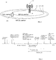
- Fig. 1 illustrates a wireless communication network 10 according to the NR standard currently being developed by Third Generation Partnership Project (3GPP).
- the wireless communication network 10 comprises one or more base stations 100 providing service to user equipment (UEs) 200 in a cell 20 of the wireless communication network 10.
- the base stations 100 in the wireless communication network 10 are also referred to as Evolved NodesBs (eNBs) and gNodeBs (gNBs) in 3GPP standards.
- eNBs Evolved NodesBs
- gNodeBs gNodeBs
- the UEs 200 may comprise cellular telephones, smart phones, laptop computers, notebook computers, tablets, machine-to-machine (M2M) devices (also known as machine type communication (MTC) devices), or other types of wireless end user devices capable of communicating over wireless communication networks 10.
- M2M machine-to-machine
- MTC machine type communication
- Fig. 1 further illustrates the cell 20 having different coverages of each a NR downlink carrier 210, of a primary or NR UL carrier 220 and of a supplementary uplink (SUL) carrier 230 such that the NR cell has a SUL carrier and a NR UL carrier in uplink.
- the SUL carrier may be a relatively low frequency carrier which can be shared (in time and/or frequency domain) with other RAT systems such as LTE.
- Fig. 1 exemplarily depicts different coverages of the NR UL carrier, the SUL carrier and the NR DL carrier associated to the NR cell, wherein the NR UL carrier and SUL may be paired resulting in a NR frequency combination.
- a UE 200 may declare or trigger a radio link failure, RLF when it loses the synchronization with the network. As a result, the UE may release network resources and any ongoing services is interrupted.
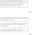
- UE 200 performs the following steps:
- Separately monitoring may mean to monitor failure events or retransmissions for each of the plurality of carriers; e.g. using separate RLF counters, and/or separately counting the retransmissions for each of the plurality of carriers. Separately monitoring may further include separately for each carrier determining that a certain threshold number of retransmissions is reached or passed. The certain thresholds may be different for each carrier.
- the base station, gNB may perform the following corresponding step as illustrated by Fig. 5 : S51: receiving an information of a failure of RLC data packet transmissions with respect to one of the UL carriers.
- Said failure has been determined by the UE by monitoring retransmissions of radio link control, RLC, data packets separately for at least two of the plurality of UL carriers.
- the primary carrier is a NR UL carrier and the supplementary carrier is a supplementary UL, SUL carrier
- the UE may determine a corresponding carrier RLF, e.g. a NR RLF and/or a SUL RLF.
- a carrier RLF e.g. a NR RLF and/or a SUL RLF.
- UE 200 may comprise functions being classified according to different layers.
- UE 200 may comprise a RLC entity for performing RLC functions, and an RRC entity for performing RRC functions.
- the RLC entity monitors RLC retransmission failures separately for a plurality of carriers e.g. a primary carrier and a supplementary carrier.
- the RLC entity If a transmission failure is detected on one of the plurality of carriers, the RLC entity provides an indication indicative of the RLC transmission failure and the carrier where the transmission failure has occurred to the RRC entity. The RRC entity then determines a RLF of the corresponding carrier.
- a RLC transmission failure for a carrier is assumed, if a given maximum number of RLC retransmissions for a RLC data packet (RLC AM PDU) has been reached (or exceeded) for such carrier. Consequently, the RLC entity may send a report indicative of an RLC transmission failure and the corresponding carrier to the RRC layer.
- a carrier e.g. primary or supplementary carrier
- the given maximum number may be similar for the different carriers or may be different e.g. for the NR UL carrier and the SUL.
- the network e.g. the gNB, may configure different RLC configurations for the different carriers, e.g. for the SUL carrier and the NR carrier.
- different maximum numbers of RLC retransmissions for triggering of RLF failure can be configured for SUL carrier and NR carrier.
- NR UL carrier may be deployed at a higher carrier frequency than that for SUL carrier, meaning that NR UL carrier may be associated with higher sub-carrier spacing (i.e., shorter slot duration)
- a higher maximum number of RLC retransmissions may be configured for NR UL carrier, while a lower maximum number of RLC retransmissions for SUL carrier. In this way, unnecessary RLF events may be avoided.
- a common RLC configuration for both the SUL carrier and the NR carrier with a common counter for RLC retransmissions for both carrier is provided.
- RLC AM PDU For the same RLC data packet (RLC AM PDU), there may be a portion of the RLC retransmissions carried on NR UL carrier while the rest of RLC retransmissions are carried in SUL carrier.
- the RLC entity may sends a report to the RRC layer, indicating that the maximum RLC retransmissions has been reached without sending an indicator of any carrier.
- Fig. 6 illustrates exemplary steps performed by the UE 200:
- Commonly monitoring may mean to monitor failure events or retransmissions together for the plurality of carriers; e.g. using one single RLF counter for all the carriers, and/or counting the failures together for all of the plurality of carriers. Commonly monitoring may further include determining that a certain threshold number of retransmissions for all the carriers together is reached or passed.
- Fig. 7 shows a corresponding exemplary step performed in the base station
- gNB 100 S71: receiving from the UE 200 an information indicative of a common RLF, wherein a common RLF is resulting from performing retransmissions at the UE of a certain RLC data packet on at least two of the plurality of UL carriers being commonly monitored for both UL carriers.
- the gNB may configure the UE how to count RLC retransmissions on the different carriers.
- the UE may be configured such that the UE RLC only counts RLC retransmissions on one specific carrier (e.g. NR UL carrier or SUL) for reporting an RLC transmission failure.
- one specific carrier e.g. NR UL carrier or SUL
- the UE may be configured such that the UE RLC counts RLC retransmissions on all carriers for reporting an RLC transmission failure.
- the UE may take one of the following actions: If the SUL carrier is configured and active, the UE triggers a scheduling request, SR, transmission on the SUL carrier indicating that the UE is preferring to switch to the SUL carrier for UL data transfer. This action may only be performed, if the DL channel quality (such as RSRP) is below a given threshold.
- SR scheduling request
- the UE may trigger an access to a random-access channel, RACH (that is a shared channel used by wireless terminals to access the mobile network) on the SUL carrier indicating that the data (RLC) transmissions don't get through on the NR carrier.
- RACH random-access channel
- the network In response to receiving an indication about an RLF failure of one carrier (e.g. the NR UL carrier) the network (gNB) can take proper actions.
- the gNB may order the UE to switch to another carrier (e.g. to the SUL carrier) for the PUSCH transmission.
- PUCCH-SR resources may be configured for the corresponding LCHs accordingly.
- the gNB may further configure the existing SUL carrier to be active, or may reconfigure the UE with another active SUL carrier if the existing SUL is inactive.
- the UE e.g. the UE media access, MAC, entity
- the signaling be performed by means of RRC, MAC CE, and/or any other layer1/layer2 signaling means.
- the UE may take one of the following actions to recover from the failure:
- the UE first performs a cell search to determine the best cell for radio link re-establishment.
- the UE may select a prepared cell, which may be the same cell, a different cell from the same gNB, or a prepared cell from a different gNB, wherein the activity can be resumed (the UE staying in connected mode) via radio connection re-establishment procedure since the previous UE context can be achieved by inter-cell communication.
- the UE may determine the best cell based a configuration by the network. Therein, The UE may be configured to:
- the network may configure the UE, if a RLF is triggered due to RLC retransmission failures (e.g. if the RLC retransmissions for a RLC AM PDU reaches a configured threshold) on a specific UL carrier, or on all UL carriers belonging to the same cell.
- RLC retransmission failures e.g. if the RLC retransmissions for a RLC AM PDU reaches a configured threshold
- the same or similar recovery actions as described before may applied.
- the UE upon triggering of RLF, if there is no prepared cell available for radio connection re-establishment, the UE leaves the RRC connected state, and enters the RRC Idle state. The UE may then select the best cell which is not prepared. The selection of best cell may be performed as described above.
- a random access, RA, procedure for radio connection re-establishment for a UE is determined to a NR cell with SUL carrier
- one of the following rules or policies can be configured by the network for such procedure:
- the configuration for radio link maintenance at RLF can be configured via UE specific RRC signaling or broadcasting SIB.
- a UE RLC entity shall report which carrier, of a SUL carrier and the NR UL carrier where the maximum RLC retransmission attempts have been reached.
- the base station may configure different RLC configurations for SUL carrier and NR carrier, wherein, different maximum number of RLC retransmissions for triggering of RLF failure can be configured for SUL carrier and NR carrier.
- the NR UL carrier is deployed at a higher carrier frequency than that for SUL carrier, meaning that NR UL carrier may be associated with higher sub-carrier spacing (i.e., shorter slot duration); thus, a higher maximum number of RLC retransmissions may be configured for NR UL carrier, while a lower maximum number of RLC retransmissions for SUL carrier may be configured. In such way, unnecessary RLF events may be avoided.
- a third embodiment it may be assumed that there is only one RLC configuration for both SUL carrier and NR carrier. There may be a common counter for RLC retransmissions for both carriers. For the same RLC AM PDU, there may be a portion of the RLC retransmissions carried on NR UL carrier while the rest of RLC retransmissions are carried in SUL carrier. In this case, when the maximum number of RLC retransmissions for a RLC AM PDU has been reached, the RLC entity sends a report to RRC, indicating that the maximum RLC retransmissions has been reached, the carrier indicators may not be present in the report.
- the base station may configure the UE to determine on which carriers to count RLC retransmissions.
- the UE RLC may only count RLC retransmissions on one specific carrier for RLF trigger.
- the UE RLC may count RLC retransmissions on all carriers for RLF trigger.
- the RLC entity may need to be aware of the carrier on which every PUSCH transmission is transmitted, such knowledge may be informed to higher layers by the physical, PHY, layer.
- the next embodiments concern different option of UE actions upon detection of RLF events that are described in above sections (radio connection maintenance).
- the UE may take one or a plurality of actions as follows:
- the UE may take one or a plurality of actions as follows to recover from the failure:
- the network may configure the UE if RLF is triggered due to RLC retransmission failures (i.e., the RLC retransmissions for a RLC AM PDU reaches a given threshold which can be configured) on a specific UL carrier, or on all UL carriers belonging to the same cell.
- RLC retransmission failures i.e., the RLC retransmissions for a RLC AM PDU reaches a given threshold which can be configured
- the UE upon triggering of RLF, if there is no any prepared cell available for radio connection re-establishment, the UE leaves RRC connected state, and stays at RRC Idle state, the UE selects best cell which is not prepared. The selection of best cell applies the same means as that in the sixth embodiment.
- a RA procedure for radio connection re-establishment for a UE is determined to a NR cell with SUL carrier
- one of the following policy can be configured by the network for RA procedure:
- the specific configuration for radio link maintenance at RLF can be configured via UE specific RRC signaling or broadcasting SIB.
- Fig. 6 illustrates UE 200 in accordance with one or more embodiments.
- UE 200 comprises an antenna or antenna array 210 having multiple antennas 215, a transceiver 220 for communicating with the base station, UE processing circuity 230 e.g. for performing the steps depicted in any of Figs. 2 and 4 and a UE memory 240 for storing corresponding instructions to performed by the UE processing circuitry 240.
- Fig. 7 illustrates base station or gNB 100 in accordance with one or more embodiments.
- Base station 100 comprises an antenna or an antenna array 110 having multiple antennas 115, a transceiver 120 for communicating with the UE, base station processing circuity 130 e.g. for performing the steps depicted in any of Figs. 1 and 3 and a base station memory 140 for storing corresponding instructions to performed by the base station processing circuitry 140.
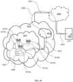
- a communication system includes a telecommunication network 3210, such as a 3GPP-type cellular network, which comprises an access network 3211, such as a radio access network, and a core network 3214.
- the access network 3211 comprises a plurality of base stations 3212a, 3212b, 3212c, such as NBs, eNBs, gNBs or other types of wireless access points, each defining a corresponding coverage area 3213a, 3213b, 3213c.
- Each base station 3212a, 3212b, 3212c is connectable to the core network 3214 over a wired or wireless connection 3215.
- a first user equipment (UE) 3291 located in coverage area 3213c is configured to wirelessly connect to, or be paged by, the corresponding base station 3212c.
- a second UE 3292 in coverage area 3213a is wirelessly connectable to the corresponding base station 3212a. While a plurality of UEs 3291, 3292 are illustrated in this example, the disclosed embodiments are equally applicable to a situation where a sole UE is in the coverage area or where a sole UE is connecting to the corresponding base station 3212.
- the telecommunication network 3210 is itself connected to a host computer 3230, which may be embodied in the hardware and/or software of a standalone server, a cloud-implemented server, a distributed server or as processing resources in a server farm.
- the host computer 3230 may be under the ownership or control of a service provider, or may be operated by the service provider or on behalf of the service provider.
- the connections 3221, 3222 between the telecommunication network 3210 and the host computer 3230 may extend directly from the core network 3214 to the host computer 3230 or may go via an optional intermediate network 3220.
- the intermediate network 3220 may be one of, or a combination of more than one of, a public, private or hosted network; the intermediate network 3220, if any, may be a backbone network or the Internet; in particular, the intermediate network 3220 may comprise two or more sub-networks (not shown).
- the communication system of Fig. 10 as a whole enables connectivity between one of the connected UEs 3291, 3292 and the host computer 3230.
- the connectivity may be described as an over-the-top (OTT) connection 3250.
- the host computer 3230 and the connected UEs 3291, 3292 are configured to communicate data and/or signaling via the OTT connection 3250, using the access network 3211, the core network 3214, any intermediate network 3220 and possible further infrastructure (not shown) as intermediaries.
- the OTT connection 3250 may be transparent in the sense that the participating communication devices through which the OTT connection 3250 passes are unaware of routing of uplink and downlink communications.
- a base station 3212 may not or need not be informed about the past routing of an incoming downlink communication with data originating from a host computer 3230 to be forwarded (e.g., handed over) to a connected UE 3291. Similarly, the base station 3212 need not be aware of the future routing of an outgoing uplink communication originating from the UE 3291 towards the host computer 3230.
- a host computer 3310 comprises hardware 3315 including a communication interface 3316 configured to set up and maintain a wired or wireless connection with an interface of a different communication device of the communication system 3300.
- the host computer 3310 further comprises processing circuitry 3318, which may have storage and/or processing capabilities.
- the processing circuitry 3318 may comprise one or more programmable processors, application-specific integrated circuits, field programmable gate arrays or combinations of these (not shown) adapted to execute instructions.
- the host computer 3310 further comprises software 3311, which is stored in or accessible by the host computer 3310 and executable by the processing circuitry 3318.
- the software 3311 includes a host application 3312.
- the host application 3312 may be operable to provide a service to a remote user, such as a UE 3330 connecting via an OTT connection 3350 terminating at the UE 3330 and the host computer 3310. In providing the service to the remote user, the host application 3312 may provide user data which is transmitted using the OTT connection 3350.
- the communication system 3300 further includes a base station 3320 provided in a telecommunication system and comprising hardware 3325 enabling it to communicate with the host computer 3310 and with the UE 3330.
- the hardware 3325 may include a communication interface 3326 for setting up and maintaining a wired or wireless connection with an interface of a different communication device of the communication system 3300, as well as a radio interface 3327 for setting up and maintaining at least a wireless connection 3370 with a UE 3330 located in a coverage area (not shown in Fig. 11 ) served by the base station 3320.
- the communication interface 3326 may be configured to facilitate a connection 3360 to the host computer 3310.
- the connection 3360 may be direct or it may pass through a core network (not shown in Fig.
- the hardware 3325 of the base station 3320 further includes processing circuitry 3328, which may comprise one or more programmable processors, application-specific integrated circuits, field programmable gate arrays or combinations of these (not shown) adapted to execute instructions.
- the base station 3320 further has software 3321 stored internally or accessible via an external connection.
- the communication system 3300 further includes the UE 3330 already referred to.
- Its hardware 3335 may include a radio interface 3337 configured to set up and maintain a wireless connection 3370 with a base station serving a coverage area in which the UE 3330 is currently located.
- the hardware 3335 of the UE 3330 further includes processing circuitry 3338, which may comprise one or more programmable processors, application-specific integrated circuits, field programmable gate arrays or combinations of these (not shown) adapted to execute instructions.
- the UE 3330 further comprises software 3331, which is stored in or accessible by the UE 3330 and executable by the processing circuitry 3338.
- the software 3331 includes a client application 3332.
- the client application 3332 may be operable to provide a service to a human or non-human user via the UE 3330, with the support of the host computer 3310.
- an executing host application 3312 may communicate with the executing client application 3332 via the OTT connection 3350 terminating at the UE 3330 and the host computer 3310.
- the client application 3332 may receive request data from the host application 3312 and provide user data in response to the request data.
- the OTT connection 3350 may transfer both the request data and the user data.
- the client application 3332 may interact with the user to generate the user data that it provides.
- the host computer 3310, base station 3320 and UE 3330 illustrated in Fig. 11 may be identical to the host computer 3230, one of the base stations 3212a, 3212b, 3212c and one of the UEs 3291, 3292 of Fig. 10 , respectively.
- the inner workings of these entities may be as shown in Fig. 11 and independently, the surrounding network topology may be that of Fig. 10 .
- the OTT connection 3350 has been drawn abstractly to illustrate the communication between the host computer 3310 and the use equipment 3330 via the base station 3320, without explicit reference to any intermediary devices and the precise routing of messages via these devices.
- Network infrastructure may determine the routing, which it may be configured to hide from the UE 3330 or from the service provider operating the host computer 3310, or both. While the OTT connection 3350 is active, the network infrastructure may further take decisions by which it dynamically changes the routing (e.g., on the basis of load balancing consideration or reconfiguration of the network).
- the wireless connection 3370 between the UE 3330 and the base station 3320 is in accordance with the teachings of the embodiments described throughout this disclosure.
- One or more of the various embodiments improve the performance of OTT services provided to the UE 3330 using the OTT connection 3350, in which the wireless connection 3370 forms the last segment. More precisely, the teachings of these embodiments may improve the latency or power consumption and thereby provide benefits such as better responsiveness, extended battery lifetime.
- a measurement procedure may be provided for the purpose of monitoring data rate, latency and other factors on which the one or more embodiments improve.
- the measurement procedure and/or the network functionality for reconfiguring the OTT connection 3350 may be implemented in the software 3311 of the host computer 3310 or in the software 3331 of the UE 3330, or both.
- sensors (not shown) may be deployed in or in association with communication devices through which the OTT connection 3350 passes; the sensors may participate in the measurement procedure by supplying values of the monitored quantities exemplified above, or supplying values of other physical quantities from which software 3311, 3331 may compute or estimate the monitored quantities.
- the reconfiguring of the OTT connection 3350 may include message format, retransmission settings, preferred routing etc.; the reconfiguring need not affect the base station 3320, and it may be unknown or imperceptible to the base station 3320. Such procedures and functionalities may be known and practiced in the art.
- measurements may involve proprietary UE signaling facilitating the host computer's 3310 measurements of throughput, propagation times, latency and the like.
- the measurements may be implemented in that the software 3311, 3331 causes messages to be transmitted, in particular empty or 'dummy' messages, using the OTT connection 3350 while it monitors propagation times, errors etc.
- Fig. 12 is a flowchart illustrating a method implemented in a communication system, in accordance with one embodiment.
- the communication system includes a host computer, a base station and a UE which may be those described with reference to Figures 32 and 33. For simplicity of the present disclosure, only drawing references to Fig. 12 will be included in this section.
- the host computer provides user data.
- the host computer provides the user data by executing a host application.
- the host computer initiates a transmission carrying the user data to the UE.
- the base station transmits to the UE the user data which was carried in the transmission that the host computer initiated, in accordance with the teachings of the embodiments described throughout this disclosure.
- the UE executes a client application associated with the host application executed by the host computer.
- Fig. 13 is a flowchart illustrating a method implemented in a communication system, in accordance with one embodiment.
- the communication system includes a host computer, a base station and a UE which may be those described with reference to Figures 32 and 33. For simplicity of the present disclosure, only drawing references to Figure 35 will be included in this section.
- the host computer provides user data.
- the host computer provides the user data by executing a host application.
- the host computer initiates a transmission carrying the user data to the UE. The transmission may pass via the base station, in accordance with the teachings of the embodiments described throughout this disclosure.
- the UE receives the user data carried in the transmission.
- Fig. 14 is a flowchart illustrating a method implemented in a communication system, in accordance with one embodiment.
- the communication system includes a host computer, a base station and a UE which may be those described with reference to Figures 32 and 33. For simplicity of the present disclosure, only drawing references to Figure 36 will be included in this section.
- the UE receives input data provided by the host computer.
- the UE provides user data.
- the UE provides the user data by executing a client application.
- the UE executes a client application which provides the user data in reaction to the received input data provided by the host computer.
- the executed client application may further consider user input received from the user.
- the UE initiates, in an optional third substep 3630, transmission of the user data to the host computer.
- the host computer receives the user data transmitted from the UE, in accordance with the teachings of the embodiments described throughout this disclosure.
- Fig. 15 is a flowchart illustrating a method implemented in a communication system, in accordance with one embodiment.
- the communication system includes a host computer, a base station and a UE which may be those described with reference to Figures 32 and 33. For simplicity of the present disclosure, only drawing references to Figure 37 will be included in this section.
- the base station receives user data from the UE.
- the base station initiates transmission of the received user data to the host computer.
- the host computer receives the user data carried in the transmission initiated by the base station.
Landscapes
- Engineering & Computer Science (AREA)
- Signal Processing (AREA)
- Computer Networks & Wireless Communication (AREA)
- Mobile Radio Communication Systems (AREA)
- Detection And Prevention Of Errors In Transmission (AREA)
Claims (9)
- Procédé dans un équipement utilisateur, UE (200), pour gérer des défaillances de liaison radio, RLF, dans lequel l'UE est connecté à un réseau de communications radio au moyen d'une pluralité de porteuses de liaison montante, UL, (220, 230), comprenant les étapes consistant à :- surveiller (S41) des retransmissions de commande de liaison radio, RLC, de paquets de données pour chacune d'une pluralité de porteuses UL,- déterminer (S42) une défaillance de transmissions de paquets de données RLC par rapport à l'une des porteuses UL, et- fournir (S43) une information indicative de la défaillance de ladite porteuse UL,dans lequel la défaillance de transmissions de paquets de données RLC pour ladite porteuse est déterminée, si un certain nombre maximum de retransmissions RLC pour un paquet de données RLC a été atteint pour cette porteuse,caractérisé en ce que chacune de la pluralité de porteuses est associée à un nombre maximum de retransmissions RLC pour un paquet de données RLC,si bien qu'un premier nombre maximum est associé à la porteuse UL primaire (220), et qu'un deuxième nombre maximum est associé à une porteuse UL, SUL supplémentaire (230), dans lequel le premier nombre maximum est différent du deuxième nombre maximum.
- Procédé selon la revendication précédente, dans lequel la porteuse UL primaire est une nouvelle porteuse radio, NR, UL.
- Procédé selon l'une quelconque des revendications précédentes, dans lequel l'UE transmet une information indiquant la défaillance, RLF, et la porteuse UL affectée par la RLF au réseau de communications radio.
- Procédé selon l'une quelconque des revendications précédentes, dans lequel l'UE reçoit une configuration du premier nombre maximum et du deuxième nombre maximum pour déterminer des défaillances de liaison radio respectivement de la porteuse UL primaire et de la porteuse SUL.
- Procédé selon l'une quelconque des revendications précédentes, dans lequel l'UE (200) comprend une entité RLC pour exécuter des fonctions RLC, et une entité RRC pour exécuter des fonctions RRC, dans lequel l'entité RLC exécute les étapes de surveillance de retransmissions de paquets de données RLC séparément pour une pluralité de porteuses UL, et déterminer une défaillance de transmissions de paquets de données RLC par rapport à l'une des porteuses UL, et fournit les informations indicatives de la défaillance de ladite porteuse UL à l'entité RRC.
- Procédé selon la revendication précédente, dans lequel l'entité RRC exécute le déclenchement d'une défaillance de liaison radio, RLF au niveau du réseau de communications radio.
- Procédé dans une station de base d'un réseau de communications radio, gNB (100), pour gérer des défaillances de liaison radio, RLF,
dans lequel un UE (200) est connecté au gNB au moyen d'une pluralité de porteuses de liaison montante, UL, comprenant :- la réception (S51) d'une information d'une défaillance de transmissions de paquets de données RLC par rapport à l'une des porteuses UL, ladite défaillance ayant été déterminée en surveillant des retransmissions de commande de liaison radio, RLC, de paquets de données pour chacune d'au moins deux de la pluralité de porteuses UL,- le procédé comprenant en outre l'envoi d'une configuration à l'UE indiquant un nombre maximum de retransmissions RLC pour un paquet de données RLC pour déterminer la défaillance de transmissions de paquets de données RLC pour ladite porteuse,- caractérisé en ce que la configuration comprend un premier nombre maximum associé à la porteuse UL primaire (220), et un deuxième nombre maximum associé à la porteuse UL, SUL supplémentaire (230), dans lequel le premier nombre maximum est différent du deuxième nombre maximum. - Equipement utilisateur, UE, (200), étant adapté pour mettre en œuvre les procédés selon l'une quelconque des revendications 1 à 6.
- Station de base d'un réseau de communications radio, gNB (100), étant adapté pour mettre en œuvre le procédé selon la revendication 7.
Applications Claiming Priority (2)
| Application Number | Priority Date | Filing Date | Title |
|---|---|---|---|
| US201862616194P | 2018-01-11 | 2018-01-11 | |
| PCT/EP2019/050716 WO2019138087A1 (fr) | 2018-01-11 | 2019-01-11 | Maintenance de liaison radio impliquant de multiples porteuses de liaison montante |
Publications (2)
| Publication Number | Publication Date |
|---|---|
| EP3738246A1 EP3738246A1 (fr) | 2020-11-18 |
| EP3738246B1 true EP3738246B1 (fr) | 2023-03-08 |
Family
ID=65019528
Family Applications (1)
| Application Number | Title | Priority Date | Filing Date |
|---|---|---|---|
| EP19700495.5A Active EP3738246B1 (fr) | 2018-01-11 | 2019-01-11 | Maintenance de liaison radio impliquant de multiples porteuses de liaison montante |
Country Status (8)
| Country | Link |
|---|---|
| US (1) | US12010750B2 (fr) |
| EP (1) | EP3738246B1 (fr) |
| JP (1) | JP7132336B2 (fr) |
| CN (1) | CN111886824B (fr) |
| BR (1) | BR112020013936A2 (fr) |
| PH (1) | PH12020500580A1 (fr) |
| RU (1) | RU2741582C1 (fr) |
| WO (1) | WO2019138087A1 (fr) |
Families Citing this family (4)
| Publication number | Priority date | Publication date | Assignee | Title |
|---|---|---|---|---|
| US11082329B2 (en) * | 2018-05-31 | 2021-08-03 | At&T Intellectual Property I, L.P. | Lossless data delivery at route changes in wireless radio networks |
| KR20210098128A (ko) | 2020-01-31 | 2021-08-10 | 삼성전자주식회사 | 무선 통신 시스템에서 사이드링크 보조 캐리어를 제어하는 장치 및 방법 |
| CN114679243A (zh) * | 2020-12-24 | 2022-06-28 | 中国移动通信有限公司研究院 | 数据传输方法及装置 |
| CN120345341A (zh) * | 2023-06-30 | 2025-07-18 | 上海传英信息技术有限公司 | 无线资源控制恢复方法、通信设备及存储介质 |
Family Cites Families (32)
| Publication number | Priority date | Publication date | Assignee | Title |
|---|---|---|---|---|
| BRPI0910851B1 (pt) * | 2008-04-21 | 2021-05-25 | Apple Inc | Método para um processo de harq |
| JP5161375B2 (ja) * | 2009-01-30 | 2013-03-13 | インターデイジタル パテント ホールディングス インコーポレイテッド | 物理個別チャネル確立および監視手順を実行するための方法および装置 |
| WO2011100673A1 (fr) | 2010-02-12 | 2011-08-18 | Interdigital Patent Holdings, Inc. | Procédé et appareil pour améliorer l'efficacité pour utilisateurs en bord de cellule et signaler des conditions de défaillance de liaison radio par porteuses composantes coopératives de liaison descendante |
| KR101457754B1 (ko) * | 2009-03-12 | 2014-11-03 | 인터디지탈 패튼 홀딩스, 인크 | 무선 링크 실패에 대한 모니터링을 위한 방법 및 장치 |
| CN102845122B9 (zh) * | 2009-09-25 | 2016-06-29 | 黑莓有限公司 | 用于多载波网络操作的系统和方法 |
| US8804632B2 (en) * | 2009-10-30 | 2014-08-12 | Lg Electronics Inc. | Method of performing random access procedure in multiple component carrier system |
| US20120281527A1 (en) * | 2010-01-05 | 2012-11-08 | Benoist Pierre Sebire | Re-Establishment of Component Carriers in a Wireless Communication System |
| US9232418B2 (en) * | 2011-04-15 | 2016-01-05 | Telefonaktiebolaget L M Ericsson (Publ) | Methods and devices for radio link monitoring |
| US9042315B2 (en) | 2011-05-03 | 2015-05-26 | Mediatek Inc. | SCELL radio link monitoring and radio link failure handling |
| WO2013045537A1 (fr) * | 2011-09-30 | 2013-04-04 | Nokia Siemens Networks Oy | Filtrage de rapport de panne de liaison hertzienne |
| US9854495B2 (en) * | 2013-01-11 | 2017-12-26 | Lg Electronics Inc. | Radio link failure reporting in a system using multiple cells |
| ES2628296T3 (es) * | 2013-01-18 | 2017-08-02 | Telefonaktiebolaget L M Ericsson (Publ) | Adaptación de una red móvil |
| WO2014117854A1 (fr) * | 2013-02-01 | 2014-08-07 | Nokia Solutions And Networks Oy | Gestion d'une défaillance de liaison radio dans les télécommunications |
| EP3429258B1 (fr) | 2013-02-14 | 2020-04-08 | LG Electronics Inc. | Procédé permettant de rapporter des informations mbms dans un système de communication sans fil et dispositif de support associé |
| KR102037389B1 (ko) * | 2013-04-05 | 2019-10-28 | 주식회사 팬택 | 이중 연결성을 지원하는 무선 통신 시스템에서 무선링크 제어 방법 및 그 장치 |
| CN104105364B (zh) | 2013-04-07 | 2017-04-05 | 华为技术有限公司 | 机柜及具有该机柜的机柜组 |
| CN104685930B (zh) | 2013-04-09 | 2019-02-19 | 华为技术有限公司 | 一种通讯方法和终端 |
| WO2015008962A1 (fr) * | 2013-07-17 | 2015-01-22 | Lg Electronics Inc. | Procédé de rapport de défaillance de retransmission de commande de liaison radio et dispositif associé |
| US20150133122A1 (en) | 2013-11-08 | 2015-05-14 | Industrial Technology Research Institute | Method of Handling Radio Link Failure |
| KR20150055535A (ko) * | 2013-11-11 | 2015-05-21 | 한국전자통신연구원 | 단말이 복수의 기지국에 이중으로 연결될 수 있는 네트워크 환경에서의 통신 방법 및 장치 |
| US9838945B2 (en) * | 2014-04-14 | 2017-12-05 | Htc Corporation | Method of handling link failure and related communication device |
| US9894702B2 (en) * | 2015-05-14 | 2018-02-13 | Intel IP Corporation | Performing primary cell functions in a secondary cell |
| US9906332B2 (en) * | 2015-05-29 | 2018-02-27 | Apple Inc. | Radio link control recovery based on medium access feedback |
| WO2017078090A1 (fr) * | 2015-11-05 | 2017-05-11 | 株式会社Nttドコモ | Dispositif utilisateur et procédé de communication par radio |
| WO2018062845A1 (fr) * | 2016-09-27 | 2018-04-05 | 엘지전자 주식회사 | Procédé permettant le fonctionnement d'un équipement utilisateur dans un système de communication sans fil et dispositif pour la mise en oeuvre du procédé |
| US11117274B2 (en) * | 2016-11-01 | 2021-09-14 | Outdoor Element, Llc | Knife with fire starting implement |
| US10484931B2 (en) * | 2016-12-23 | 2019-11-19 | Ofinno, Llc | Licensed assisted access radio link failure |
| KR102339471B1 (ko) * | 2017-05-04 | 2021-12-15 | 광동 오포 모바일 텔레커뮤니케이션즈 코포레이션 리미티드 | 리포트 송신 방법, 리포트 수신 방법, 장치 및 시스템 |
| EP3661316B1 (fr) * | 2017-07-24 | 2021-09-08 | Guangdong Oppo Mobile Telecommunications Corp., Ltd. | Procédé de traitement d'échec de liaison radio et dispositif terminal |
| CN107567041B (zh) * | 2017-08-08 | 2019-12-10 | 电信科学技术研究院 | 一种处理无线链路故障的方法和设备 |
| US10750562B2 (en) * | 2018-02-02 | 2020-08-18 | Ofinno, Llc | Connection failure report considering bandwidth |
| WO2019215342A1 (fr) * | 2018-05-11 | 2019-11-14 | Telefonaktiebolaget Lm Ericsson (Publ) | Procédure de surveillance de liaison radio (rlm) pour un dispositif sans fil conçu pour fonctionner en utilisant des premier et deuxième modes de fonctionnement dans un temps de chevauchement dans une première cellule |
-
2019
- 2019-01-11 EP EP19700495.5A patent/EP3738246B1/fr active Active
- 2019-01-11 CN CN201980018780.3A patent/CN111886824B/zh active Active
- 2019-01-11 JP JP2020538048A patent/JP7132336B2/ja not_active Expired - Fee Related
- 2019-01-11 BR BR112020013936-0A patent/BR112020013936A2/pt not_active IP Right Cessation
- 2019-01-11 RU RU2020126660A patent/RU2741582C1/ru active
- 2019-01-11 US US16/959,270 patent/US12010750B2/en active Active
- 2019-01-11 WO PCT/EP2019/050716 patent/WO2019138087A1/fr not_active Ceased
-
2020
- 2020-07-02 PH PH12020500580A patent/PH12020500580A1/en unknown
Also Published As
| Publication number | Publication date |
|---|---|
| EP3738246A1 (fr) | 2020-11-18 |
| US20200337102A1 (en) | 2020-10-22 |
| JP2021510477A (ja) | 2021-04-22 |
| CN111886824B (zh) | 2026-08-07 |
| JP7132336B2 (ja) | 2022-09-06 |
| RU2741582C1 (ru) | 2021-01-27 |
| BR112020013936A2 (pt) | 2020-12-01 |
| PH12020500580A1 (en) | 2021-05-17 |
| US12010750B2 (en) | 2024-06-11 |
| WO2019138087A1 (fr) | 2019-07-18 |
| CN111886824A (zh) | 2020-11-03 |
Similar Documents
| Publication | Publication Date | Title |
|---|---|---|
| US11838747B2 (en) | Uplink congestion control based on sip messaging | |
| CN114747288B (zh) | 报告无线网络中的先听后说失败 | |
| KR102335619B1 (ko) | 무선 통신 네트워크에서의 사용자 장비, 네트워크 노드, 및 방법들 | |
| US11895548B2 (en) | Link management for a connected user equipment | |
| US20220286890A1 (en) | Method for constructing logged measurement entry and device supporting the same | |
| US11696355B2 (en) | System and method for indicating coverage types for user devices in dual connectivity wireless networks | |
| KR101780609B1 (ko) | 사용자 장비 및 프로토콜 및 디바이스 대 디바이스 통신을 위한 방법 | |
| CN102754469B (zh) | 在无线通信系统中报告记录的测量的装置和方法 | |
| CN103384382B (zh) | 无线链路管理的方法、用户设备和基站 | |
| CN110892781A (zh) | 新增次节点的方法及相关装置 | |
| US11528626B2 (en) | Radio link monitoring (RLM) procedure for a wireless device configured to operate using first and second operational modes within an overlapping time in a first cell | |
| US20240414796A1 (en) | Special Cell Dormancy for New Radio | |
| US12156249B2 (en) | Method and apparatus for channel occupancy measurement | |
| US12069605B2 (en) | First wireless device, first network node, second wireless device, and methods performed thereby, for determining a status of a cell | |
| CN103026750A (zh) | 在无线通信系统中报告所记录的测量的装置和方法 | |
| US12010750B2 (en) | Radio link maintenance involving multiple uplink carriers | |
| JP2021503800A (ja) | 高速セルアクセスのための測定 | |
| WO2014113919A1 (fr) | Gestion d'une défaillance de communication dans plusieurs systèmes de connexion | |
| CN115362717B (zh) | 路径损耗参考信号管理 | |
| EP3949520B1 (fr) | Interdiction de contrôle d'accès fondée sur une qualité de cellule | |
| US12219640B2 (en) | Managing sidelink and non-sidelink information | |
| WO2024033006A1 (fr) | Gestion de capacité d'agrégation de porteuses dans une opération de module d'identité d'abonné universel multiple (usim) | |
| US12096294B2 (en) | Mutually exclusive configurations |
Legal Events
| Date | Code | Title | Description |
|---|---|---|---|
| STAA | Information on the status of an ep patent application or granted ep patent |
Free format text: STATUS: UNKNOWN |
|
| STAA | Information on the status of an ep patent application or granted ep patent |
Free format text: STATUS: THE INTERNATIONAL PUBLICATION HAS BEEN MADE |
|
| PUAI | Public reference made under article 153(3) epc to a published international application that has entered the european phase |
Free format text: ORIGINAL CODE: 0009012 |
|
| STAA | Information on the status of an ep patent application or granted ep patent |
Free format text: STATUS: REQUEST FOR EXAMINATION WAS MADE |
|
| 17P | Request for examination filed |
Effective date: 20200811 |
|
| AK | Designated contracting states |
Kind code of ref document: A1 Designated state(s): AL AT BE BG CH CY CZ DE DK EE ES FI FR GB GR HR HU IE IS IT LI LT LU LV MC MK MT NL NO PL PT RO RS SE SI SK SM TR |
|
| AX | Request for extension of the european patent |
Extension state: BA ME |
|
| DAV | Request for validation of the european patent (deleted) | ||
| DAX | Request for extension of the european patent (deleted) | ||
| REG | Reference to a national code |
Ref country code: DE Ref legal event code: R079 Ref document number: 602019026121 Country of ref document: DE Free format text: PREVIOUS MAIN CLASS: H04L0001180000 Ipc: H04L0005000000 |
|
| RIC1 | Information provided on ipc code assigned before grant |
Ipc: H04W 36/30 20090101ALI20220728BHEP Ipc: H04L 1/18 20060101ALI20220728BHEP Ipc: H04W 76/18 20180101ALI20220728BHEP Ipc: H04W 36/00 20090101ALI20220728BHEP Ipc: H04L 5/00 20060101AFI20220728BHEP |
|
| GRAP | Despatch of communication of intention to grant a patent |
Free format text: ORIGINAL CODE: EPIDOSNIGR1 |
|
| STAA | Information on the status of an ep patent application or granted ep patent |
Free format text: STATUS: GRANT OF PATENT IS INTENDED |
|
| INTG | Intention to grant announced |
Effective date: 20221115 |
|
| GRAS | Grant fee paid |
Free format text: ORIGINAL CODE: EPIDOSNIGR3 |
|
| GRAA | (expected) grant |
Free format text: ORIGINAL CODE: 0009210 |
|
| STAA | Information on the status of an ep patent application or granted ep patent |
Free format text: STATUS: THE PATENT HAS BEEN GRANTED |
|
| AK | Designated contracting states |
Kind code of ref document: B1 Designated state(s): AL AT BE BG CH CY CZ DE DK EE ES FI FR GB GR HR HU IE IS IT LI LT LU LV MC MK MT NL NO PL PT RO RS SE SI SK SM TR |
|
| REG | Reference to a national code |
Ref country code: CH Ref legal event code: EP Ref country code: AT Ref legal event code: REF Ref document number: 1553316 Country of ref document: AT Kind code of ref document: T Effective date: 20230315 |
|
| REG | Reference to a national code |
Ref country code: IE Ref legal event code: FG4D |
|
| REG | Reference to a national code |
Ref country code: DE Ref legal event code: R096 Ref document number: 602019026121 Country of ref document: DE |
|
| REG | Reference to a national code |
Ref country code: LT Ref legal event code: MG9D |
|
| REG | Reference to a national code |
Ref country code: NL Ref legal event code: MP Effective date: 20230308 |
|
| PG25 | Lapsed in a contracting state [announced via postgrant information from national office to epo] |
Ref country code: RS Free format text: LAPSE BECAUSE OF FAILURE TO SUBMIT A TRANSLATION OF THE DESCRIPTION OR TO PAY THE FEE WITHIN THE PRESCRIBED TIME-LIMIT Effective date: 20230308 Ref country code: NO Free format text: LAPSE BECAUSE OF FAILURE TO SUBMIT A TRANSLATION OF THE DESCRIPTION OR TO PAY THE FEE WITHIN THE PRESCRIBED TIME-LIMIT Effective date: 20230608 Ref country code: LV Free format text: LAPSE BECAUSE OF FAILURE TO SUBMIT A TRANSLATION OF THE DESCRIPTION OR TO PAY THE FEE WITHIN THE PRESCRIBED TIME-LIMIT Effective date: 20230308 Ref country code: LT Free format text: LAPSE BECAUSE OF FAILURE TO SUBMIT A TRANSLATION OF THE DESCRIPTION OR TO PAY THE FEE WITHIN THE PRESCRIBED TIME-LIMIT Effective date: 20230308 Ref country code: HR Free format text: LAPSE BECAUSE OF FAILURE TO SUBMIT A TRANSLATION OF THE DESCRIPTION OR TO PAY THE FEE WITHIN THE PRESCRIBED TIME-LIMIT Effective date: 20230308 Ref country code: ES Free format text: LAPSE BECAUSE OF FAILURE TO SUBMIT A TRANSLATION OF THE DESCRIPTION OR TO PAY THE FEE WITHIN THE PRESCRIBED TIME-LIMIT Effective date: 20230308 |
|
| REG | Reference to a national code |
Ref country code: AT Ref legal event code: MK05 Ref document number: 1553316 Country of ref document: AT Kind code of ref document: T Effective date: 20230308 |
|
| PG25 | Lapsed in a contracting state [announced via postgrant information from national office to epo] |
Ref country code: SE Free format text: LAPSE BECAUSE OF FAILURE TO SUBMIT A TRANSLATION OF THE DESCRIPTION OR TO PAY THE FEE WITHIN THE PRESCRIBED TIME-LIMIT Effective date: 20230308 Ref country code: NL Free format text: LAPSE BECAUSE OF FAILURE TO SUBMIT A TRANSLATION OF THE DESCRIPTION OR TO PAY THE FEE WITHIN THE PRESCRIBED TIME-LIMIT Effective date: 20230308 Ref country code: GR Free format text: LAPSE BECAUSE OF FAILURE TO SUBMIT A TRANSLATION OF THE DESCRIPTION OR TO PAY THE FEE WITHIN THE PRESCRIBED TIME-LIMIT Effective date: 20230609 Ref country code: FI Free format text: LAPSE BECAUSE OF FAILURE TO SUBMIT A TRANSLATION OF THE DESCRIPTION OR TO PAY THE FEE WITHIN THE PRESCRIBED TIME-LIMIT Effective date: 20230308 |
|
| PG25 | Lapsed in a contracting state [announced via postgrant information from national office to epo] |
Ref country code: SM Free format text: LAPSE BECAUSE OF FAILURE TO SUBMIT A TRANSLATION OF THE DESCRIPTION OR TO PAY THE FEE WITHIN THE PRESCRIBED TIME-LIMIT Effective date: 20230308 Ref country code: RO Free format text: LAPSE BECAUSE OF FAILURE TO SUBMIT A TRANSLATION OF THE DESCRIPTION OR TO PAY THE FEE WITHIN THE PRESCRIBED TIME-LIMIT Effective date: 20230308 Ref country code: PT Free format text: LAPSE BECAUSE OF FAILURE TO SUBMIT A TRANSLATION OF THE DESCRIPTION OR TO PAY THE FEE WITHIN THE PRESCRIBED TIME-LIMIT Effective date: 20230710 Ref country code: EE Free format text: LAPSE BECAUSE OF FAILURE TO SUBMIT A TRANSLATION OF THE DESCRIPTION OR TO PAY THE FEE WITHIN THE PRESCRIBED TIME-LIMIT Effective date: 20230308 Ref country code: CZ Free format text: LAPSE BECAUSE OF FAILURE TO SUBMIT A TRANSLATION OF THE DESCRIPTION OR TO PAY THE FEE WITHIN THE PRESCRIBED TIME-LIMIT Effective date: 20230308 Ref country code: AT Free format text: LAPSE BECAUSE OF FAILURE TO SUBMIT A TRANSLATION OF THE DESCRIPTION OR TO PAY THE FEE WITHIN THE PRESCRIBED TIME-LIMIT Effective date: 20230308 |
|
| PG25 | Lapsed in a contracting state [announced via postgrant information from national office to epo] |
Ref country code: SK Free format text: LAPSE BECAUSE OF FAILURE TO SUBMIT A TRANSLATION OF THE DESCRIPTION OR TO PAY THE FEE WITHIN THE PRESCRIBED TIME-LIMIT Effective date: 20230308 Ref country code: PL Free format text: LAPSE BECAUSE OF FAILURE TO SUBMIT A TRANSLATION OF THE DESCRIPTION OR TO PAY THE FEE WITHIN THE PRESCRIBED TIME-LIMIT Effective date: 20230308 Ref country code: IS Free format text: LAPSE BECAUSE OF FAILURE TO SUBMIT A TRANSLATION OF THE DESCRIPTION OR TO PAY THE FEE WITHIN THE PRESCRIBED TIME-LIMIT Effective date: 20230708 |
|
| REG | Reference to a national code |
Ref country code: DE Ref legal event code: R097 Ref document number: 602019026121 Country of ref document: DE |
|
| PLBE | No opposition filed within time limit |
Free format text: ORIGINAL CODE: 0009261 |
|
| STAA | Information on the status of an ep patent application or granted ep patent |
Free format text: STATUS: NO OPPOSITION FILED WITHIN TIME LIMIT |
|
| PG25 | Lapsed in a contracting state [announced via postgrant information from national office to epo] |
Ref country code: SI Free format text: LAPSE BECAUSE OF FAILURE TO SUBMIT A TRANSLATION OF THE DESCRIPTION OR TO PAY THE FEE WITHIN THE PRESCRIBED TIME-LIMIT Effective date: 20230308 Ref country code: DK Free format text: LAPSE BECAUSE OF FAILURE TO SUBMIT A TRANSLATION OF THE DESCRIPTION OR TO PAY THE FEE WITHIN THE PRESCRIBED TIME-LIMIT Effective date: 20230308 |
|
| 26N | No opposition filed |
Effective date: 20231211 |
|
| PGFP | Annual fee paid to national office [announced via postgrant information from national office to epo] |
Ref country code: DE Payment date: 20240129 Year of fee payment: 6 Ref country code: GB Payment date: 20240129 Year of fee payment: 6 |
|
| PG25 | Lapsed in a contracting state [announced via postgrant information from national office to epo] |
Ref country code: IT Free format text: LAPSE BECAUSE OF FAILURE TO SUBMIT A TRANSLATION OF THE DESCRIPTION OR TO PAY THE FEE WITHIN THE PRESCRIBED TIME-LIMIT Effective date: 20230308 |
|
| PG25 | Lapsed in a contracting state [announced via postgrant information from national office to epo] |
Ref country code: MC Free format text: LAPSE BECAUSE OF FAILURE TO SUBMIT A TRANSLATION OF THE DESCRIPTION OR TO PAY THE FEE WITHIN THE PRESCRIBED TIME-LIMIT Effective date: 20230308 |
|
| PG25 | Lapsed in a contracting state [announced via postgrant information from national office to epo] |
Ref country code: MC Free format text: LAPSE BECAUSE OF FAILURE TO SUBMIT A TRANSLATION OF THE DESCRIPTION OR TO PAY THE FEE WITHIN THE PRESCRIBED TIME-LIMIT Effective date: 20230308 |
|
| REG | Reference to a national code |
Ref country code: CH Ref legal event code: PL |
|
| PG25 | Lapsed in a contracting state [announced via postgrant information from national office to epo] |
Ref country code: LU Free format text: LAPSE BECAUSE OF NON-PAYMENT OF DUE FEES Effective date: 20240111 |
|
| PG25 | Lapsed in a contracting state [announced via postgrant information from national office to epo] |
Ref country code: LU Free format text: LAPSE BECAUSE OF NON-PAYMENT OF DUE FEES Effective date: 20240111 |
|
| PG25 | Lapsed in a contracting state [announced via postgrant information from national office to epo] |
Ref country code: BE Free format text: LAPSE BECAUSE OF NON-PAYMENT OF DUE FEES Effective date: 20240131 |
|
| PG25 | Lapsed in a contracting state [announced via postgrant information from national office to epo] |
Ref country code: FR Free format text: LAPSE BECAUSE OF NON-PAYMENT OF DUE FEES Effective date: 20240131 |
|
| PG25 | Lapsed in a contracting state [announced via postgrant information from national office to epo] |
Ref country code: CH Free format text: LAPSE BECAUSE OF NON-PAYMENT OF DUE FEES Effective date: 20240131 |
|
| PG25 | Lapsed in a contracting state [announced via postgrant information from national office to epo] |
Ref country code: FR Free format text: LAPSE BECAUSE OF NON-PAYMENT OF DUE FEES Effective date: 20240131 Ref country code: CH Free format text: LAPSE BECAUSE OF NON-PAYMENT OF DUE FEES Effective date: 20240131 Ref country code: BE Free format text: LAPSE BECAUSE OF NON-PAYMENT OF DUE FEES Effective date: 20240131 |
|
| REG | Reference to a national code |
Ref country code: BE Ref legal event code: MM Effective date: 20240131 |
|
| PG25 | Lapsed in a contracting state [announced via postgrant information from national office to epo] |
Ref country code: BG Free format text: LAPSE BECAUSE OF FAILURE TO SUBMIT A TRANSLATION OF THE DESCRIPTION OR TO PAY THE FEE WITHIN THE PRESCRIBED TIME-LIMIT Effective date: 20230308 |
|
| PG25 | Lapsed in a contracting state [announced via postgrant information from national office to epo] |
Ref country code: BG Free format text: LAPSE BECAUSE OF FAILURE TO SUBMIT A TRANSLATION OF THE DESCRIPTION OR TO PAY THE FEE WITHIN THE PRESCRIBED TIME-LIMIT Effective date: 20230308 |
|
| PG25 | Lapsed in a contracting state [announced via postgrant information from national office to epo] |
Ref country code: IE Free format text: LAPSE BECAUSE OF NON-PAYMENT OF DUE FEES Effective date: 20240111 |
|
| PG25 | Lapsed in a contracting state [announced via postgrant information from national office to epo] |
Ref country code: IE Free format text: LAPSE BECAUSE OF NON-PAYMENT OF DUE FEES Effective date: 20240111 |
|
| REG | Reference to a national code |
Ref country code: DE Ref legal event code: R119 Ref document number: 602019026121 Country of ref document: DE |
|
| PG25 | Lapsed in a contracting state [announced via postgrant information from national office to epo] |
Ref country code: CY Free format text: LAPSE BECAUSE OF FAILURE TO SUBMIT A TRANSLATION OF THE DESCRIPTION OR TO PAY THE FEE WITHIN THE PRESCRIBED TIME-LIMIT; INVALID AB INITIO Effective date: 20190111 |
|
| PG25 | Lapsed in a contracting state [announced via postgrant information from national office to epo] |
Ref country code: HU Free format text: LAPSE BECAUSE OF FAILURE TO SUBMIT A TRANSLATION OF THE DESCRIPTION OR TO PAY THE FEE WITHIN THE PRESCRIBED TIME-LIMIT; INVALID AB INITIO Effective date: 20190111 |
|
| GBPC | Gb: european patent ceased through non-payment of renewal fee |
Effective date: 20250111 |
|
| PG25 | Lapsed in a contracting state [announced via postgrant information from national office to epo] |
Ref country code: DE Free format text: LAPSE BECAUSE OF NON-PAYMENT OF DUE FEES Effective date: 20250801 |
|
| PG25 | Lapsed in a contracting state [announced via postgrant information from national office to epo] |
Ref country code: GB Free format text: LAPSE BECAUSE OF NON-PAYMENT OF DUE FEES Effective date: 20250111 |
|
| PG25 | Lapsed in a contracting state [announced via postgrant information from national office to epo] |
Ref country code: TR Free format text: LAPSE BECAUSE OF FAILURE TO SUBMIT A TRANSLATION OF THE DESCRIPTION OR TO PAY THE FEE WITHIN THE PRESCRIBED TIME-LIMIT Effective date: 20230308 |