EP3738326B1 - Drahtloses endgerät und verfahren zum empfangen von systeminformationsblöcken - Google Patents
Drahtloses endgerät und verfahren zum empfangen von systeminformationsblöcken Download PDFInfo
- Publication number
- EP3738326B1 EP3738326B1 EP19738865.5A EP19738865A EP3738326B1 EP 3738326 B1 EP3738326 B1 EP 3738326B1 EP 19738865 A EP19738865 A EP 19738865A EP 3738326 B1 EP3738326 B1 EP 3738326B1
- Authority
- EP
- European Patent Office
- Prior art keywords
- sib
- wireless terminal
- act
- modification period
- access node
- Prior art date
- Legal status (The legal status is an assumption and is not a legal conclusion. Google has not performed a legal analysis and makes no representation as to the accuracy of the status listed.)
- Active
Links
Images
















Classifications
-
- H—ELECTRICITY
- H04—ELECTRIC COMMUNICATION TECHNIQUE
- H04W—WIRELESS COMMUNICATION NETWORKS
- H04W72/00—Local resource management
- H04W72/20—Control channels or signalling for resource management
- H04W72/23—Control channels or signalling for resource management in the downlink direction of a wireless link, i.e. towards a terminal
-
- H—ELECTRICITY
- H04—ELECTRIC COMMUNICATION TECHNIQUE
- H04W—WIRELESS COMMUNICATION NETWORKS
- H04W48/00—Access restriction; Network selection; Access point selection
- H04W48/08—Access restriction or access information delivery, e.g. discovery data delivery
- H04W48/12—Access restriction or access information delivery, e.g. discovery data delivery using downlink control channel
-
- H—ELECTRICITY
- H04—ELECTRIC COMMUNICATION TECHNIQUE
- H04W—WIRELESS COMMUNICATION NETWORKS
- H04W48/00—Access restriction; Network selection; Access point selection
- H04W48/08—Access restriction or access information delivery, e.g. discovery data delivery
- H04W48/14—Access restriction or access information delivery, e.g. discovery data delivery using user query or user detection
-
- H—ELECTRICITY
- H04—ELECTRIC COMMUNICATION TECHNIQUE
- H04W—WIRELESS COMMUNICATION NETWORKS
- H04W76/00—Connection management
- H04W76/20—Manipulation of established connections
- H04W76/25—Maintenance of established connections
-
- H—ELECTRICITY
- H04—ELECTRIC COMMUNICATION TECHNIQUE
- H04W—WIRELESS COMMUNICATION NETWORKS
- H04W76/00—Connection management
- H04W76/20—Manipulation of established connections
- H04W76/27—Transitions between radio resource control [RRC] states
-
- H—ELECTRICITY
- H04—ELECTRIC COMMUNICATION TECHNIQUE
- H04W—WIRELESS COMMUNICATION NETWORKS
- H04W8/00—Network data management
- H04W8/22—Processing or transfer of terminal data, e.g. status or physical capabilities
Definitions
- the technology relates to wireless communications, and particularly to methods, apparatus, and techniques for requesting, transmitting, updating, and using system information (SI) in wireless communications.
- SI system information
- a radio access network In wireless communication systems, a radio access network generally comprises one or more access nodes (such as a base station) which communicate on radio channels over a radio or air interface with plural wireless terminals. In some technologies such a wireless terminal is also called a User Equipment (UE).
- UE User Equipment
- a group known as the 3rd Generation Partnership Project (“3GPP”) has undertaken to define globally applicable technical specifications and technical reports for present and future generation wireless communication systems.
- 3GPP Long Term Evolution (“LTE”) and 3GPP LTE Advanced (LTE-A) are projects to improve an earlier Universal Mobile Telecommunications System (“UMTS”) mobile phone or device standard in a manner to cope with future requirements.
- LTE Long Term Evolution
- LTE-A 3GPP LTE Advanced
- the base station broadcasts on the radio channels certain information which is required for mobile stations to access to the network.
- LTE Long-Term Evolution
- LTE-A LTE Advanced
- SI system information
- Each access node such as an evolved NodeB (“eNB”) or a gNB in the 5G New Radio (NR) System, broadcasts such system information to its coverage area via a Master Information Block (MIB) and several System Information Blocks (SIBs) on downlink radio resources allocated to the access node.
- MIB Master Information Block
- SIBs System Information Blocks
- a wireless terminal after entering a coverage area of an eNB or gNB, is required to obtain all the MIB/SIBs which are necessary to access to the system.
- the eNB or gNB periodically broadcasts all MIB/SIBs relevant for offered services, where each type of MIB or SIBs is transmitted in a designated radio resource(s) with its own pre-determined/configurable frequency.
- This all-broadcast-based periodic delivery method (e.g., collective broadcast of all SIBs, not just those necessary for system access) is efficient under a condition where many UEs are almost always flowing into the coverage area (such as a macro cell).
- this approach may result in wasting valuable radio resources in case of small cell deployment. Therefore, more efficient methods of SIB transmission are desired.
- core network can refer to a device, group of devices, or sub-system in a telecommunication network that provides services to users of the telecommunications network. Examples of services provided by a core network include aggregation, authentication, call switching, service invocation, gateways to other networks, etc.
- wireless terminal can refer to any electronic device used to communicate voice and/or data via a telecommunications system, such as (but not limited to) a cellular network.
- a telecommunications system such as (but not limited to) a cellular network.
- Other terminology used to refer to wireless terminals and non-limiting examples of such devices can include user equipment terminal, UE, mobile station, mobile device, access terminal, subscriber station, mobile terminal, remote station, user terminal, terminal, subscriber unit, cellular phones, smart phones, personal digital assistants ("PDAs”), laptop computers, netbooks, e-readers, wireless modems, etc.
- PDAs personal digital assistants
- the term "access node”, “node”, or “base station” can refer to any device or group of devices that facilitates wireless communication or otherwise provides an interface between a wireless terminal and a telecommunications system.
- a non-limiting example of a base station can include, in the 3GPP specification, a Node B ("NB"), an enhanced Node B (“eNB”), a home eNB (“HeNB”), a 5G (New Radio [NR]) gNB, or some other similar terminology.
- NB Node B
- eNB enhanced Node B
- HeNB home eNB
- 5G New Radio [NR]) gNB
- Another non-limiting example of a base station is an access point.
- An access point may be an electronic device that provides access for wireless terminal to a data network, such as (but not limited to) a Local Area Network (“LAN”), Wide Area Network (“WAN”), the Internet, etc.
- LAN Local Area Network
- WAN Wide Area Network
- the Internet etc.
- telecommunication system or “communications system” can refer to any network of devices used to transmit information.
- a non-limiting example of a telecommunication system is a cellular network or other wireless communication system.
- the term "cellular network” can refer to a network distributed over cells, each cell served by at least one fixed-location transceiver, such as a base station.
- a “cell” may be any communication channel that is specified by standardization or regulatory bodies to be used for International Mobile Telecommunications-Advanced ("IMTAdvanced"). All or a subset of the cell may be adopted by 3GPP as licensed bands (e.g., frequency band) to be used for communication between a base station, such as a Node B, and a UE terminal.
- a cellular network using licensed frequency bands can include configured cells. Configured cells can include cells of which a UE terminal is aware and in which it is allowed by a base station to transmit or receive information.
- system information may include a Master Information Block (MIB) and several System Information Blocks (SIBs) which are provided on downlink radio resources allocated to a access node.
- MIB Master Information Block
- SIBs System Information Blocks
- the system information may be broadcast, and some types of system information may be provided on demand, e.g., upon receipt of a request for system information from a wireless terminal.
- a first type of the system information is Minimum System Information (Minimum SI), minimally containing information required for UEs initially access to the network, periodically broadcasted by each access node (e.g. eNB for LTE, gNB for 5G Radio System).
- Minimum System SI may consist of MIB and a limited number of SIBs.
- the Minimum SI may be also referred as "essential SI", or first type system information.
- a second type of system information e.g., "Other system information, "Other SI", or second type system information contains all the other types of information, i.e., all types of system information except the Minimum System Information.
- the Other SI may comprise several system information blocks (SIBs) that are not categorized as Minimum SI.
- SIBs system information blocks
- the Other SI may be also referred as "non-essential SI”.
- SIB Type 2 is a particular (second) system information block (SIB) that may be included in the Minimum System Information.
- the access node may choose to broadcast the SIB periodically, similar to the SIBs in Minimum SI. Alternatively, the access node may choose to refrain from transmitting the SIB until receiving a request of on-demand delivery from a UE. In this case, the access node may advertise the availability of on-demand delivery using Minimum SI.
- both an access node and a wireless terminal may manage respective Radio Resource Control (RRC) state machines.
- the RRC state machines transition between several RRC states including RRC_IDLE, RRC INACTIVE and RRC_CONNECTED.
- Fig. 1 depicts the state transition diagram of the RRC states. From the vantage point of a wireless terminal e.g., user equipment (UE), the RRC states may be briefly characterized as follows:
- the technology disclosed herein concerns, e.g., apparatus, methods, and procedures for obtaining and/or updating SIBs in/of Other SI (Other SI SIBs) in an on-demand basis, and particularly but not exclusively to the timing for initiating/stopping SIB request and/or SIB reception procedures.
- Fig. 2 shows an example communications system 20 wherein radio access node 22 communicates over air or radio interface 24 (e.g., Uu interface) with wireless terminal 26.
- the radio access node 22 may be any suitable node for communicating with the wireless terminal 26, such as a base station node, or eNodeB ("eNB") or gNB, for example.
- the node 22 comprises node processor circuitry ("node processor 30") and node transceiver circuitry 32.
- the node transceiver circuitry 32 typically comprises node transmitter circuitry 34 and node receiver circuitry 36, which are also called node transmitter and node receiver, respectively.
- the wireless terminal 26 comprises terminal processor 40 and terminal transceiver circuitry 42.
- the terminal transceiver circuitry 42 typically comprises terminal transmitter circuitry 44 and terminal receiver circuitry 46, which are also called terminal transmitter 44 and terminal receiver 46, respectively.
- the wireless terminal 26 also typically comprises user interface 48.
- the terminal user interface 48 may serve for both user input and output operations, and may comprise (for example) a screen such as a touch screen that can both display information to the user and receive information entered by the user.
- the user interface 48 may also include other types of devices, such as a speaker, a microphone, or a haptic feedback device, for example.
- the respective transceiver circuitries 22 include antenna(s).
- the transmitter circuit 34 and transmitter circuit 44 may comprise, e.g., amplifier(s), modulation circuitry and other conventional transmission equipment.
- the receiver circuit 36 and receiver circuit 46 may comprise, e.g., e.g., amplifiers, demodulation circuitry, and other conventional receiver equipment.
- node, 22 and wireless terminal 26 communicate with each other across radio interface 24 using predefined configurations of information.
- the radio access node 22 and wireless terminal 26 may communicate over radio interface 24 using "frames" of information that may be configured to include various channels.
- a frame which may have both downlink portion(s) and uplink portion(s), may comprise plural subframes, with each LTE subframe in turn being divided into two slots.
- the frame may be conceptualized as a resource grid (a two dimensional grid) comprised of resource elements (RE).
- Each column of the two dimensional grid represents a symbol (e.g., an OFDM symbol on downlink (DL) from node to wireless terminal; an SC-FDMA symbol in an uplink (UL) frame from wireless terminal to node).
- Each row of the grid represents a subcarrier.
- the frame and subframe structure serves only as an example of a technique of formatting of information that is to be transmitted over a radio or air interface. It should be understood that “frame” and “subframe” may be utilized interchangeably or may include or be realized by other units of information formatting, and as such may bear other terminology (such as blocks, for example).
- the node processor 30 and terminal processor 40 of Fig. 2 are shown as comprising respective information handlers.
- the information handler for radio access node 22 is shown as node frame/signal scheduler/handler 50
- the information handler for wireless terminal 26 is shown as terminal frame/signal handler 52.
- the node processor 30 of radio access node 22 also includes system information (SI) generator 54.
- SI system information
- at least some of the system information generated and provided by the node radio resource controller 54 is Minimum System Information (Minimum SI), also known as first type system information, represented by Minimum SI handler 54M.
- Some of the system information may be Other system information (Other SI), also known as second type system information, represented by Other SI handler 54O in Fig. 2 .
- the wireless terminal 26 uses the system information (SI) generated by radio access node 22.
- SI system information
- Some of the Minimum SI may inform the wireless terminal 26 of the availability of the Other IS.
- Fig. 2 illustrates a generic message 2-1 by which the node radio resource controller 54 may supply the Minimal SI to wireless terminal 26.
- the wireless terminal 26 upon knowing of the availability of the Other IS, due to the message 2-1, for example, the wireless terminal 26 specifically requests the Other system information, in on-demand fashion, as described herein.
- the terminal processor 40 of wireless terminal 26 comprises, e.g., SI processor 56, to facilitate obtaining and use of system information.
- the technology disclosed herein concerns, e.g., apparatus, methods, and procedures for obtaining and/or updating system information blocks (SIBs) in/of the Other SI (Other SI SIBs) in on-demand basis, and particularly but not exclusively to the timing for initiating/stopping SIB request and/or SIB reception procedures.
- SIBs system information blocks
- Fig. 2 shows each of node processor 30 as comprising node radio resource control (RRC) controller 60, e.g., node RRC controller 60.
- the node RRC controller 60 may execute an instance of the RRC state machine for each wireless terminal in which the access node 20 is in communication, with each instance keeping track of the RRC state transitions experienced by the wireless terminal associated with the respective instance.
- Fig. 2 also shows the terminal processor 40 of wireless terminal 26 as comprising, in addition to terminal SI processor 56, a terminal RRC controller 70.
- the terminal RRC controller 70 includes or executes the RRC state machine discussed above, which transitions through the RRC states (as described above and shown in Fig. 2 ) for a communication involving wireless terminal 26.
- Fig. 2 thus shows that the access node 22 comprises node processor 30 (e.g., node processor circuitry 30), transmitter circuit 34, and, receiver circuit 36.
- the transmitter circuit 34 is configured to transmit the first type system information over a radio interface, the first type system information including availability of a second type system information block (SIB).
- the receiver circuit 36 is configured to receive from the wireless terminal a request message to request delivery of the second type SIB which is available by on-demand basis.
- the transmitter circuit 34 is further configured to transmit the second type SIB to the wireless terminal.
- Fig. 2 thus shows that the wireless terminal 26 communicates over radio interface 24 with access nodes, such as access node 22, of a radio access network (RAN).
- the wireless terminal 26 comprises receiver circuit 46, transmitter circuit 44, and terminal processor 40, e.g., terminal processor circuitry.
- the receiver circuit 46 is configured to receive first type system information over the radio interface.
- the terminal processor circuitry is configured to generate a request message to request the second type SIB available in an on-demand basis.
- the transmitter circuit 44 is configured to transmit the request message over the radio interface while in the connected state.
- the receiver circuit 46 is also configured to receive the second type SIB while in the connected state.
- Fig. 3 shows example, representative acts or steps performed in conjunction with a generic method of operating a wireless terminal of a radio access network (RAN), such as wireless terminal 26 of Fig. 2 .
- Act 3-1 comprises the wireless terminal receiving the Minimum SI that is broadcasted from the currently serving access node, e.g., access node 22.
- the Minimum SI may be broadcast in a message such as message 2-1 of Fig. 2 .
- the Minimum SI may contain information about the Other SI, including the delivery method (periodic broadcast/on-demand), scheduling information, validity information, etc.
- the wireless terminal in act 3-2 may determine which SIB(s) to acquire by on-demand.
- the wireless terminal may send a request message (depicted as message 2-2 of Fig. 2 ) to the access node, the request message indicating the SIB(s) that the wireless terminal desires to obtain.
- the wireless terminal 26 may attempt to receive the requested SIB(s) (sent using message 2-3 of Fig. 2 ).
- the first type system information includes availability of a second type system information block (SIB), that the request message requests delivery of a second type SIB which is available by on-demand basis, and that the second type SIB is transmitted to the wireless terminal.
- SIB second type system information block
- a second type SIB means one or more pieces of Other system information (Other SI), e.g., one or more second type system information blocks (SIBs).
- OS SI e.g., one or more second type system information blocks
- plural second type SIBs e.g., plural pieces of Other SI are advertised as available and requested on-demand.
- the availability and delivery method information for Other SI SIBs may be included in SIB Type 1, one of the SIBs in the Minimum SI.
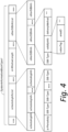
- Fig. 4 shows an example format of SIB Type 1, including schedulingInfoList , si-WindowLength, otherSIBInfoList and possibly other configuration parameters.
- the otherSIBInfoList is a list of otherSIBInfo , which in turn comprises SIB-Type , an identifier of a SIB, validityInfo, validity information of the SIB (a value tag [ valueTag ], validity area identification [ areaID ] and other parameters, such as validity timer, etc.) and deliveryMethod indicating if this SIB is periodically broadcasted or to be transmitted upon request (on-demand).
- the schedulingInfoList comprises a list of scheduling information elements ( schedulingInfo ), each element comprising the periodicity and corresponding SIB types ( si-Periodicity and one or more SIB-Type 's ).
- the actual broadcast opportunity (i.e. timing/resources) of a given SIB may be determined by a pre-determined or a networkconfigured formula as a function of at least the corresponding periodicity.
- the broadcast of the SIB may occur within the duration of the window length ( si-WindowLength ).
- a broadcast opportunity is also referred as a SI window. More than one SIB may be possibly transmitted on a same SI window.
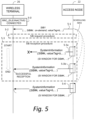
- Fig. 5 is an exemplary message flow diagram of on-demand based SIB acquisition procedure.
- the wireless terminal may decide to obtain the up-to-date version of SIB#k, and may initiate the SIB request procedure represented by act 5-2 and explained herein.
- the wireless terminal may start the SIB reception procedure, shown generally as act 5-3 in Fig. 5 .
- the wireless terminal monitors signals from the access node in the designated Sl windows (shown by dotted rectangles in Fig. 5 ) derived from the scheduling information ( scheduleInfo ) in the SIB1, and thereby attempt to receive the requested SIB#k.
- FIG. 5 shows by act 5-3a a first transmission of the requested SIB# (which is unsuccessful) and by act 5-3b a second transmission of the requested SIB# (which is successful).
- a tail of a vertical down-pointing arrow in the SIB reception procedure depiction of Fig. 5 is associated with start of the SIB reception procedure, while the head of the same vertical down-pointing arrow is associated with end of the SIB reception procedure (at successful reception of the SIB#k.
- Fig. 5 also shows by act 5-4 that other transmissions of the requested system information may also be made even after the wireless terminal has successfully received the sought SIB#k. Accordingly, during the SIB reception procedure, if SIB#k is not successfully received in an SI window, the wireless terminal may repeat reception of SIB#k at the next SI window.
- the wireless terminal may use a counter, which is incremented at every SI window of a particular SIB (e.g. SIB#k).
- the SIB reception procedure may end when the requested SIB(s) are successfully received, or when the counter reaches a maximum counter value.
- the wireless terminal starts a timer at the beginning of the SIB reception procedure.
- the SIB reception procedure may end when the requested SIB(s) are successfully received, or when the timer expires.
- the maximum counter value, or the timer value which may be common for all SIB types or per-SIB type basis, may be pre-configured or configured by network via system information.
- the conditions for the wireless terminal to end the SIB reception process is referred as "termination conditions" herein.
- Fig. 6A , 6B and 6C show three options for the SIB request procedure.
- the request of on-demand delivery for Other SI SIBs may be accomplished by sending a Random Access Preamble, which may comprise a sequence selected from a set of available sequences configured by the access node via Minimum SI. A given sequence is identified by a Preamble Index.
- a Random Access Preamble which may comprise a sequence selected from a set of available sequences configured by the access node via Minimum SI.
- a given sequence is identified by a Preamble Index.
- the access node detects the transmission of a preamble sequence, it may respond to it with Random Access Response, which includes the Preamble Index corresponding to the sequence (see act 6a-2).
- the wireless terminal may validate that the Preamble index in the Random Access Response matches the one associated with the preamble sequence, and then as act 6a-3 send to the access node SystemInformationRequest message that includes the identity of the SIB(s) (e.g. SIB#k) that the wireless terminal desires to receive.
- the access node may send a SystemInformation message acknowledging to the request, indicating that the requested SIB(s) will be broadcasted from the next SI window scheduled for the requested SIB(s).
- the access node may include in Minimum SI a set of Preamble indices, each of which is designated for requesting on-demand delivery of one or more specific Other SI SIBs.
- Fig. 6B illustrates an example SIB request procedure using this configuration, where the wireless terminal in any RRC state may transmit Random Access Preamble sequence given by the Preamble Index associated with the SIB(s) that the wireless terminal has selected (as shown by act 6b-1). When the wireless terminal receives Random Access Response (act 6b-2) including the Preamble Index, it may consider that the request procedure is successful.
- the SIB request procedure in Fig. 6C may be applicable to wireless terminals in RRC_CONNECTED, wherein the SystemInformationRequest message of act 6c-1 is sent without the random access preamble/response.
- the wireless terminal may proceed to the SIB reception procedure if the SIB request procedure is successful. Otherwise, the wireless terminal may think that the serving cell (controlled by the access node) is barred, which will invoke a cell reselection.
- Fig. 7 is a diagrammatic view of an example operation and mode for updating the content of at least one periodically broadcasted SIB.
- Fig. 7 depicts by solid vertical arrows the generation and transmission of system information messages, each solid vertical arrow being a separate system information message containing at least one specific type of SIB.
- the system information messages are shown in Fig. 7 as being generated over a horizontal axis depicting time, and in particular over three "modification periods".
- the modification periods occur between modification period boundaries.
- the modification period boundaries are depicted in Fig. 7 by vertical dashed lines.
- Fig. 7 specifically shows four modification period boundaries: a first or left most modification period boundary which marks or delineates a beginning of a "previous" modification period; a second (from the left of Fig.
- modification period boundary which marks an end of the "previous” modification period and a beginning of a "current” modification period; a third modification period boundary which marks an end of the "current” modification period and beginning of a “next” modification period; and, a fourth modification period boundary which marks an end of the "next” modification period.
- a “modification period” can be any predefined time duration established by any predetermined convention.
- the modification periods may be the same or akin to the concept of modification period as defined for LTE in 3GPP TS 36.304 as well as 36.331. It is anticipated that a similar time delineation may be used in future generations of technology, such as Fifth generation, and accordingly the modification period as used herein encompasses such similar time periods whether explicitly labeled as "modification period" or not.
- the system information messages of Fig. 7 are shown as being periodic, with (for sake of example illustration) six system information messages transmitted between adjacent modification period boundaries.
- the number of system information messages between modification period boundaries is not confined or limited to six, since a greater or lesser number of system information messages may be transmitted.
- Fig. 7 depicts the system information messages of the "previous" modification period and the "current” modification period as "SIB XMT", but the system information messages of the "next" modification period as "SIB' XMT".
- the unprimed reference to the system information messages of the "previous" modification period and the "current” modification period reflects the fact that the contents of the system information blocks of those system information messages do not change during the "previous" modification period and the "current” modification period.
- SIB #2 is the same as the other transmissions of SIB2.
- SIB #3 is the same as the other transmissions of SIB3.
- differently number system information blocks have different contents, but similarly numbered system information blocks have the same content in each of the "previous" modification period and "current” modification period of Fig. 7 .
- Fig. 7 differently depicts the system information messages of the "next" modification period as “SIB' XMT".
- the primed notation "SIB' " indicates that the contents of at least one of the system information blocks carried in at least one of the system information messages has changed since a former modification period, e.g., since the current" modification period in the Fig. 7 scenario.
- the content of the system information block SIB2 may be changed from the content of the similarly numbered system information block SIB2 of the "current” modification period.
- the change of content of any field or information element of the SIB2 results in a "changed" SIB2.
- the wireless terminal may be able to discern or detect that content of a system information block has changed after the content has in fact been changed, e.g., after transmission of a system information message that includes the changed content of a system information block. For example, after the "next" modification period of Fig. 7 has begun, the wireless terminal may be able to determine or detect the changed content of one or more system information blocks. Such retroactive or reactionary detection of changed content of a system information block and switching over to the new system information block content may, however, require additional power consumption on the wireless terminal.
- the access node may broadcast a notification message which is configured to prospectively indicate a change of the content of at least one of the system information blocks.
- the node processor 30 of access node 22 comprises notification message generator 55.
- the notification message generator 55 generates a notification message which is configured to prospectively indicate a change of the content of at least one of the system information blocks.
- the notification message generator 55 generates notification messages NM which serve to alert one or more wireless terminals that the content of one or more system information blocks will change at the next modification period boundary.
- the notification message NM serves to alert one or more wireless terminals that the content of one or more SIBs will change at the next modification period boundary.
- the notification message generator 55 is configured to schedule transmission of plural notification messages. For example, in the context of Fig.
- the access node transmits notification messages NM during the "current" modification period, thereby alerting the one or more wireless terminals that a change of content of one or more system information blocks will occur at the next modification period boundary, e.g., for the "next" modification period.
- the notification messages NM may be generated in advance of a predetermined modification period boundary, in advance of the initial modification period boundary of the "next" modification period. In such case, the predetermined modification period boundary marks a beginning of a period in which the content of the at least one of the system information blocks changes from a previous modification period.
- the notification messages NM are shown by vertically dotted arrow in Fig. 7 . For sake of example Fig. 7 illustrates five such notification messages NM, but a greater or lesser number may be generated.
- the notification messages NM may also be referred to herein as "paging messages", and as such the notification message generator may also be known as paging generator 55.
- the notification messages NM may, in some example embodiments and modes, take the form of conventional paging messages as understood in 3GPP.
- the notification messages NM are not limited to conventional paging messages and need not take the form of any specific type of message.
- the notification messages NMs may be broadcasted messages, not necessarily directed or confined to any particular wireless terminal and not necessarily intended for dissemination to plural wireless terminals served by the access node.
- the radio resources that on which the access node may transmit paging messages may be pre-determined and periodic.
- the access node may send nothing at that particular time.
- the wireless terminal is supposed to monitor at least the agreed resources (paging occasions) to see if there is a paging message addressed to that particular wireless terminal. For example, in the example scenario of Fig. 7 the particular wireless terminal knows, by pre-arranged convention, that the wireless terminal is supposed to monitor the notification messages that are denoted by an asterisk, i.e., notification messages NM*.
- the notification message NM may specifically indicate specifically which SIBs are to be updated.
- the systemInfoModification information element in the Paging message may specifically indicate which SIBs are to be updated.
- Fig. 8A shows an example format of a paging message which comprises a bitmap. Members of the bitmap correspond to respective system information block numbers and indicate by a binary value (e.g., either "1" or "0") whether there will be a content change of the respective system information block at the next modification period boundary.
- the notification message may comprise a field (e.g., systemInfoModification ) which prospectively identifies (e.g., by name or SIB block number or SIB identifier) the particular system information blocks that will have changed content.
- systemInfoModification e.g., by name or SIB block number or SIB identifier
- Fig. 9 is an exemplary message flow for a SIB update notified via Paging message, wherein the SIB#j to be updated is periodically broadcasted.
- the wireless terminal eventually receives the Paging message of act 9-2 that informs the wireless terminal of the upcoming change on SIB#j after the next modification period boundary.
- the wireless terminal may wait for the next modification period boundary, then start the SIB reception process comprising monitoring the SI windows for SIB#j (indicated by scheduleInfo of the Minimum SI) until one of the aforementioned termination conditions.
- the SIB reception process is denoted by the vertical arrow whose tail marks the start of the SBI reception process and whose head marks the end of the SIB reception process, which is at the successful reception of the SystemInformation message 9-3b.
- the procedure of the wireless terminal 26 upon receiving Minimum SI is illustrated in Fig. 10 .
- the wireless terminal 26 in any of the RRC states receives Minimum SI from the currently serving access node via signaling messages, as shown for example by act 10-2. For each SIB type that the wireless terminal needs for desired services, it compares the corresponding value tag in the Minimum SI with the value tag of the stored SIB (if any) (see act 10-3). If the two value tags match, then no action may be taken (go to step 10-10). Otherwise, a check is made at act 10-4 whether the SIB is an on demand SIB. If the SIB is an on demand SIB, as act 10-5 the aforementioned SIB request procedure may be initiated.
- the wireless terminal may proceed to the aforementioned SIB reception procedure.
- the wireless terminal may also being the SIB reception procedure if the check of act 10-4 is negative. If the SIB reception procedure result as checked at act 10-6 is not successful, the wireless terminal may consider the serving cell to be barred, resulting in a cell reselection process (act 10-9).
- the wireless terminal monitors one or more SI windows of the requested SIB(s) (see Fig. 9 ) occurring after the end of the SIB request procedure, until one of the aforementioned termination conditions satisfies (e.g., the SIB reception procedure is deemed successful at act 10-8).
- Fig. 11 illustrates one example operation of the wireless terminal 26 receiving a Paging message (shown as act 11-2).
- act 11-3 the wireless terminal checks if the Paging message indicates an incoming call to this wireless terminal. If so, then the wireless terminal may proceed to RRC connection establishment (act 11-8). Otherwise as act 11-4 the wireless terminal may further check if the message indicates any SIB changes to be scheduled. If it is determined at act 11-4 that at least one SIB type will be changed, as act 11-5 the wireless terminal may wait until the next modification period boundary and then start the SIB reception procedure (as act 11-6) as disclosed earlier.
- This operation of Fig. 11 is aimed for periodically broadcasted SIBs; the operations for on-demand based SIBs are disclosed in following embodiments.
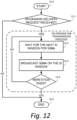
- Fig. 12 is an example operational flow diagram of the access node 22 receiving an on-demand SIB delivery request from a wireless terminal while periodically broadcasting Minimum SI. If as act 12-1 the access node 22 receives the request for SIB#k, the access node 22 may proceed to the on-demand SIB transmission process as shown by act 12-3. As shown by act 12-2, the access node 22 may wait for the next SI window for SIB#k, then (as act 12-3) broadcast the SIB#k on the window. The access node may repeat broadcasting on the following SIB#k SI windows for multiple times until repetition ends (as shown by act 12-4). The number of repetitions may be pre-configured, or equal to the aforementioned maximum counter value configured to wireless terminals via system information.
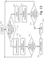
- Fig. 13 is an example operational flow diagram of the access node notifying an upcoming SIB changes to wireless terminals. This operation may start at every modification period boundary. The access node periodically transmits Paging messages at every paging occasion. Act 13-1 of Fig. 13 shows a check to determine if any SIBS are to be updated from the next modification period. When there is no SIB change scheduled, as shown by act 13-2 the systemInfoModification of the message is cleared (no indication of changes). Thereafter a paging message may be transmitted as indicated by act 13-3. When the access node decides to change some of the SIB types, as act 13-5 the information element may be set accordingly to indicate SIB types to be changed, based on the format depicted in Fig. 8A or Fig. 8B .
- the access node may continue sending the Paging message with the information element set (as indicated by act 13-6) until the end of the current modification period (as determined at act 13-7). At the next modification period boundary, where the SIB changes take effective, the access node may update the contents of the SIB(s) as shown by act 13-8.
- Fig. 14 shows an example communications system wherein wireless terminal 26-14 waits for a modification period boundary to initiate an SIB request procedure for an on-demand SIB.
- the terminal processor 40 comprises request generator 72-14 which is configured to initiate the SIB request procedure for an on-demand SIB after waiting for a modification period boundary. That is, the wireless terminal 26-14 initiates a request for the changed SIB after the modification period boundary.
- the SI processor 56 of wireless terminal 26-14 is also configured to receive the requested SIB during the next modification period.
- Other elements and functions of the wireless terminal 26-14 and the access node 22 are similar to and understood from the preceding description of Fig. 2 .
- Fig. 15 shows example, representative acts or steps performed in the communications network of Fig. 14 , e.g., by access node 22 and wireless terminal 26-14, and example messages transmitted therebetween.
- the wireless terminal 26-14 receives a Paging message (corresponding to NM* in Fig. 7 ) which may indicate that SIB#k will be updated from the next modification period.
- the wireless terminal 26-14 may wait for the next modification period boundary, and after the next modification boundary may then initiate the SIB request procedure (represented as act 15-3) to request on-demand delivery of SIB#k.
- the access node may transmit SIB#k in one or more SI windows associated with SIB#k as part of an SIB reception procedure.
- the SIB reception procedure has duration indicated by the vertical arrow of Fig. 15 , wherein the arrow tail indicates start of the SIB reception procedure and the arrow head indicates end of the SIB reception procedure.
- Acts 15-4a and 15-4b comprise acts of the SIB reception procedure which is performed as a result of the SIB request procedure.
- Act 15-4a shows an unsuccessful reception of SIB#k; act 15-4b shows a successful reception of SIB#k.
- Fig. 16 shows example acts or steps performed wireless terminal 26-14 upon receiving the Paging message for the first embodiment.
- Fig. 16 resembles Fig. 11 , but includes additional steps to handle the case where the SIB updates are scheduled on some of the on-demand SIBs.
- Act 16-2 of Fig. 16 shows wireless terminal 26-14 receiving a Paging message.
- act 16-3 the wireless terminal checks if the Paging message indicates an incoming call to this wireless terminal. If so, then the wireless terminal may proceed to RRC connection establishment (act 16-8). Otherwise the wireless terminal may further check if the message indicates any SIB changes to be scheduled.
- act 16-4a the wireless terminal 26-14 may check if the Paging message indicates that the SIB update is for an on-demand SIB; as act 16-4b the wireless terminal 26-14 may check if the Paging message indicates that the SIB update is for a broadcasted SIB. If the Paging message is not for an on-demand SIB, e.g., if the decision of act 16-4a is negative, the check of act 16-4b is performed. Moreover, if the decision of act 16-4b is positive, e.g., if the Paging message is for a broadcasted SIB, as act 16-5a the wireless terminal may wait until the next modification period boundary and then start the SIB reception procedure (as act 16-6) as disclosed earlier.
- the wireless terminal 26-14 waits for the next modification period boundary (act 16-5b). After occurrence of the next modification period boundary, as act 16-11 the wireless terminal 26-14 may begin performance of the SIB request procedure (act 16-11). If the SIB request procedure of act 16-11 is successful, the wireless terminal 26-14 may start the SIB reception procedure (act 16-6) for the on-demand SIB. If the SIB request procedure of act 16-11 is unsuccessful, or if the SIB reception procedure is determined (at act 16-7) to be unsuccessful, cell reselection is performed (act 16-9). If the SIB reception procedure is successful, the procedure of Fig. 16 is terminated (act 16-10).
- the wireless terminal may wait for the next modification period boundary before starting the SIB request procedure, and then initiate the SIB request procedure (act 16-12).
- the SIB request procedure When the SIB request procedure is completed successfully, it may proceed to SIB reception procedure (act 16-7).
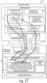
- Fig. 17 shows an example communications system wherein wireless terminal 26-17 initiates the SIB request procedure without waiting for the next modification period boundary, but after the successful completion of the SIB request procedure the wireless terminal 26-17 waits for the next modification period boundary to start the SIB reception procedure.
- the terminal processor 40 comprises request generator 72-17 which is configured to initiate the SIB request procedure for an on-demand SIB without waiting for the next modification period boundary.
- the SI processor 56 of wireless terminal 26-17 may be configured to wait for the next modification period boundary to start the SIB reception procedure.
- the wireless terminal 26-17 and the access node 22 may have an agreement that the SIB reception procedure starts after the modification period boundary when an on-demand SIB is to be updated in the next modification period.
- Such agreement may be pre-configured, or may be configured by the network (e.g., via access node 22) using (for example) system information.
- Other elements and functions of the wireless terminal 26-17 and the access node 22 are similar to and understood from the preceding description of Fig. 2 .
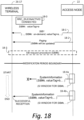
- Fig. 18 shows example, representative acts or steps performed in the communications network of Fig. 14 , e.g., by access node 22 and wireless terminal 26-17, and example messages transmitted therebetween.
- the wireless terminal 26-17 receives a Paging message (corresponding to NM* in Fig. 7 ) which may indicate that SIB#k will be updated from the next modification period.
- the wireless terminal 26-17 does not wait for the next modification period boundary, but before the next modification period boundary begins to initiate the SIB request procedure (represented as act 18-3) to request on-demand delivery of SIB#k.
- the access node may transmit SIB#k in one or more SI windows associated with SIB#k as part of an SIB reception procedure after the next modification period boundary.
- the SIB reception procedure has duration indicated by the vertical arrow of Fig.
- Acts 18-4a and 18-4b comprise acts of the SIB reception procedure which is performed as a result of the SIB request procedure.
- Act 18-4a shows an unsuccessful reception of SIB#k; act 18-4b shows a successful reception of SIB#k.
- Fig. 19 shows example acts or steps performed by the wireless terminal 26-17 of Fig. 17 , and also serves an example operational flow diagram of the wireless terminal for the second embodiment.
- Fig. 19 is similar to Fig. 16 , except that the SIB request procedure is initiated before the next modification period boundary.
- Act 19-2 of Fig. 19 show wireless terminal 26-17 receiving a Paging message.
- act 19-3 the wireless terminal checks if the Paging message indicates an incoming call to this wireless terminal. If so, then the wireless terminal may proceed to RRC connection establishment (act 19-8). Otherwise the wireless terminal may further check if the message indicates any SIB changes to be scheduled.
- act 19-4a the wireless terminal 26-17 may check if the Paging message indicates that the SIB update is for an on-demand SIB; as act 19-4b the wireless terminal 26-17 may check if the Paging message indicates that the SIB update is for a broadcasted SIB. If the Paging message is not for an on-demand SIB, e.g., if the decision of act 19-4a is negative, the check of act 19-4b is performed. Moreover, if the decision of act 19-4b is positive, e.g., if the Paging message is for a broadcasted SIB, as act 11-5a the wireless terminal may wait until the next modification period boundary and then start the SIB reception procedure (as act 11-6) as disclosed earlier.
- the wireless terminal 26-17 does not wait for the next modification period boundary, but instead begins performance of the SIB request procedure (act 19-11). If the SIB request procedure of act 19-11 is successful (act 19-12), the wireless terminal 26-17 waits for the next modification period boundary (act 19-5b). After occurrence of the next modification period boundary, the wireless terminal 26-17 may start the SIB reception procedure (act 19-6) for the on-demand SIB. If the SIB request procedure of act 19-11 is unsuccessful, or if the SIB reception procedure is determined (at act 19-7) to be unsuccessful, cell reselection is performed (act 19-9). If the SIB reception procedure is successful, the procedure of Fig. 19 is terminated (act 19-10).
- the wireless terminal does not wait for the next modification period boundary before starting the SIB request procedure, but initiates the SIB request procedure (act 19-11) before the next modification period boundary.
- the wireless terminal 26-17 may proceed to SIB reception procedure (act 19-7).
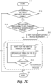
- Fig. 20 shows example, representative acts or steps performed by the access node 22-17 of Fig. 17 .
- the operation for the access node 22-17 of Fig. 17 is similar to the node 22 of Fig. 2 , and the acts thereof resemble those of Fig. 12 but with additional acts as shown in Fig. 20 .
- the access node 22-17 may end the procedure of Fig. 20 (act 20-5).
- the access node 22-17 next determines whether the content of the requested on-demand SIB is to be changed from the next modification period. If the content of the requested on-demand SIB is not to be changed from the next modification period, the access node 22-17 may proceed to the on-demand SIB transmission process as shown by act 20-3. As shown by act 20-2, the access node 22 may wait for the next SI window for SIB#k, then (as act 20-3) broadcast the SIB#k on the window. The access node may repeat broadcasting on the following SIB#k SI windows for multiple times until repetition ends (as shown by act 20-4).
- an on-demand SIB e.g., SIB#k
- the number of repetitions may be pre-configured, or equal to the aforementioned maximum counter value configured to wireless terminals via system information. If, however, the content of the requested on-demand SIB is to be changed from the next modification period, as act 20-6 the access node 22-17 waits for the modification period boundary before performing the on-demand SIB transmission process comprising acts 20-2, 20-3 and 20-4.
- the acts of the access node 22-17 as shown in Fig. 20 are based on Fig. 12 but include, e.g., an act of waiting for the next modification boundary is added in case the requested SIB(s) are to be changed at the next modification period boundary.
- the update of the contents of SIB#k" at the modification period boundary is performed in the act "Update SIB(s)" (act 13-8) in Fig. 13 .
- Fig. 21 shows an example communications system wherein wireless terminal 26-21 and the access node 22-21 have an agreement that whenever an on-demand SIB is updated, the access node 22-21 may notify wireless terminals in the current modification period and automatically transmit the updated SIB at one or more corresponding SI windows from the next modification period, without requiring wireless terminals to send a request.
- the terminal processor 40 comprises SIB processor 56-21 which is configured to automatically receive (without terminal request) an updated on-demand SIB(s) from the next modification period.
- Fig. 21 shows such automatic transmission of the updated SIB as message(s) 2-3-21.
- the access node 22-21 includes functionality 50-21 which, when permitted and/or agreed, automatically transmits on-demand SIBs without requiring terminal request.
- Other elements and functions of the wireless terminal 26-21 and the access node 22-21 are similar to and understood from the preceding descriptions, e.g., the description of Fig. 2 , for example.
- this agreement may be pre-configured in the wireless terminal 26-21 and the access node 22-21.
- an information element indicating whether the automatic transmission of the on-demand SIB may take place from the next modification period is present in a signaling message from the access node 22-21.
- such an information element may be in a Paging message, such as paging message of act 22-2 in Fig. 22 , or may be in Minimum SI (e.g. MIB, SIB1, etc.)
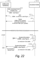
- Fig. 22 shows example, representative acts or steps performed in the communications network of Fig. 21 , e.g., by access node 22-21 and wireless terminal 26-21, and example messages transmitted therebetween.
- the wireless terminal 26-22 receives a Paging message (which may corresponding somewhat to NM* in Fig. 7 ) which may indicate that SIB#k will be updated from the next modification period.
- the paging message of act 22-2 may include an indication (e.g., an information element) that specifies that the on-demand SIBs will be automatically broadcast when updated. Therefore, in view of the fact that SIB#k will be updated from the next modification period and in view of the fact that in the Fig. 22 example embodiment and mode the updated SIB will be automatically provided without requiring request by the wireless terminal 22-21, the wireless terminal 26-21 may, after the next modification period boundary, start the SIB reception procedure without having to make any request for the updates.
- the SIB reception procedure has duration indicated by the vertical arrow of Fig. 22 , wherein the arrow tail indicates start of the SIB reception procedure and the arrow head indicates end of the SIB reception procedure.
- Acts 22-4a and 22-4b comprise acts of the SIB reception procedure which is performed as a result of the SIB request procedure. Act 22-4a shows an unsuccessful reception of SIB#k; act 22-4b shows a successful reception of SIB#k.
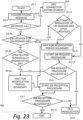
- Fig. 23 shows example acts or steps performed by the wireless terminal 26-21 of Fig. 21 , and also serves an example operational flow diagram of the wireless terminal for the second embodiment.
- Fig. 23 resembles Fig. 19 with additional acts.
- the wireless terminal may simply wait for the boundary and then start the SIB reception process.
- act 23-2 of Fig. 23 show wireless terminal 26-23 receiving a Paging message.
- act 23-3 the wireless terminal checks if the Paging message indicates an incoming call to this wireless terminal. If so, then the wireless terminal may proceed to RRC connection establishment (act 23-8). Otherwise the wireless terminal may further check if the message indicates any SIB changes to be scheduled. Two checks may be performed: as act 23-4a the wireless terminal 26-23 may check if the Paging message indicates that the SIB update is for an on-demand SIB; as act 23-4b the wireless terminal 26-23 may check if the Paging message indicates that the SIB update is for a broadcasted SIB.
- the wireless terminal may wait until the next modification period boundary and then start the SIB reception procedure (as act 23-6) as disclosed earlier.
- act 23-13 the wireless terminal 26-23 checks whether there is agreement or understanding for an automatic broadcast of on-demand SIBs upon updates. If the check of act 23-13 is positive, i.e., if the access node 22-23 can and does supply such automatic broadcast and the wireless terminal 26-23 can accept same, the wireless terminal 26-23 performs act 23-5b to wait for the next modification period boundary and then, after such boundary, starts the SIB reception procedure (act 23-6).
- act 23-11 the wireless terminal 26-23 may begin the SIB request procedure. If it is determined at act 23-12 that the SIB request procedure of act 23-11 is successful, the wireless terminal 26-17 waits for the next modification period boundary (act 23-5a). After occurrence of the next modification period boundary, the wireless terminal 26-17 may start the SIB reception procedure (act 23-6) for the on-demand SIB. If the SIB request procedure of act 23-11 is unsuccessful, or if the SIB reception procedure is determined (at act 23-7) to be unsuccessful, cell reselection is performed (act 23-9). If the SIB reception procedure is successful, the procedure of Fig. 23 is terminated (act 23-10).
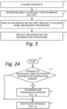
- Fig. 24 is an example operational flow diagram of the access node notifying an upcoming SIB changes to wireless terminals for this embodiment, which is based on Fig. 13 with additional steps.
- the access node 22-21 may check if changes of on-demand SIB(s) have been notified in the previous modification period. If so, as act 24-2 the access node 22-21 may initiate the on-demand SIB transmission process shown in Fig. 12 , and then proceed to the notification operation shown in Fig. 13 as represented by act 24-3 of Fig. 24 , Otherwise, if the determination of act 24-1 is negative, the access node 22-21 may directly proceed to the operation shown in Fig. 13 . It should be understood that the on-demand SIB transmission process and the notification operation may be conducted in parallel.
- Fig. 25 shows an example communications system wherein, when receiving an on-demand SIB request while the requested SIB(s) is to be changed after the next modification period boundary, the access node 22-25 is allowed, if possible (e.g. if there are SI windows scheduled before the boundary), to transmit the requested SIB(s) with updated contents and new value tag(s) before the next modification period boundary.
- the wireless terminal of this embodiment and mode prior to the next modification period boundary, may start the SIB request procedure after receiving the Paging message notifying on-demand SIB changes and may also start the SIB reception procedure following the successful completion of the SIB request procedure.
- Fig. 25 shows the terminal processor 40 comprises request generator 72-25 which is configured, when appropriate, to initiate both the SIB request procedure and the SIB reception procedure for an on-demand SIB without waiting for the next modification period boundary.
- Fig. 25 further shows access node 22-25 as comprising an SIB update advance feature 80.
- the access node 22-25 may transmit the requested SIB(s) with updated contents and new value tag(s) before the next modification period boundary. It should be understood that the updated contents of the SIB(s) will not take effect until the next modification period boundary, and cannot be utilized by the wireless terminal 26-25 until the next modification period boundary.
- the access node 22-25 with its SIB update advance feature 80 may provide the requesting wireless terminal 26-25 with the updated SIB contents in advance of the actual change over which will occur at the modification period boundary. Therefore, "updated” in this context does not necessarily imply that the contents is the currently usable contents, but rather the contents that will be usable at the next modification period boundary.
- Fig. 26 shows example, representative acts or steps performed in the communications network of Fig. 25 , e.g., by access node 22-25 and wireless terminal 26-25, and example messages transmitted therebetween.
- Fig. 26 is an example case where the wireless terminal 26-25 successfully ends the SIB reception process before the next modification period boundary.
- the SIB reception process in some scenarios, may continue beyond the boundary until one of the aforementioned termination conditions.
- the wireless terminal 26-25 receives a Paging message (corresponding to NM* in Fig. 7 ) which may indicate that SIB#k will be updated from the next modification period.
- the wireless terminal 26-25 does not wait for the next modification period boundary, but before the next modification period boundary begins to initiate the SIB request procedure (represented as act 26-3) to request on-demand delivery of SIB#k.
- the access node may transmit SIB#k in one or more SI windows associated with SIB#k as part of an SIB reception procedure.
- the SIB reception procedure has duration indicated by the vertical arrow of Fig.
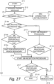
- Fig. 27 shows example acts or steps performed by the wireless terminal 26-25 of Fig. 25 , and also serves an example operational flow diagram of the wireless terminal for the fourth embodiment.
- Fig. 27 is similar to Fig. 19 , except that both the SIB request procedure and the SIB reception procedure may be initiated before the next modification period boundary.
- Act 27-2 of Fig. 19 show wireless terminal 26-25 receiving a Paging message.
- the wireless terminal checks if the Paging message indicates an incoming call to this wireless terminal. If so, then the wireless terminal may proceed to RRC connection establishment (act 27-8). Otherwise the wireless terminal may further check if the message indicates any SIB changes to be scheduled.
- act 27-4a the wireless terminal 26-17 may check if the Paging message indicates that the SIB update is for an on-demand SIB; as act 27-4b the wireless terminal 26-25 may check if the Paging message indicates that the SIB update is for a broadcasted SIB. If the Paging message is not for an on-demand SIB, e.g., if the decision of act 27-4a is negative, the check of act 27-4b is performed. Moreover, if the decision of act 27-4b is positive, e.g., if the Paging message is for a broadcasted SIB, as act 11-5a the wireless terminal may wait until the next modification period boundary and then start the SIB reception procedure (as act 27-6) as disclosed earlier.
- the wireless terminal 26-25 does not wait for the next modification period boundary, but instead begins performance of the SIB request procedure (act 27-11). Thereafter, if the SIB request procedure of act 27-11 was successful, the wireless terminal 26-17 may start the SIB reception procedure (act 27-6) for the on-demand SIB without waiting for the modification period boundary. If the SIB request procedure of act 27-11 is unsuccessful, or if the SIB reception procedure is determined (at act 27-7) to be unsuccessful, cell reselection is performed (act 27). If the SIB reception procedure is successful, the procedure of Fig. 19 is terminated (act 27-10).
- the wireless terminal does not wait for the next modification period boundary before starting the SIB request procedure, and if the SIB request procedure is successful, need not even wait for the modification period boundary for performing the SIB reception procedure.
- Fig. 28 is an example operational flow diagram of the access node 22-25 notifying an upcoming SIB changes to wireless terminals for this embodiment, which is similar to Fig. 13 but with a difference is that the on-demand SIB(s) to be updated is updated without waiting for the end of the current modification boundary. This allows the access node to send, when requested, such on-demand SIB(s) with updated contents even before the next modification boundary.
- Act 28-1 of Fig. 28 shows a check to determine if any SIBS are to be updated after the next modification period. When there is no SIB change scheduled, as shown by act 28-2 the systemInfoModification of the message is cleared (no indication of changes). Thereafter a paging message may be transmitted as indicated by act 28-3.
- the information element may be set accordingly to indicate SIB types to be changed, based on the format depicted in Fig. 8A or Fig. 8B .
- Access node 22-25 may continue sending the Paging message with the information element set (as indicated by act 28-6) until the end of the current modification period (as determined at act 28-8).
- the access node 22-25 may update the on-demand SIBs before the next modification period boundary.
- the access node may update the periodically broadcasted SIBs for the next modification period as shown by act 28-9.
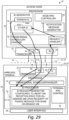
- Fig. 29 shows an example communications system which deals with a situation in which a Paging message notifying changes of on-demand SIB(s) is received after an SIB request procedure requesting the same on-demand SIB(s).
- the terminal processor 40 comprises request generator 72-29 which is configured, when appropriate, to abort the SIB reception procedure for an on-demand SIB if, after commence of the SIB reception procedure and before the next modification period boundary, a paging message is received that indicates that the same on-demand SIB will be (further) updated at the next modification period boundary.
- Fig. 30 shows example, representative acts or steps performed in the communications network of Fig. 29 , e.g., by access node 22-29 and wireless terminal 26-29, and example messages transmitted therebetween.
- the first SIB reception procedure began at a time corresponding to the tail of the top vertical arrow.
- the wireless terminal 26-29 has received the Paging message of act 30-3.
- the paging message of act 30-3 indicating that SIB#k will be updated at the next modification period boundary.
- wireless terminal 26-29 may abort the first SIB reception procedure, at a time approximately shown by the head of the top vertical arrow.
- the wireless terminal 26-29 then waits until the next modification period boundary, and thereafter restart the SIB reception procedure at a time corresponding to the tail of the second vertical arrow of Fig. 30 .
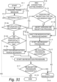
- Fig. 31 shows an example operational flow diagram of the wireless terminal upon receiving the Paging message for this embodiment, where additional acts are added to previous procedures in order to abort an ongoing SIB reception procedure if the Paging message indicates upcoming updates of on-demand SIB(s) which the ongoing SIB reception process is currently trying to acquire.
- act 31-2 of Fig. 23 show wireless terminal 26-29 receiving a Paging message.
- act 31-3 the wireless terminal checks if the Paging message indicates an incoming call to this wireless terminal. If so, then the wireless terminal may proceed to RRC connection establishment (act 31-8). Otherwise the wireless terminal may further check if the message indicates any SIB changes to be scheduled.
- Two checks may be performed: as act 31-4a the wireless terminal 26-31 may check if the Paging message indicates that the SIB update is for an on-demand SIB; as act 31-4b the wireless terminal 26-31 may check if the Paging message indicates that the SIB update is for a broadcasted SIB. If the Paging message is not for an on-demand SIB, e.g., if the decision of act 31-4a is negative, the check of act 31-4b is performed. Moreover, if the decision of act 31-4b is positive, e.g., if the Paging message is for a broadcasted SIB, as act 31-5a the wireless terminal may wait until the next modification period boundary and then start the SIB reception procedure (as act 31-6) as disclosed earlier.
- the wireless terminal 26-31 checks whether there is an on-going SIB reception for the (same) on-demand SIB. If the check of act 31-13 is positive, as act 31-14 the wireless terminal 26-31 aborts the on-going SIB reception for the (same) on-demand SIB. Then, as act 31-5a, the wireless terminal 26-31 waits for the next modification period boundary. After such boundary, the wireless terminal 26-29 performs the SIB reception procedure (act 31-6).
- the wireless terminal 29-31 continues with the wait of act 31-5b, and thereafter starts the SIB request procedure (act 31 -11). If the SIB request procedure of act 31-11 is unsuccessful, or if the SIB reception procedure is determined (at act 31-7) to be unsuccessful, cell reselection is performed (act 31-9). If the SIB reception procedure is successful, the procedure of Fig. 31 is terminated (act 31-10).
- a change of Minimum SI may comprise a change in the types of system information that comprise the first type SIB or the SIB1, e.g., a change of format or content of the first system information block SIB1, such as a change in which parameters are included in SIB1 and/or value of a parameter included in SIB1.
- Such a parameter may be, for an example, an indication of how a particular piece of system information is transmitted (e.g., via periodic broadcast or on-demand).
- Both the sixth and seventh example embodiments and modes deal with situations in which such notification of a change of Minimum SI is received after a wireless terminal has initiated a SIB request procedure to request (what has at least previously been) an on-demand SIB(s).
- the wireless terminal having received the notification that of a change of Minimum SI, is at least alerted to the possibility that the change of Minimum SI may affect the on-demand SIB that has been requested.
- the wireless terminal is at least alerted to the possibility that the sought on-demand SIB may (as a result of the change of Minimum SI) transition from an on-demand SIB to a periodically broadcast SIB. If the sought formerly on-demand SIB is indeed changed to periodically broadcast SIB, then the wireless terminal knows that the sought SIB will henceforth be broadcasted so that no special request need be made for the sought SIB. Likewise, the change of the Minimum SI may affect the transmission timing of the requested on-demand SIB. In this case, the wireless terminal may need to change its reception schedule accordingly.
- Fig. 32 shows an example communications system of the sixth example embodiment and mode which deals with a case wherein a Paging message notifying changes of Minimum SI (e.g. SIB1) is received after the SIB request procedure requesting on-demand SIB(s), and in which the wireless terminal 26-32 may abort the ongoing SIB reception procedure upon receipt of the Paging message.
- the access node 22-32 comprises a paging message generator 82 which generates a paging message, as well as a change of Minimum SI functionality 84.
- the Minimum SI functionality 84 causes the paging message generator 82 to include notification of change of Minimum SI in the paging message.
- An example paging message is shown as message 2-4 in Fig.
- Fig. 32 further shows the terminal processor 40 comprises request generator 72-32 which is configured, when appropriate, to abort the SIB reception procedure for an on-demand SIB upon reception of a paging message if, after commence of the SIB reception procedure, the paging message indicates a change in Minimum SI.
- request generator 72-32 which is configured, when appropriate, to abort the SIB reception procedure for an on-demand SIB upon reception of a paging message if, after commence of the SIB reception procedure, the paging message indicates a change in Minimum SI.
- Other elements and functions of the wireless terminal 26-32 and the access node 22-32 are similar to and understood from the preceding descriptions, e.g., including but not limited to the descriptions of Fig. 2 , Fig. 14 , Fig. 17 , Fig. 21 , Fig. 25 , and Fig. 29 .
- Both Fig. 33A and Fig. 33B deal with the case where the Paging message notifying changes of Minimum SI (e.g. SIB1) is received after the SIB request procedure requesting on-demand SIB(s).
- the wireless terminal 26-32 may abort the ongoing SIB reception procedure upon receipt of the Paging message, wait for the next modification boundary then reacquire the updated Minimum SI, which may comprise delivery and scheduling information of the SIB(s) that the wireless terminal has requested in the earlier SIB request procedure. Such information may or may not be the same as the one contained in the previously received Minimum SI. Therefore, the wireless terminal 26-32 may use the information included in this updated Minimum SI regardless. For example, as shown in Fig.
- the wireless terminal 26-32 may re-initiate the SIB requesting procedure, followed by the SIB reception procedure with the scheduling information of the SI windows included in the updated Minimum SI.
- the wireless terminal 26-32 may directly proceed to initiating the SIB reception procedure.
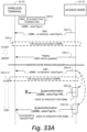
- Fig. 33A shows example, representative acts or steps performed in the communications network of Fig. 32 , e.g., by access node 22-32 and wireless terminal 26-32, and example messages transmitted therebetween.
- the wireless terminal 26-32 receives paging message 33A-3 which indicates a change in Minimum SI, i.e., that the SIB1 will be updated.
- the wireless terminal 26-32 aborts the SIB reception procedure (at a time approximately shown by the head of the top vertical arrow of Fig. 33A ).
- the wireless terminal 26-32 realizes there is a possibility that the sought SIB#k, having been an on-demand SIB, may hereafter be transitioned to SIB1, e.g., may hereafter be a periodically broadcast SIB.
- the wireless terminal 26-32 begins a second SIB request procedure to request the SIB#k. If the second SIB request procedure of act 33A-2-2 is successful, a second SIB reception procedure is begun.
- the second SIB reception procedure has duration indicated by the lower vertical arrow of Fig. 33A , wherein the arrow tail indicates start of the second SIB reception procedure and the arrow head indicates end of the second SIB reception procedure.
- Acts 33A-5a and 33A-5b comprise acts of the SIB reception procedure which is performed as a result of the SIB request procedure.
- Act 33A-5a shows an unsuccessful reception of SIB#k; act 33A-5b shows a successful reception of SIB#k.
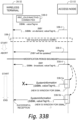
- the sought SIB#k is changed to a periodically broadcast SIB, as is shown by the SIB1 message 33B-4 which is broadcast after the next modification period boundary. Knowing then that the sought SIB#k is now a periodically broadcast SIB, the wireless terminal 26-32 need not begin a second SIB request procedure to request the SIB#k, but can instead immediately enter a second SIB reception procedure wherein the sought SIB#k will be broadcast.
- the second SIB reception procedure has duration indicated by the lower vertical arrow of Fig. 33B , wherein the arrow tail indicates start of the second SIB reception procedure and the arrow head indicates end of the second SIB reception procedure. Similar to Fig.
- Acts 33B-5a and 33B-5b comprise acts of the second SIB reception procedure, with act 33B-5a showing an unsuccessful reception of SIB#k and act 33B-5b showing a successful reception of SIB#k.
- the scenario of Fig. 33B thus does not require a second SIB request procedure, in view of anticipated broadcast of the now SIB1-included SIB#k. Acts of Fig. 33B occurring before the modification period boundary are similar to those of Fig. 33A .
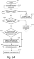
- Fig. 34 shows an example operational flow diagram of the wireless terminal upon receiving the Paging message for this embodiment, where additional acts are added to previous procedures in order to abort an ongoing SIB reception procedure if the Paging message indicates a change in Minimum SI.
- act 34-2 of Fig. 34 show wireless terminal 26-32 receiving a Paging message.
- act 34-3 the wireless terminal checks if the Paging message indicates an incoming call to this wireless terminal. If so, then the wireless terminal 26-32 may proceed to RRC connection establishment (act 34-4). Otherwise the wireless terminal 26-32 checks as act 34-5 if there has been a change in Minimum SI, i.e., if there are any SIB updates for Minimum SI.
- the wireless terminal 26-32 proceeds to perform logic associated with and following acts described as "SIB updates for on-demand SIB?" in any appropriate one of Fig. 16 , Fig. 19 , Fig. 23 , Fig. 27 , or Fig. 31 described herein. If there has been a change in Minimum SI, as act 34-7 the wireless terminal 26-32 checks there is an on-gong SIB receipt for an on-demand SIB. In other words, the wireless terminal 26-32 determines if it is in the middle of a process of attempting to receive the on-demand SIB which the wireless terminal 26-32 has already requested. If there is an on-going SIB reception procedure, the on-going SIB reception procedure is aborted as act 34-8.
- act 34-9 comprises the wireless terminal 26-32 waiting for the next modification period boundary. Thereafter, as act 34-10, the wireless terminal 26-32 acquires the Minimum SI as understood with reference to Fig. 10 .
- Fig. 34 thus shows that, upon acquiring the Paging message (such as paging message 33B-3 of Fig. 33 , an extra condition checking of act 34-5 is added to see if changes on the Minimum SI will be taking place at the next modification period boundary. If not, the wireless terminal 26-34 may fall back to one of the previous embodiments, specifically proceeding to the step "SIB updates for on-demand SIB?" as shown in an appropriate one of Fig. 16 , 19 , 23 , 27 , or 31 . Otherwise, the wireless terminal 26-32 may abort the ongoing SIB reception process (if any), wait for the next modification period boundary, then attempt to acquire the updated Minimum SI as shown in Fig. 10 .
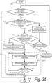
- Fig. 35 is an example operational flow diagram of the access node 22-32 receiving an on-demand SIB delivery request from a wireless terminal and includes a step (act 35-2) to check if changes on the Minimum SI are scheduled from the next modification period. If that is the case, the access node 22-32 may postpone transmissions of the requested SIB(s) even if there are SI windows for the SIB(s) before the next modification boundary. After the next modification boundary, the access node re-evaluate the delivery method of the requested SIB(s); if it remains on-demand, then it may wait for a new request from wireless terminals, otherwise it may initiate periodic broadcast of the SIB(s), comprising repeating transmission of the SIB(s) in every designated SI window.
- the access node 22-32 may end the procedure of Fig. 35 (act 35-8).
- the access node 22-32 determines there is to be a change of Minimum SI (i.e., that the Minimum SI is to be changed from the next modification period boundary).
- the network e.g. the access node 22-32, may make a decision when and how to change the configuration parameters in Minimum SI (SIB1), based on such factors (for example) as operation environmental changes, network configuration changes, network traffic changes, network congestion, and the like.
- the access node 22-32 next determines whether the content of the requested on-demand SIB is to be changed from the next modification period. If the content of the requested on-demand SIB is not to be changed from the next modification period, the access node 22-32 may proceed to the on-demand SIB transmission process, where the access node 22-32 may (as act 35-5) wait for the next SI window for SIB#k, then (as act 35-6) transmit the SIB#k on the window. The access node 22-32 may repeat transmitting on the following SIB#k SI windows for multiple times until repetition ends (as shown by act 35-7).
- the number of repetitions may be pre-configured, or equal to the aforementioned maximum counter value configured to wireless terminals via system information. If, however, the content of the requested on-demand SIB is to be changed from the next modification period, as act 35-4 the access node 22-32 waits for the modification period boundary before performing the on-demand SIB transmission process comprising acts 35-5, 35-6 and 35-7. But if it were determined at act 35-2 that there is to be a change of Minimum SI, the access node 22-32 performs acts 35-9 and 35-10. Act 35-9 comprises the access node 22-32 waiting for the next modification period boundary. Act 35-10 comprises the access node 22-32 making a determination if the requested SIB(s) are on-demand. If the requested SIB(s) are not on-demand, the requested SIBs are periodically broadcast as generally indicated by act 35-11. If the requested SIB(s) are on-demand, execution loops back to act 35-1.
- Fig. 36 shows an example communications system of the seventh example embodiment and mode which deals with a case wherein a Paging message notifying changes of Minimum SI (e.g. SIB1) is received after the SIB request procedure requesting on-demand SIB(s), and in which the wireless terminal 26-36 may abort the ongoing SIB reception procedure at a modification period boundary.
- the access node 22-36 comprises a paging message generator 82 which generates a paging message, as well as a change of Minimum SI functionality 84.
- the Minimum SI functionality 84 causes the paging message generator 82 to include notification of change of Minimum SI in the paging message.
- An example paging message is shown as message 2-4 in Fig.
- Fig. 36 further shows the terminal processor 40 comprises request generator 72-36 which is configured, when appropriate, to abort the SIB reception procedure for an on-demand SIB at a next modification period boundary if, after commencing of the SIB reception procedure, the paging message indicates a change in Minimum SI.
- request generator 72-36 which is configured, when appropriate, to abort the SIB reception procedure for an on-demand SIB at a next modification period boundary if, after commencing of the SIB reception procedure, the paging message indicates a change in Minimum SI.
- Other elements and functions of the wireless terminal 26-36 and the access node 22-36 are similar to and understood from the preceding descriptions, e.g., including but not limited to the descriptions of Fig. 2 , Fig. 14 , Fig. 17 , Fig. 21 , Fig. 25 , Fig. 29 , and Fig. 32 .
- the seventh embodiment is thus a variation of the sixth embodiment and mode, wherein the wireless terminal 26-36 continues the SIB reception procedure even when receiving the Paging message indicating changes of Minimum SI from the next modification period.
- the wireless terminal 26-36 of the Fig. 36 embodiment and mode may abort the SIB reception process at the next modification period boundary if it has not successfully received the requested SIB(s) during the current modification period, e.g., the modification period occurring before the modification boundary depicted in Fig. 37A .
- the wireless terminal 26-36 of Fig. 36 may then attempt to acquire the updated Minimum SI, which may comprise delivery and scheduling information of the SIB(s) that the wireless terminal has requested in the earlier SIB request procedure.
- the wireless terminal 26-36 may use the information included in this updated Minimum SI regardless.
- Fig. 37A illustrates a case where the updated Minimum SI indicates the previously requested SIB(s) (e.g. SIB#k) is on-demand basis, which may have the wireless terminal restart the SIB request procedure, followed by the SIB reception procedure.
- Fig. 37A shows example, representative acts or steps performed in the communications network of Fig. 36 , e.g., by access node 22-36 and wireless terminal 26-36, and example messages transmitted therebetween. In the example message flow shown in Fig.
- the wireless terminal 26-36 receives paging message 37A-3 which indicates a change in Minimum SI, i.e., that the SIB1 will be updated. But unlike in the sixth example embodiment and mode, the wireless terminal 26-36 does not immediately abort the SIB reception procedure upon reception of the paging message 37A-3. Rather, as shown by other acts before occurrence of the modification period boundary in Fig. 37A , e.g., during the current modification period, the wireless terminal 26-36 continues to attempts to acquire the sought SIB#k in a SIB reception procedure indicated by the top vertical arrow of Fig. 37A until the next modification period.
- the wireless terminal 26-36 is not successful in receiving the sought SIB#k, as indicated by failed SystemInformation message 37A-4.
- the SIB reception procedure is only then aborted at the next modification period boundary, as it was mentioned above that wireless terminal 26-36 of the Fig. 36 embodiment and mode may abort the SIB reception process at the next modification period boundary if it has not successfully received the requested SIB(s).
- the wireless terminal 26-36 receives the SIB I message 37A-5 which is broadcast after the next modification period boundary.
- the SIB1 message 37A-5 in the case of Fig.
- the wireless terminal 26-36 begins a second SIB request procedure to request the SIB#k. If the second SIB request procedure of act 37A-6 is successful, a second SIB reception procedure is begun.
- the second SIB reception procedure has duration indicated by the lower vertical arrow of Fig. 37A , wherein the arrow tail indicates start of the second SIB reception procedure and the arrow head indicates end of the second SIB reception procedure.
- Acts 37A-7a and 37A-7b comprise acts of the SIB reception procedure which is performed as a result of the SIB request procedure.
- Act 37A-7a shows an unsuccessful reception of SIB#k; act 37A-7b shows a successful reception of SIB#k.
- the sought SIB#k is changed to Minimum SI, as is shown by the SIB1 message 37B-5 which is broadcast after the next modification period boundary. Knowing then that the sought SIB#k is now a periodically broadcasted SIB, the wireless terminal 26-36 need not begin a second SIB request procedure to request the SIB#k, but can instead immediately enter a second SIB reception procedure wherein the sought SIB#k will be broadcast.
- the second SIB reception procedure has duration indicated by the lower vertical arrow of Fig. 37B , wherein the arrow tail indicates start of the second SIB reception procedure and the arrow head indicates end of the second SIB reception procedure. Similar to Fig.
- Acts 37B-7a and 37B-7b comprise acts of the second SIB reception procedure, with act 37B-7a showing an unsuccessful reception of SIB#k and act 37B-7b showing a successful reception of SIB#k.
- the scenario of Fig. 37B thus does not require a second SIB request procedure, in view of anticipated broadcast of the now SIB1-included SIB#k. Acts of Fig. 37B occurring before the modification period boundary are similar to those of Fig. 37B .
- Fig. 37B is a case where at the modification period boundary the delivery method of the requested SIB(s) changes from on-demand to periodic broadcast.
- the wireless terminal 26-36 may directly proceed to the SIB reception procedure.
- wireless terminal 26-36 may end the SIB reception procedure, as shown in Fig. 37C .
- the wireless terminal 26-36 after performance of the SIB request procedure of act 37C-2, the wireless terminal 26-36 performs a SIB reception procedure as indicated by the top arrow of Fig. 37C .
- the wireless terminal 26-36 receives the paging message of act 37C-3 which indicates that the SIB1 will be updated.
- the wireless terminal 26-36 does not abort the SIB reception procedure, but rather continues the SIB reception procedure in an attempt to receive the sought SIB#k in the current modification period.
- the scenario of Fig. 37C differs from the scenarios of Fig. 37A and Fig. 37C in that in the SIB reception procedure of Fig. 37C the wireless terminal 26-36 is successful in receiving the sought SIB#k in the current modification period, e.g., before the modification period boundary, as indicated by act 37C-4. After the modification period boundary the wireless terminal 26-36 may continue to receive other SIB1 messages, as indicated by message 37C-5.
- the wireless terminal 26-36 may eventually acquire the updated Minimum SI, and make a decision of further actions (if any) based on the contents of the updated Minimum SI.
- Fig. 38 shows an example operational flow diagram of the wireless terminal upon receiving the Paging message for this embodiment, where additional acts are added to previous procedures in order to abort an ongoing SIB reception procedure if the Paging message indicates a change in Minimum SI.
- act 38-2 of Fig. 38 show wireless terminal 26-36 receiving a Paging message.
- act 38-3 the wireless terminal checks if the Paging message indicates an incoming call to this wireless terminal. If so, then the wireless terminal 26-36 may proceed to RRC connection establishment (act 38-4). Otherwise the wireless terminal 26-36 checks as act 38-5 if there has been a change in Minimum SI, i.e., if there are any SIB updates for Minimum SI.
- the wireless terminal 26-36 proceeds to perform logic associated with and following acts described as "SIB updates for on-demand SIB?" in any appropriate one of Fig. 16 , Fig. 19 , Fig. 23 , Fig. 27 , or Fig. 31 described herein. If there has been a change in Minimum SI, as act 38-7 the wireless terminal 26-36 checks there is an on-gong SIB receipt for an on-demand SIB. In other words, the wireless terminal 26-36 determines if it is in the middle of a process of attempting to receive the on-demand SIB which the wireless terminal 26-36 has already requested.
- the wireless terminal 26-36 does not immediately abort the on-going SIB reception procedure. Rather, as act 38-8A the wireless terminal 26-36 adds a termination condition: that the SIB reception procedure is to end at the next modification period boundary. As act 38-8B, a check is then made whether the sought SIB#k has been acquired before the next modification period boundary. If the sought SIB#k has been acquired before the next modification period boundary, the wireless terminal 26-36 waits for the next modification period boundary (act 38-9) and thereafter performs Minimum SI acquisition (act 38-10). If the sought SIB#k has not been acquired before the next modification period boundary, the wireless terminal 26-36 performs Minimum SI acquisition (act 38-10). If there is no on-going SIB reception procedure, as act 38-9 the wireless terminal 26-36 (act 38-9) and thereafter performs Minimum SI acquisition (act 38-10).
- Fig. 38 thus shows that, upon acquiring the Paging message, wherein after checking an incoming call for this wireless terminal, an extra step (act 38-5) is added to check if the Paging message indicates upcoming changes on the Minimum SI from the next modification period. If not, then similar to the sixth embodiment, the flow may proceed to the step "SIB updates for on-demand SIB?" as shown in an appropriate one of Fig. 16 , 19 , 23 , 27 , or 31 . Otherwise, the wireless terminal 26-36 further check if there is any SIB reception process currently ongoing for on-demand SIB(s) (act 38-7). If not, the wireless terminal may simply wait for the next modification period (act 38-9) and then start to acquire the Minimum SI (act 38-10) as shown in Fig. 10 .
- the wireless terminal 26-36 may continue the ongoing SIB reception procedure, in which, one new termination condition (act 38-8A) is now added to the aforementioned termination conditions; the SIB reception procedure ends at the next modification period boundary.
- one new termination condition (act 38-8A) is now added to the aforementioned termination conditions; the SIB reception procedure ends at the next modification period boundary.
- the wireless terminal 26-36 fails to receive the requested SIB(s) before the modification period boundary, it may terminate the ongoing SIB reception procedure unsuccessfully.
- the wireless terminal may wait for the next modification period boundary (act 38-9) if it is before the boundary and proceed to the Minimum SI acquisition shown in Fig. 9 , or directly proceed to the Minimum SI acquisition if already after the boundary (act 38-10).
- Fig. 39 is an example operational flow diagram of the access node 22-36 receiving an on-demand SIB delivery request from a wireless terminal, which is based on Fig. 12 with an extra act after waiting for the next SI window for the requested SIB(s) (e.g. SIB#k) to check (act 39-3) to see if now it is in a new modification period. If so, access node 22-36 may further check if the Minimum SI has changed in this modification period (act 39-7). If not, the flow may resume the ongoing (repetitive) transmission cycle of the requested SIB(s). Otherwise the transmission cycle is terminated, and the access node may further checks if the requested SIB(s) remain on-demand after the Minimum SI change (act 39-8).
- the access node may wait for a next request (act 39-1).
- the access node may initiate the periodic broadcast procedure as understood with respect to Fig. 35 , for example.
- the access node 22-36 may end the procedure of Fig. 39 (act 39-8). If a request for an on-demand SIB has been received, as act 39-2 the wireless terminal 26-36 waits for the next SI window for the requested SIB(s) (e.g. SIB#k), and then as act 39-3 checks to see if now it is in a new modification period. If it is not a new modification period, as act 39-7 the access node 22-36 may proceed to the on-demand SIB transmission process, where the access node 22-36 may (as act 39-4) transmit the SIB#k on the window.
- the wireless terminal 26-36 waits for the next SI window for the requested SIB(s) (e.g. SIB#k)
- act 39-3 checks to see if now it is in a new modification period. If it is not a new modification period, as act 39-7 the access node 22-36 may proceed to the on-demand SIB transmission process, where the access node 22-36 may (as act 39-4) transmit
- the access node 22-36 may repeat transmitting on the following SIB#k SI windows for multiple times until repetition ends (as shown by act 39-5). The number of repetitions may be pre-configured, or equal to the aforementioned maximum counter value configured to wireless terminals via system information. If it is a new modification period, as act 39-7 the access node 22-36 determines if there is to be a change of Minimum SI (i.e., that the Minimum SI is to be changed from the next modification period boundary). As mentioned above, the network, e.g. the access node 22-32, may make a decision when and how to change the configuration parameters in Minimum SI (SIB1), based on such factors (for example) as operation environmental changes, network configuration changes, network traffic changes, network congestion, and the like.
- SIB1 Minimum SI
- the access node 22-36 may proceed to the on-demand SIB transmission process, where the access node 22-36 may (as act 39-4) transmit the SIB#k on the window, as described above. If there is a change of Minimum SI, as act 39-8 the access node 22-36 makes a determination if the requested SIB(s) are on-demand. If the requested SIB(s) are not on-demand, the requested SIBs are periodically broadcast as generally indicated by act 39-9. If the requested SIB(s) are on-demand, execution loops back to act 39-1.
- node 22 and wireless terminal 26 are, in example embodiments, implemented by electronic machinery, computer, and/or circuitry.
- the node processors 30 and terminal processors 40 of the example embodiments herein described and/or encompassed may be comprised by the computer circuitry of Fig. 32.
- Fig. 32 shows an example of such electronic machinery or circuitry, whether node or terminal, as comprising one or more processor(s) circuits 190, program instruction memory 192; other memory 194 (e.g., RAM, cache, etc.); input/output interfaces 196; peripheral interfaces 198; support circuits 199; and busses 200 for communication between the aforementioned units.
- the program instruction memory 192 may comprise coded instructions which, when executed by the processor(s), perform acts including but not limited to those described herein.
- each of node processor 30 and terminal processor 40 for example, comprise memory in which non-transient instructions are stored for execution.
- the memory 194, or computer-readable medium may be one or more of readily available memory such as random access memory (RAM), read only memory (ROM), floppy disk, hard disk, flash memory or any other form of digital storage, local or remote, and is preferably of non-volatile nature.
- RAM random access memory
- ROM read only memory
- floppy disk hard disk
- flash memory any other form of digital storage, local or remote, and is preferably of non-volatile nature.
- the support circuits 199 are coupled to the processors 190 for supporting the processor in a conventional manner. These circuits include cache, power supplies, clock circuits, input/output circuitry and subsystems, and the like.
- the device hosting the processor may comprise at least one processor and at least one memory including computer program code, the memory and the computer program code being configured to, working with the at least one processor, to cause the host device to perform the functions afore-described.
- the first example embodiment and mode of wireless terminal 26-14 comprises at least one processor and at least one memory including computer program code, the memory and the computer program code being configured to, working with the at least one processor, to cause the wireless terminal to wait for a modification period boundary to initiate an SIB request procedure for an on-demand SIB.
- the second example embodiment and mode of wireless terminal 26-17 comprises at least one processor and at least one memory including computer program code, the memory and the computer program code being configured to, working with the at least one processor, to cause the wireless terminal to initiate the SIB request procedure without waiting for the next modification period boundary, but after the successful completion of the SIB request procedure to wait for the next modification period boundary to start the SIB reception procedure.
- the third example embodiment and mode of wireless terminal 26-21 comprises at least one processor and at least one memory including computer program code, the memory and the computer program code being configured to, working with the at least one processor, to cause the wireless terminal to whenever an on-demand SIB is updated, receive from the access node an automatic transmission of the updated SIB at one or more corresponding SI windows from the next modification period, without the wireless terminal being required to send a request.
- the fourth example embodiment and mode of wireless terminal 26-25 comprises at least one processor and at least one memory including computer program code, the memory and the computer program code being configured to, working with the at least one processor, to cause the wireless terminal, when appropriate, to initiate both the SIB request procedure and the SIB reception procedure for an on-demand SIB without waiting for the next modification period boundary.
- the fifth example embodiment and mode of wireless terminal 26-29 comprises at least one processor and at least one memory including computer program code, the memory and the computer program code being configured to, working with the at least one processor, to cause the wireless terminal, when a Paging message notifying changes of on-demand SIB(s) is received after initiating an on-going SIB request procedure requesting the same on-demand SIB(s), to abort the on-going SIB request procedure.
- the sixth example embodiment and mode of wireless terminal comprises at least one processor and at least one memory including computer program code, the memory and the computer program code being configured to, working with the at least one processor, to cause the wireless terminal to abort an ongoing SIB reception procedure upon receipt of the Paging message that indicates a change in Minimum SI.
- the seventh example embodiment and mode of wireless terminal comprises at least one processor and at least one memory including computer program code, the memory and the computer program code being configured to, working with the at least one processor, to cause the wireless terminal continue, at least to a next modification period boundary, an ongoing SIB reception procedure upon receipt of the Paging message that indicates a change in Minimum SI.
- the technology disclosed herein solves problems in the field of telecommunications, including problems in telecommunications nodes such wireless terminals and access nodes, as well as computers/processors and hardware comprising such nodes.
- System information is of utmost importance to the operation of telecommunication nodes, so that each node can obtain the necessary network information to coordinate and communicate with other nodes and to perform its desired functions.
- the system information is quite extensive and complex, and may be changeable/updateable due to network and operating conditions, for example. Efficiently obtaining and using the system information is challenging, particularly in view of numerous other telecommunications functions that may be simultaneously on-going based on the system information.
- the technology disclosed herein affords the communications nodes the computerized and other configuration in order to obtain the system information earlier and more efficiently, thereby avoiding waste of time and processing resources.
- the processes and methods of the disclosed embodiments may be discussed as being implemented as a software routine, some of the method steps that are disclosed therein may be performed in hardware as well as by a processor running software. As such, the embodiments may be implemented in software as executed upon a computer system, in hardware as an application specific integrated circuit or other type of hardware implementation, or a combination of software and hardware.
- the software routines of the disclosed embodiments are capable of being executed on any computer operating system, and is capable of being performed using any CPU architecture.
- the instructions of such software are stored on non-transient computer readable media.
- the functional blocks may include or encompass, without limitation, digital signal processor (DSP) hardware, reduced instruction set processor, hardware (e.g., digital or analog) circuitry including but not limited to application specific integrated circuit(s) [ASIC], and/or field programmable gate array(s) (FPGA(s)), and (where appropriate) state machines capable of performing such functions.
- DSP digital signal processor
- ASIC application specific integrated circuit
- FPGA field programmable gate array
- a computer is generally understood to comprise one or more processors or one or more controllers, and the terms computer and processor and controller may be employed interchangeably herein.
- the functions may be provided by a single dedicated computer or processor or controller, by a single shared computer or processor or controller, or by a plurality of individual computers or processors or controllers, some of which may be shared or distributed.
- processor or “controller” shall also be construed to refer to other hardware capable of performing such functions and/or executing software, such as the example hardware recited above.
- Nodes that communicate using the air interface also have suitable radio communications circuitry.
- the technology can additionally be considered to be embodied entirely within any form of computer-readable memory, such as solid-state memory, magnetic disk, or optical disk containing an appropriate set of computer instructions that would cause a processor to carry out the techniques described herein.
- the technology disclosed herein is directed to solving radio communications-centric issues and is necessarily rooted in computer technology and overcomes problems specifically arising in radio communications. Moreover, in at least one of its aspects the technology disclosed herein improves the functioning of the basic function of a wireless terminal and/or node itself so that, for example, the wireless terminal and/or node can operate more effectively by prudent use of radio resources.
Landscapes
- Engineering & Computer Science (AREA)
- Computer Networks & Wireless Communication (AREA)
- Signal Processing (AREA)
- Computer Security & Cryptography (AREA)
- Databases & Information Systems (AREA)
- Mobile Radio Communication Systems (AREA)
- Circuits Of Receivers In General (AREA)
Claims (8)
- Drahtlos-Endgerät (26, 26-14, 26-17, 26-21, 26-25, 26-29, 26-32, 26-36), aufweisend:eine Empfängereinheit (46), die derart konfiguriert ist, dass sie von einer Basisstationsvorrichtung (22, 22-17, 22-21, 22-25, 22-29, 22-32, 22-36) einen minimalen Systeminformations-, SI-, Block empfängt, der Planungsinformationen beinhaltet, die zum Konfigurieren eines oder mehrerer SI-Fenster verwendet werden, wobei das eine oder die mehreren SI-Fenster eine periodische Sendegelegenheit(en) für einen oder mehrere entsprechende andere Systeminformationsblöcke, SIB, sind;eine Prozessoreinheit (40), die derart konfiguriert ist, dass sie das eine oder mehrere SI-Fenster anhand der Planungsinformationen bestimmt;wobei die Empfängereinheit (46) ferner derart konfiguriert ist, dass sie einen Empfangsvorgang durchführt, um zumindest einen der anderen SIBs innerhalb des einen oder mehrerer SI-Fenster eines aktuellen Änderungszeitraums zu empfangen;wobei der Empfangsvorgang:in dem Fall endet, dass zumindest einer der anderen SIBs erfolgreich empfangen wurde, undbis zum Ende des aktuellen Änderungszeitraums fortgesetzt wird, wenn der zumindest eine der anderen SIBs nicht innerhalb eines oder mehrerer SI-Fenster des aktuellen Änderungszeitraums empfangen wird.
- Drahtlos-Endgerät (26, 26-14, 26-17, 26-21, 26-25, 26-29, 26-32, 26-36) nach Anspruch 1, wobei der aktuelle Änderungszeitraum einer von mehreren Änderungszeiträumen ist, die von der Basisstationsvorrichtung (22, 22-17, 22-21, 22-25, 22-29, 22-32, 22-36) konfiguriert werden, wobei die mehreren Änderungszeiträume sich wiederholende Zeitspannen sind.
- Drahtlos-Endgerät (26, 26-14, 26-17, 26-21, 26-25, 26-29, 26-32, 26-36) nach Anspruch 1, wobei die Empfängereinheit (46) ferner derart konfiguriert ist, dass sie den Empfangsvorgang bei einem nächsten Änderungszeitraum abbricht.
- Drahtlos-Endgerät (26, 26-14, 26-17, 26-21, 26-25, 26-29, 26-32, 26-36) nach Anspruch 1, wobei die Empfängereinheit (46) derart konfiguriert ist, dass sie den Empfangsvorgang in dem aktuellen Änderungszeitraum fortsetzt, selbst wenn die Empfängereinheit (46) eine Benachrichtigungsnachricht empfängt, die eine Änderung des Inhalts des minimalen Systeminformations-, SI-, Blocks oder eines oder mehrerer der anderen Systeminformationsblöcke (SIB) mitteilt.
- Verfahren in einem Drahtlos-Endgerät (26, 26-14, 26-17, 26-21, 26-25, 26-29, 26-32, 26-36), umfassend:Empfangen, von einer Basisstationsvorrichtung (26, 26-14, 26-17, 26-21, 26-25, 26-29, 26-32, 26-36), eines minimalen Systeminformations-, SI-, Blocks, der Planungsinformationen beinhaltet, die zum Konfigurieren eines oder mehrerer SI-Fenster verwendet werden, wobei das eine oder die mehreren SI-Fenster eine periodische Sendegelegenheit(en) für einen oder mehrere entsprechende andere Systeminformationsblöcke, SIB, sind;Bestimmen des/der einen oder mehreren SI-Fenster anhand der Planungsinformationen;Durchführen eines Empfangsvorgangs, um zu versuchen, zumindest einen der anderen SIBs innerhalb des einen oder mehrerer SI-Fenster eines aktuellen Änderungszeitraums zu empfangen; und wobei der Empfangsvorgang:in dem Fall endet, dass zumindest einer der anderen SIBs erfolgreich empfangen wurde, undbis zum Ende des aktuellen Änderungszeitraums fortgesetzt wird, wenn der zumindest eine der anderen SIBs nicht innerhalb eines oder mehrerer SI-Fenster des aktuellen Änderungszeitraums empfangen wird.
- Verfahren nach Anspruch 5, wobei der aktuelle Änderungszeitraum einer von mehreren Änderungszeiträumen ist, die von der Basisstationsvorrichtung (26, 26-14, 26-17, 26-21, 26-25, 26-29, 26-32, 26-36) konfiguriert werden, wobei die mehreren Änderungszeiträume sich wiederholende Zeitspannen sind.
- Verfahren nach Anspruch 5, ferner umfassend das Abbrechen des Empfangsvorgangs bei einem nächsten Änderungszeitraum.
- Verfahren nach Anspruch 5, wobei es das Fortsetzen des Empfangsvorgangs in dem aktuellen Änderungszeitraum umfasst, selbst wenn eine Benachrichtigungsnachricht empfangen wird, die eine Änderung des Inhalts des minimalen SI-Blocks oder der anderen SIBs mitteilt.
Applications Claiming Priority (2)
| Application Number | Priority Date | Filing Date | Title |
|---|---|---|---|
| US201862616260P | 2018-01-11 | 2018-01-11 | |
| PCT/US2019/013016 WO2019140066A1 (en) | 2018-01-11 | 2019-01-10 | Update apparatus and method for on-demand system information in wireless communications |
Publications (3)
| Publication Number | Publication Date |
|---|---|
| EP3738326A1 EP3738326A1 (de) | 2020-11-18 |
| EP3738326A4 EP3738326A4 (de) | 2021-11-03 |
| EP3738326B1 true EP3738326B1 (de) | 2024-07-31 |
Family
ID=67140010
Family Applications (1)
| Application Number | Title | Priority Date | Filing Date |
|---|---|---|---|
| EP19738865.5A Active EP3738326B1 (de) | 2018-01-11 | 2019-01-10 | Drahtloses endgerät und verfahren zum empfangen von systeminformationsblöcken |
Country Status (8)
| Country | Link |
|---|---|
| US (1) | US11979881B2 (de) |
| EP (1) | EP3738326B1 (de) |
| CN (1) | CN111670585A (de) |
| AU (1) | AU2019206533B2 (de) |
| MX (1) | MX2020007367A (de) |
| PH (1) | PH12020500595A1 (de) |
| WO (1) | WO2019140066A1 (de) |
| ZA (1) | ZA202003990B (de) |
Families Citing this family (13)
| Publication number | Priority date | Publication date | Assignee | Title |
|---|---|---|---|---|
| US10764929B2 (en) * | 2017-01-26 | 2020-09-01 | Lg Electronics Inc. | Method and apparatus for requesting system information |
| US10791502B2 (en) * | 2018-04-02 | 2020-09-29 | FG Innovation Company Limited | On-demand system information request procedure and error handling |
| EP3664524B1 (de) | 2018-04-03 | 2025-06-18 | Telefonaktiebolaget LM Ericsson (publ) | Nutzung von während abbau / suspendirung zur verfügung gestellten parametern |
| EP3648542A1 (de) * | 2018-10-31 | 2020-05-06 | ASUSTek Computer Inc. | Verfahren und vorrichtung zur übertragung unter verwendung von vorkonfigurierten uplink-ressourcen in einem drahtloskommunikationssystem |
| US11611879B2 (en) | 2018-10-31 | 2023-03-21 | Apple Inc. | 5G new radio—avoiding redundant as security checks |
| US11432260B2 (en) * | 2019-07-15 | 2022-08-30 | Qualcomm Incorporated | Unified access control parameter update |
| KR20220133896A (ko) | 2020-01-29 | 2022-10-05 | 삼성전자주식회사 | 무선 통신 시스템에서 si를 처리하기 위한 방법 및 장치 |
| WO2021162626A1 (en) * | 2020-02-14 | 2021-08-19 | Telefonaktiebolaget Lm Ericsson (Publ) | System information message transmission indication |
| US11979780B2 (en) | 2020-07-08 | 2024-05-07 | FG Innovation Company Limited | Dedicated system information block request |
| US20220198296A1 (en) * | 2020-12-23 | 2022-06-23 | EMC IP Holding Comnpany LLC | User context migration based on computation graph in artificial intelligence application executing in edge computing environment |
| FI129641B (en) * | 2021-01-27 | 2022-06-15 | Nokia Technologies Oy | Receiving segments in a system information block message |
| CN114928868B (zh) * | 2022-06-30 | 2024-05-17 | 维沃移动通信有限公司 | 通话方法、装置、终端和网络设备 |
| CN120321800A (zh) * | 2024-01-12 | 2025-07-15 | 维沃移动通信有限公司 | 发送信号的方法、接收信号的方法及装置 |
Citations (1)
| Publication number | Priority date | Publication date | Assignee | Title |
|---|---|---|---|---|
| US20090181661A1 (en) * | 2008-01-11 | 2009-07-16 | Qualcomm Incorporated | System information modification notification and detection in wireless communications |
Family Cites Families (13)
| Publication number | Priority date | Publication date | Assignee | Title |
|---|---|---|---|---|
| US8731511B2 (en) | 2008-09-21 | 2014-05-20 | Htc Corporation | Method and related communication device for transmission and reception of natural disaster warning notification message in a wireless communication system |
| US20110002250A1 (en) | 2008-10-27 | 2011-01-06 | Interdigital Patent Holdings, Inc. | Method and apparatus for reducing battery consumption in a wtru upon etws notification |
| US8724563B2 (en) | 2009-08-24 | 2014-05-13 | Qualcomm Incorporated | Method and apparatus that facilitates detecting system information blocks in a heterogeneous network |
| CA2775305C (en) * | 2009-09-25 | 2017-07-11 | Research In Motion Limited | System and method for multi-carrier network operation |
| US8837443B2 (en) * | 2010-08-13 | 2014-09-16 | Sharp Kabushiki Kaisha | Reducing congestion in wireless communication networks |
| US9141403B2 (en) | 2011-02-15 | 2015-09-22 | Microsoft Technology Licensing, Llc | Data-driven schema for describing and executing management tasks in a graphical user interface |
| US9374768B2 (en) | 2013-07-31 | 2016-06-21 | Broadcom Corporation | Cellular broadcast enhancements for inter-system mobility |
| WO2015066645A1 (en) * | 2013-11-01 | 2015-05-07 | Samsung Electronics Co., Ltd. | Methods and apparatus for enhanced coverage transmission for lte advanced |
| US10419990B2 (en) * | 2015-01-16 | 2019-09-17 | Sharp Kabushiki Kaisha | Wireless terminals, base stations, communication systems, communication methods, and integrated circuits |
| US20170064764A1 (en) * | 2015-08-27 | 2017-03-02 | Qualcomm Incorporated | Concurrent decoding of one or more system information blocks (sibs) |
| KR20200006629A (ko) * | 2015-11-06 | 2020-01-20 | 후아웨이 테크놀러지 컴퍼니 리미티드 | 시스템 메시지 전송 장치, 방법, 및 시스템 |
| CN107040899A (zh) * | 2016-02-04 | 2017-08-11 | 中兴通讯股份有限公司 | 系统信息更新方法及装置 |
| EP3409048B1 (de) | 2016-02-29 | 2020-12-02 | Samsung Electronics Co., Ltd. | Verfahren und vorrichtung zur signalisierung von systeminformationen |
-
2019
- 2019-01-10 EP EP19738865.5A patent/EP3738326B1/de active Active
- 2019-01-10 US US16/244,908 patent/US11979881B2/en active Active
- 2019-01-10 MX MX2020007367A patent/MX2020007367A/es unknown
- 2019-01-10 CN CN201980007900.XA patent/CN111670585A/zh active Pending
- 2019-01-10 WO PCT/US2019/013016 patent/WO2019140066A1/en not_active Ceased
- 2019-01-10 AU AU2019206533A patent/AU2019206533B2/en active Active
-
2020
- 2020-06-30 ZA ZA2020/03990A patent/ZA202003990B/en unknown
- 2020-07-09 PH PH12020500595A patent/PH12020500595A1/en unknown
Patent Citations (1)
| Publication number | Priority date | Publication date | Assignee | Title |
|---|---|---|---|---|
| US20090181661A1 (en) * | 2008-01-11 | 2009-07-16 | Qualcomm Incorporated | System information modification notification and detection in wireless communications |
Also Published As
| Publication number | Publication date |
|---|---|
| RU2020122885A (ru) | 2022-02-11 |
| AU2019206533A1 (en) | 2020-07-23 |
| CN111670585A (zh) | 2020-09-15 |
| EP3738326A4 (de) | 2021-11-03 |
| MX2020007367A (es) | 2020-09-03 |
| EP3738326A1 (de) | 2020-11-18 |
| RU2020122885A3 (de) | 2022-02-11 |
| ZA202003990B (en) | 2024-10-30 |
| AU2019206533B2 (en) | 2023-11-23 |
| US20190215858A1 (en) | 2019-07-11 |
| PH12020500595A1 (en) | 2021-06-21 |
| WO2019140066A1 (en) | 2019-07-18 |
| US11979881B2 (en) | 2024-05-07 |
Similar Documents
| Publication | Publication Date | Title |
|---|---|---|
| EP3738326B1 (de) | Drahtloses endgerät und verfahren zum empfangen von systeminformationsblöcken | |
| CN114982317B (zh) | 一种寻呼方法及装置 | |
| WO2019140037A1 (en) | Update apparatus and method for on-demand system information in wireless communications | |
| WO2021146940A1 (en) | Method and apparatus for power saving on nr sidelink | |
| US11212784B2 (en) | Apparatus and method for combined area update and request for on-demand system information in wireless communications | |
| US20240224177A1 (en) | Reception scheme | |
| US11019557B2 (en) | Apparatus and method for acquisition of periodically broadcasted system information in wireless communication | |
| AU2019265902B2 (en) | Apparatus and method for acquisition of on-demand system information in wireless communications | |
| US10660023B2 (en) | Apparatus and method for acquisition of on-demand system information in wireless communications | |
| US10869259B2 (en) | Apparatus and method for acquisition of system information in wireless communications | |
| US11218950B2 (en) | Apparatus and method for acquisition of system information in wireless communications | |
| WO2018137457A1 (zh) | 一种寻呼优化的方法和装置 | |
| WO2021238591A1 (zh) | 一种参考信号的配置更新方法及装置 | |
| AU2025283487A1 (en) | Apparatus and method for acquisition of periodically broadcasted system information in wireless communications | |
| WO2022147770A1 (en) | Method and apparatus for monitoring physical downlink control channels | |
| RU2776159C2 (ru) | Устройство и способ для обновления системной информации по запросу при беспроводной связи | |
| CN118524588A (zh) | 用于移动通信的方法及装置 |
Legal Events
| Date | Code | Title | Description |
|---|---|---|---|
| STAA | Information on the status of an ep patent application or granted ep patent |
Free format text: STATUS: THE INTERNATIONAL PUBLICATION HAS BEEN MADE |
|
| PUAI | Public reference made under article 153(3) epc to a published international application that has entered the european phase |
Free format text: ORIGINAL CODE: 0009012 |
|
| STAA | Information on the status of an ep patent application or granted ep patent |
Free format text: STATUS: REQUEST FOR EXAMINATION WAS MADE |
|
| 17P | Request for examination filed |
Effective date: 20200709 |
|
| AK | Designated contracting states |
Kind code of ref document: A1 Designated state(s): AL AT BE BG CH CY CZ DE DK EE ES FI FR GB GR HR HU IE IS IT LI LT LU LV MC MK MT NL NO PL PT RO RS SE SI SK SM TR |
|
| AX | Request for extension of the european patent |
Extension state: BA ME |
|
| DAV | Request for validation of the european patent (deleted) | ||
| DAX | Request for extension of the european patent (deleted) | ||
| REG | Reference to a national code |
Ref country code: DE Ref legal event code: R079 Free format text: PREVIOUS MAIN CLASS: H04W0004060000 Ipc: H04W0048120000 Ref country code: DE Ref legal event code: R079 Ref document number: 602019056103 Country of ref document: DE Free format text: PREVIOUS MAIN CLASS: H04W0004060000 Ipc: H04W0048120000 |
|
| A4 | Supplementary search report drawn up and despatched |
Effective date: 20211001 |
|
| RIC1 | Information provided on ipc code assigned before grant |
Ipc: H04W 48/14 20090101ALI20210927BHEP Ipc: H04W 48/12 20090101AFI20210927BHEP |
|
| STAA | Information on the status of an ep patent application or granted ep patent |
Free format text: STATUS: EXAMINATION IS IN PROGRESS |
|
| 17Q | First examination report despatched |
Effective date: 20230216 |
|
| GRAP | Despatch of communication of intention to grant a patent |
Free format text: ORIGINAL CODE: EPIDOSNIGR1 |
|
| STAA | Information on the status of an ep patent application or granted ep patent |
Free format text: STATUS: GRANT OF PATENT IS INTENDED |
|
| INTG | Intention to grant announced |
Effective date: 20240327 |
|
| RAP3 | Party data changed (applicant data changed or rights of an application transferred) |
Owner name: FG INNOVATION COMPANY LIMITED Owner name: SHARP KABUSHIKI KAISHA |
|
| GRAS | Grant fee paid |
Free format text: ORIGINAL CODE: EPIDOSNIGR3 |
|
| GRAA | (expected) grant |
Free format text: ORIGINAL CODE: 0009210 |
|
| STAA | Information on the status of an ep patent application or granted ep patent |
Free format text: STATUS: THE PATENT HAS BEEN GRANTED |
|
| AK | Designated contracting states |
Kind code of ref document: B1 Designated state(s): AL AT BE BG CH CY CZ DE DK EE ES FI FR GB GR HR HU IE IS IT LI LT LU LV MC MK MT NL NO PL PT RO RS SE SI SK SM TR |
|
| REG | Reference to a national code |
Ref country code: CH Ref legal event code: EP Ref country code: GB Ref legal event code: FG4D |
|
| REG | Reference to a national code |
Ref country code: DE Ref legal event code: R096 Ref document number: 602019056103 Country of ref document: DE |
|
| REG | Reference to a national code |
Ref country code: IE Ref legal event code: FG4D |
|
| REG | Reference to a national code |
Ref country code: LT Ref legal event code: MG9D |
|
| REG | Reference to a national code |
Ref country code: NL Ref legal event code: MP Effective date: 20240731 |
|
| PG25 | Lapsed in a contracting state [announced via postgrant information from national office to epo] |
Ref country code: PT Free format text: LAPSE BECAUSE OF FAILURE TO SUBMIT A TRANSLATION OF THE DESCRIPTION OR TO PAY THE FEE WITHIN THE PRESCRIBED TIME-LIMIT Effective date: 20241202 |
|
| REG | Reference to a national code |
Ref country code: AT Ref legal event code: MK05 Ref document number: 1709733 Country of ref document: AT Kind code of ref document: T Effective date: 20240731 |
|
| PG25 | Lapsed in a contracting state [announced via postgrant information from national office to epo] |
Ref country code: PT Free format text: LAPSE BECAUSE OF FAILURE TO SUBMIT A TRANSLATION OF THE DESCRIPTION OR TO PAY THE FEE WITHIN THE PRESCRIBED TIME-LIMIT Effective date: 20241202 |
|
| PG25 | Lapsed in a contracting state [announced via postgrant information from national office to epo] |
Ref country code: NO Free format text: LAPSE BECAUSE OF FAILURE TO SUBMIT A TRANSLATION OF THE DESCRIPTION OR TO PAY THE FEE WITHIN THE PRESCRIBED TIME-LIMIT Effective date: 20241031 |
|
| PG25 | Lapsed in a contracting state [announced via postgrant information from national office to epo] |
Ref country code: FI Free format text: LAPSE BECAUSE OF FAILURE TO SUBMIT A TRANSLATION OF THE DESCRIPTION OR TO PAY THE FEE WITHIN THE PRESCRIBED TIME-LIMIT Effective date: 20240731 Ref country code: NL Free format text: LAPSE BECAUSE OF FAILURE TO SUBMIT A TRANSLATION OF THE DESCRIPTION OR TO PAY THE FEE WITHIN THE PRESCRIBED TIME-LIMIT Effective date: 20240731 Ref country code: GR Free format text: LAPSE BECAUSE OF FAILURE TO SUBMIT A TRANSLATION OF THE DESCRIPTION OR TO PAY THE FEE WITHIN THE PRESCRIBED TIME-LIMIT Effective date: 20241101 Ref country code: PL Free format text: LAPSE BECAUSE OF FAILURE TO SUBMIT A TRANSLATION OF THE DESCRIPTION OR TO PAY THE FEE WITHIN THE PRESCRIBED TIME-LIMIT Effective date: 20240731 |
|
| PG25 | Lapsed in a contracting state [announced via postgrant information from national office to epo] |
Ref country code: BG Free format text: LAPSE BECAUSE OF FAILURE TO SUBMIT A TRANSLATION OF THE DESCRIPTION OR TO PAY THE FEE WITHIN THE PRESCRIBED TIME-LIMIT Effective date: 20240731 |
|
| PG25 | Lapsed in a contracting state [announced via postgrant information from national office to epo] |
Ref country code: LV Free format text: LAPSE BECAUSE OF FAILURE TO SUBMIT A TRANSLATION OF THE DESCRIPTION OR TO PAY THE FEE WITHIN THE PRESCRIBED TIME-LIMIT Effective date: 20240731 |
|
| PG25 | Lapsed in a contracting state [announced via postgrant information from national office to epo] |
Ref country code: IS Free format text: LAPSE BECAUSE OF FAILURE TO SUBMIT A TRANSLATION OF THE DESCRIPTION OR TO PAY THE FEE WITHIN THE PRESCRIBED TIME-LIMIT Effective date: 20241130 Ref country code: AT Free format text: LAPSE BECAUSE OF FAILURE TO SUBMIT A TRANSLATION OF THE DESCRIPTION OR TO PAY THE FEE WITHIN THE PRESCRIBED TIME-LIMIT Effective date: 20240731 |
|
| PG25 | Lapsed in a contracting state [announced via postgrant information from national office to epo] |
Ref country code: HR Free format text: LAPSE BECAUSE OF FAILURE TO SUBMIT A TRANSLATION OF THE DESCRIPTION OR TO PAY THE FEE WITHIN THE PRESCRIBED TIME-LIMIT Effective date: 20240731 |
|
| PG25 | Lapsed in a contracting state [announced via postgrant information from national office to epo] |
Ref country code: RS Free format text: LAPSE BECAUSE OF FAILURE TO SUBMIT A TRANSLATION OF THE DESCRIPTION OR TO PAY THE FEE WITHIN THE PRESCRIBED TIME-LIMIT Effective date: 20241031 Ref country code: ES Free format text: LAPSE BECAUSE OF FAILURE TO SUBMIT A TRANSLATION OF THE DESCRIPTION OR TO PAY THE FEE WITHIN THE PRESCRIBED TIME-LIMIT Effective date: 20240731 |
|
| PG25 | Lapsed in a contracting state [announced via postgrant information from national office to epo] |
Ref country code: RS Free format text: LAPSE BECAUSE OF FAILURE TO SUBMIT A TRANSLATION OF THE DESCRIPTION OR TO PAY THE FEE WITHIN THE PRESCRIBED TIME-LIMIT Effective date: 20241031 Ref country code: PL Free format text: LAPSE BECAUSE OF FAILURE TO SUBMIT A TRANSLATION OF THE DESCRIPTION OR TO PAY THE FEE WITHIN THE PRESCRIBED TIME-LIMIT Effective date: 20240731 Ref country code: NO Free format text: LAPSE BECAUSE OF FAILURE TO SUBMIT A TRANSLATION OF THE DESCRIPTION OR TO PAY THE FEE WITHIN THE PRESCRIBED TIME-LIMIT Effective date: 20241031 Ref country code: NL Free format text: LAPSE BECAUSE OF FAILURE TO SUBMIT A TRANSLATION OF THE DESCRIPTION OR TO PAY THE FEE WITHIN THE PRESCRIBED TIME-LIMIT Effective date: 20240731 Ref country code: LV Free format text: LAPSE BECAUSE OF FAILURE TO SUBMIT A TRANSLATION OF THE DESCRIPTION OR TO PAY THE FEE WITHIN THE PRESCRIBED TIME-LIMIT Effective date: 20240731 Ref country code: IS Free format text: LAPSE BECAUSE OF FAILURE TO SUBMIT A TRANSLATION OF THE DESCRIPTION OR TO PAY THE FEE WITHIN THE PRESCRIBED TIME-LIMIT Effective date: 20241130 Ref country code: HR Free format text: LAPSE BECAUSE OF FAILURE TO SUBMIT A TRANSLATION OF THE DESCRIPTION OR TO PAY THE FEE WITHIN THE PRESCRIBED TIME-LIMIT Effective date: 20240731 Ref country code: GR Free format text: LAPSE BECAUSE OF FAILURE TO SUBMIT A TRANSLATION OF THE DESCRIPTION OR TO PAY THE FEE WITHIN THE PRESCRIBED TIME-LIMIT Effective date: 20241101 Ref country code: FI Free format text: LAPSE BECAUSE OF FAILURE TO SUBMIT A TRANSLATION OF THE DESCRIPTION OR TO PAY THE FEE WITHIN THE PRESCRIBED TIME-LIMIT Effective date: 20240731 Ref country code: ES Free format text: LAPSE BECAUSE OF FAILURE TO SUBMIT A TRANSLATION OF THE DESCRIPTION OR TO PAY THE FEE WITHIN THE PRESCRIBED TIME-LIMIT Effective date: 20240731 Ref country code: BG Free format text: LAPSE BECAUSE OF FAILURE TO SUBMIT A TRANSLATION OF THE DESCRIPTION OR TO PAY THE FEE WITHIN THE PRESCRIBED TIME-LIMIT Effective date: 20240731 Ref country code: AT Free format text: LAPSE BECAUSE OF FAILURE TO SUBMIT A TRANSLATION OF THE DESCRIPTION OR TO PAY THE FEE WITHIN THE PRESCRIBED TIME-LIMIT Effective date: 20240731 |
|
| PG25 | Lapsed in a contracting state [announced via postgrant information from national office to epo] |
Ref country code: RO Free format text: LAPSE BECAUSE OF FAILURE TO SUBMIT A TRANSLATION OF THE DESCRIPTION OR TO PAY THE FEE WITHIN THE PRESCRIBED TIME-LIMIT Effective date: 20240731 Ref country code: DK Free format text: LAPSE BECAUSE OF FAILURE TO SUBMIT A TRANSLATION OF THE DESCRIPTION OR TO PAY THE FEE WITHIN THE PRESCRIBED TIME-LIMIT Effective date: 20240731 Ref country code: SM Free format text: LAPSE BECAUSE OF FAILURE TO SUBMIT A TRANSLATION OF THE DESCRIPTION OR TO PAY THE FEE WITHIN THE PRESCRIBED TIME-LIMIT Effective date: 20240731 |
|
| PG25 | Lapsed in a contracting state [announced via postgrant information from national office to epo] |
Ref country code: EE Free format text: LAPSE BECAUSE OF FAILURE TO SUBMIT A TRANSLATION OF THE DESCRIPTION OR TO PAY THE FEE WITHIN THE PRESCRIBED TIME-LIMIT Effective date: 20240731 |
|
| PG25 | Lapsed in a contracting state [announced via postgrant information from national office to epo] |
Ref country code: CZ Free format text: LAPSE BECAUSE OF FAILURE TO SUBMIT A TRANSLATION OF THE DESCRIPTION OR TO PAY THE FEE WITHIN THE PRESCRIBED TIME-LIMIT Effective date: 20240731 |
|
| PG25 | Lapsed in a contracting state [announced via postgrant information from national office to epo] |
Ref country code: SK Free format text: LAPSE BECAUSE OF FAILURE TO SUBMIT A TRANSLATION OF THE DESCRIPTION OR TO PAY THE FEE WITHIN THE PRESCRIBED TIME-LIMIT Effective date: 20240731 Ref country code: IT Free format text: LAPSE BECAUSE OF FAILURE TO SUBMIT A TRANSLATION OF THE DESCRIPTION OR TO PAY THE FEE WITHIN THE PRESCRIBED TIME-LIMIT Effective date: 20240731 |
|
| REG | Reference to a national code |
Ref country code: DE Ref legal event code: R097 Ref document number: 602019056103 Country of ref document: DE |
|
| PLBE | No opposition filed within time limit |
Free format text: ORIGINAL CODE: 0009261 |
|
| STAA | Information on the status of an ep patent application or granted ep patent |
Free format text: STATUS: NO OPPOSITION FILED WITHIN TIME LIMIT |
|
| 26N | No opposition filed |
Effective date: 20250501 |
|
| REG | Reference to a national code |
Ref country code: CH Ref legal event code: PL |
|
| PG25 | Lapsed in a contracting state [announced via postgrant information from national office to epo] |
Ref country code: SE Free format text: LAPSE BECAUSE OF FAILURE TO SUBMIT A TRANSLATION OF THE DESCRIPTION OR TO PAY THE FEE WITHIN THE PRESCRIBED TIME-LIMIT Effective date: 20240731 |
|
| PG25 | Lapsed in a contracting state [announced via postgrant information from national office to epo] |
Ref country code: MC Free format text: LAPSE BECAUSE OF FAILURE TO SUBMIT A TRANSLATION OF THE DESCRIPTION OR TO PAY THE FEE WITHIN THE PRESCRIBED TIME-LIMIT Effective date: 20240731 Ref country code: LU Free format text: LAPSE BECAUSE OF NON-PAYMENT OF DUE FEES Effective date: 20250110 |
|
| PG25 | Lapsed in a contracting state [announced via postgrant information from national office to epo] |
Ref country code: BE Free format text: LAPSE BECAUSE OF NON-PAYMENT OF DUE FEES Effective date: 20250131 |
|
| PG25 | Lapsed in a contracting state [announced via postgrant information from national office to epo] |
Ref country code: CH Free format text: LAPSE BECAUSE OF NON-PAYMENT OF DUE FEES Effective date: 20250131 |
|
| REG | Reference to a national code |
Ref country code: BE Ref legal event code: MM Effective date: 20250131 |
|
| PG25 | Lapsed in a contracting state [announced via postgrant information from national office to epo] |
Ref country code: IE Free format text: LAPSE BECAUSE OF NON-PAYMENT OF DUE FEES Effective date: 20250110 |
|
| PGFP | Annual fee paid to national office [announced via postgrant information from national office to epo] |
Ref country code: GB Payment date: 20260123 Year of fee payment: 8 |
|
| PGFP | Annual fee paid to national office [announced via postgrant information from national office to epo] |
Ref country code: DE Payment date: 20260121 Year of fee payment: 8 |
|
| PGFP | Annual fee paid to national office [announced via postgrant information from national office to epo] |
Ref country code: FR Payment date: 20260123 Year of fee payment: 8 |