EP3738417B1 - Appareil électrique à compartiments multiples avec ensemble de refroidissement partagé - Google Patents
Appareil électrique à compartiments multiples avec ensemble de refroidissement partagé Download PDFInfo
- Publication number
- EP3738417B1 EP3738417B1 EP19701024.2A EP19701024A EP3738417B1 EP 3738417 B1 EP3738417 B1 EP 3738417B1 EP 19701024 A EP19701024 A EP 19701024A EP 3738417 B1 EP3738417 B1 EP 3738417B1
- Authority
- EP
- European Patent Office
- Prior art keywords
- compartments
- compartment
- heatsink
- cooling structure
- coolant
- Prior art date
- Legal status (The legal status is an assumption and is not a legal conclusion. Google has not performed a legal analysis and makes no representation as to the accuracy of the status listed.)
- Active
Links
Images




Classifications
-
- H—ELECTRICITY
- H05—ELECTRIC TECHNIQUES NOT OTHERWISE PROVIDED FOR
- H05K—PRINTED CIRCUITS; CASINGS OR CONSTRUCTIONAL DETAILS OF ELECTRIC APPARATUS; MANUFACTURE OF ASSEMBLAGES OF ELECTRICAL COMPONENTS
- H05K7/00—Constructional details common to different types of electric apparatus
- H05K7/20—Modifications to facilitate cooling, ventilating, or heating
- H05K7/20709—Modifications to facilitate cooling, ventilating, or heating for server racks or cabinets; for data centers, e.g. 19-inch computer racks
- H05K7/20763—Liquid cooling without phase change
-
- H—ELECTRICITY
- H05—ELECTRIC TECHNIQUES NOT OTHERWISE PROVIDED FOR
- H05K—PRINTED CIRCUITS; CASINGS OR CONSTRUCTIONAL DETAILS OF ELECTRIC APPARATUS; MANUFACTURE OF ASSEMBLAGES OF ELECTRICAL COMPONENTS
- H05K7/00—Constructional details common to different types of electric apparatus
- H05K7/14—Mounting supporting structure in casing or on frame or rack
- H05K7/1422—Printed circuit boards receptacles, e.g. stacked structures, electronic circuit modules or box like frames
- H05K7/1427—Housings
- H05K7/1432—Housings specially adapted for power drive units or power converters
- H05K7/14325—Housings specially adapted for power drive units or power converters for cabinets or racks
-
- H—ELECTRICITY
- H05—ELECTRIC TECHNIQUES NOT OTHERWISE PROVIDED FOR
- H05K—PRINTED CIRCUITS; CASINGS OR CONSTRUCTIONAL DETAILS OF ELECTRIC APPARATUS; MANUFACTURE OF ASSEMBLAGES OF ELECTRICAL COMPONENTS
- H05K7/00—Constructional details common to different types of electric apparatus
- H05K7/20—Modifications to facilitate cooling, ventilating, or heating
- H05K7/20009—Modifications to facilitate cooling, ventilating, or heating using a gaseous coolant in electronic enclosures
- H05K7/20136—Forced ventilation, e.g. by fans
-
- H—ELECTRICITY
- H05—ELECTRIC TECHNIQUES NOT OTHERWISE PROVIDED FOR
- H05K—PRINTED CIRCUITS; CASINGS OR CONSTRUCTIONAL DETAILS OF ELECTRIC APPARATUS; MANUFACTURE OF ASSEMBLAGES OF ELECTRICAL COMPONENTS
- H05K7/00—Constructional details common to different types of electric apparatus
- H05K7/20—Modifications to facilitate cooling, ventilating, or heating
- H05K7/20009—Modifications to facilitate cooling, ventilating, or heating using a gaseous coolant in electronic enclosures
- H05K7/20136—Forced ventilation, e.g. by fans
- H05K7/20145—Means for directing air flow, e.g. ducts, deflectors, plenum or guides
-
- H—ELECTRICITY
- H05—ELECTRIC TECHNIQUES NOT OTHERWISE PROVIDED FOR
- H05K—PRINTED CIRCUITS; CASINGS OR CONSTRUCTIONAL DETAILS OF ELECTRIC APPARATUS; MANUFACTURE OF ASSEMBLAGES OF ELECTRICAL COMPONENTS
- H05K7/00—Constructional details common to different types of electric apparatus
- H05K7/20—Modifications to facilitate cooling, ventilating, or heating
- H05K7/20009—Modifications to facilitate cooling, ventilating, or heating using a gaseous coolant in electronic enclosures
- H05K7/20136—Forced ventilation, e.g. by fans
- H05K7/20154—Heat dissipaters coupled to components
- H05K7/20163—Heat dissipaters coupled to components the components being isolated from air flow, e.g. hollow heat sinks, wind tunnels or funnels
-
- H—ELECTRICITY
- H05—ELECTRIC TECHNIQUES NOT OTHERWISE PROVIDED FOR
- H05K—PRINTED CIRCUITS; CASINGS OR CONSTRUCTIONAL DETAILS OF ELECTRIC APPARATUS; MANUFACTURE OF ASSEMBLAGES OF ELECTRICAL COMPONENTS
- H05K7/00—Constructional details common to different types of electric apparatus
- H05K7/20—Modifications to facilitate cooling, ventilating, or heating
- H05K7/2089—Modifications to facilitate cooling, ventilating, or heating for power electronics, e.g. for inverters for controlling motor
- H05K7/20909—Forced ventilation, e.g. on heat dissipaters coupled to components
- H05K7/20918—Forced ventilation, e.g. on heat dissipaters coupled to components the components being isolated from air flow, e.g. hollow heat sinks, wind tunnels or funnels
-
- H—ELECTRICITY
- H10—SEMICONDUCTOR DEVICES; ELECTRIC SOLID-STATE DEVICES NOT OTHERWISE PROVIDED FOR
- H10W—GENERIC PACKAGES, INTERCONNECTIONS, CONNECTORS OR OTHER CONSTRUCTIONAL DETAILS OF DEVICES COVERED BY CLASS H10
- H10W40/00—Arrangements for thermal protection or thermal control
- H10W40/70—Fillings or auxiliary members in containers or in encapsulations for thermal protection or control
Definitions
- the inventive subject relates to electrical equipment and, more particularly, to electrical power equipment including heat-generating semiconductor devices.
- Electrical equipment such as converters, static switches and other apparatus used in power distribution applications, often includes power semiconductor devices, such as transistors (e.g., IGBTs, power MOSFETs) or thyristors (e.g., SCRs).
- transistors e.g., IGBTs, power MOSFETs
- thyristors e.g., SCRs
- this heat typically is transferred away from the device using heatsinks, convection, fans, liquid coolant systems, heat pipes and other thermal transfer structures. Provision of such thermal transfer structures within confined spaces of cabinets or other enclosures can be problematic as they can occupy an inordinate amount of space and may be subject to form factor constraints arising from the need to provide a heat transfer path to the exterior of the enclosure.
- DE 37 13 054 A1 relates to a modular electronic power supply comprising a framework having front and rear sides and top and bottom sides and having a vertically disposed space extending upwardly from the bottom of the framework through the top of the framework. It also is comprised of a plurality of power modules disposed in the framework and having heat sinks extending into the vertically disposed space.
- DE 10 2015 115 421 A1 relates to an inverter having a multipart housing structure having four separate housing parts, each receiving electrical components of the inverter. The four housing parts are positioned with respect to each other such that their respective backs form a cooling air channel. Two of the housing parts have a heatsink attached thereto, which in the assembled form of the housing parts is arranged in the cooling air channel.
- the respective housing parts having the respective heatsink attached thereto may inter alia house semiconductor switches.
- an apparatus as set forth in claim 1 is provided. Further embodiments are inter alia disclosed in the dependent claims.
- apparatus such as a power routing apparatus, inter alia includes an enclosure having first and second compartments having respective first and second opposing walls.
- a cooling structure is disposed between the first and second compartments and has a coolant passage defined therein configured to support a coolant flow in a direction parallel to the first and second opposing walls.
- First and second semiconductor switches are disposed on the first and second walls on opposite sides of the coolant passage and are configured to be cooled by the coolant flow.
- the cooling structure includes at least one heatsink having at least one heat transfer surface disposed in the coolant passage, wherein the first and second semiconductor switches thermally coupled to the at least one heatsink.
- the cooling structure may further include at least one fan disposed between the first and second walls and configured to generate the coolant flow.
- the at least one heatsink may be positioned in the coolant passage such that the at least one heat transfer surface receives the coolant flow from the at least one fan.
- the cooling structure may also include a duct configured to exhaust coolant received from the heatsink.
- the cooling structure further includes at least one vent on at least one of the first and second walls and configured to provide coolant from at least one of the first and second inner compartments to the coolant passage.
- the enclosure further includes a third and a fourth compartment on opposite sides of the first and second compartments.
- the apparatus may include at least one input bus assembly passing from at least one of the first and second compartments into at least one of the third and fourth compartments and electrically connected to at least one of the first and second contactors.
- the apparatus may further include first and second output bus assemblies electrically coupled to respective ones of the first and second semiconductor switches and passing from respective ones of the first and second compartments to respective ones of the third and fourth compartments.
- the apparatus may include a cuboid enclosure having outer compartments on opposite sides of the first and second compartments .
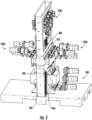
- the cooling structure includes vents as a coolant intake structure configured to receive air from lower portions of the first and second compartments, a fan assembly above the coolant intake structure and comprising at least one fan disposed between the first and second walls and configured to draw air through the coolant intake structure, the heatsink above the fan assembly and having a plurality of heat transfer surfaces that receive air from the fan assembly, and a duct above the heatsink that vertically exhausts air from the heatsink out of the enclosure.
- the apparatus may further include first and second contactors electrically coupled to respective ones of the first and second semiconductor static switches and disposed in respective ones of the first and second inner compartments below respective ones of the first and second semiconductor static switches.
- the apparatus may include at least one input bus assembly passing from at least one of the first and second outer compartments into at least one of the first and second inner compartments and electrically connected to at least one of the first and second contactors and first and second output bus assemblies electrically coupled to respective ones of the first and second semiconductor static switches and passing from respective ones of the first and second inner compartments to respective ones of the first and second outer compartments.
- First and second control circuit assemblies may be mounted on respective ones of the first and second vertical walls above the first and second semiconductor static switches.
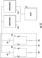
- FIG. 1 illustrates a power router apparatus 100 according to some embodiments.
- the apparatus 100 includes first and second static switch assemblies 120a, 120b, each of which includes antiparallel-connected silicon-controlled rectifiers. It will be appreciated that this arrangement represents an example implementation of a static switch, and that other semiconductor switches, such as power MOSFETs, may be used to provide a similar switch functionality.
- Respective first and second contactors 110a, 110b are coupled to the static switches 120a, 120b, and may be used, for example, to selectively provide an input to the static switches 120a, 120b, as explained below with reference to FIG. 12 . It will be appreciated that other circuit interruption devices, such as circuit breakers, may be used in place of the contactors 1 10a, 110b.
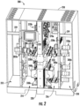
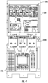
- FIGs. 2-9 illustrate a power router apparatus 200 having the electrical arrangement illustrated in FIG. 1 .
- the apparatus 200 includes a cuboid cabinet-like sheet metal enclosure 210, which has four compartments 212, 214, 216, 218 defined therein.
- Inner compartments 214, 216 house static switches 230a, 230b, contactors 240a, 240b and associated control boards 270a, 270b in a mirror image arrangement on respective sides of a columnar cooling structure 220 disposed between the inner compartments 214, 216.
- First and second output buses 250a, 250b are connected to respective ones of the static switches 230a, 230b and pass from the inner compartments 214, 216 into outer compartments 212, 218, where they may be connected to cables or other conductors.
- Current transformers 233 for monitoring currents in the output buses 250a, 250b may be housed within the inner compartments 214, 216.
- components housed in the inner compartments 214, 216 may be shielded from arc flashes or other potentially damaging events occurring in the outer compartments 212, 218, and potentially damaging events occurring on one side of the apparatus 200 may be isolated from components on the other side of the apparatus 200.
- exterior control cabling for components in the inner compartments 214, 216 may pass through the outer compartments 212, 218 via protected channels 219.
- the right side outer compartment 218 also houses a common input bus 260 that feeds the contactors 240a, 240b, and provides an enclosure for connection of cables or other conductors to the common input bus 260. It will be appreciated, however, that other input bus arrangements may be provided, such as those described below with reference to FIGs. 10 and 11 .
- FIG. 12 illustrates an exemplary application of a power router apparatus 100 as described herein.
- Converter modules 140a, 140b e.g., inverter modules
- Respective ones of the static switches 120a, 120b control respective outputs 130a, 130b.
- a third, un-switched output 130c may also be provided.
Landscapes
- Engineering & Computer Science (AREA)
- Microelectronics & Electronic Packaging (AREA)
- Physics & Mathematics (AREA)
- Thermal Sciences (AREA)
- Computer Hardware Design (AREA)
- General Engineering & Computer Science (AREA)
- Cooling Or The Like Of Electrical Apparatus (AREA)
Claims (7)
- Appareil (200) comprenant :une enceinte (210) comportant des premier et deuxième compartiments (214, 216) comportant des première et seconde parois opposées respectives ;une structure colonnaire de refroidissement (220) disposée entre les premier et deuxième compartiments (214, 216) et où est défini un passage réfrigérant conçu pour soutenir un flux de réfrigérant dans une direction parallèle aux première et seconde parois opposées ;un puits de chaleur (282) disposé dans le passage pour réfrigérant ; etdes premier et second commutateurs semiconducteurs (230a, 230b) disposés dans des compartiments respectifs parmi les premier et deuxième compartiments (214, 216) et couplés thermiquement aux premier et second côtés du puits de chaleur (282) pour que les premier et second commutateurs semiconducteurs (230a, 230b) soient refroidis par le flux de réfrigérant à travers le puits de chaleur (282), caractérisé en ce que la structure colonnaire de refroidissement (220) comprend en outre au moins un évent (310a, 310b) sur la première et/ou seconde paroi en une partie basse de la structure colonnaire de refroidissement (220) au-dessous du puits de chaleur (282) et conçu pour fournir du réfrigérant à partir de l'intérieur du premier et/ou du deuxième compartiments vers le passage de réfrigérant.
- Appareil (200) selon la revendication 1, dans lequel la structure colonnaire de refroidissement (220) comprend en outre au moins un ventilateur, disposé entre les première et seconde parois et conçu pour générer le flux de refroidissement.
- Appareil (200) selon la revendication 2, dans lequel la structure colonnaire de refroidissement comprend une pluralité de ventilateurs, disposés entre les première et seconde parois et conçus pour générer le flux de refroidissement.
- Appareil (200) selon la revendication 2, dans lequel le puits de chaleur (282) est positionné dans le passage pour réfrigérant de sorte qu'au moins une surface de transfert de chaleur reçoive le flux de réfrigérant à partir de l'au moins un ventilateur.
- Appareil (200) selon la revendication 4, dans lequel la structure de refroidissement comprend en outre un conduit conçu pour évacuer du réfrigérant reçu du puits de chaleur.
- Appareil (200) selon la revendication 1, comprenant en outre des premier et second contacteurs (240a, 240b) couplés électriquement aux commutateurs respectifs parmi les premier et second commutateurs semiconducteurs (230a, 230b) et disposés dans les commutateurs respectifs parmi les premier et deuxième compartiments (214, 216).
- Appareil (200) selon la revendication 6, dans lequel l'enceinte (210) comprend en outre un troisième compartiment (212) d'un côté du premier compartiment (214) opposé à un côté du premier compartiment (214) qui fait face au deuxième compartiment (216) et un quatrième compartiment (218) d'un côté du deuxième compartiment (216) opposé à un côté du deuxième compartiment (216) faisant face au premier compartiment (214) et dans lequel l'appareil (200) comprend en outre au moins un ensemble bus d'entrée (260 ; 260a, 260b) passant du premier et/ou du deuxième compartiment (214, 216) au troisième et/ou au quatrième compartiment (212, 218) et connecté électriquement au premier et/ou au second contacteur (240a, 240b).
Applications Claiming Priority (2)
| Application Number | Priority Date | Filing Date | Title |
|---|---|---|---|
| US201862614584P | 2018-01-08 | 2018-01-08 | |
| PCT/EP2019/025004 WO2019134900A1 (fr) | 2018-01-08 | 2019-01-08 | Appareil électrique à compartiments multiples avec ensemble de refroidissement partagé |
Publications (2)
| Publication Number | Publication Date |
|---|---|
| EP3738417A1 EP3738417A1 (fr) | 2020-11-18 |
| EP3738417B1 true EP3738417B1 (fr) | 2024-08-28 |
Family
ID=65041711
Family Applications (1)
| Application Number | Title | Priority Date | Filing Date |
|---|---|---|---|
| EP19701024.2A Active EP3738417B1 (fr) | 2018-01-08 | 2019-01-08 | Appareil électrique à compartiments multiples avec ensemble de refroidissement partagé |
Country Status (4)
| Country | Link |
|---|---|
| US (3) | US10617041B2 (fr) |
| EP (1) | EP3738417B1 (fr) |
| CN (1) | CN111684870A (fr) |
| WO (1) | WO2019134900A1 (fr) |
Families Citing this family (3)
| Publication number | Priority date | Publication date | Assignee | Title |
|---|---|---|---|---|
| DE102018208439A1 (de) * | 2018-05-29 | 2019-12-05 | Phoenix Contact Gmbh & Co. Kg | Flexibler Schutzschalter |
| US11070140B2 (en) * | 2018-10-25 | 2021-07-20 | Eaton Intelligent Power Limited | Low inductance bus assembly and power converter apparatus including the same |
| US20240155803A1 (en) * | 2022-11-08 | 2024-05-09 | Abb Schweiz Ag | Electrical System and Electrical Apparatus for Static Transfer Switch Power and Cooling |
Citations (1)
| Publication number | Priority date | Publication date | Assignee | Title |
|---|---|---|---|---|
| EP2704546A2 (fr) * | 2012-08-30 | 2014-03-05 | Delta Electronics, Inc. | Système de dissipation thermique pour armoire de haute puissance et système de compensation de var statique |
Family Cites Families (8)
| Publication number | Priority date | Publication date | Assignee | Title |
|---|---|---|---|---|
| US4691274A (en) * | 1986-04-29 | 1987-09-01 | Modular Power Corporation | Modular electronic power supply |
| US5481429A (en) * | 1991-03-18 | 1996-01-02 | Asea Brown Boveri Ab | Distribution of cooling air in switchgear cubicles |
| US6046921A (en) * | 1996-08-27 | 2000-04-04 | Tracewell; Larry L. | Modular power supply |
| US7447022B2 (en) * | 2006-08-09 | 2008-11-04 | Hewlett-Packard Development Company, L.P. | Rack-mount equipment bay cooling heat exchanger |
| DE102010017168B4 (de) | 2010-05-31 | 2014-04-10 | Refusol Gmbh | Anordnung mitVerfahren zum Kühlen Wärme erzeugender Bauteile |
| KR101189451B1 (ko) | 2010-12-24 | 2012-10-09 | 엘지전자 주식회사 | 인버터 스택 |
| DE102011001786A1 (de) * | 2011-04-04 | 2012-10-04 | Woodward Kempen Gmbh | Schaltschrankanordnung einer Vorrichtung zur Erzeugung elektrischer Energie |
| DE102015115421A1 (de) | 2015-09-14 | 2017-03-16 | Sma Solar Technology Ag | Wechselrichter mit einem mehrteiligen Gehäuse und innenliegendem Kühlluftkanal |
-
2019
- 2019-01-07 US US16/241,471 patent/US10617041B2/en active Active
- 2019-01-08 EP EP19701024.2A patent/EP3738417B1/fr active Active
- 2019-01-08 WO PCT/EP2019/025004 patent/WO2019134900A1/fr not_active Ceased
- 2019-01-08 CN CN201980012137.XA patent/CN111684870A/zh active Pending
-
2020
- 2020-04-06 US US16/841,624 patent/US11284541B2/en active Active
-
2022
- 2022-03-21 US US17/655,647 patent/US11864358B2/en active Active
Patent Citations (1)
| Publication number | Priority date | Publication date | Assignee | Title |
|---|---|---|---|---|
| EP2704546A2 (fr) * | 2012-08-30 | 2014-03-05 | Delta Electronics, Inc. | Système de dissipation thermique pour armoire de haute puissance et système de compensation de var statique |
Also Published As
| Publication number | Publication date |
|---|---|
| US11284541B2 (en) | 2022-03-22 |
| US20190215991A1 (en) | 2019-07-11 |
| US11864358B2 (en) | 2024-01-02 |
| WO2019134900A1 (fr) | 2019-07-11 |
| US20220210951A1 (en) | 2022-06-30 |
| US20200404810A1 (en) | 2020-12-24 |
| EP3738417A1 (fr) | 2020-11-18 |
| CN111684870A (zh) | 2020-09-18 |
| US10617041B2 (en) | 2020-04-07 |
Similar Documents
| Publication | Publication Date | Title |
|---|---|---|
| US11864358B2 (en) | Multi-compartment electrical apparatus with shared cooling assembly | |
| US8289709B2 (en) | Inverter system | |
| US8575479B2 (en) | Providing a transformer for an inverter | |
| JP3300566B2 (ja) | パワーモジュール及び電力変換装置 | |
| US20150357798A1 (en) | Integrated bus duct and ups systems | |
| US20240090184A1 (en) | Power distribution cabinet and direct current power distribution system for energy storage | |
| CN217428000U (zh) | 逆变器及逆变系统 | |
| JP2010098865A (ja) | 電力変換装置盤 | |
| US10854861B2 (en) | Mounting rack for a power electronics installation and installation comprising a mounting rack of this kind | |
| CA2280067C (fr) | Configuration de modules electroniques de puissance | |
| JP7513063B2 (ja) | 無停電電源装置用制御装置 | |
| JP3481846B2 (ja) | 電力変換装置 | |
| CN105703644A (zh) | 功率转换装置 | |
| US10819089B2 (en) | Heated electrical distribution system | |
| US6909614B2 (en) | Power backplane for power electronic devices | |
| JP7203237B2 (ja) | モジュールied | |
| EP4369877A2 (fr) | Système électrique et appareil électrique pour le refroidissement et la puissance d'un commutateur de transfert statique | |
| CN209709697U (zh) | 光伏并网逆变器及其交流柜 | |
| CA2280068A1 (fr) | Dispositif de ventilation de systeme d'alimentation electronique | |
| EP1243059A1 (fr) | Commutateur electrique avec dispositif destine a refroidir les composants internes | |
| CS237060B1 (cs) | Uspořádání funkčních prvků elektronického přístroje | |
| CS241691B1 (cs) | Konstrukce polovodičového měniče s kapalinovým chlazením |
Legal Events
| Date | Code | Title | Description |
|---|---|---|---|
| STAA | Information on the status of an ep patent application or granted ep patent |
Free format text: STATUS: UNKNOWN |
|
| STAA | Information on the status of an ep patent application or granted ep patent |
Free format text: STATUS: THE INTERNATIONAL PUBLICATION HAS BEEN MADE |
|
| PUAI | Public reference made under article 153(3) epc to a published international application that has entered the european phase |
Free format text: ORIGINAL CODE: 0009012 |
|
| STAA | Information on the status of an ep patent application or granted ep patent |
Free format text: STATUS: REQUEST FOR EXAMINATION WAS MADE |
|
| 17P | Request for examination filed |
Effective date: 20200730 |
|
| AK | Designated contracting states |
Kind code of ref document: A1 Designated state(s): AL AT BE BG CH CY CZ DE DK EE ES FI FR GB GR HR HU IE IS IT LI LT LU LV MC MK MT NL NO PL PT RO RS SE SI SK SM TR |
|
| AX | Request for extension of the european patent |
Extension state: BA ME |
|
| DAV | Request for validation of the european patent (deleted) | ||
| DAX | Request for extension of the european patent (deleted) | ||
| STAA | Information on the status of an ep patent application or granted ep patent |
Free format text: STATUS: EXAMINATION IS IN PROGRESS |
|
| 17Q | First examination report despatched |
Effective date: 20220614 |
|
| P01 | Opt-out of the competence of the unified patent court (upc) registered |
Effective date: 20230521 |
|
| GRAP | Despatch of communication of intention to grant a patent |
Free format text: ORIGINAL CODE: EPIDOSNIGR1 |
|
| STAA | Information on the status of an ep patent application or granted ep patent |
Free format text: STATUS: GRANT OF PATENT IS INTENDED |
|
| RIC1 | Information provided on ipc code assigned before grant |
Ipc: H05K 7/14 20060101ALI20240305BHEP Ipc: H05K 7/20 20060101AFI20240305BHEP |
|
| INTG | Intention to grant announced |
Effective date: 20240409 |
|
| GRAS | Grant fee paid |
Free format text: ORIGINAL CODE: EPIDOSNIGR3 |
|
| GRAA | (expected) grant |
Free format text: ORIGINAL CODE: 0009210 |
|
| STAA | Information on the status of an ep patent application or granted ep patent |
Free format text: STATUS: THE PATENT HAS BEEN GRANTED |
|
| AK | Designated contracting states |
Kind code of ref document: B1 Designated state(s): AL AT BE BG CH CY CZ DE DK EE ES FI FR GB GR HR HU IE IS IT LI LT LU LV MC MK MT NL NO PL PT RO RS SE SI SK SM TR |
|
| REG | Reference to a national code |
Ref country code: GB Ref legal event code: FG4D |
|
| REG | Reference to a national code |
Ref country code: CH Ref legal event code: EP |
|
| REG | Reference to a national code |
Ref country code: DE Ref legal event code: R096 Ref document number: 602019057815 Country of ref document: DE |
|
| REG | Reference to a national code |
Ref country code: IE Ref legal event code: FG4D |
|
| REG | Reference to a national code |
Ref country code: LT Ref legal event code: MG9D |
|
| PG25 | Lapsed in a contracting state [announced via postgrant information from national office to epo] |
Ref country code: NO Free format text: LAPSE BECAUSE OF FAILURE TO SUBMIT A TRANSLATION OF THE DESCRIPTION OR TO PAY THE FEE WITHIN THE PRESCRIBED TIME-LIMIT Effective date: 20241128 |
|
| REG | Reference to a national code |
Ref country code: AT Ref legal event code: MK05 Ref document number: 1719324 Country of ref document: AT Kind code of ref document: T Effective date: 20240828 |
|
| PG25 | Lapsed in a contracting state [announced via postgrant information from national office to epo] |
Ref country code: NL Free format text: LAPSE BECAUSE OF FAILURE TO SUBMIT A TRANSLATION OF THE DESCRIPTION OR TO PAY THE FEE WITHIN THE PRESCRIBED TIME-LIMIT Effective date: 20240828 Ref country code: PT Free format text: LAPSE BECAUSE OF FAILURE TO SUBMIT A TRANSLATION OF THE DESCRIPTION OR TO PAY THE FEE WITHIN THE PRESCRIBED TIME-LIMIT Effective date: 20241230 Ref country code: GR Free format text: LAPSE BECAUSE OF FAILURE TO SUBMIT A TRANSLATION OF THE DESCRIPTION OR TO PAY THE FEE WITHIN THE PRESCRIBED TIME-LIMIT Effective date: 20241129 Ref country code: FI Free format text: LAPSE BECAUSE OF FAILURE TO SUBMIT A TRANSLATION OF THE DESCRIPTION OR TO PAY THE FEE WITHIN THE PRESCRIBED TIME-LIMIT Effective date: 20240828 Ref country code: PL Free format text: LAPSE BECAUSE OF FAILURE TO SUBMIT A TRANSLATION OF THE DESCRIPTION OR TO PAY THE FEE WITHIN THE PRESCRIBED TIME-LIMIT Effective date: 20240828 |
|
| PG25 | Lapsed in a contracting state [announced via postgrant information from national office to epo] |
Ref country code: BG Free format text: LAPSE BECAUSE OF FAILURE TO SUBMIT A TRANSLATION OF THE DESCRIPTION OR TO PAY THE FEE WITHIN THE PRESCRIBED TIME-LIMIT Effective date: 20240828 |
|
| PG25 | Lapsed in a contracting state [announced via postgrant information from national office to epo] |
Ref country code: LV Free format text: LAPSE BECAUSE OF FAILURE TO SUBMIT A TRANSLATION OF THE DESCRIPTION OR TO PAY THE FEE WITHIN THE PRESCRIBED TIME-LIMIT Effective date: 20240828 |
|
| REG | Reference to a national code |
Ref country code: NL Ref legal event code: MP Effective date: 20240828 |
|
| PG25 | Lapsed in a contracting state [announced via postgrant information from national office to epo] |
Ref country code: IS Free format text: LAPSE BECAUSE OF FAILURE TO SUBMIT A TRANSLATION OF THE DESCRIPTION OR TO PAY THE FEE WITHIN THE PRESCRIBED TIME-LIMIT Effective date: 20241228 Ref country code: AT Free format text: LAPSE BECAUSE OF FAILURE TO SUBMIT A TRANSLATION OF THE DESCRIPTION OR TO PAY THE FEE WITHIN THE PRESCRIBED TIME-LIMIT Effective date: 20240828 |
|
| PG25 | Lapsed in a contracting state [announced via postgrant information from national office to epo] |
Ref country code: HR Free format text: LAPSE BECAUSE OF FAILURE TO SUBMIT A TRANSLATION OF THE DESCRIPTION OR TO PAY THE FEE WITHIN THE PRESCRIBED TIME-LIMIT Effective date: 20240828 |
|
| PG25 | Lapsed in a contracting state [announced via postgrant information from national office to epo] |
Ref country code: ES Free format text: LAPSE BECAUSE OF FAILURE TO SUBMIT A TRANSLATION OF THE DESCRIPTION OR TO PAY THE FEE WITHIN THE PRESCRIBED TIME-LIMIT Effective date: 20240828 Ref country code: RS Free format text: LAPSE BECAUSE OF FAILURE TO SUBMIT A TRANSLATION OF THE DESCRIPTION OR TO PAY THE FEE WITHIN THE PRESCRIBED TIME-LIMIT Effective date: 20241128 |
|
| PG25 | Lapsed in a contracting state [announced via postgrant information from national office to epo] |
Ref country code: RS Free format text: LAPSE BECAUSE OF FAILURE TO SUBMIT A TRANSLATION OF THE DESCRIPTION OR TO PAY THE FEE WITHIN THE PRESCRIBED TIME-LIMIT Effective date: 20241128 Ref country code: PT Free format text: LAPSE BECAUSE OF FAILURE TO SUBMIT A TRANSLATION OF THE DESCRIPTION OR TO PAY THE FEE WITHIN THE PRESCRIBED TIME-LIMIT Effective date: 20241230 Ref country code: PL Free format text: LAPSE BECAUSE OF FAILURE TO SUBMIT A TRANSLATION OF THE DESCRIPTION OR TO PAY THE FEE WITHIN THE PRESCRIBED TIME-LIMIT Effective date: 20240828 Ref country code: NO Free format text: LAPSE BECAUSE OF FAILURE TO SUBMIT A TRANSLATION OF THE DESCRIPTION OR TO PAY THE FEE WITHIN THE PRESCRIBED TIME-LIMIT Effective date: 20241128 Ref country code: NL Free format text: LAPSE BECAUSE OF FAILURE TO SUBMIT A TRANSLATION OF THE DESCRIPTION OR TO PAY THE FEE WITHIN THE PRESCRIBED TIME-LIMIT Effective date: 20240828 Ref country code: LV Free format text: LAPSE BECAUSE OF FAILURE TO SUBMIT A TRANSLATION OF THE DESCRIPTION OR TO PAY THE FEE WITHIN THE PRESCRIBED TIME-LIMIT Effective date: 20240828 Ref country code: IS Free format text: LAPSE BECAUSE OF FAILURE TO SUBMIT A TRANSLATION OF THE DESCRIPTION OR TO PAY THE FEE WITHIN THE PRESCRIBED TIME-LIMIT Effective date: 20241228 Ref country code: HR Free format text: LAPSE BECAUSE OF FAILURE TO SUBMIT A TRANSLATION OF THE DESCRIPTION OR TO PAY THE FEE WITHIN THE PRESCRIBED TIME-LIMIT Effective date: 20240828 Ref country code: GR Free format text: LAPSE BECAUSE OF FAILURE TO SUBMIT A TRANSLATION OF THE DESCRIPTION OR TO PAY THE FEE WITHIN THE PRESCRIBED TIME-LIMIT Effective date: 20241129 Ref country code: FI Free format text: LAPSE BECAUSE OF FAILURE TO SUBMIT A TRANSLATION OF THE DESCRIPTION OR TO PAY THE FEE WITHIN THE PRESCRIBED TIME-LIMIT Effective date: 20240828 Ref country code: ES Free format text: LAPSE BECAUSE OF FAILURE TO SUBMIT A TRANSLATION OF THE DESCRIPTION OR TO PAY THE FEE WITHIN THE PRESCRIBED TIME-LIMIT Effective date: 20240828 Ref country code: BG Free format text: LAPSE BECAUSE OF FAILURE TO SUBMIT A TRANSLATION OF THE DESCRIPTION OR TO PAY THE FEE WITHIN THE PRESCRIBED TIME-LIMIT Effective date: 20240828 Ref country code: AT Free format text: LAPSE BECAUSE OF FAILURE TO SUBMIT A TRANSLATION OF THE DESCRIPTION OR TO PAY THE FEE WITHIN THE PRESCRIBED TIME-LIMIT Effective date: 20240828 |
|
| PG25 | Lapsed in a contracting state [announced via postgrant information from national office to epo] |
Ref country code: SM Free format text: LAPSE BECAUSE OF FAILURE TO SUBMIT A TRANSLATION OF THE DESCRIPTION OR TO PAY THE FEE WITHIN THE PRESCRIBED TIME-LIMIT Effective date: 20240828 Ref country code: RO Free format text: LAPSE BECAUSE OF FAILURE TO SUBMIT A TRANSLATION OF THE DESCRIPTION OR TO PAY THE FEE WITHIN THE PRESCRIBED TIME-LIMIT Effective date: 20240828 Ref country code: DK Free format text: LAPSE BECAUSE OF FAILURE TO SUBMIT A TRANSLATION OF THE DESCRIPTION OR TO PAY THE FEE WITHIN THE PRESCRIBED TIME-LIMIT Effective date: 20240828 |
|
| PG25 | Lapsed in a contracting state [announced via postgrant information from national office to epo] |
Ref country code: EE Free format text: LAPSE BECAUSE OF FAILURE TO SUBMIT A TRANSLATION OF THE DESCRIPTION OR TO PAY THE FEE WITHIN THE PRESCRIBED TIME-LIMIT Effective date: 20240828 |
|
| PG25 | Lapsed in a contracting state [announced via postgrant information from national office to epo] |
Ref country code: CZ Free format text: LAPSE BECAUSE OF FAILURE TO SUBMIT A TRANSLATION OF THE DESCRIPTION OR TO PAY THE FEE WITHIN THE PRESCRIBED TIME-LIMIT Effective date: 20240828 |
|
| PG25 | Lapsed in a contracting state [announced via postgrant information from national office to epo] |
Ref country code: SK Free format text: LAPSE BECAUSE OF FAILURE TO SUBMIT A TRANSLATION OF THE DESCRIPTION OR TO PAY THE FEE WITHIN THE PRESCRIBED TIME-LIMIT Effective date: 20240828 Ref country code: IT Free format text: LAPSE BECAUSE OF FAILURE TO SUBMIT A TRANSLATION OF THE DESCRIPTION OR TO PAY THE FEE WITHIN THE PRESCRIBED TIME-LIMIT Effective date: 20240828 |
|
| REG | Reference to a national code |
Ref country code: DE Ref legal event code: R097 Ref document number: 602019057815 Country of ref document: DE |
|
| PLBE | No opposition filed within time limit |
Free format text: ORIGINAL CODE: 0009261 |
|
| STAA | Information on the status of an ep patent application or granted ep patent |
Free format text: STATUS: NO OPPOSITION FILED WITHIN TIME LIMIT |
|
| 26N | No opposition filed |
Effective date: 20250530 |
|
| REG | Reference to a national code |
Ref country code: CH Ref legal event code: PL |
|
| PG25 | Lapsed in a contracting state [announced via postgrant information from national office to epo] |
Ref country code: SE Free format text: LAPSE BECAUSE OF FAILURE TO SUBMIT A TRANSLATION OF THE DESCRIPTION OR TO PAY THE FEE WITHIN THE PRESCRIBED TIME-LIMIT Effective date: 20240828 |
|
| PG25 | Lapsed in a contracting state [announced via postgrant information from national office to epo] |
Ref country code: MC Free format text: LAPSE BECAUSE OF FAILURE TO SUBMIT A TRANSLATION OF THE DESCRIPTION OR TO PAY THE FEE WITHIN THE PRESCRIBED TIME-LIMIT Effective date: 20240828 Ref country code: LU Free format text: LAPSE BECAUSE OF NON-PAYMENT OF DUE FEES Effective date: 20250108 |
|
| PG25 | Lapsed in a contracting state [announced via postgrant information from national office to epo] |
Ref country code: BE Free format text: LAPSE BECAUSE OF NON-PAYMENT OF DUE FEES Effective date: 20250131 |
|
| PG25 | Lapsed in a contracting state [announced via postgrant information from national office to epo] |
Ref country code: CH Free format text: LAPSE BECAUSE OF NON-PAYMENT OF DUE FEES Effective date: 20250131 |
|
| REG | Reference to a national code |
Ref country code: BE Ref legal event code: MM Effective date: 20250131 |
|
| PGFP | Annual fee paid to national office [announced via postgrant information from national office to epo] |
Ref country code: GB Payment date: 20251219 Year of fee payment: 8 |
|
| PGFP | Annual fee paid to national office [announced via postgrant information from national office to epo] |
Ref country code: FR Payment date: 20251217 Year of fee payment: 8 |
|
| PG25 | Lapsed in a contracting state [announced via postgrant information from national office to epo] |
Ref country code: IE Free format text: LAPSE BECAUSE OF NON-PAYMENT OF DUE FEES Effective date: 20250108 |
|
| PGFP | Annual fee paid to national office [announced via postgrant information from national office to epo] |
Ref country code: DE Payment date: 20251217 Year of fee payment: 8 |