EP3738455B1 - Externe einheit für eine inhalationskomponentenerzeugungsvorrichtung, inhalationskomponentenerzeugungssystem, verfahren zur steuerung einer externen einheit für eine inhalationskomponentenerzeugungsvorrichtung und programm - Google Patents
Externe einheit für eine inhalationskomponentenerzeugungsvorrichtung, inhalationskomponentenerzeugungssystem, verfahren zur steuerung einer externen einheit für eine inhalationskomponentenerzeugungsvorrichtung und programm Download PDFInfo
- Publication number
- EP3738455B1 EP3738455B1 EP18903879.7A EP18903879A EP3738455B1 EP 3738455 B1 EP3738455 B1 EP 3738455B1 EP 18903879 A EP18903879 A EP 18903879A EP 3738455 B1 EP3738455 B1 EP 3738455B1
- Authority
- EP
- European Patent Office
- Prior art keywords
- power supply
- supply unit
- resistor
- control part
- charger
- Prior art date
- Legal status (The legal status is an assumption and is not a legal conclusion. Google has not performed a legal analysis and makes no representation as to the accuracy of the status listed.)
- Active
Links
Images


Classifications
-
- A—HUMAN NECESSITIES
- A24—TOBACCO; CIGARS; CIGARETTES; SIMULATED SMOKING DEVICES; SMOKERS' REQUISITES
- A24F—SMOKERS' REQUISITES; MATCH BOXES; SIMULATED SMOKING DEVICES
- A24F40/00—Electrically operated smoking devices; Component parts thereof; Manufacture thereof; Maintenance or testing thereof; Charging means specially adapted therefor
- A24F40/50—Control or monitoring
- A24F40/51—Arrangement of sensors
-
- A—HUMAN NECESSITIES
- A24—TOBACCO; CIGARS; CIGARETTES; SIMULATED SMOKING DEVICES; SMOKERS' REQUISITES
- A24F—SMOKERS' REQUISITES; MATCH BOXES; SIMULATED SMOKING DEVICES
- A24F40/00—Electrically operated smoking devices; Component parts thereof; Manufacture thereof; Maintenance or testing thereof; Charging means specially adapted therefor
- A24F40/60—Devices with integrated user interfaces
-
- A—HUMAN NECESSITIES
- A24—TOBACCO; CIGARS; CIGARETTES; SIMULATED SMOKING DEVICES; SMOKERS' REQUISITES
- A24F—SMOKERS' REQUISITES; MATCH BOXES; SIMULATED SMOKING DEVICES
- A24F40/00—Electrically operated smoking devices; Component parts thereof; Manufacture thereof; Maintenance or testing thereof; Charging means specially adapted therefor
- A24F40/90—Arrangements or methods specially adapted for charging batteries thereof
-
- H—ELECTRICITY
- H02—GENERATION; CONVERSION OR DISTRIBUTION OF ELECTRIC POWER
- H02J—ELECTRIC POWER NETWORKS; CIRCUIT ARRANGEMENTS OR SYSTEMS FOR SUPPLYING OR DISTRIBUTING ELECTRIC POWER; SYSTEMS FOR STORING ELECTRIC ENERGY
- H02J7/00—Circuit arrangements for charging or discharging batteries or for supplying loads from batteries
- H02J7/40—Circuit arrangements for charging or discharging batteries or for supplying loads from batteries characterised by the exchange of charge or discharge related data
- H02J7/443—Circuit arrangements for charging or discharging batteries or for supplying loads from batteries characterised by the exchange of charge or discharge related data using passive battery identification means, e.g. resistors or capacitors
-
- H—ELECTRICITY
- H02—GENERATION; CONVERSION OR DISTRIBUTION OF ELECTRIC POWER
- H02J—ELECTRIC POWER NETWORKS; CIRCUIT ARRANGEMENTS OR SYSTEMS FOR SUPPLYING OR DISTRIBUTING ELECTRIC POWER; SYSTEMS FOR STORING ELECTRIC ENERGY
- H02J7/00—Circuit arrangements for charging or discharging batteries or for supplying loads from batteries
- H02J7/40—Circuit arrangements for charging or discharging batteries or for supplying loads from batteries characterised by the exchange of charge or discharge related data
- H02J7/47—Arrangements for checking compatibility or authentication between one component, e.g. a battery or a battery charger, and another component, e.g. a power source
-
- H—ELECTRICITY
- H02—GENERATION; CONVERSION OR DISTRIBUTION OF ELECTRIC POWER
- H02J—ELECTRIC POWER NETWORKS; CIRCUIT ARRANGEMENTS OR SYSTEMS FOR SUPPLYING OR DISTRIBUTING ELECTRIC POWER; SYSTEMS FOR STORING ELECTRIC ENERGY
- H02J7/00—Circuit arrangements for charging or discharging batteries or for supplying loads from batteries
- H02J7/60—Circuit arrangements for charging or discharging batteries or for supplying loads from batteries including safety or protection arrangements
- H02J7/685—Circuit arrangements for charging or discharging batteries or for supplying loads from batteries including safety or protection arrangements using connection detecting circuits
-
- H—ELECTRICITY
- H02—GENERATION; CONVERSION OR DISTRIBUTION OF ELECTRIC POWER
- H02J—ELECTRIC POWER NETWORKS; CIRCUIT ARRANGEMENTS OR SYSTEMS FOR SUPPLYING OR DISTRIBUTING ELECTRIC POWER; SYSTEMS FOR STORING ELECTRIC ENERGY
- H02J7/00—Circuit arrangements for charging or discharging batteries or for supplying loads from batteries
- H02J7/70—Circuit arrangements for charging or discharging batteries or for supplying loads from batteries characterised by the mechanical construction
-
- H—ELECTRICITY
- H02—GENERATION; CONVERSION OR DISTRIBUTION OF ELECTRIC POWER
- H02J—ELECTRIC POWER NETWORKS; CIRCUIT ARRANGEMENTS OR SYSTEMS FOR SUPPLYING OR DISTRIBUTING ELECTRIC POWER; SYSTEMS FOR STORING ELECTRIC ENERGY
- H02J7/00—Circuit arrangements for charging or discharging batteries or for supplying loads from batteries
- H02J7/80—Circuit arrangements for charging or discharging batteries or for supplying loads from batteries including monitoring or indicating arrangements
-
- H—ELECTRICITY
- H02—GENERATION; CONVERSION OR DISTRIBUTION OF ELECTRIC POWER
- H02J—ELECTRIC POWER NETWORKS; CIRCUIT ARRANGEMENTS OR SYSTEMS FOR SUPPLYING OR DISTRIBUTING ELECTRIC POWER; SYSTEMS FOR STORING ELECTRIC ENERGY
- H02J7/00—Circuit arrangements for charging or discharging batteries or for supplying loads from batteries
- H02J7/90—Regulation of charging or discharging current or voltage
- H02J7/92—Regulation of charging or discharging current or voltage with prioritisation of loads or sources
-
- H—ELECTRICITY
- H02—GENERATION; CONVERSION OR DISTRIBUTION OF ELECTRIC POWER
- H02J—ELECTRIC POWER NETWORKS; CIRCUIT ARRANGEMENTS OR SYSTEMS FOR SUPPLYING OR DISTRIBUTING ELECTRIC POWER; SYSTEMS FOR STORING ELECTRIC ENERGY
- H02J7/00—Circuit arrangements for charging or discharging batteries or for supplying loads from batteries
- H02J7/90—Regulation of charging or discharging current or voltage
- H02J7/933—Regulation of charging or discharging current or voltage the cycle being controlled or terminated in response to electric parameters
-
- H—ELECTRICITY
- H02—GENERATION; CONVERSION OR DISTRIBUTION OF ELECTRIC POWER
- H02J—ELECTRIC POWER NETWORKS; CIRCUIT ARRANGEMENTS OR SYSTEMS FOR SUPPLYING OR DISTRIBUTING ELECTRIC POWER; SYSTEMS FOR STORING ELECTRIC ENERGY
- H02J7/00—Circuit arrangements for charging or discharging batteries or for supplying loads from batteries
- H02J7/90—Regulation of charging or discharging current or voltage
- H02J7/94—Regulation of charging or discharging current or voltage in response to battery current
-
- H—ELECTRICITY
- H02—GENERATION; CONVERSION OR DISTRIBUTION OF ELECTRIC POWER
- H02J—ELECTRIC POWER NETWORKS; CIRCUIT ARRANGEMENTS OR SYSTEMS FOR SUPPLYING OR DISTRIBUTING ELECTRIC POWER; SYSTEMS FOR STORING ELECTRIC ENERGY
- H02J7/00—Circuit arrangements for charging or discharging batteries or for supplying loads from batteries
- H02J7/90—Regulation of charging or discharging current or voltage
- H02J7/96—Regulation of charging or discharging current or voltage in response to battery voltage
-
- A—HUMAN NECESSITIES
- A24—TOBACCO; CIGARS; CIGARETTES; SIMULATED SMOKING DEVICES; SMOKERS' REQUISITES
- A24F—SMOKERS' REQUISITES; MATCH BOXES; SIMULATED SMOKING DEVICES
- A24F40/00—Electrically operated smoking devices; Component parts thereof; Manufacture thereof; Maintenance or testing thereof; Charging means specially adapted therefor
- A24F40/10—Devices using liquid inhalable precursors
-
- H—ELECTRICITY
- H02—GENERATION; CONVERSION OR DISTRIBUTION OF ELECTRIC POWER
- H02J—ELECTRIC POWER NETWORKS; CIRCUIT ARRANGEMENTS OR SYSTEMS FOR SUPPLYING OR DISTRIBUTING ELECTRIC POWER; SYSTEMS FOR STORING ELECTRIC ENERGY
- H02J2105/00—Networks for supplying or distributing electric power characterised by their spatial reach or by the load
- H02J2105/40—Networks for supplying or distributing electric power characterised by their spatial reach or by the load characterised by the loads connecting to the networks or being supplied by the networks
- H02J2105/44—Portable electronic devices
-
- H—ELECTRICITY
- H02—GENERATION; CONVERSION OR DISTRIBUTION OF ELECTRIC POWER
- H02J—ELECTRIC POWER NETWORKS; CIRCUIT ARRANGEMENTS OR SYSTEMS FOR SUPPLYING OR DISTRIBUTING ELECTRIC POWER; SYSTEMS FOR STORING ELECTRIC ENERGY
- H02J7/00—Circuit arrangements for charging or discharging batteries or for supplying loads from batteries
- H02J7/80—Circuit arrangements for charging or discharging batteries or for supplying loads from batteries including monitoring or indicating arrangements
- H02J7/82—Control of state of charge [SOC]
- H02J7/825—Detection of fully charged condition
-
- Y—GENERAL TAGGING OF NEW TECHNOLOGICAL DEVELOPMENTS; GENERAL TAGGING OF CROSS-SECTIONAL TECHNOLOGIES SPANNING OVER SEVERAL SECTIONS OF THE IPC; TECHNICAL SUBJECTS COVERED BY FORMER USPC CROSS-REFERENCE ART COLLECTIONS [XRACs] AND DIGESTS
- Y02—TECHNOLOGIES OR APPLICATIONS FOR MITIGATION OR ADAPTATION AGAINST CLIMATE CHANGE
- Y02E—REDUCTION OF GREENHOUSE GAS [GHG] EMISSIONS, RELATED TO ENERGY GENERATION, TRANSMISSION OR DISTRIBUTION
- Y02E60/00—Enabling technologies; Technologies with a potential or indirect contribution to GHG emissions mitigation
- Y02E60/10—Energy storage using batteries
Definitions
- the present invention relates to an inhalation component generation system.
- an inhalation component generation device (an electronic cigarette or heated tobacco) used for tasting an inhalation component generated by vaporizing or atomizing a flavor source such as tobacco or an aerosol source with a load such as a heater (PTL 1 to PTL 3).
- Such an inhalation component generation device includes a load that vaporizes or atomizes a flavor source and/or an aerosol source, a power supply that supplies electric power to the load, and a control unit that controls the charge and discharge of the power supply and the load. Since the power supply that supplies the electric power to the load is formed by a secondary battery or the like, the power supply can be charged by a charger.
- PTL 1 and PTL 2 each disclose that a charging mode is selected according to a current and a voltage during the charging process.
- PTL 3 discloses that a charging mode is changed by communication between a battery unit having a power supply and a charger.
- PTL 4 to PTL 6 each disclose a technique relating to a change of a charging mode in a technical field different from that of an inhalation component generation device.
- US2016345627A1 relates to an electronic cigarette identification device comprising an electronic cigarette and an electronic cigarette case, wherein the electronic cigarette comprises an identification information generation module, and the electronic cigarette case comprises a power supply battery, a microprocessor, and an identification information receiving module; the microprocessor is connected to the power supply battery and the identification information receiving module; the identification information generation module outputs an identification information to the identification information receiving module by means of wired or wireless transmission; the identification information receiving module receives, converts and sends the identification information to the microprocessor; the microprocessor identifies whether the electronic cigarette case and the electronic cigarette match.
- US 2008/0238361 A1 discloses a method for charging a rechargeable battery that includes at least one rechargeable electrochemical cell, including measuring at least one electrical characteristic of the battery, and determining a charging current to be applied to the battery based on the at least one measured electrical characteristic.
- WO 2016/119626 A1 discloses an electronic smoking apparatus comprising control circuitry, driving circuitry, charging circuitry, excitation element, a flavoured source and a battery, the electronic smoking apparatus being operable in a smoking mode or a charging mode, and wherein the electronic smoking apparatus is detachable into a first module and a second module.
- the design of a device such as a power supply unit of an inhalation component generation device may be changed from various perspectives.
- the power supply unit after the design change may be configured to be connectable to an external unit that is the same as the external unit to which the power supply unit before the design change is connected, in view of ensuring compatibility and sharing components.
- the external unit cannot necessarily perform an optimal control for various types of external units.
- the external unit cannot necessarily perform an optimal control for various types of power supply units, when the design of the external unit for an inhalation component generation device is changed from various perspectives.
- An external unit for an inhalation component generation device includes a connection part that is electrically connectable to a power supply unit of the inhalation component generation device, a sensor that is capable of outputting an output value related to an electrical resistance value of a resistor provided in the power supply unit, and a first control part that is configured to determine, based on the output value, whether to change a predetermined control with respect to the power supply unit connected to the connection part or whether to perform the predetermined control.
- An inhalation component generation system includes the external unit for an inhalation component generation device according to the above-described aspect, and the power supply unit.
- a method of controlling a power supply unit of an inhalation component generation system includes the steps of acquiring an output value related to an electrical resistance value of a resistor provided in the power supply unit by the external unit, and determining whether to change a predetermined control with respect to the power supply unit electrically connected to the external unit or whether to perform the predetermined control, based on the output value.
- the external unit can distinguish the type of the power supply unit or the power supply in the power supply unit, using the value related to the electrical resistance value of the resistor in the power supply unit. That is, the external unit can distinguish the type of the power supply unit or the power supply without communicating with the power supply unit, by changing the electrical resistance value of the resistor to be output according to a different type of power supply unit or power supply. Furthermore, the external unit can distinguish the type of the power supply unit or the power supply without being provided with a memory that stores, in the power supply unit, information according to the type of the power supply unit or the power supply. Accordingly, the external unit can perform an optimal control for the power supply unit according to the type of the power supply unit or the power supply.
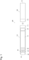
- Fig. 1 is a schematic diagram of an inhalation component generation device according to one embodiment.
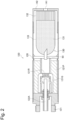
- Fig. 2 is a schematic diagram of an atomizing unit according to one embodiment.
- Fig. 3 is a block diagram of the inhalation component generation device.
- Fig. 4 is a diagram illustrating an electrical circuit of the power supply unit.
- Fig. 5 is a diagram illustrating an electrical circuit of the inhalation component generation device including the power supply unit and the atomizing unit.
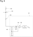
- Fig. 6 is a diagram illustrating an example of a configuration of a detecting part that detects a voltage drop amount of a second resistor in the power supply unit.
- An inhalation component generation device 100 may be a non-combustion-type flavor inhaler for inhaling an inhalation component (an inhaling flavor component) without combustion.
- the inhalation component generation device 100 may extend along a direction from a non-inhalation port end E2 toward an inhalation port end E1.
- the inhalation component generation device 100 may include one end E1 having an inhalation port 141 for inhaling an inhalation component and the other end E2 opposite to the inhalation port 141.
- the inhalation component generation device 100 may include a power supply unit 110 and an atomizing unit 120.
- the atomizing unit 120 may be configured to be detachably attached to the power supply unit 110 through connection parts 111 and 121.
- a load 121R (described later) in the atomizing unit 120 is electrically connected to a power supply 10 provided in the power supply unit 110 through electrical terminals 111t and 121t. That is, the electrical terminals 111t and 121t form a connection part capable of electrically connecting and disconnecting the load 121R to/from the power supply 10.
- the connection part 111 of the power supply unit 110 may be configured to be connectable to an external unit that is different from the atomizing unit 120.
- the atomizing unit 120 includes an inhalation component source to be inhaled by a user, and the load 121R that vaporizes or atomizes the inhalation component source with electric power from the power supply 10.
- the inhalation component source may include an aerosol source that generates aerosol and/or a flavor source that generates a flavor component.
- the load 121R may be any element capable of generating an inhalation component, i.e., aerosol and/or a flavor component from an aerosol source and/or a flavor source by receiving the electric power.
- the load 121R may be, for example, a heat generating element such as a heater or an element such as an ultrasound generator. Examples of the heat generating element include a heat generation resistor, a ceramic heater, and an induction heating type heater.
- the atomizing unit 120 may include a reservoir 121P, a wick 121Q, and the load 121R.
- the reservoir 121P may be configured to store a liquid aerosol source or flavor source.
- the reservoir 121P may be, for example, a porous body made of a material such as a resin web.
- the wick 121Q may be a liquid holding member that draws the aerosol source or the flavor source from the reservoir 121P using capillary action.
- the wick 121Q may be made of, for example, glass fiber or porous ceramic.
- the load 121R atomizes the aerosol source held by the wick 121Q or heats the flavor source held by the wick 121Q.
- the load 121R is formed of, for example, a resistive heating element (for example, a heating wire) wound around the wick 121Q.
- the air that has flowed in from an inlet hole 122A passes through the vicinity of the load 121R in the atomizing unit 120.
- the inhalation component generated by the load 121R flows together with the air toward the inhalation port.
- the aerosol source may be a liquid at ordinary temperature.
- polyhydric alcohol such as glycerin and propylene glycol, water or the like may be used as the aerosol source.
- the aerosol source itself may contain the flavor component.
- the aerosol source may include a tobacco raw material or an extract deriving from the tobacco raw material that emits an inhaling flavor component by being heated.
- liquid aerosol source at ordinary temperature
- aerosol source that is a solid at ordinary temperature may be also used instead of the liquid aerosol source.
- the atomizing unit 120 may include a replaceable flavor unit (cartridge) 130.
- the flavor unit 130 includes a cylindrical body 131 that accommodates the flavor source.
- the cylindrical body 131 may include a membrane member 133 and a filter 132.
- the flavor source may be provided in a space formed by the membrane member 133 and the filter 132.
- the atomizing unit 120 may include a breaking part 90.
- the breaking part 90 is a member for breaking a part of the membrane member 133 of the flavor unit 130.
- the breaking part 90 may be held by a partition wall member 126 for partitioning into the atomizing unit 120 and the flavor unit 130.
- the partition wall member 126 is made of, for example, a polyacetal resin.
- the breaking part 90 is, for example, a cylindrical hollow needle.
- An airflow path that pneumatically communicates between the atomizing unit 120 and the flavor unit 130 is formed by puncturing the membrane member 133 with a tip of the hollow needle.
- an inside of the hollow needle is provided with a mesh having a roughness of not allowing the flavor source to pass through.
- the flavor source in the flavor unit 130 imparts the inhaling flavor component to the aerosol generated by the load 121R of the atomizing unit 120.
- the flavor imparted to the aerosol by the flavor source is sent to the inhalation port 141 of the inhalation component generation device 100.
- the inhalation component generation device 100 may have a plurality of inhalation component sources, i.e., the aerosol source and the flavor source.
- the inhalation component generation device 100 may have only one inhalation component source.
- the flavor source in the flavor unit 130 may be a solid at ordinary temperature.
- the flavor source comprises an ingredient piece of a plant material which imparts the inhaling flavor component to the aerosol.
- Shredded tobacco or a forming body obtained by forming a tobacco material such as a tobacco raw material in a granular form, may be used as an ingredient piece which is a component of the flavor source.
- the flavor source may comprise a forming body obtained by forming a tobacco material into a sheet form.
- the ingredient piece, which is a component of the flavor source may comprise a plant (for example, mint, herb, and the like) other than tobacco.
- the flavor source may be provided with flavor such as menthol.
- the inhalation component generation device 100 may include a mouthpiece 142 having the inhalation port 141 through which a user inhales the inhalation component.
- the mouthpiece 142 may be configured to be detachably attached to the atomizing unit 120 or the flavor unit 130, or may be configured to be an integral part of the atomizing unit 120 or the flavor unit 130.
- the power supply unit 110 may include the power supply 10, a notification part 40, and a control part 50.
- the power supply 10 stores the electric power necessary for the operation of the inhalation component generation device 100.
- the power supply 10 may be detachably attached to the power supply unit 110.
- the power supply 10 may be, for example, a rechargeable secondary battery such as a lithium ion secondary battery.
- a microcontroller is used for the control part 50.
- the control part 50 may configure a control unit by connecting an inhalation sensor 20 and a push button 30.
- the inhalation component generation device 100 may include a sensor (not illustrated) that acquires a voltage of the power supply 10 where appropriate.
- the inhalation component generation device may include a protective IC 180 that protects the power supply 10 from overvoltage and overdischarge where appropriate.
- the control part 50 performs various types of control necessary for the operation of the inhalation component generation device 100.
- the control part 50 may constitute a power control part that controls the electric power from the power supply 10 to the load 121R.
- the load 121R provided in the atomizing unit 120 is electrically connected to the power supply 10 of the power supply unit 110 (see Fig. 5 ).
- the inhalation component generation device 100 may include a first switch 172 capable of electrically connecting and disconnecting the load 121R to/from the power supply 10.
- the first switch 172 may be comprised of, for example, a MOSFET.
- the first switch 172 is closed in a state in which the atomizing unit 120 is connected to the power supply unit 110, that is, when the first switch 172 is turned on, the electric power is supplied from the power supply 10 to the load 121R. On the other hand, when the first switch 172 is turned off, the supply of the electric power from the power supply 10 to the load 121R is stopped. The turning on and off of the first switch 172 is controlled by the control part 50.
- the control part 50 may include a request sensor capable of outputting a signal requesting the operation of the load 121R.
- the request sensor may be, for example, the push button 30 to be pressed by a user, or the inhalation sensor 20 that detects a user's inhaling operation.
- the inhalation sensor 20 may be a sensor that outputs a value (for example, a voltage value or a current value) that changes according to the flow rate of air (i.e., a user's puff operation) inhaled from the non-inhalation port side toward the inhalation port side. Examples of such a sensor include a condenser microphone sensor, and a known flow sensor.
- the control part 50 acquires an operation request signal to the load 121R from the above-described request sensor and generates a command for operating the load 121R.
- the control part 50 outputs the command for operating the load 121R to the first switch 172.
- the first switch 172 is turned on according to this command.
- the control part 50 is configured to control the supply of the electric power from the power supply 10 to the load 121R.
- the inhalation component source is vaporized or atomized by the load 121R.
- the inhalation component containing the vaporized or atomized inhalation component source is inhaled by the user through the inhalation port 141.
- the control part 50 may perform a pulse width modulation (PWM) control with respect to the first switch 172 when acquiring the operation request signal.
- PWM pulse width modulation
- the control part 50 may perform a pulse frequency modulation (PFM) control, instead of the PWM control.
- PFM pulse frequency modulation
- a duty ratio in the PWM control and a switching frequency in the PFM control may be adjusted by various parameters such as a voltage of the power supply 10.
- the power supply unit 110 may include a first resistor 150 and a second resistor 152 that are electrically connected to each other in series.
- the first resistor 150 is electrically connected to the power supply 10.
- the electrical resistance values of the first resistor 150 and the second resistor 152 are known. That is, the first resistor 150 may be a resistor known to the control part 50 and the external unit. More preferably, the electrical resistance value of the first resistor 150 is constant irrespective of the state of the power supply 10. Similarly, the second resistor 152 may be a resistor known to the control part 50 and the external unit. More preferably, the electrical resistance value of the second resistor 152 is constant irrespective of the state of the power supply 10.
- the electrical circuit in the power supply unit 110 may include a first electrical path (hereinafter, also referred to as an "authentication circuit") 190 that is electrically connected to the external unit through the first resistor 150, and a second electrical path (hereinafter, also referred to as a "charging circuit”) 192 that is electrically connected to the external unit while bypassing the first resistor 150. More specifically, the first resistor 150 is provided in the first electrical path 190 from one of a pair of electrical terminals 111t to the other of the pair of electrical terminals 111t. The second electrical path 192 branches off from the first electrical path 190.
- a first electrical path hereinafter, also referred to as an "authentication circuit” 190 that is electrically connected to the external unit through the first resistor 150
- a second electrical path hereinafter, also referred to as a "charging circuit”
- the second electrical path 192 extends from one of the pair of electrical terminals 111t to the other of the pair of electrical terminals 111t while bypassing the first resistor 150. That is, the other of the pair of electrical terminals 111t is electrically connected to a first node 154 between the first resistor 150 and the second resistor 152. One of the pair of electrical terminals 111t is electrically connected to a second node 156 that is disposed at a side opposite to the first node 154 with respect to the first resistor 150.
- the second electrical path 192 may branch off from the first electrical path 190 at the first node 154 and the second node 156.
- the second electrical path (charging circuit) 192 is electrically connected in parallel with the first electrical path 190 (authentication circuit) with respect to the pair of electrical terminals 111t.
- the first electrical path 190 (authentication circuit) and the second electrical path (charging circuit) 192 are electrically connected to each other in parallel by the first node 154 and the second node 156.
- the power supply 10 and the control part 50 are provided in the second electrical path 192.
- the power supply unit 110 may include the first switch 172 and a second switch 174 that are provided in the second electrical path 192.
- Each of the first switch 172 and the second switch 174 may be comprised of, for example a MOSFET.
- the first switch 172 and the second switch 174 are controlled by the control part 50.
- the first switch 172 and the second switch 174 may function as so-called discharging FET and charging FET, respectively.
- the first switch 172 can transition between an open state and a closed state.
- the open state refers to a state in which a current output from the power supply 10 is blocked from flowing into the first switch 172 through the first node 154 when the external unit such as a charger 200 is not connected to the connection part 111.
- the closed state refers to a state in which the current output from the power supply 10 flows into the first switch 172 through the first node 154 when the external unit such as the charger 200 is not connected to the connection part 111.
- the first switch 172 is electrically connected to the first node 154.
- the first switch 172 may include a parasitic diode so that the flowing direction of the current output from the power supply 10 that flows into the first switch 172 through the first node 154 is a reverse direction when the external unit such as the charger 200 is not connected to the connection part 111.
- the first switch 172 can transition between the open state in which the current flows from a high potential side to a low potential side of the power supply 10 is blocked and the closed state in which the current flows from the high potential side to the low potential side of the power supply 10.
- the first switch 172 is electrically connected to the first node 154.
- the first switch 172 may include a parasitic diode so that the direction from the high potential side to the low potential side of the power supply 10 is the reverse direction.
- the second switch 174 may be capable of transitioning between an open state in which a charging current that is input from the connection part 111 and charges the power supply 10 is blocked and a closed state in which the charging current that is input from the connection part 111 and charges the power supply 10 flows.
- the second switch 174 is electrically connected to the first node 154 through the first switch 172.
- the second switch 174 may include a parasitic diode so that the flowing direction of the charging current that is input from the connection part 111 and charges the power supply 10 is the reverse direction.
- the second switch 174 may be capable of transitioning between the open state in which the current flowing from a low potential side to a high potential side of the power supply 10 is blocked and the closed state in which the current flows from the low potential side to the high potential side of the power supply 10.
- the first switch 172 is electrically connected to the first node 154.
- the second switch 174 may include a parasitic diode so that the direction from the high potential side to the low potential side of the power supply 10 is a forward direction.
- the control part 50 may be configured to be capable of detecting a voltage drop amount in the second resistor 152. That is, the control part 50 may include a detecting part that acquires the voltage drop amount in the second resistor 152. An example of this detecting part will be described using Fig. 6.
- Fig. 6 illustrates the first resistor 150, the second resistor 152, and a part of a configuration of the control part 50.
- the detecting part of the control part 50 includes a comparator 162, a capacitor 164, and a reference voltage source 166.
- the capacitor 164 may be connected to the second resistor 152 and an inverting input terminal of the comparator 162.
- the reference voltage source 166 may be connected to a non-inverting input terminal of the comparator 162.
- the reference voltage source 166 may be generated from the power supply 10 using a divider circuit or a linear dropout (LDO) regulator.
- LDO linear dropout
- the comparator 162 converts from an analog voltage value that is a difference between the voltage value input to the inverting input terminal and the voltage value input to the non-inverting input terminal or a value obtained by amplifying the difference, to a digital voltage value V wake based on a predetermined correlation (conversion table), and outputs the digital voltage value V wake .
- the output digital voltage value V wake shows a voltage drop amount in the second resistor 152. Note that the resolution involved in the conversion to digital voltage values is not limited to a particular resolution, and may be, for example, 0.05 V/bit.
- the detecting part that converts the analog voltage value into the digital voltage value is used to acquire the voltage drop amount in the second resistor 152, instead of this, the detecting part that directly acquires the voltage drop amount in the second resistor 152 as a digital voltage value may be used.
- the voltage drop amount in the second resistor 152 differs between the case where nothing is connected to the pair of electrical terminals lilt and the case where the external unit such as the charger 200 or the atomizing unit 120 is connected to the pair of electrical terminals 111t. Accordingly, the control part 50 can detect the connection of the external unit such as the charger 200 or the atomizing unit 120 by acquiring the voltage drop amount in the second resistor 152.
- control part 50 when the control part 50 detects a high-level digital voltage value V wake , the control part 50 can estimate that the charger 200 is not connected to the connection part 111. In addition, when the control part 50 detects a low-level digital voltage value V wake , the control part 50 can estimate that the charger 200 is connected to the connection part 111.
- the control part 50 detects the high-level digital voltage value V wake .
- a potential of a main negative bus of the charger 200 which is connected to one of the pair of electrical terminals 111t a potential of which is the same as the potential of the first node 154, falls to the ground potential by grounding, the potential of the first node 154 falls to the ground potential by connecting the charger 200 to the connection part 111. Accordingly, since no current flows through the second resistor 152 in the state in which the charger 200 is connected to the connection part 111, the control part 50 detects the low-level digital voltage value V wake .
- the power supply unit 110 of the inhalation component generation device 100 may be configured to be connectable to an external unit that is different from the atomizing unit 120.
- the external unit may be, for example, the charger 200 that charges the power supply 10 in the power supply unit 110 (see Fig. 7).
- Fig. 7 is a diagram illustrating an electrical circuit of the charger 200 and the power supply unit 100.
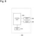
- Fig. 8 is a block diagram of the charger 200.
- the charger 200 may include a connection part 211 that is electrically connectable to the power supply unit 110.
- the connection part 211 may include a pair of electrical terminals 211t.
- the pair of electrical terminals 111t of the power supply unit 110 for electrically connecting the load 121R can also serve as the pair of electrical terminals 111t of the power supply unit 110 for electrically connecting the charger 200. That is, the pair of electrical terminals 211t of the charger 200 may be configured to be connectable to the pair of electrical terminals 111t of the power supply unit 110.
- connection part 111 of the power supply unit 110 is configured to be exclusively connectable to one of the load 121R that vaporizes or atomizes the inhalation component source with electric power from the power supply 10 and the external unit such as the charger 200.
- the connection part 111 of the power supply unit 110 is connectable to each of the load 121R and the external unit such as the charger 200, but, when being connected to one of the load 121R and the external unit such as the charger 200, the connection part 111 of the power supply unit 110 is configured to be unable to be connected to the other of the load 121R and the external unit such as the charger 200.
- the charger 200 may include an external power supply 210 for charging the power supply 10 in the power supply unit 110.
- the charger 200 is configured to be electrically connectable and disconnectable to/from the external power supply 210, and may be a device that electrically connects the power supply 10 of the power supply unit 110 to the external power supply 210.
- the external power supply 210 that is electrically connectable and disconnectable to/from the charger 200 may be a storage battery that outputs a direct current.
- the external power supply 210 that is electrically connectable and disconnectable to/from the charger 200 may be an AC commercial power system that is output from a receptacle outlet at home. Note that the charger 200 may have any shape.
- the charger 200 may be shaped similar to a universal serial bus (USB) memory having a USB terminal connectable to a USB port.
- the charger 200 may be cradle-shaped for holding the power supply unit 110 or case-shaped for accommodating the power supply unit 110 therein.
- the external power supply 210 is incorporated in the charger 200, and has size and weight that can be carried by a user.
- the charger 200 may include a control part 250 that controls charging of the power supply 10. Furthermore, the charger 200 may include a current sensor 230 and a voltage sensor 240, where appropriate.
- the current sensor 230 acquires a charging current to be supplied from the charger 200 to the power supply 10.
- the voltage sensor 240 acquires a voltage difference between the pair of electrical terminals 211t of the charger 200.
- the control part 250 of the charger 200 uses an output value from the current sensor 230 and/or the voltage sensor 240 to control the charging of the power supply 10 of the power supply unit 110.
- the charger 200 may include an inverter that converts an alternating current into a direct current.
- the charger 200 may further include a voltage sensor that acquires a direct-current voltage output from the inverter, and a converter capable of boosting and/or stepping down the direct-current voltage output by the inverter.
- the configuration of the charger 200 is not limited to the above-described configuration, and may be comprised of a divider circuit, LDO, or the like or may include these divider circuit, LDO and the like.
- the charger 200 includes a sensor that can output an output value related to an electrical resistance value of the first resistor 150 provided in the power supply unit 110.
- the output value related to the electrical resistance value may be an electrical resistance value itself, or may be a physical quantity that can be converted into the electrical resistance value.
- the output value related to the electrical resistance value may be a voltage drop amount (potential difference) in the first resistor 150, or may be a current value of a current flowing through the first resistor 150.
- Examples of the sensor that can output the output value related to the electrical resistance value of the first resistor 150 include the above-described current sensor 230 or voltage sensor 240.
- the voltage sensor 240 can output a value of a voltage applied to the first resistor 150 of the power supply unit 110.
- the current sensor 230 can output a value of a current flowing through the first resistor 150 of the power supply unit 110.
- Each of the value of the voltage applied to the first resistor 150 and the value of the current flowing through the first resistor 150 is an output value related to the electrical resistance value of the first resistor 150.
- the charger 200 can distinguish the type of the power supply unit 110 or the power supply 10 in the power supply unit, using the value related to the electrical resistance value of the first resistor 150 in the power supply unit. That is, the charger 200 can distinguish the type of the power supply unit 110 or the power supply 10 without communicating with the power supply unit 110, by changing the electrical resistance value of the first resistor 150 according to a different type of power supply unit 110 or power supply 10.
- the first resistor 150 of the power supply unit 110 can function as a known resistor used for authentication.
- the control part 250 of the charger 200 may be configured to be capable of detecting whether the power supply unit 110 is connected to the connection part 211.
- the connection of the power supply unit 110 to the connection part 211 can be detected by a known method.
- the control part 250 can detect the connection of the power supply unit 110 by detecting the voltage difference between the pair of connection terminals 211t.
- the control part 250 of the charger 200 may be configured to be incapable of communicating with the control part 50 of the power supply unit 110.
- a communication terminal for communicating between the control part 250 of the charger 200 and the control part 50 of the power supply unit 110 is unnecessary.
- the power supply unit 110 has only two electrical terminals, one for a main positive bus and the other for a main negative bus. Simplifying the structure of the inhalation component generation device 100 can improve the weight, cost and production efficiency of the inhalation component generation device 100.
- the inhalation component generation device 100 is configured not to perform communication between the control part 250 of the charger 200 and the control part 50 of the power supply unit 110, the standby power of the transmitter and receiver of each of the control parts 250 and 50 can be reduced, thereby improving the utilization efficiency of the electric power that is stored in the power supply 10 of the power supply unit 110 and the external power supply 210 of the charger 200. Furthermore, since the communication between the control part 250 of the charger 200 and the control part 50 of the power supply unit 110 does not cause the malfunction, the quality of the inhalation component generation device 100 is improved.
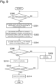
- Fig. 9 is a flowchart illustrating an example of a control method by the control part 250 of the charger 200.
- the control part 250 firstly, detects the connection of the power supply unit 110 to the charger 200 (step S300). The control part 250 waits until the power supply unit 110 is connected to the connection part 211 of the charger 200.
- the control part 250 acquires a value related to the electrical resistance value of the first resistor 150 in the power supply unit 110 (step S301).
- the value related to the electrical resistance value of the first resistor 150 may be an electrical resistance value itself of the first resistor 150, may be a voltage drop amount (potential difference) in the first resistor 150, or may be a current value of a current flowing through the first resistor 150.
- the second switch 174 of the power supply unit 110 is open. More specifically, when the control part 250 acquires the value related to the electrical resistance value of the first resistor 150, it is preferable that the power supply unit 110 is in a first mode in which the connection part 111 and the power supply 10 are electrically disconnected from each other. In this state, when a minute current is supplied from the charger 200 to the power supply unit 110, the authentication circuit 190 including the first resistor 150 for authentication functions, whereby the control part 250 can acquire the value related to the electrical resistance value of the first resistor 150.
- control part 250 may acquire the values related to the electrical resistance value of the first resistor 150 a plurality of times and derive, from a moving average, a simple average, a weighted average and the like of these acquired values, the value related to the electrical resistance value of the first resistor 150 that is used in step S303 (described later).
- the plurality of values related to the electrical resistance value of the first resistor 150 may be acquired from one or more pulses of the minute current.
- the control part 250 may supply the minute current to the power supply unit 110 not in a moment but for a predetermined duration time. It is preferable that the control part 250 acquires the value related to the electrical resistance value of the first resistor 150 without the use of the values output by the current sensor 230 and the voltage sensor 240 immediately after the minute current is supplied to the power supply unit 110 or at the timing when supply of the minute current to the power supply unit 110 is stopped.
- control part 250 acquires the value related to the electrical resistance value of the first resistor 150 using the values output by the current sensor 230 and the voltage sensor 240 at an intermediate time point of the predetermined duration time or at an time point in the vicinity of the intermediate time point.
- a time lag may be provided from the time point when the current sensor 230 and the voltage sensor 240 detect the value related to the electrical resistance value of the first resistor 150 until the time point when the control part 250 acquires the value related to the electrical resistance value of the first resistor 150 that is output from the current sensor 230 and the voltage sensor 240, by combining a delay circuit with the current sensor 230 and the voltage sensor 240 for acquiring the value related to the electrical resistance value of the first resistor 150.
- the current sensor 230 and the voltage sensor 240 it is sufficient for the current sensor 230 and the voltage sensor 240 to detect the value related to the electrical resistance value of the first resistor 150 before the predetermined time period elapses since detection of the connection of the power supply unit 110 in the first mode in step S301. That is, it should be noted that it is not necessary that the control part 250 acquires the value related to the electrical resistance value of the first resistor 150 before the predetermined time period elapses since detection of the connection of the power supply unit 110.
- control part 250 determines whether to change a predetermined control or whether to perform the predetermined control with respect to the power supply unit 110, based on the output value of the sensor, i.e., the value related to the electrical resistance value acquired in step S301 (step S303).
- the predetermined control may be a control for charging the power supply 10 of the power supply unit 100.
- the first resistor 150 may be used as a known resistor used for authentication. That is, if the electrical resistance value of the first resistor 150 is changed according to the type of the power supply unit 110, the control part 250 can perform an optimal control according to the type of the power supply unit 110.
- the control part 250 when the above-described output value is outside a predetermined range or does not satisfy a predetermined condition, the control part 250 does not charge the power supply 10.
- the control part 250 when the output value is within the predetermined range or satisfies the predetermined condition, the control part 250 may be configured to charge the power supply 10. That is, the change of the predetermined control with respect to the power supply unit 110 in step S301 includes changing such that the charging process is not performed in steps S304 to S314 (described later).
- the control part 250 may be configured to output an abnormal signal in the case where the above-described output value is outside the predetermined range or does not satisfy the predetermined condition.
- the change of the predetermined control with respect to the power supply unit 110 in step S301 may be at least one of changes of a current value, a rate and a charging time period for charging the power supply.
- the change of the predetermined control may be a change of the rate of the charging current. That is, the control part 250 can change the rate of the charging current according to the type of the power supply unit 110 or the power supply 10.
- the control part 50 can perform the charge control with a charging current at a high rate of, for example, 2 C or higher, and when the power supply 10 disabling rapid charging is used, the control part 50 can perform the charge control with a charging current at a low rate of, for example, 1 C or lower.
- the rate of the charging current is mainly changed in CC charging (described later).
- the control part 250 of the charger 200 may include a memory that has stored the values related to the electrical resistance value of the first resistor 150 and the database associating the power supply unit 110 or the power supply 10 with charging conditions such as the rate of the charging current.
- control part 250 of the charger 200 is configured to determine whether to change a predetermined control or whether to perform the predetermined control, based on the output value that is output before a predetermined time period (described later) elapses since detection of the connection of the power supply unit 110, i.e., the value related to the electrical resistance value of the first resistor 150.
- the predetermined time period corresponds to a time period from when the control part 50 of the power supply unit 110 detects the connection of the charger 200 until the second switch 174 is closed.
- control part 250 performs a predetermined control, i.e., the charge control in the present embodiment.
- a predetermined control i.e., the charge control in the present embodiment.
- the control part 250 of the charger 200 firstly estimates a voltage of the power supply 10 using the voltage sensor 240 (step S304).
- the second switch 174 may be closed while the predetermined control is performed, i.e., in the step after step S304. If the electrical resistance value of the first resistor 150 is sufficiently higher as compared with an internal resistance (impedance) of the power supply 10, the charging current from the charger 200 flows mainly through the charging circuit 192 including the power supply 10, and scarcely flows in the authentication circuit 190. As such, it is preferable that the second switch 174 is configured to selectively cause one of the charging circuit 192 and the authentication circuit 190 to function. This can prevent loss of electric power in the power supply unit 110 during charging of the power supply 10 as compared with the case where the majority of the charging current from the charger 200 flows through the first resistor 150.
- the control part 250 determines whether the voltage of the power supply 10 is equal to or higher than a switching voltage (step S306).
- the switching voltage is a threshold for dividing into a section of constant current charging (CC charging) and a section of constant voltage charging (CV charging).
- the switching voltage may be, for example, in the range of 4.0 V to 4.1 V.
- the control part 250 charges the power supply 10 by a constant current charging method (step S308).
- the control part 250 charges the power supply 10 by a constant voltage charging method (step S310).
- the constant voltage charging method the voltage of the power supply 10 increases as charging proceeds, and the difference between the voltage of the power supply 10 and the charging voltage is reduced, whereby the charging current decreases.
- the control part 250 determines whether the charging current is equal to or smaller than a predetermined charging completion current (step S312).
- the charging current can be acquired by the current sensor 230 in the charger 200.
- the charging current is larger than the predetermined charging completion current, charging of the power supply 10 is continued by the constant voltage charging method.
- the control part 250 determines that the power supply 10 is fully charged, and stops the charging (step S314).
- the condition for stopping the charging include the time period that has elapsed since the start of charging by the constant current charging method or charging by the constant voltage charging method, the voltage of the power supply 10, and the temperature of the power supply 10, in addition to the charging current.
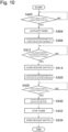
- Fig. 10 is a flowchart illustrating an example of a control method by the control part 50 of the power supply unit 110 in a charging mode.
- the charging mode is a mode in which the power supply 10 can be charged.
- the control part 50 detects the connection of the charger 200 to the power supply unit 110 (step S400).
- the detection of the connection of the charger 200 for example, as described above, can be determined based on a voltage drop amount (Wake signal) in the second resistor 152.
- the second switch 174 is configured to be maintained in an open state when the charger 200 is not connected to the connection part 111 of the power supply unit 110. In the state in which the second switch 174 is open, the power supply unit 110 is in a standby mode (first mode) in which the connection part 111 and the power supply 10 are electrically disconnected from each other.
- step S404 When detecting the connection of the power charger 200 to the power supply unit 110, the control part 50 activates a timer (step S404). This timer measures the time period that has elapsed since detection of the connection of the charger 200.
- the control part 50 causes the notification part 40 to function in a first manner where appropriate (step S406).
- the notification part 40 is a light emitting element such as an LED
- the control part 50 causes the notification part to emit light in a predetermined first light emission manner.
- the control part 50 may be configured to cause the notification part 40 to function in at least partial time period of the above-described predetermined time period.
- the notification part 40 may be provided in the charger 200, and furthermore the control part 250 of the charger may control the notification part 40 provided in the charger 200.
- the control part 250 of the charger controls the notification part 40
- the control part 250 of the charger causes the notification part 40 to function in the first manner when the control part 250 of the charger detects the connection of the power supply unit 110.
- the control part 50 determines whether the predetermined time period has elapsed since detection of the connection of the charger 200 (step S412).
- the second switch 174 is maintained in the open state until the predetermined time period elapses since detection of the connection of the charger 200. That is, the standby mode (first mode) in which the connection part 111 and the power supply 10 are electrically disconnected from each other is maintained.
- the control part 50 closes the second switch 174 (step S414).
- the second switch 174 the power supply unit 110 transitions to an operation mode (second mode) in which the connection part 111 and the power supply 10 are electrically connected to each other.
- the control part 250 of the charger 200 starts the charging as described above (step S308 and step S310) in the operation mode in which the second switch 174 is closed, charging of the power supply 10 is started.
- the detection of the charger 200 by the control part 50 is the condition for transitioning from the first mode in which the authentication circuit 190 functions to the second mode in which the charging circuit 192 functions.
- it transitions from the first mode to the second mode by controlling the second switch 174.
- the control part 50 of the power supply unit 110 maintains the standby mode (first mode) until a predetermined time period elapses since detection of the connection of the charger 200. It is preferable that this predetermined time period is equal to or longer than a time period required from when the control part 250 of the charger 200 detects the connection of the power supply unit 110 until the control part 250 of the charger 200 acquires the value related to the electrical resistance value of the first resistor 150 in the power supply unit 110. This enables the control part 250 of the charger 200 to acquire the value related to the electrical resistance value of the first resistor 150 while the power supply unit 110 is in the standby mode (first mode).
- the control part 50 When the control part 50 is in the operation mode (second mode) in which the second switch 174 is closed, it is preferable that the control part 50 causes the notification part 40 to function in a second manner (step S420).
- the notification part 40 is a light emitting element such as an LED
- the control part 50 causes the notification part 40 to emit light in a predetermined second light emission manner.
- the notification part 40 may be provided in the charger 200, and furthermore the control part 250 of the charger may control the notification part 40 provided in the charger 200.
- control part 250 of the charger controls the notification part 40
- the control part 250 of the charger causes the notification part 40 to function in the second manner after the above-described predetermined time period has elapsed since the control part 250 of the charger detected the connection of the power supply unit 110.
- control part 50 and/or the control part 250 cause the notification part 40 to function in different manners after the elapse of the above-described predetermined time period and within the predetermined time period. That is, it is preferable that the first manner of the notification part 40, e.g., the first light emission manner is different from the second manner of the notification part 40, e.g., the second light emission manner. This enables the notification part 40 to notify a user of whether the predetermined time period has elapsed.
- control part 50 and/or the control part 250 may be configured to cause the notification part 40 to function only one of after the elapse of the predetermined time period and for the predetermined time period. That is, the control part 50 and/or the control part 250 may cause the notification part 40 to function at at least one timing of steps S406 and S420. This enables the notification part 40 to notify a user of whether the predetermined time period has elapsed.
- the control part 50 determines whether to detect the completion of the charging (step S426).
- the completion of the charging is detected by detecting, for example, that the connection of the charger 200 is released.
- the completion of the charging may be detected by detecting, for example, that the charging current from the charger 200 is stopped.
- the control part 50 stops the function of the notification part 40 and the timer, and opens the second switch 174 (step S430, step S432, and step S434).
- the control part 50 of the power supply unit 110 performs the above-described control flow in a predetermined control cycle.
- the control part 250 of the charger 200 may perform the above-described control flow in a control cycle different from the control cycle of the control part 50.
- the control part 250 of the charger 200 can complete the above-described steps S301 and S303 rapidly in the period from when the control part 50 activates the timer until the predetermined time period elapses (step S412).
- the control part 50 is configured to control the second switch 174 to thereby transition from the first mode to the second mode when the condition for transitioning from the second mode in which the charging circuit 192 functions to the first mode in which the authentication circuit 190 functions is fulfilled. For example, in the above-described flowchart, when detecting the completion of the charging, the control part 50 controls the second switch 174 to thereby transition from the first mode to the second mode.
- control part 50 controls the second switch so that the time period (corresponding to the above-described predetermined time period) from when the condition for transitioning from the first mode to the second mode is fulfilled until the first mode is transitioned to the second mode is longer than the time period from when the condition for transitioning from the second mode to the first mode is fulfilled until the second mode is transitioned to the first mode.
- the aforementioned flow illustrated in Fig. 9 can be performed by the control part 250 of the charger 200. That is, the control part 250 may have a program that causes the charger 200 for the inhalation component generation device to execute the aforementioned flow illustrated in Fig. 9 . Furthermore, it should be noted that a storage medium in which the program is stored is also included in the scope of the present invention.
- the aforementioned flow illustrated in Fig. 10 can be performed by the control part 50 of the power supply unit 110. That is, the control part 50 may have a program that causes the power supply unit 110 for the inhalation component generation device to execute the aforementioned flow illustrated in Fig. 10 . Furthermore, it should be noted that a storage medium in which the program is stored is also included in the scope of the present invention.
- the first switch 172 includes a parasitic diode (also referred to as a body diode) so that the flowing direction of the current output from the power supply 10 that flows into the first switch 172 through the first node 154 is a reverse direction when the external unit such as the charger 200 is not connected to the connection part 111.
- the first switch 172 includes a parasitic diode so that the direction from the high potential side to the low potential side of the power supply 10 is the reverse direction.
- the second switch 174 includes a parasitic diode so that the flowing direction of the charging current that is input from the connection part 111 and charges the power supply 10 is the reverse direction.
- the second switch 174 includes a parasitic diode so that the direction from the high potential side to the low potential side of the power supply 10 is a forward direction. Accordingly, in the case where nothing is connected to the connection part 110 of the power supply unit 110 and the first switch 172 and the second switch 174 are open, the electrical circuit in the power supply unit 110 is appropriately equivalent to a circuit illustrated in Fig. 12 . In the equivalent circuit illustrated in Fig.
- reference numeral 172a denotes a parasitic diode so that the flowing direction of the current output from the power supply 10 that flows into the first switch 172 through the first node 154 is a reverse direction.
- reference numeral 172a denotes a parasitic diode so that the direction from the high potential side to the low potential side of the power supply 10 is the reverse direction.
- Vsatt represents an output voltage of the power supply 10 that can vary from a fully charged voltage to the discharge terminal voltage
- R 1 represents an electrical resistance value of the first resistor 150
- R 2 represents an electrical resistance value of the second resistor 152.
- Fig. 11 shows a relationship between a voltage applied to the parasitic diode 172a and a current flowing through the parasitic diode 172a.
- a current flowing through the parasitic diode 172a in the forward direction and a voltage applied to cause the current flowing in the forward direction are represented using a plus (+) sign
- a current flowing through the parasitic diode 172a in the reverse direction and a voltage applied to cause the current flowing in the reverse direction are represented using a minus (-) sign.
- the absolute values are used to compare two voltage values.
- the leak current flows through the parasitic diode 172a of the first switch 172, the leak current flows into the control part 50. Therefore, in some cases, the control part 50 cannot operate normally. Consequently, it is preferable to minimize a value of the current unintentionally leaking from the parasitic diode 172a, that is, the first switch 172 in the open state.
- the leak current has correlation with the voltage applied to the parasitic diode 172a in the reverse direction. Even in the case where the voltage lower than the breakdown voltage V Break is applied, the electrical potential of an electron causing the leak current is increased when the voltage applied in the reverse direction is increased. Consequently, it is preferable to minimize a value V diode of the voltage applied to the parasitic diode 172a, i.e., the first switch 172.
- the electrical resistance value R 2 of the second resistor 152 is lower than the electrical resistance value R 1 of the first resistor 150.
- the value of V diode of the voltage applied to the parasitic diode 172a, i.e., the first switch 172 is reduced, whereby the leak current can be reduced.
- the ratio of the electrical resistance value R 1 of the first resistor 150 to the electrical resistance value R 2 of the second resistor 152 is designed to apply the voltage lower than the breakdown voltage to the parasitic diode 172a when the external unit is not connected to the connection part 111. This can prevent the function of the parasitic diode 172a from being destroyed.
- this dark current is designed to be smaller than a value of current allowing discharging of the power supply 10 when the load 121R of the atomizing unit 120 is connected to the connection part 111.
- the electrical resistance values R 1 and R 2 of the first resistor 150 and the second resistor 152 are designed so that a value of the current flowing through the first resistor 150 and the second resistor 152 when the external unit is not connected to the connection part 111 is smaller than a value of the current allowing discharging of the power supply 10 when the load 121R is connected to the connection part 111. This can prevent the power consumption of the power supply unit 110 in the standby state.
- the current allowing discharging of the power supply 10 when the load 121R is connected to the connection part 111 may be adjusted by the above-described PWM control or PFM control.
- This dark current is related to the accuracy of the connection detection of the external unit by the detecting part of the control part 50. That is, as described above, the detecting part of the control part 50 detects the connection of the external unit by distinguishing between the voltage drop amount of the second resistor 152 when the external unit is connected to the connection part 111 and the voltage drop amount of the second resistor 152 when the external unit is not connected to the connection part 111.
- the electrical resistance values of the first resistor 150 and the second resistor 152 are enormously increased, the dark current becomes enormously minute current value.
- the voltage drop amount of the second resistor 152 depends on the electrical resistance values of the first resistor 150 and the second resistor 152.
- the first resistor 150 has the electrical resistance value such that the detecting part of the control part 50 can distinguish between the voltage drop amount of the second resistor 152 when the external unit is connected to the connection part 111 and the voltage drop amount of the second resistor 152 when the external unit is not connected to the connection part 111.
- V Wake V Batt ⁇ R 2 /(R 1 + Rz).
- This relational expression can be regarded to specify an upper limit value of the first resistor 150.
- the electrical resistance values of the first resistor 150 and the second resistor 152 may be designed so that a value of the current (dark current) flowing through the first resistor 150 and the second resistor 152 when the external unit is not connected to the connection part 111 is preferably 0.200 mA or less. This can suppress the dark current more efficiently. Note that this can also suppress the connection detection errors efficiently.
- the electrical resistance values of the first resistor 150 and the second resistor 152 may be designed so that a rate of the current (dark current) flowing through the first resistor 150 and the second resistor 152 when the external unit is not connected to the connection part 111 is preferably 0.07 mC or less. This can reduce the power consumption associated with the dark current efficiently while enabling the connection detection using the dark current flowing through the second resistor 152. Note that this can also suppress the connection detection errors efficiently.
- the control part 250 of the external unit such as the charger 200 may include the voltage sensor 240 that can acquire the electrical resistance value of the first resistor 150 in the power supply unit 110.
- the voltage sensor 240 outputs the electrical resistance value of the first resistor 150 accurately. Accordingly, it is preferable that the voltage drop amount in the first resistor 150 is greater than the resolution of the voltage sensor 240 when the voltage sensor 240 acquires the electrical resistance value of the first resistor 150.
- the electrical resistance value R 1 of the first resistor 150 is designed so that the voltage drop amount in the first resistor when the external unit discharges to the power supply unit at a predetermined current value is greater than the resolution of the sensor of the external unit that outputs the voltage drop amount in the first resistor 150.
- the charging current from the charger 200 mainly flows into the power supply 10 from the second node 156 (see Fig. 7 ).
- a part of the current flows through the first resistor 150 without flowing into the power supply 10. Since the current flowing through the first resistor 150 becomes a loss, it is preferable that the current flowing through the first resistor 150 is reduced as small as possible. From such viewpoints, it is preferable that the electrical resistance value R 1 of the first resistor 150 is higher than the internal resistance value R impedance of the power supply 10.
- the load 121R that vaporizes or atomizes the inhalation component source with electric power from the power supply 10 is connected to the connection part 111 of the power supply unit 110, the current discharged from the power supply 10 mainly flows through the second node 156, the load 121R, the first node 154, and the first switch 172 in this order, and then is returned to the power supply 10 (see Fig. 5 ).
- the electrical resistance value R 1 of the first resistor 150 is higher than the electrical resistance value R load of the load 121R.
- the second resistor 152 and the capacitor 164 are connected to each other in series. That is, the electrical path including the second resistor 152 and the capacitor 164 form a so-called RC circuit.
- the voltage output from this RC circuit follows a circuit equation "V 0 ⁇ exp(-t/ ⁇ ) + Vi" in the RC circuit.
- the voltage output from the RC circuit corresponds to a change in potential at the first node 154, i.e., a change in voltage drop amount in the second resistor 152.
- Vo corresponds to the voltage drop amount (potential difference) in the second resistor 152 when nothing is connected to the power supply unit 110.
- Vi represent a final value of the potential difference.
- R represents an electrical resistance value of a resistor in the RC circuit
- C represents the capacitance of a capacitor in the RC circuit.
- R is an electrical resistance value of the second resistor 152
- C is the capacitance of the capacitor 164.
- the control part 50 When the control part 50 detects the connection of the external unit to the connection part 111, the control part 50 needs to detect the voltage drop amount in the second resistor 152 after the voltage drop amount in the second resistor 152 sufficiently approaches the final value. From such viewpoints, it is preferable that the time constant ⁇ is small. That is, it is preferable that the electrical resistance value of the second resistor 152 is low.
- the electrical resistance value of the second resistor 152 is designed such that the time constant ⁇ of the RC circuit formed by the second resistor 152 and the capacitor 164 is shorter than a cycle in which the detecting part of the control part 50 detects the voltage drop amount in the second resistor 152.
- the voltage drop amount in the second resistor 152 varies to a value sufficiently close to the final value in a time period shorter than the detection cycle of the detecting part of the control part 50. Accordingly, the control part 50 can detect the connection of the external unit to the connection part 111 of the power supply unit 110 rapidly and more accurately.
- the voltage drop amount in the second resistor 152 is detected by the detecting part of the control part 50 in a single sequence consecutively a plurality of times, and the control part 50 may use an average value of these detected voltage drop amounts as the voltage drop amount in the second resistor 152.
- the electrical resistance value of the second resistor 152 is designed such that the time constant ⁇ of the RC circuit formed by the second resistor 152 and the capacitor 164 is shorter than a cycle in which this sequence is performed.
- control part 50 of the power supply unit 110 cannot communicate with the control part 250 of the external unit such as the charger 200, it is difficult to synchronize the control parts 50 and 250.
- the control part 50 rapidly detects the connection of the external unit not to cause the deviation between the control by the control part 50 of the power supply unit 110 and the control by the control part 250 of the external unit such as the charger 200.
- the present invention can be also applied to an inhalation component generation system including an external unit for an inhalation component generation device, and a plurality of power supply units that are electrically connectable to a connection part of the external unit.
- the external unit is the charger 200.
- the configurations of the charger 200 and each of the power supply units 110 are as described above. Accordingly, the detailed description of configurations of the charger 200 and each of the power supply units 110 is omitted. However, the electrical resistance values of the first resistors 150 in the power supply units 110 may be different from one another.
- the electrical resistance value of the first resistor 150 in each of the plurality of the power supply units 110 becomes higher as the power supply unit 110 has the power supply 10 that is chargeable at a higher rate. That is, the electrical resistance value of the first resistor 150 provided in each of the plurality of power supply units 110 is selected to a higher value as the power supply unit 110 has the power supply 10 that is chargeable at a higher rate.
- the electrical resistance value of the first resistor 150 in the power supply unit 110 is selected to a higher value as the power supply unit 110 has the power supply 10 that is chargeable at a higher rate. Therefore, the amount of unnecessary current that does not contribute to the charging of the power supply 10 can be suppressed even in the power supply unit 110 having the power supply 10 that is chargeable at a higher rate.
Landscapes
- Engineering & Computer Science (AREA)
- Power Engineering (AREA)
- Human Computer Interaction (AREA)
- Charge And Discharge Circuits For Batteries Or The Like (AREA)
Claims (12)
- Inhalationskomponentenerzeugungssystem, umfassend eine Ladeeinrichtung (200) für eine Inhalationskomponentenerzeugungsvorrichtung (100) und eine Stromversorgungseinheit (110) der Inhalationskomponentenerzeugungsvorrichtung (100), wobei die Ladeeinrichtung (200) Folgendes umfasst:einen Verbindungsteil (211), der zwei Klemmen (211t) umfasst, die mit der Stromversorgungseinheit (110) elektrisch verbindbar sind;einen Sensor (230; 240), der fähig ist, einen Wert einer Spannungsdifferenz zwischen den zwei Klemmen (211t) oder eines Stroms, der in und aus den zwei Klemmen (211t) strömt, zu erfassen, wobei der Wert auf einen elektrischen Widerstandswert eines Widerstands (150) bezogen ist, der in der Stromversorgungseinheit (110) bereitgestellt ist, und den Wert als einen Ausgabewert auszugeben; undeinen ersten Steuerteil (250), der so konfiguriert ist, dass er basierend auf dem Ausgabewert eine vorbestimmte Steuerung in Bezug auf die Stromversorgungseinheit (110), die mit dem Verbindungsteil (211) verbindbar ist, ändert, wobei die vorbestimmte Steuerung eine Steuerung zum Laden einer Stromversorgung (10) ist, die in der Stromversorgungseinheit (110) bereitgestellt ist, und wobei Ändern der vorbestimmten Steuerung Folgendes umfasst:
Ändern einer C-Rate zum Laden der Stromversorgung (10) durch die zwei Klemmen (211t) in eine C-Rate, die gemäß einem Typ der Stromversorgungseinheit (110) bestimmt wird, wobei der Typ gemäß dem Ausgabewert bestimmt wird,wobei die Stromversorgungseinheit (110) so konfiguriert ist, dass die zwei Klemmen (211t) der Ladeeinrichtung (200) nicht fähig sind, mit der Stromversorgungseinheit (110) verbunden zu sein, während eine Last (121R) einer abnehmbar in der Inhalationskomponentenerzeugungsvorrichtung (100) enthaltenen Zerstäubungseinheit (120) mit der Stromversorgungseinheit (110) verbunden ist. - Inhalationskomponentenerzeugungssystem nach Anspruch 1, wobeider erste Steuerteil (250) so konfiguriert ist, dass er die Stromversorgung (10) nicht lädt oder so konfiguriert ist, dass er ein anormales Signal ausgibt, wenn der Ausgabewert außerhalb eines vorbestimmten Bereichs liegt oder eine vorbestimmte Bedingung nicht erfüllt, undder erste Steuerteil (250) so konfiguriert ist, dass er die Stromversorgung (10) lädt oder so konfiguriert ist, dass er das anormale Signal nicht ausgibt, wenn der Ausgabewert innerhalb des vorbestimmten Bereichs liegt oder die vorbestimmte Bedingung erfüllt.
- Inhalationskomponentenerzeugungssystem nach Anspruch 1 oder 2, wobeider erste Steuerteil (250) so konfiguriert ist, dass er fähig ist zum Erkennen von Verbindung der Stromversorgungseinheit (110) mit dem Verbindungsteil (211), undder erste Steuerteil (250) so konfiguriert ist, dass er bestimmt, ob die vorbestimmte Steuerung geändert werden soll oder ob die vorbestimmte Steuerung durchgeführt werden soll, basierend auf dem Ausgabewert, der nach Erkennen von Verbindung der Stromversorgungseinheit (110) ausgegeben wurde.
- Inhalationskomponentenerzeugungssystem nach einem vorstehenden Anspruch, wobei
ein elektrischer Widerstandswert des Widerstands (150) unabhängig von einem Zustand der Stromversorgung (10) konstant ist. - Inhalationskomponentenerzeugungssystem nach einem vorstehenden Anspruch, wobei
der Widerstand (150) einen bekannten elektrischen Widerstandswert aufweist. - Inhalationskomponentenerzeugungssystem nach einem vorstehenden Anspruch, wobei
die Stromversorgungseinheit (110) Folgendes einschließt:einen ersten elektrischen Pfad (190), der durch den Widerstand (150) mit der Ladeeinrichtung (200) elektrisch verbindbar ist;einen zweiten elektrischen Pfad (192), der mit der Ladeeinrichtung (200) elektrisch verbindbar ist, während der Widerstand (150) umgangen wird; undein Schalter (172; 174), der so konfiguriert ist, dass er fähig ist, den zweiten elektrischen Pfad zu öffnen und zu schließen, undder Schalter (172; 174) so konfiguriert ist, dass er geschlossen ist, während die vorbestimmte Steuerung durchgeführt wird. - Inhalationskomponentenerzeugungssystem nach einem vorstehenden Anspruch, wobeidie Stromversorgungseinheit (110) einen zweiten Steuerteil (50) einschließt,der zweite Steuerteil (50) so konfiguriert ist, dass er fähig ist, zwischen einem ersten Betriebsmodus, in dem der Verbindungsteil (211) von der Stromversorgung (10) oder dem zweiten Steuerteil (50) elektrisch getrennt ist, und einem zweiten Betriebsmodus, in dem der Verbindungsteil (211) mit der Stromversorgung (10) oder dem zweiten Steuerteil (50) elektrisch verbunden ist, zu steuern, undder erste Steuerteil so konfiguriert ist, dass er bestimmt, ob die vorbestimmte Steuerung geändert werden soll oder ob die vorbestimmte Steuerung durchgeführt werden soll, basierend auf dem Ausgabewert, der während des ersten Betriebsmodus erfasst wurde.
- Inhalationskomponentenerzeugungssystem nach Anspruch 7, wobei
der zweite Steuerteil (50) so konfiguriert ist, dass er die Stromversorgungseinheit (110) nach einem Verstreichen einer vorbestimmten Zeitspanne seit Erkennen von Verbindung der Ladeeinrichtung (200) vom ersten Betriebsmodus in den zweiten Betriebsmodus übergibt. - Inhalationskomponentenerzeugungssystem nach Anspruch 8, wobei
der erste Steuerteil (250) so konfiguriert ist, dass er bestimmt, ob die vorbestimmte Steuerung geändert werden soll oder ob die vorbestimmte Steuerung durchgeführt werden soll, basierend auf dem Ausgabewert, der ausgegeben wird, bevor die vorbestimmte Zeitspanne seit Erkennen von Verbindung der Stromversorgungseinheit (110) verstreicht oder einem elektrischen Widerstandswert des Widerstands (150;) der von dem Sensor (230; 240) erfasst wird, bevor die vorbestimmte Zeitspanne seit Erkennen von Verbindung der Stromversorgungseinheit (110) verstrichen ist. - Inhalationskomponentenerzeugungssystem nach Anspruch 8 oder 9, wobei
die vorbestimmte Zeitspanne gleich lang oder länger ist als eine Zeitspanne, die erforderlich ist, seit der erste Steuerteil die Verbindung der Stromversorgungseinheit (110) erkennt bis der erste Steuerteil (250) den elektrischen Widerstandswert des Widerstands (150) erfasst. - Inhalationskomponentenerzeugungssystem nach einem der Ansprüche 8 bis 10, weiter umfassend:einen Benachrichtigungsteil (40),wobei der erste Steuerteil (250) oder der zweite Steuerteil (50) so konfiguriert sind, dass sie bewirken, dass der Benachrichtigungsteil (40) in einer mindestens teilweisen Zeitspanne der vorbestimmten Zeitspanne arbeitet.
- Inhalationskomponentenerzeugungssystem nach einem der Ansprüche 1 bis 3, weiter umfassend:eine Vielzahl der Stromversorgungseinheiten (110), die die Stromversorgungseinheit (110) einschließt,wobei der Sensor (230; 240) fähig ist, einen Ausgabewert auszugeben, der auf einen elektrischen Widerstandswert des Widerstands (150) bezogen ist, der in jeder der Stromversorgungseinheiten (110) bereitgestellt ist,wobei der Widerstand (150) parallel zu einer Stromversorgung (10) der Stromversorgungseinheit (110) in Bezug auf den Verbindungsteil (211) verbunden ist,wobei die Stromversorgungseinheit (110) einen Schalter (172; 174) einschließt, der fähig ist zum elektrischen Verbinden und Trennen der Stromversorgung (10) mit/von der Ladeeinrichtung (200) und so konfiguriert ist, dass er geschlossen ist, während die vorbestimmte Steuerung durchgeführt wird, undder elektrische Widerstandswert des Widerstands (150) in jeder der Vielzahl der Stromversorgungseinheiten (110) höher wird, wenn die Stromversorgungseinheit (110) mit einer höheren C-Rate geladen werden kann.
Applications Claiming Priority (1)
| Application Number | Priority Date | Filing Date | Title |
|---|---|---|---|
| PCT/JP2018/003551 WO2019150545A1 (ja) | 2018-02-02 | 2018-02-02 | 吸引成分生成装置用の外部ユニット、吸引成分生成システム、吸引成分生成装置用の外部ユニットを制御する方法、及びプログラム |
Publications (4)
| Publication Number | Publication Date |
|---|---|
| EP3738455A1 EP3738455A1 (de) | 2020-11-18 |
| EP3738455A4 EP3738455A4 (de) | 2021-02-17 |
| EP3738455C0 EP3738455C0 (de) | 2024-10-09 |
| EP3738455B1 true EP3738455B1 (de) | 2024-10-09 |
Family
ID=67478150
Family Applications (1)
| Application Number | Title | Priority Date | Filing Date |
|---|---|---|---|
| EP18903879.7A Active EP3738455B1 (de) | 2018-02-02 | 2018-02-02 | Externe einheit für eine inhalationskomponentenerzeugungsvorrichtung, inhalationskomponentenerzeugungssystem, verfahren zur steuerung einer externen einheit für eine inhalationskomponentenerzeugungsvorrichtung und programm |
Country Status (9)
| Country | Link |
|---|---|
| US (1) | US12108801B2 (de) |
| EP (1) | EP3738455B1 (de) |
| JP (1) | JP6833075B2 (de) |
| KR (1) | KR102511168B1 (de) |
| CN (1) | CN111655060B (de) |
| PL (1) | PL3738455T3 (de) |
| RU (1) | RU2754894C1 (de) |
| TW (1) | TWI759434B (de) |
| WO (1) | WO2019150545A1 (de) |
Families Citing this family (10)
| Publication number | Priority date | Publication date | Assignee | Title |
|---|---|---|---|---|
| WO2019239548A1 (ja) * | 2018-06-14 | 2019-12-19 | 日本たばこ産業株式会社 | 電源ユニット、香味生成装置、方法及びプログラム |
| JP6639720B1 (ja) * | 2019-04-09 | 2020-02-05 | 日本たばこ産業株式会社 | 吸引装置に具備される電源ユニット、吸引装置、及び電源ユニットを動作させる方法 |
| US12532922B2 (en) | 2020-06-10 | 2026-01-27 | Esmoking Institute Sp. Z O.O. | Aerosol provision device |
| JP6864140B1 (ja) * | 2020-07-09 | 2021-04-28 | 日本たばこ産業株式会社 | エアロゾル生成装置の電源ユニット |
| JP6856810B1 (ja) * | 2020-09-07 | 2021-04-14 | 日本たばこ産業株式会社 | エアロゾル生成装置の電源ユニット |
| JP6856811B1 (ja) | 2020-09-07 | 2021-04-14 | 日本たばこ産業株式会社 | エアロゾル生成装置の電源ユニット |
| JP6865879B1 (ja) * | 2020-09-07 | 2021-04-28 | 日本たばこ産業株式会社 | エアロゾル発生システム、吸引器用コントローラ、および電源装置 |
| JP6905134B1 (ja) | 2020-09-07 | 2021-07-21 | 日本たばこ産業株式会社 | エアロゾル生成装置の電源ユニット |
| JP6875587B1 (ja) | 2020-09-07 | 2021-05-26 | 日本たばこ産業株式会社 | エアロゾル発生システム |
| US12438383B2 (en) | 2022-09-19 | 2025-10-07 | Altria Client Services Llc | Charging systems for aerosol-generating devices |
Citations (4)
| Publication number | Priority date | Publication date | Assignee | Title |
|---|---|---|---|---|
| EP0750385A2 (de) * | 1995-05-29 | 1996-12-27 | Nec Corporation | Batteriepack und Ladevorrichtung |
| US20040160210A1 (en) * | 2003-02-14 | 2004-08-19 | Motorola Inc. | Battery adaptor to facilitate reconditioning in a smart charger |
| US20060152191A1 (en) * | 2005-01-12 | 2006-07-13 | Samsung Techwin Co., Ltd. | Apparatus for charging a secondary battery of a digital image processing apparatus with a charger for a cellular phone, and a digital image processing apparatus using the same |
| US20080238361A1 (en) * | 2007-03-26 | 2008-10-02 | Pinnell Leslie J | Adaptive charger device and method |
Family Cites Families (23)
| Publication number | Priority date | Publication date | Assignee | Title |
|---|---|---|---|---|
| JP3457765B2 (ja) * | 1995-04-28 | 2003-10-20 | 東芝電池株式会社 | 電池種類判別装置 |
| JP3457637B2 (ja) * | 2000-09-27 | 2003-10-20 | 埼玉日本電気株式会社 | 電池種別検出装置 |
| CA2625186C (en) | 2005-10-14 | 2014-02-11 | Research In Motion Limited | Battery pack authentication for a mobile device |
| JP5151506B2 (ja) | 2008-01-28 | 2013-02-27 | 日立工機株式会社 | 電池パックとこれを充電する充電装置及び充電システム |
| JP5193619B2 (ja) | 2008-01-31 | 2013-05-08 | 株式会社東芝 | 二次電池システム |
| JP2012234722A (ja) * | 2011-05-02 | 2012-11-29 | Sony Corp | 電池、電子機器、電力システムおよび電動車両 |
| WO2013179179A2 (en) * | 2012-05-31 | 2013-12-05 | Koninklijke Philips N.V. | Ultrasound transducer assembly and method for driving an ultrasound transducer head |
| EP2701268A1 (de) * | 2012-08-24 | 2014-02-26 | Philip Morris Products S.A. | Tragbares elektronisches System mit Ladevorrichtung und Verfahren zum Laden einer Sekundärbatterie |
| JP6137631B2 (ja) | 2012-09-18 | 2017-05-31 | Necエナジーデバイス株式会社 | 2次電池パックおよび認証方法 |
| JP6322979B2 (ja) | 2012-12-28 | 2018-05-16 | 株式会社リコー | 充電装置及び充電システム |
| US9423152B2 (en) * | 2013-03-15 | 2016-08-23 | R. J. Reynolds Tobacco Company | Heating control arrangement for an electronic smoking article and associated system and method |
| CN103975501B (zh) | 2013-04-27 | 2016-06-08 | 惠州市吉瑞科技有限公司 | 一种基于电子烟盒的充电方法及相应的电子烟盒 |
| CN104242372B (zh) | 2013-06-05 | 2018-05-22 | 惠州市吉瑞科技有限公司 | 电子烟的充电方法及电子烟盒 |
| US11901747B2 (en) * | 2013-07-23 | 2024-02-13 | Altria Client Services Llc | Charger for an electronic cigarette |
| JP2015049935A (ja) * | 2013-08-29 | 2015-03-16 | 京セラ株式会社 | 携帯端末システム、携帯端末、および、電池パック |
| GB2519101A (en) * | 2013-10-09 | 2015-04-15 | Nicoventures Holdings Ltd | Electronic vapour provision system |
| CN106413434A (zh) * | 2014-01-14 | 2017-02-15 | 吉瑞高新科技股份有限公司 | 电子烟识别装置、电子烟盒及对电子烟进行识别的方法 |
| US9985455B2 (en) | 2014-05-13 | 2018-05-29 | Fontem Holdings 4 B.V. | Characterization and intelligent charging of electronic cigarettes |
| TW201607193A (zh) | 2014-08-14 | 2016-02-16 | 菲利浦莫里斯製品股份有限公司 | 具有短路防止之可再充電裝置 |
| CN106998808B (zh) * | 2014-08-22 | 2020-05-01 | 富特姆4有限公司 | 用于控制加热元件的方法、系统和装置 |
| TWI687021B (zh) * | 2014-10-28 | 2020-03-01 | 瑞士商菲利浦莫里斯製品股份有限公司 | 適應性電池充電方法、充電裝置、電腦程式及電腦可讀取媒體 |
| WO2016119626A1 (en) * | 2015-01-26 | 2016-08-04 | Xmart Chip Microelectronic Co. Limited | Electronic smoking apparatus and circuitry |
| JP5896192B1 (ja) * | 2015-08-06 | 2016-03-30 | パナソニックIpマネジメント株式会社 | 電源装置、電子機器および電子機器システム |
-
2018
- 2018-02-02 PL PL18903879.7T patent/PL3738455T3/pl unknown
- 2018-02-02 JP JP2019568514A patent/JP6833075B2/ja active Active
- 2018-02-02 RU RU2020128832A patent/RU2754894C1/ru active
- 2018-02-02 WO PCT/JP2018/003551 patent/WO2019150545A1/ja not_active Ceased
- 2018-02-02 KR KR1020207024438A patent/KR102511168B1/ko active Active
- 2018-02-02 CN CN201880088194.1A patent/CN111655060B/zh active Active
- 2018-02-02 EP EP18903879.7A patent/EP3738455B1/de active Active
- 2018-03-01 TW TW107106810A patent/TWI759434B/zh active
-
2020
- 2020-07-29 US US16/941,603 patent/US12108801B2/en active Active
Patent Citations (4)
| Publication number | Priority date | Publication date | Assignee | Title |
|---|---|---|---|---|
| EP0750385A2 (de) * | 1995-05-29 | 1996-12-27 | Nec Corporation | Batteriepack und Ladevorrichtung |
| US20040160210A1 (en) * | 2003-02-14 | 2004-08-19 | Motorola Inc. | Battery adaptor to facilitate reconditioning in a smart charger |
| US20060152191A1 (en) * | 2005-01-12 | 2006-07-13 | Samsung Techwin Co., Ltd. | Apparatus for charging a secondary battery of a digital image processing apparatus with a charger for a cellular phone, and a digital image processing apparatus using the same |
| US20080238361A1 (en) * | 2007-03-26 | 2008-10-02 | Pinnell Leslie J | Adaptive charger device and method |
Also Published As
| Publication number | Publication date |
|---|---|
| US12108801B2 (en) | 2024-10-08 |
| EP3738455C0 (de) | 2024-10-09 |
| EP3738455A4 (de) | 2021-02-17 |
| WO2019150545A1 (ja) | 2019-08-08 |
| EP3738455A1 (de) | 2020-11-18 |
| TW201934025A (zh) | 2019-09-01 |
| CN111655060A (zh) | 2020-09-11 |
| KR20200108902A (ko) | 2020-09-21 |
| TWI759434B (zh) | 2022-04-01 |
| US20200352254A1 (en) | 2020-11-12 |
| JP6833075B2 (ja) | 2021-02-24 |
| KR102511168B1 (ko) | 2023-03-16 |
| PL3738455T3 (pl) | 2025-02-10 |
| JPWO2019150545A1 (ja) | 2020-11-19 |
| RU2754894C1 (ru) | 2021-09-08 |
| CN111655060B (zh) | 2024-03-22 |
Similar Documents
| Publication | Publication Date | Title |
|---|---|---|
| EP3738454B1 (de) | Energiequelleneinheit für eine vorrichtung zur erzeugung eines inhalationsbestandteils | |
| EP3738455B1 (de) | Externe einheit für eine inhalationskomponentenerzeugungsvorrichtung, inhalationskomponentenerzeugungssystem, verfahren zur steuerung einer externen einheit für eine inhalationskomponentenerzeugungsvorrichtung und programm | |
| US12171271B2 (en) | Battery unit, flavor inhaler, method for controlling battery unit, and program | |
| CA3079154C (en) | Inhalation component generation device, system, control method, and program | |
| EP3581038A1 (de) | Batterieeinheit, aromasauger, verfahren zur steuerung der batterieeinheit und programm | |
| EP3586654A1 (de) | Batterieeinheit, aromaabsaugung, verfahren zur steuerung der batterieeinheit und programm | |
| US11705744B2 (en) | Battery unit, flavor inhaler, method for controlling battery unit, and program for detecting degradation of a chargeable and dischargeable power supply of a battery unit of a vaporizor | |
| EP4353286A2 (de) | Aerosolerzeugungssystem | |
| HK40037140A (en) | Power source unit for inhalation component generation device | |
| HK40037521A (en) | External unit for inhalation component generation device, inhalation component generation system, method for controlling external unit for inhalation component generation device, and program | |
| HK40037140B (zh) | 抽吸成分生成装置的电源单元 |
Legal Events
| Date | Code | Title | Description |
|---|---|---|---|
| STAA | Information on the status of an ep patent application or granted ep patent |
Free format text: STATUS: THE INTERNATIONAL PUBLICATION HAS BEEN MADE |
|
| PUAI | Public reference made under article 153(3) epc to a published international application that has entered the european phase |
Free format text: ORIGINAL CODE: 0009012 |
|
| STAA | Information on the status of an ep patent application or granted ep patent |
Free format text: STATUS: REQUEST FOR EXAMINATION WAS MADE |
|
| 17P | Request for examination filed |
Effective date: 20200804 |
|
| AK | Designated contracting states |
Kind code of ref document: A1 Designated state(s): AL AT BE BG CH CY CZ DE DK EE ES FI FR GB GR HR HU IE IS IT LI LT LU LV MC MK MT NL NO PL PT RO RS SE SI SK SM TR |
|
| AX | Request for extension of the european patent |
Extension state: BA ME |
|
| A4 | Supplementary search report drawn up and despatched |
Effective date: 20210119 |
|
| RIC1 | Information provided on ipc code assigned before grant |
Ipc: A24F 40/50 20200101AFI20210113BHEP Ipc: A24F 40/10 20200101ALN20210113BHEP Ipc: A24F 40/90 20200101ALI20210113BHEP Ipc: H02J 7/00 20060101ALI20210113BHEP |
|
| DAV | Request for validation of the european patent (deleted) | ||
| DAX | Request for extension of the european patent (deleted) | ||
| STAA | Information on the status of an ep patent application or granted ep patent |
Free format text: STATUS: EXAMINATION IS IN PROGRESS |
|
| 17Q | First examination report despatched |
Effective date: 20211214 |
|
| RAP3 | Party data changed (applicant data changed or rights of an application transferred) |
Owner name: JAPAN TOBACCO INC. |
|
| REG | Reference to a national code |
Ref legal event code: R079 Free format text: PREVIOUS MAIN CLASS: A24F0047000000 Ipc: A24F0040500000 Ref country code: DE Ref legal event code: R079 Ref document number: 602018075370 Country of ref document: DE Free format text: PREVIOUS MAIN CLASS: A24F0047000000 Ipc: A24F0040500000 |
|
| RIC1 | Information provided on ipc code assigned before grant |
Ipc: A24F 40/10 20200101ALN20240321BHEP Ipc: H02J 7/00 20060101ALI20240321BHEP Ipc: A24F 40/90 20200101ALI20240321BHEP Ipc: A24F 40/50 20200101AFI20240321BHEP |
|
| GRAP | Despatch of communication of intention to grant a patent |
Free format text: ORIGINAL CODE: EPIDOSNIGR1 |
|
| STAA | Information on the status of an ep patent application or granted ep patent |
Free format text: STATUS: GRANT OF PATENT IS INTENDED |
|
| RIC1 | Information provided on ipc code assigned before grant |
Ipc: A24F 40/10 20200101ALN20240418BHEP Ipc: H02J 7/00 20060101ALI20240418BHEP Ipc: A24F 40/90 20200101ALI20240418BHEP Ipc: A24F 40/50 20200101AFI20240418BHEP |
|
| INTG | Intention to grant announced |
Effective date: 20240429 |
|
| GRAS | Grant fee paid |
Free format text: ORIGINAL CODE: EPIDOSNIGR3 |
|
| GRAA | (expected) grant |
Free format text: ORIGINAL CODE: 0009210 |
|
| STAA | Information on the status of an ep patent application or granted ep patent |
Free format text: STATUS: THE PATENT HAS BEEN GRANTED |
|
| AK | Designated contracting states |
Kind code of ref document: B1 Designated state(s): AL AT BE BG CH CY CZ DE DK EE ES FI FR GB GR HR HU IE IS IT LI LT LU LV MC MK MT NL NO PL PT RO RS SE SI SK SM TR |
|
| REG | Reference to a national code |
Ref country code: CH Ref legal event code: EP |
|
| REG | Reference to a national code |
Ref country code: DE Ref legal event code: R096 Ref document number: 602018075370 Country of ref document: DE |
|
| REG | Reference to a national code |
Ref country code: IE Ref legal event code: FG4D |
|
| U01 | Request for unitary effect filed |
Effective date: 20241101 |
|
| U07 | Unitary effect registered |
Designated state(s): AT BE BG DE DK EE FI FR IT LT LU LV MT NL PT RO SE SI Effective date: 20241112 |
|
| U20 | Renewal fee for the european patent with unitary effect paid |
Year of fee payment: 8 Effective date: 20250221 |
|
| PG25 | Lapsed in a contracting state [announced via postgrant information from national office to epo] |
Ref country code: HR Free format text: LAPSE BECAUSE OF FAILURE TO SUBMIT A TRANSLATION OF THE DESCRIPTION OR TO PAY THE FEE WITHIN THE PRESCRIBED TIME-LIMIT Effective date: 20241009 Ref country code: IS Free format text: LAPSE BECAUSE OF FAILURE TO SUBMIT A TRANSLATION OF THE DESCRIPTION OR TO PAY THE FEE WITHIN THE PRESCRIBED TIME-LIMIT Effective date: 20250209 |
|
| PG25 | Lapsed in a contracting state [announced via postgrant information from national office to epo] |
Ref country code: ES Free format text: LAPSE BECAUSE OF FAILURE TO SUBMIT A TRANSLATION OF THE DESCRIPTION OR TO PAY THE FEE WITHIN THE PRESCRIBED TIME-LIMIT Effective date: 20241009 |
|
| PG25 | Lapsed in a contracting state [announced via postgrant information from national office to epo] |
Ref country code: NO Free format text: LAPSE BECAUSE OF FAILURE TO SUBMIT A TRANSLATION OF THE DESCRIPTION OR TO PAY THE FEE WITHIN THE PRESCRIBED TIME-LIMIT Effective date: 20250109 |
|
| PG25 | Lapsed in a contracting state [announced via postgrant information from national office to epo] |
Ref country code: GR Free format text: LAPSE BECAUSE OF FAILURE TO SUBMIT A TRANSLATION OF THE DESCRIPTION OR TO PAY THE FEE WITHIN THE PRESCRIBED TIME-LIMIT Effective date: 20250110 |
|
| PGFP | Annual fee paid to national office [announced via postgrant information from national office to epo] |
Ref country code: CH Payment date: 20250301 Year of fee payment: 8 |
|
| PGFP | Annual fee paid to national office [announced via postgrant information from national office to epo] |
Ref country code: PL Payment date: 20250127 Year of fee payment: 8 |
|
| PG25 | Lapsed in a contracting state [announced via postgrant information from national office to epo] |
Ref country code: RS Free format text: LAPSE BECAUSE OF FAILURE TO SUBMIT A TRANSLATION OF THE DESCRIPTION OR TO PAY THE FEE WITHIN THE PRESCRIBED TIME-LIMIT Effective date: 20250109 |
|
| PG25 | Lapsed in a contracting state [announced via postgrant information from national office to epo] |
Ref country code: SM Free format text: LAPSE BECAUSE OF FAILURE TO SUBMIT A TRANSLATION OF THE DESCRIPTION OR TO PAY THE FEE WITHIN THE PRESCRIBED TIME-LIMIT Effective date: 20241009 |
|
| PG25 | Lapsed in a contracting state [announced via postgrant information from national office to epo] |
Ref country code: SK Free format text: LAPSE BECAUSE OF FAILURE TO SUBMIT A TRANSLATION OF THE DESCRIPTION OR TO PAY THE FEE WITHIN THE PRESCRIBED TIME-LIMIT Effective date: 20241009 |
|
| PG25 | Lapsed in a contracting state [announced via postgrant information from national office to epo] |
Ref country code: CZ Free format text: LAPSE BECAUSE OF FAILURE TO SUBMIT A TRANSLATION OF THE DESCRIPTION OR TO PAY THE FEE WITHIN THE PRESCRIBED TIME-LIMIT Effective date: 20241009 |
|
| PLBE | No opposition filed within time limit |
Free format text: ORIGINAL CODE: 0009261 |
|
| STAA | Information on the status of an ep patent application or granted ep patent |
Free format text: STATUS: NO OPPOSITION FILED WITHIN TIME LIMIT |
|
| PG25 | Lapsed in a contracting state [announced via postgrant information from national office to epo] |
Ref country code: MC Free format text: LAPSE BECAUSE OF FAILURE TO SUBMIT A TRANSLATION OF THE DESCRIPTION OR TO PAY THE FEE WITHIN THE PRESCRIBED TIME-LIMIT Effective date: 20241009 |
|
| 26N | No opposition filed |
Effective date: 20250710 |
|
| PG25 | Lapsed in a contracting state [announced via postgrant information from national office to epo] |
Ref country code: IE Free format text: LAPSE BECAUSE OF NON-PAYMENT OF DUE FEES Effective date: 20250202 |
|
| REG | Reference to a national code |
Ref country code: CH Ref legal event code: U11 Free format text: ST27 STATUS EVENT CODE: U-0-0-U10-U11 (AS PROVIDED BY THE NATIONAL OFFICE) Effective date: 20260301 |
|
| U20 | Renewal fee for the european patent with unitary effect paid |
Year of fee payment: 9 Effective date: 20260225 |
|
| PGFP | Annual fee paid to national office [announced via postgrant information from national office to epo] |
Ref country code: GB Payment date: 20260220 Year of fee payment: 9 |