EP3738466A1 - Ferrure pivotante destiné au logement pivotant d'un composant et armoire dotée d'une telle ferrure pivotante - Google Patents
Ferrure pivotante destiné au logement pivotant d'un composant et armoire dotée d'une telle ferrure pivotante Download PDFInfo
- Publication number
- EP3738466A1 EP3738466A1 EP19174848.2A EP19174848A EP3738466A1 EP 3738466 A1 EP3738466 A1 EP 3738466A1 EP 19174848 A EP19174848 A EP 19174848A EP 3738466 A1 EP3738466 A1 EP 3738466A1
- Authority
- EP
- European Patent Office
- Prior art keywords
- links
- lever
- handlebar
- swivel
- link
- Prior art date
- Legal status (The legal status is an assumption and is not a legal conclusion. Google has not performed a legal analysis and makes no representation as to the accuracy of the status listed.)
- Granted
Links
Images


Classifications
-
- A—HUMAN NECESSITIES
- A47—FURNITURE; DOMESTIC ARTICLES OR APPLIANCES; COFFEE MILLS; SPICE MILLS; SUCTION CLEANERS IN GENERAL
- A47B—TABLES; DESKS; OFFICE FURNITURE; CABINETS; DRAWERS; GENERAL DETAILS OF FURNITURE
- A47B46/00—Cabinets, racks or shelf units, having one or more surfaces adapted to be brought into position for use by extending or pivoting
- A47B46/005—Cabinets, racks or shelf units, having one or more surfaces adapted to be brought into position for use by extending or pivoting by displacement in a vertical plane; by rotating about a horizontal axis
-
- A—HUMAN NECESSITIES
- A47—FURNITURE; DOMESTIC ARTICLES OR APPLIANCES; COFFEE MILLS; SPICE MILLS; SUCTION CLEANERS IN GENERAL
- A47B—TABLES; DESKS; OFFICE FURNITURE; CABINETS; DRAWERS; GENERAL DETAILS OF FURNITURE
- A47B51/00—Cabinets with means for moving compartments up and down
-
- E—FIXED CONSTRUCTIONS
- E05—LOCKS; KEYS; WINDOW OR DOOR FITTINGS; SAFES
- E05D—HINGES OR SUSPENSION DEVICES FOR DOORS, WINDOWS OR WINGS
- E05D15/00—Suspension arrangements for wings
- E05D15/40—Suspension arrangements for wings supported on arms movable in vertical planes
- E05D15/46—Suspension arrangements for wings supported on arms movable in vertical planes with two pairs of pivoted arms
-
- E—FIXED CONSTRUCTIONS
- E05—LOCKS; KEYS; WINDOW OR DOOR FITTINGS; SAFES
- E05F—DEVICES FOR MOVING WINGS INTO OPEN OR CLOSED POSITION; CHECKS FOR WINGS; WING FITTINGS NOT OTHERWISE PROVIDED FOR, CONCERNED WITH THE FUNCTIONING OF THE WING
- E05F1/00—Closers or openers for wings, not otherwise provided for in this subclass
- E05F1/02—Closers or openers for wings, not otherwise provided for in this subclass gravity-actuated, e.g. by use of counterweights
-
- E—FIXED CONSTRUCTIONS
- E05—LOCKS; KEYS; WINDOW OR DOOR FITTINGS; SAFES
- E05F—DEVICES FOR MOVING WINGS INTO OPEN OR CLOSED POSITION; CHECKS FOR WINGS; WING FITTINGS NOT OTHERWISE PROVIDED FOR, CONCERNED WITH THE FUNCTIONING OF THE WING
- E05F1/00—Closers or openers for wings, not otherwise provided for in this subclass
- E05F1/08—Closers or openers for wings, not otherwise provided for in this subclass spring-actuated, e.g. for horizontally sliding wings
- E05F1/10—Closers or openers for wings, not otherwise provided for in this subclass spring-actuated, e.g. for horizontally sliding wings for swinging wings, e.g. counterbalance
- E05F1/1041—Closers or openers for wings, not otherwise provided for in this subclass spring-actuated, e.g. for horizontally sliding wings for swinging wings, e.g. counterbalance with a coil spring perpendicular to the pivot axis
- E05F1/1066—Closers or openers for wings, not otherwise provided for in this subclass spring-actuated, e.g. for horizontally sliding wings for swinging wings, e.g. counterbalance with a coil spring perpendicular to the pivot axis with a traction spring
- E05F1/1075—Closers or openers for wings, not otherwise provided for in this subclass spring-actuated, e.g. for horizontally sliding wings for swinging wings, e.g. counterbalance with a coil spring perpendicular to the pivot axis with a traction spring for counterbalancing
-
- E—FIXED CONSTRUCTIONS
- E05—LOCKS; KEYS; WINDOW OR DOOR FITTINGS; SAFES
- E05Y—INDEXING SCHEME ASSOCIATED WITH SUBCLASSES E05D AND E05F, RELATING TO CONSTRUCTION ELEMENTS, ELECTRIC CONTROL, POWER SUPPLY, POWER SIGNAL OR TRANSMISSION, USER INTERFACES, MOUNTING OR COUPLING, DETAILS, ACCESSORIES, AUXILIARY OPERATIONS NOT OTHERWISE PROVIDED FOR, APPLICATION THEREOF
- E05Y2201/00—Constructional elements; Accessories therefor
- E05Y2201/20—Brakes; Disengaging means; Holders; Stops; Valves; Accessories therefor
- E05Y2201/262—Type of motion, e.g. braking
- E05Y2201/266—Type of motion, e.g. braking rotary
-
- E—FIXED CONSTRUCTIONS
- E05—LOCKS; KEYS; WINDOW OR DOOR FITTINGS; SAFES
- E05Y—INDEXING SCHEME ASSOCIATED WITH SUBCLASSES E05D AND E05F, RELATING TO CONSTRUCTION ELEMENTS, ELECTRIC CONTROL, POWER SUPPLY, POWER SIGNAL OR TRANSMISSION, USER INTERFACES, MOUNTING OR COUPLING, DETAILS, ACCESSORIES, AUXILIARY OPERATIONS NOT OTHERWISE PROVIDED FOR, APPLICATION THEREOF
- E05Y2201/00—Constructional elements; Accessories therefor
- E05Y2201/40—Motors; Magnets; Springs; Weights; Accessories therefor
- E05Y2201/499—Spring tensioners; Tension sensors
-
- E—FIXED CONSTRUCTIONS
- E05—LOCKS; KEYS; WINDOW OR DOOR FITTINGS; SAFES
- E05Y—INDEXING SCHEME ASSOCIATED WITH SUBCLASSES E05D AND E05F, RELATING TO CONSTRUCTION ELEMENTS, ELECTRIC CONTROL, POWER SUPPLY, POWER SIGNAL OR TRANSMISSION, USER INTERFACES, MOUNTING OR COUPLING, DETAILS, ACCESSORIES, AUXILIARY OPERATIONS NOT OTHERWISE PROVIDED FOR, APPLICATION THEREOF
- E05Y2201/00—Constructional elements; Accessories therefor
- E05Y2201/60—Suspension or transmission members; Accessories therefor
- E05Y2201/606—Accessories therefor
- E05Y2201/62—Synchronisation of suspension or transmission members
-
- E—FIXED CONSTRUCTIONS
- E05—LOCKS; KEYS; WINDOW OR DOOR FITTINGS; SAFES
- E05Y—INDEXING SCHEME ASSOCIATED WITH SUBCLASSES E05D AND E05F, RELATING TO CONSTRUCTION ELEMENTS, ELECTRIC CONTROL, POWER SUPPLY, POWER SIGNAL OR TRANSMISSION, USER INTERFACES, MOUNTING OR COUPLING, DETAILS, ACCESSORIES, AUXILIARY OPERATIONS NOT OTHERWISE PROVIDED FOR, APPLICATION THEREOF
- E05Y2201/00—Constructional elements; Accessories therefor
- E05Y2201/60—Suspension or transmission members; Accessories therefor
- E05Y2201/622—Suspension or transmission members elements
- E05Y2201/624—Arms
- E05Y2201/626—Levers
Definitions
- the invention relates to a swivel fitting for pivoting storage of a component, and to a cabinet with such a swivel fitting.
- the swivel fitting has the features of the preamble of independent claim 1.
- the component that can be swiveled out with the swivel fitting can be a flap for closing the cabinet. It can also be a swivel box that can be stored not only in the cabinet but also, for example, in a wall niche via the swivel fitting.
- a swivel fitting for a cabinet with a swivel box which has the features of the preamble of independent claim 1, and a corresponding cabinet are from the EP 1 820 420 B1 known.
- two parallelogram links are attached, on the one hand via first swivel bearings on a first bracket attached to a side wall of the cabinet and on the other via a second bracket Pivot bearings are articulated on a second bracket attached to a side wall of the pivot box.
- the respective first and second console are plate-shaped elements.
- At least one support spring is articulated on the one hand at a pivot point on one of the parallelogram links and on the other hand is held on the associated first bracket on the side wall of the cabinet.
- the articulation point is arranged displaceably in the parallelogram link, and displacement means are provided for moving and locking the articulation point.
- the articulation point is attached to a slide which can be moved in guides along the parallelogram link.
- the guides are formed in an extension of the parallelogram link that extends beyond the first pivot bearing.
- the parallelogram link with the pivot point is one of the two rear parallelogram links.
- the two second pivot bearings of the two rear parallelogram links on both sides of the pivot box are connected to one another via a connecting rod that couples the pivoting movements of the parallelogram links around their second pivot bearings.
- the invention is based on the object of providing a swivel fitting for pivoting storage of a component and a cabinet with such a swivel fitting, in which an adjusting device for a support spring can be easily operated.
- the object of the invention is achieved by a swivel fitting with the features of independent claim 1 and by a cabinet with such a swivel fitting with the features of claim 14.
- Claims 2 to 13 are directed to preferred embodiments of the swivel fitting according to the invention, claim 15 is directed to a preferred embodiment of the cabinet according to the invention.
- a swivel fitting according to the invention for pivotable mounting of a component has at least one link guide with a first bracket to be attached to a supporting structure, with a second bracket to be attached to the component, with a front and a rear link, the two links each on the first bracket and are mounted on the second console so as to be pivotable about horizontal link pivot axes, with a support spring supported with its one spring end on one of the two consoles or one of the two links and acting via its other spring end on the other of the two links, and with an adjusting device for the support spring .
- the adjusting device has a tensioning lever on which the other spring end engages the support spring and which, in one embodiment of the pivot fitting according to the invention, is pivotably mounted about a horizontal lever pivot axis on the other of the two links, with a pivoting position of the tensioning lever that remains constant when the component is pivoted out Lever pivot axis is adjustable relative to the other of the two links.
- the tensioning lever is on a power transmission lever, which is pivotably mounted on one of the two consoles about the same handlebar pivot axis as the other of the two links and via which the support spring acts on the other of the two links, also around the horizontal Lever pivot axis mounted pivotably.
- the pivoting position of the tensioning lever which remains the same when the component is pivoted out, can be adjusted about the lever pivot axis relative to the force transmission lever.
- the first console can be designed in particular for attachment to a side wall of the supporting structure and the second console for attachment to a side wall of the component.
- both the first distances between the link pivot axes along the two links and the second distances between the link pivot axes along the two consoles can be of the same length, so that the link guide is a parallelogram guide with parallelogram links.
- a swivel fitting according to the invention for a cabinet with a swivel-out swivel box accordingly has at least one parallelogram guide with a first console to be attached to a side wall, a second console to be attached to a side wall of the swivel box, a front and rear parallelogram link, the two parallelogram links each on the first and are mounted on the second console so as to be pivotable about horizontal link pivot axes, a support spring supported with its one spring end on one of the consoles or one of the two links and acting via its other spring end on the other of the two parallelogram links, and an adjusting device for the support spring; and it is characterized in that the setting device has a tensioning lever on which the other spring end engages the support spring and which, in one embodiment of the pivot fitting according to the invention, is pivotably mounted on the other of the two parallelogram links about a horizontal lever pivot axis, one when the pivot box is pivoted out constant pivot position of the clamping lever about the lever pivot axis relative to the
- the tensioning lever is on a power transmission lever, which is mounted on one of the two consoles so that it can pivot about the same link pivot axis as the other of the two parallelogram links and via which the support springs act on the other of the two parallelogram links about the horizontal lever pivot axis mounted pivotably, the pivoting position of the clamping lever, which remains constant when the pivoting box is pivoted out, being adjustable about the lever pivot axis relative to the force transmission lever.
- brackets can have any spatial configuration as long as they fulfill their functions specified here, namely the pivotable mounting of the handlebars around the horizontal handlebar pivot axes and the possibility of attachment to the supporting structure or the pivotable component.
- the possibility of attaching the second bracket to the pivotable component should explicitly include the possibility that the second bracket is formed in one piece with the pivotable component or partially or even completely forms this pivotable component.
- the possibility of fastening the first bracket to the supporting structure also basically includes the possibility of designing the first bracket in one piece with this supporting structure or as part of this supporting structure.
- the support spring of the swivel fitting according to the invention serves to at least partially compensate for the weight force emanating from the mass of the swiveling component and from the mass of objects arranged therein or on it when the swiveling component is swiveled out. Accelerations of the swing-out component due to the weight force during swing-out are reduced and the swing-in again of the swing-out component is made easier.
- the adjustment device for the support spring changes the lever arm under which the spring force of the support spring acts on the other of the two links.
- This lever arm is as long as a distance between a point of application of the other end of the support spring on the tensioning lever and the link pivot axis between the other of the two links and one of the two consoles; and it determines the weight force that is compensated by the spring force.
- the adjustment device changes the bias under which the support spring is.
- the bias of the support spring can basically be increased together with the lever arm, via which the spring force of the support spring acts on the other of the links, but alternatively also increase in the opposite direction to this lever arm.
- the tensioning lever of the adjusting device according to the invention on which the support spring engages with its other spring end, is pivotably mounted via the horizontal lever pivot axis either directly on the other of the two links or on the interposed force transmission lever.
- the adjustment device for the support spring is adjusted by adjusting the pivot position of the tensioning lever about the lever pivot axis relative to the other of the two links or the force transmission lever.
- the set pivot position remains the same in the following use of the pivot fitting according to the invention, i.e. H. in particular when the component mounted on the supporting structure via the swivel fitting is pivoted out.
- the pivot position of the clamping lever about the lever pivot axis can easily be adjusted against the spring force of the support spring by the lever arm formed by the clamping lever itself. This applies in particular when the tensioning lever extends away from the lever pivoting axis over more than the distance of the point of application of the other spring end of the support spring on the tensioning lever to the lever pivot axis.
- the extension of the clamping lever can be at least twice or also at least three times or even greater than the mentioned distance.
- the lever pivot axis is arranged along the other of the two links between its link pivot axis, about which it is pivotably mounted on one of the two consoles, and its link pivot axis about which it is pivotably mounted on the other of the two consoles, compared with its lever arm, the tensioning lever protrudes at most a little beyond the handlebar pivot axis between the other of the two handlebars and one of the two consoles.
- a compact design of the swivel fitting according to the invention is thus achieved.
- this embodiment of the swivel fitting according to the invention ensures that the support spring moves towards the other of the links
- the beginning of the swiveling out of the component that is to say when the swiveling component still does not exert a greater torque on the other of the links via its weight force, is always approximately the same.
- the bias of the support spring is greater and with a larger lever, the bias of the support spring is smaller.
- a counter spring counteracting the support spring can act with its one counter spring end on the tensioning lever and with its other counter spring end on the other of the two links or on the power transmission lever.
- this counter spring compensates for part of the prestressing of the support spring acting on the tensioning lever.
- a complete compensation for the pivoting position of the tensioning lever can be provided, which corresponds to the lowest preload of the support spring and from which all further pivoting positions of the tensioning lever can then be reached with limited expenditure of force.
- the counter-spring is ineffective for the function of the pivot fitting according to the invention. Its sole purpose is to make it easier to set the pivot position of the clamping lever around the lever pivot axis.
- the pivot position of the tensioning lever about the lever pivot axis relative to the other of the two links or the power transmission lever can preferably be adjusted without tools.
- This can be brought about, for example, by an adjusting screw which is supported with its screw head on the other of the two links or the power transmission lever and which engages with its external thread in an internal thread in a screw nut supported non-rotatably on the tensioning lever.
- the clamping lever can then be pivoted relative to the other of the two links or the power transmission lever.
- the clamping lever can be fixed in each of the possible pivoting positions by a fixing element that, for example, reaches through aligned holes in the clamping lever and the other of the two links or the power transmission lever.
- This fixing element can be a screw with a protruding screw head, which is secured in the aligned holes with a screw nut screwed on.
- a locking device for fixing the tensioning lever in various pivot positions about the lever pivot axis has a number of recesses in the other of the two links, spaced from one another in the circumferential direction around the lever pivot axis, each extending radially to the lever pivot axis and open on one side Power transmission lever and a locking element which is guided radially to the lever pivot axis on the tensioning lever and which is designed for radial engagement in a part of the recesses.
- This part of the recesses can be a single recess.
- the engagement of the locking element in the part of the recesses can be released against the force of a locking spring in order to be able to change the pivot position.
- a handle can be formed on the locking element in order to be able to release the locking element out of engagement particularly easily against the force of the locking spring and to be able to transfer it into another engagement. This means setting a different pivot position of the clamping element.
- the support spring only acts via the power transmission lever on the other of the links as long as the latter acts when the component is pivoted out of a rearwardly inclined starting position relative to one of the two consoles is pivoted about the handlebar pivot axis formed in between at least up to a minimum pivot position.
- the other of the two links can point vertically upwards from its link pivot axis, about which it is pivotably mounted on the first console, or be inclined slightly forwards about its link pivot axis from the starting position.
- the slight inclination is typically a maximum of 20 °, often a maximum of 10 ° or only a maximum of 5 °.
- Such a minimum pivot position for the action of the support spring means in particular that the support spring does not act upon the other of the links and thus the pivotable component when pivoting back into the starting position.
- the starting position is reached by the other of the links and with it the pivotable component due to inertia and after passing through the dead center with vertically aligned links due to the weight of the component and of objects arranged therein or on it. If the support spring then continued to act on the other of the links and above it on the component, this would lead to the component hitting hard when it resumes its starting position.
- the force transmission lever can hit the other of the links under the action of the support spring via a first stop on one side, the force transmission lever under the action of the support spring in the minimum pivot position of the other Handlebar hits a second one-sided stop on one of the consoles.
- the power transmission lever therefore rests against the other of the link via the first one-sided stop and performs the same pivoting movement with respect to one of the consoles until it strikes the second stop on one of the consoles in the minimum pivot position of the other of the links.
- the spring force of the spring is supported via the force transmission lever and the second stop on the console and the other of the links is free of the spring force of the support spring between its minimum pivot position and its starting position. This not only prevents the swivel fitting from being acted upon by the spring force until it hits the respective supporting structure and from being accelerated accordingly.
- the pivoting out of the component is also made easier, since the spring force of the support spring does not have to be overcome until the minimum pivoting position is reached.
- the minimum pivot position can be selected so that the spring force from the minimum pivot position is overcome to a relevant extent by the weight of the component and the objects arranged therein or on it.
- the other of the two links on which the support spring acts is the front of the two links. It is also preferred if one of the two consoles on which the support spring is supported with its one spring end is the first console to be fastened to the supporting structure.
- the setting device is particularly easily accessible when the component is not pivoted out, so that it can be actuated simply with the support spring only under its pretension.
- the forces and moments when setting the Adjusting device are exercised on the pivot lever, supported on the first console and thus directly on the supporting structure. These forces do not even act on the other of the links if the support spring only acts on him from the minimum pivot position and the force transmission lever is supported on the first bracket via the second stop until then.
- damping in addition to the support for the pivotable component by the support spring, damping can also be provided for the movement of the component, in particular when it reaches its end positions.
- a damping device with a base fixed to the bracket, a rotor fixed to the handlebar and at least one damper effective between the base and the rotor can be arranged between one or the other of the two links and the one or the other of the two consoles.
- the at least one damper can be a rotation brake for the respective link, a single-acting stop damper for one of the end positions of the component or a double-acting stop damper for both end positions of the component.
- the double-acting stop damper is mounted so as to be linearly displaceable in a receptacle of the part fixed to the console between two console stops.
- the stop damper In one handlebar pivoting direction, the stop damper is then acted upon by a handlebar stop on the handlebar-mounted rotor against one console stop and in the other handlebar pivoting direction from a driver end of a carrier that is linearly displaceable on the console-mounted base parallel to the stop damper against the other console stop.
- the other driver end of the driver can engage in a circular arc segment-shaped slot in the rotor fixed to the handlebar in order to couple the pivoting movement of the respective handlebar in a simple but sufficient manner with the linear movement of the driver.
- the damping device of the swivel fitting according to the invention can in particular be arranged on one of the two consoles on which one end of the support spring is also supported. However, it is then preferably effective between one of the two links and one of the two consoles.
- the damping device acts on one of the two links and the support spring acts on the other.
- a swivel fitting according to the invention will have, in addition to the at least one link guide, another identical link guide, the first bracket of which is to be attached to the supporting structure in a further area and whose second bracket is to be attached to the component in a further area.
- the link pivot axes between the links of the two link guides and the first brackets to be attached to the supporting structure must be aligned coaxially as well as the link pivot axes between the links of the two link guides and the second brackets to be attached to the component. Therefore, in the following, only one swivel axis is sometimes referred to when two swivel axes of the two link guides that are to be coaxially aligned with one another are addressed.
- One of the two links of the at least one link guide and the corresponding link of the further link guide can each have an extension extending beyond one of the handlebar pivot axes, and the free ends of the two extensions can be rigidly connected to one another by a synchronization rod.
- the synchronization rod synchronizes the pivoting movements of the two links of the at least one and the further link guide with one another, so that the component guided by the pivot fitting according to the invention is guided overall in parallel.
- the extensions are preferably provided on the one link arranged in the pivoting direction of the component behind the other link, and they extend beyond the pivot axis between the one link and the first consoles of the two link guides. So that the synchronization rod is always behind, z. B. in the respective cabinet as a supporting structure, and thus offers minimal collision potential when swiveling the component.
- a cabinet according to the invention with a body, a component pivoted on the body and a swivel fitting according to the invention having at least one link guide, the first bracket of the at least one link guide being attached to the body and the second bracket of the at least one link guide being attached to the component is, the first console of the at least one link guide is attached to a side wall of the body and the component is a swivel box, the second console of the at least one link guide is attached to a side wall of the swivel box.
- the component can also be a pivoting flap, the second console of the at least one link guide being fastened to a front panel of the pivoting flap.
- a cabinet according to the invention with a body having two side walls, with a swivel case having two side walls and with the swivel fitting according to the invention having two handlebar guides
- the first consoles of the two handlebar guides are each attached to one of the two side walls
- the second brackets of the two handlebar guides are each attached to one attached to the two side walls.
- the swivel box of the cabinet according to the invention is mounted in the body via the swivel fitting according to the invention in such a way that it can be swiveled out of the body.
- the cabinet can additionally have one or more doors for closing an opening through which the swivel box can be pivoted out.
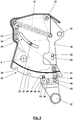
- the in Fig. 1 The pivot fitting 1 shown has a first bracket 2 for attachment to a side wall of a cabinet, not shown here.
- fastening holes 3 are provided in the essentially plate-shaped console.
- two equally long links 4 and 5 are mounted pivotably about equally spaced horizontally extending link pivot axes 6 and 7.
- the links 4 and 5 are on a second bracket 10 via further horizontal link pivot axes 8 and 9 pivoted.
- On or in the second bracket 10 are a fastening contour 11 and fastening holes 13 for fastening to a side wall of a swivel box of the cabinet, not shown here, and a stop 14 for the handlebar 5 in the FIG Fig.
- the illustrated starting position of the swivel fitting 1 and a stop 12 for the handlebar 4 are formed in a position pivoted to the maximum from the starting position. From the starting position, the bracket 10 can be pivoted downward to the left with respect to the bracket 2 along an arc around the handlebar pivot axis 6 until the handlebar strikes the stop 12.
- the console 10 is guided in parallel with respect to the console 2 by the handlebars 4 and 5.
- a support spring 15 is provided. One end 16 of the support spring 15 is supported on the console 2. With its other end 17, the support spring engages a point of application 18 on a tensioning lever 19 of an adjusting device 20.
- the tensioning lever 19 is mounted pivotably about a horizontal lever pivot axis 21 on a force transmission lever 22.
- the force transmission lever 22 is mounted on the bracket 2 so as to be pivotable about the handlebar pivot axis 6.
- the force transmission lever 22 rests against the console 2 via a stop 23 under the action of the pretensioned support spring 15.
- the link 4 reaches a minimum pivot position when pivoting about the link pivot axis 6, in which it points approximately vertically upwards, it strikes a stop 24 on the power transmission lever 22 and takes it with it during its further pivoting movement to the left and bottom.
- the spring force of the support spring 15 then acts on the link 4 via the tensioning lever 19, the force transmission lever 22 and the stop 24, so that it partially supports the weight force acting on the bracket 10.
- a lever arm can be adjusted around the handlebar pivot axis 6, via which the support spring 15 acts on the handlebar 4.
- the bias of the support spring 15 is also varied. Specifically shows Fig. 1 with a solid line a pivot position of the clamping lever 19 in which the lever arm via which the support spring 15 acts on the link 4, ie the distance between the point of application 18 and the link pivot axis 6 is greatest. At the same time, the bias of the support spring 15 is the smallest. Shows with dashed line Fig.
- a damping device 25 for the pivoting movement of the console 10 relative to the console 2 is provided between the console 2 and the handlebar 5, which in connection with Fig. 3 will be explained in more detail.
- the handlebar 5 has an extension 26 extending beyond the handlebar pivot axis 7, at the free end of which a synchronization rod 27 which is perpendicular to the plane of the drawing of Fig. 1 runs, is rigidly connected. Via the synchronization rod 27, the control arm guide with the consoles 2 and 10 and the control arms 4 and 5 is shown in FIG Fig.
- Fig. 2 shows the clamping lever 19 with the point of application 18 and the pivot axis 21 as well as the force transmission lever 22 with the stops 23 and 24 of the adjusting device 20 in a separate illustration.
- the power transmission lever 22 is designed like a housing. It has an elongated hole 29 running on an arc around the lever pivot axis 21, into which a bolt 30 of the tensioning lever 19 engages and which thus limits the pivoting movement of the tensioning lever 19 relative to the force transmission lever 22.
- a counter spring 31 is supported on the force transmission lever 22, while its other end engages the tensioning lever 19.
- the counter spring 31 partially compensates for the bias of the support spring 15 when the setting device 10 is adjusted. The setting is made without tools.
- a locking element 32 is guided radially to the lever pivot axis 21 on the tensioning lever 19 via elongated holes 33 and engaging bolts 34, which also include the locking element 32, against the force of a locking spring 35 so as to be linearly displaceable to a limited extent.
- the locking element 32 can be pulled out of one of here four recesses 36 following one another in the circumferential direction around the lever pivot axis 21 by pulling a handle 37 away from the lever pivot axis 21.
- the clamping lever 19 can be pivoted and locked in a different pivoting position, the locking element 32 engaging in another recess 36.
- This other pivot position corresponds to another lever arm, via which the spring force of the support spring 15 on the link 4 according to FIG Fig.
- Fig. 3 shows the damping device 25 in a separate illustration.
- the damping device 25 has a base 38 fastened to the console 2 and a rotor 39 which can be pivoted about the handlebar pivot axis 7 relative to the base and has a guide 40 for the rotationally fixed coupling to the handlebar 5.
- the base 38 is provided with a ring gear segment 41 which meshes with a gear 42 which is non-rotatably coupled to a rotary brake 44 rotating about an axis of rotation 43 relative to the rotor 39.
- a double-acting stop damper 45 is linearly guided in the base 38 and is compressed in one handlebar pivoting direction about the handlebar pivot axis 7 between a handlebar stop 46 on the rotor 39 and a console stop 47 on the base 38.
- the damper 45 is compressed between another bracket stop 48 and a driver end 49 of a driver 50, the other driver end 51 of which engages in an elongated hole 52 in the rotor 39 and is taken along by the rotor when the driver end 51 strikes against the edge of the elongated hole 52.
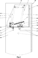
- Fig. 4 shows the upper area of a cabinet 55, in the body 56 of which a swivel box 57 is mounted via the swivel fitting 1. Even if in Fig. 4 while only one link guide 28 of the swivel fitting 1 is visible, a first bracket 2 is attached to both side walls 58 of the body 56 and the corresponding second brackets 10 of two link guides 28 are attached to both side walls 59 of the pivot box 57.
- the two handlebar guides 28 are designed essentially mirror-symmetrically to a vertical center plane of the cabinet 55, with different parts of the two handlebar guides 28 being able to be identical parts that are used in both handlebar guides 28.
- the console 10, together with the adjacent areas of the handlebars 4 and 5 of both handlebar guides 28, is covered with a cover 60 as protection against trapping.
- the handlebar guides are also in their starting position, as they are except for a slightly different pivot position of the clamping lever 19 in Fig. 1 is shown.
- the adjusting device 20 and the Damping device 25 are in exactly the starting positions as they are in the Fig. 2 and 3 are shown.
- the adjusting device 20 is provided in the area of the lower front handlebar pivot axis 7, ie the handlebar pivot axis between the front handlebar 4 and the first bracket 2 on the side wall 58, the pivoting position of the tensioning lever 19 on both handlebar guides 28 of the pivot fitting can be adjusted by engaging the handle 37 1 can easily be adjusted.
- the handle 37 is not more difficult to reach than the swivel box 57.
- the synchronization rod 27, on the other hand, is not in the area of the interior of the cabinet 55 in which there is a risk of a collision, especially since its range of motion can be delimited by internal elements 61 of the cabinet 55.
- Fig. 5 shows part of the body 56 of the cabinet 55 and the swivel box 57 pivoted out of it. Through the cover 60 is shown in the side view Fig. 5 the handlebar guide 28 facing the viewer is also not visible.
- the adjusting device 20 and the damping device 25 are by pivoting the power transmission lever 22 with the front link 4 about the handlebar pivot axis 6 or its rotor 39 with the handlebar 5 about the handlebar pivot axis 7 from their in the Fig. 2 and 3 initial positions shown pivoted out, with the pivoting of the power transmission lever 22 and the tensioning lever 19 connected to it, the support spring 15 was tensioned.
- the spring force of the tensioned support spring 15 acts via the distance between its point of application 18 on the tensioning lever 19 and the handlebar pivot axis 6 on the handlebar 4 and thus supports part of the weight of the pivot box 57 and objects arranged therein.
- the link 4 strikes the bracket 10 via the stop 12.
Landscapes
- Engineering & Computer Science (AREA)
- Mechanical Engineering (AREA)
- Mechanical Control Devices (AREA)
Priority Applications (1)
| Application Number | Priority Date | Filing Date | Title |
|---|---|---|---|
| EP19174848.2A EP3738466B1 (fr) | 2019-05-16 | 2019-05-16 | Ferrure pivotante destiné au logement pivotant d'un composant et armoire dotée d'une telle ferrure pivotante |
Applications Claiming Priority (1)
| Application Number | Priority Date | Filing Date | Title |
|---|---|---|---|
| EP19174848.2A EP3738466B1 (fr) | 2019-05-16 | 2019-05-16 | Ferrure pivotante destiné au logement pivotant d'un composant et armoire dotée d'une telle ferrure pivotante |
Publications (2)
| Publication Number | Publication Date |
|---|---|
| EP3738466A1 true EP3738466A1 (fr) | 2020-11-18 |
| EP3738466B1 EP3738466B1 (fr) | 2021-12-22 |
Family
ID=66589299
Family Applications (1)
| Application Number | Title | Priority Date | Filing Date |
|---|---|---|---|
| EP19174848.2A Active EP3738466B1 (fr) | 2019-05-16 | 2019-05-16 | Ferrure pivotante destiné au logement pivotant d'un composant et armoire dotée d'une telle ferrure pivotante |
Country Status (1)
| Country | Link |
|---|---|
| EP (1) | EP3738466B1 (fr) |
Cited By (1)
| Publication number | Priority date | Publication date | Assignee | Title |
|---|---|---|---|---|
| CN113080622A (zh) * | 2021-04-28 | 2021-07-09 | 中山市高美佳厨卫配件有限公司 | 一种电动智能升降收纳机构 |
Families Citing this family (1)
| Publication number | Priority date | Publication date | Assignee | Title |
|---|---|---|---|---|
| WO2024013243A1 (fr) * | 2022-07-13 | 2024-01-18 | F. Hoffmann-La Roche Ag | Dispositif de mécanisme de porte pour porte d'un appareil de transport pour transporter un porte-récipient d'échantillon |
Citations (5)
| Publication number | Priority date | Publication date | Assignee | Title |
|---|---|---|---|---|
| DE19617657A1 (de) * | 1996-05-03 | 1997-11-06 | Daimler Benz Aerospace Airbus | Vorrichtung zum Führen einer absenkbaren Schale für eine Überkopf-Gepäckablage, insbesondere in einem Passagierflugzeug |
| EP1820420A1 (fr) | 2006-02-16 | 2007-08-22 | Peka-Metall Ag | Elément d'armoire encastré pour rangement |
| EP2093361A2 (fr) * | 2008-02-25 | 2009-08-26 | Heinrich J. Kesseböhmer KG | Dispositif de fixation |
| WO2018071930A1 (fr) * | 2016-10-17 | 2018-04-26 | Julius Blum Gmbh | Dispositif d'entraînement pour meuble |
| DE102017114774A1 (de) * | 2017-07-03 | 2019-01-03 | Hettich-Oni Gmbh & Co. Kg | Klappenbeschlag und Möbel |
Family Cites Families (1)
| Publication number | Priority date | Publication date | Assignee | Title |
|---|---|---|---|---|
| DE60041326D1 (de) * | 2000-05-12 | 2009-02-26 | Antonio Giovannetti | Federantriebsvorrichtung für Türen, mit regelbarem Hebelarm der Feder |
-
2019
- 2019-05-16 EP EP19174848.2A patent/EP3738466B1/fr active Active
Patent Citations (5)
| Publication number | Priority date | Publication date | Assignee | Title |
|---|---|---|---|---|
| DE19617657A1 (de) * | 1996-05-03 | 1997-11-06 | Daimler Benz Aerospace Airbus | Vorrichtung zum Führen einer absenkbaren Schale für eine Überkopf-Gepäckablage, insbesondere in einem Passagierflugzeug |
| EP1820420A1 (fr) | 2006-02-16 | 2007-08-22 | Peka-Metall Ag | Elément d'armoire encastré pour rangement |
| EP2093361A2 (fr) * | 2008-02-25 | 2009-08-26 | Heinrich J. Kesseböhmer KG | Dispositif de fixation |
| WO2018071930A1 (fr) * | 2016-10-17 | 2018-04-26 | Julius Blum Gmbh | Dispositif d'entraînement pour meuble |
| DE102017114774A1 (de) * | 2017-07-03 | 2019-01-03 | Hettich-Oni Gmbh & Co. Kg | Klappenbeschlag und Möbel |
Cited By (1)
| Publication number | Priority date | Publication date | Assignee | Title |
|---|---|---|---|---|
| CN113080622A (zh) * | 2021-04-28 | 2021-07-09 | 中山市高美佳厨卫配件有限公司 | 一种电动智能升降收纳机构 |
Also Published As
| Publication number | Publication date |
|---|---|
| EP3738466B1 (fr) | 2021-12-22 |
Similar Documents
| Publication | Publication Date | Title |
|---|---|---|
| EP3612700B1 (fr) | Paroi de meuble avec un clapet et un corps de meuble et meuble avec une telle paroi de meuble | |
| EP3087866B1 (fr) | Armature pour une armoire angulaire et armoire angulaire dotée d'une armature | |
| EP2527576B1 (fr) | Dispositif de déplacement pour éléments de séparation maintenus de manière rotative et élément de mobilier | |
| EP2093361B1 (fr) | Dispositif de fixation | |
| EP3198097B1 (fr) | Charnière pour meubles | |
| WO2006113953A1 (fr) | Meuble en forme de placard | |
| EP2250929A1 (fr) | Elément d'armoire doté d'un élément de sortie rétractable | |
| EP2143862B1 (fr) | Vitre orientable parallèle | |
| DE102016104778B4 (de) | Türantrieb mit Haupt- und Hilfsantrieb | |
| EP3738466B1 (fr) | Ferrure pivotante destiné au logement pivotant d'un composant et armoire dotée d'une telle ferrure pivotante | |
| EP4532878B1 (fr) | Dispositif coulissant doté d'un profilé de montage et unité fonctionnelle | |
| EP3335591B1 (fr) | Dispositif d'arrêt à plusieurs reprises pour une ferrure d'arrêt pour un châssis, châssis et tiroir | |
| EP3547876B1 (fr) | Ferrure destinée au logement mobile commandé par roulement d'une étagère dans un élément d'angle | |
| EP4330503A1 (fr) | Système d'entraînement de meuble pour une pièce de meuble mobile | |
| DE102017126368A1 (de) | Möbelplatte mit einem Klappenbeschlag und Möbelkorpus sowie Möbel mit einer derartigen Möbelplatte | |
| EP4286633A1 (fr) | Dispositif coulissant doté d'un profilé de montage et unité fonctionnelle | |
| EP3276113A1 (fr) | Charnière de porte pour un pare-douche | |
| EP0670406B1 (fr) | Dispositif de limitation d'ouverture pour vantaux de portes | |
| EP2511463A1 (fr) | Fenêtre, porte ou analogue pourvue d'un dispositif d'amortissement | |
| EP2362048B1 (fr) | Appareil ménager, notamment four de cuisson | |
| EP3278689A1 (fr) | Armature pour une armoire angulaire | |
| DE102014104743B4 (de) | Höhenverstelleinheit für ein Tragarmsystem und ein entsprechendes Tragarmsystem | |
| EP3335592B1 (fr) | Dispositif d'arrêt pour une ferrure d'arrêt pour un châssis et châssis pourvu de ferrure d'arrêt | |
| DE102016108676A1 (de) | Scharniereinrichtung | |
| EP3156993A1 (fr) | Dispositif de présentation |
Legal Events
| Date | Code | Title | Description |
|---|---|---|---|
| PUAI | Public reference made under article 153(3) epc to a published international application that has entered the european phase |
Free format text: ORIGINAL CODE: 0009012 |
|
| STAA | Information on the status of an ep patent application or granted ep patent |
Free format text: STATUS: EXAMINATION IS IN PROGRESS |
|
| 17P | Request for examination filed |
Effective date: 20200107 |
|
| AK | Designated contracting states |
Kind code of ref document: A1 Designated state(s): AL AT BE BG CH CY CZ DE DK EE ES FI FR GB GR HR HU IE IS IT LI LT LU LV MC MK MT NL NO PL PT RO RS SE SI SK SM TR |
|
| AX | Request for extension of the european patent |
Extension state: BA ME |
|
| RBV | Designated contracting states (corrected) |
Designated state(s): AL AT BE BG CH CY CZ DE DK EE ES FI FR GB GR HR HU IE IS IT LI LT LU LV MC MK MT NL NO PL PT RO RS SE SI SK SM TR |
|
| GRAP | Despatch of communication of intention to grant a patent |
Free format text: ORIGINAL CODE: EPIDOSNIGR1 |
|
| STAA | Information on the status of an ep patent application or granted ep patent |
Free format text: STATUS: GRANT OF PATENT IS INTENDED |
|
| INTG | Intention to grant announced |
Effective date: 20210726 |
|
| GRAS | Grant fee paid |
Free format text: ORIGINAL CODE: EPIDOSNIGR3 |
|
| GRAA | (expected) grant |
Free format text: ORIGINAL CODE: 0009210 |
|
| STAA | Information on the status of an ep patent application or granted ep patent |
Free format text: STATUS: THE PATENT HAS BEEN GRANTED |
|
| AK | Designated contracting states |
Kind code of ref document: B1 Designated state(s): AL AT BE BG CH CY CZ DE DK EE ES FI FR GB GR HR HU IE IS IT LI LT LU LV MC MK MT NL NO PL PT RO RS SE SI SK SM TR |
|
| REG | Reference to a national code |
Ref country code: GB Ref legal event code: FG4D Free format text: NOT ENGLISH |
|
| REG | Reference to a national code |
Ref country code: CH Ref legal event code: EP |
|
| REG | Reference to a national code |
Ref country code: DE Ref legal event code: R096 Ref document number: 502019003036 Country of ref document: DE |
|
| REG | Reference to a national code |
Ref country code: AT Ref legal event code: REF Ref document number: 1456513 Country of ref document: AT Kind code of ref document: T Effective date: 20220115 |
|
| REG | Reference to a national code |
Ref country code: IE Ref legal event code: FG4D Free format text: LANGUAGE OF EP DOCUMENT: GERMAN |
|
| REG | Reference to a national code |
Ref country code: SE Ref legal event code: TRGR |
|
| REG | Reference to a national code |
Ref country code: LT Ref legal event code: MG9D |
|
| PG25 | Lapsed in a contracting state [announced via postgrant information from national office to epo] |
Ref country code: RS Free format text: LAPSE BECAUSE OF FAILURE TO SUBMIT A TRANSLATION OF THE DESCRIPTION OR TO PAY THE FEE WITHIN THE PRESCRIBED TIME-LIMIT Effective date: 20211222 Ref country code: LT Free format text: LAPSE BECAUSE OF FAILURE TO SUBMIT A TRANSLATION OF THE DESCRIPTION OR TO PAY THE FEE WITHIN THE PRESCRIBED TIME-LIMIT Effective date: 20211222 Ref country code: FI Free format text: LAPSE BECAUSE OF FAILURE TO SUBMIT A TRANSLATION OF THE DESCRIPTION OR TO PAY THE FEE WITHIN THE PRESCRIBED TIME-LIMIT Effective date: 20211222 Ref country code: BG Free format text: LAPSE BECAUSE OF FAILURE TO SUBMIT A TRANSLATION OF THE DESCRIPTION OR TO PAY THE FEE WITHIN THE PRESCRIBED TIME-LIMIT Effective date: 20220322 |
|
| REG | Reference to a national code |
Ref country code: NL Ref legal event code: MP Effective date: 20211222 |
|
| PG25 | Lapsed in a contracting state [announced via postgrant information from national office to epo] |
Ref country code: NO Free format text: LAPSE BECAUSE OF FAILURE TO SUBMIT A TRANSLATION OF THE DESCRIPTION OR TO PAY THE FEE WITHIN THE PRESCRIBED TIME-LIMIT Effective date: 20220322 Ref country code: LV Free format text: LAPSE BECAUSE OF FAILURE TO SUBMIT A TRANSLATION OF THE DESCRIPTION OR TO PAY THE FEE WITHIN THE PRESCRIBED TIME-LIMIT Effective date: 20211222 Ref country code: HR Free format text: LAPSE BECAUSE OF FAILURE TO SUBMIT A TRANSLATION OF THE DESCRIPTION OR TO PAY THE FEE WITHIN THE PRESCRIBED TIME-LIMIT Effective date: 20211222 Ref country code: GR Free format text: LAPSE BECAUSE OF FAILURE TO SUBMIT A TRANSLATION OF THE DESCRIPTION OR TO PAY THE FEE WITHIN THE PRESCRIBED TIME-LIMIT Effective date: 20220323 |
|
| PG25 | Lapsed in a contracting state [announced via postgrant information from national office to epo] |
Ref country code: NL Free format text: LAPSE BECAUSE OF FAILURE TO SUBMIT A TRANSLATION OF THE DESCRIPTION OR TO PAY THE FEE WITHIN THE PRESCRIBED TIME-LIMIT Effective date: 20211222 |
|
| PG25 | Lapsed in a contracting state [announced via postgrant information from national office to epo] |
Ref country code: SM Free format text: LAPSE BECAUSE OF FAILURE TO SUBMIT A TRANSLATION OF THE DESCRIPTION OR TO PAY THE FEE WITHIN THE PRESCRIBED TIME-LIMIT Effective date: 20211222 Ref country code: SK Free format text: LAPSE BECAUSE OF FAILURE TO SUBMIT A TRANSLATION OF THE DESCRIPTION OR TO PAY THE FEE WITHIN THE PRESCRIBED TIME-LIMIT Effective date: 20211222 Ref country code: RO Free format text: LAPSE BECAUSE OF FAILURE TO SUBMIT A TRANSLATION OF THE DESCRIPTION OR TO PAY THE FEE WITHIN THE PRESCRIBED TIME-LIMIT Effective date: 20211222 Ref country code: PT Free format text: LAPSE BECAUSE OF FAILURE TO SUBMIT A TRANSLATION OF THE DESCRIPTION OR TO PAY THE FEE WITHIN THE PRESCRIBED TIME-LIMIT Effective date: 20220422 Ref country code: ES Free format text: LAPSE BECAUSE OF FAILURE TO SUBMIT A TRANSLATION OF THE DESCRIPTION OR TO PAY THE FEE WITHIN THE PRESCRIBED TIME-LIMIT Effective date: 20211222 Ref country code: EE Free format text: LAPSE BECAUSE OF FAILURE TO SUBMIT A TRANSLATION OF THE DESCRIPTION OR TO PAY THE FEE WITHIN THE PRESCRIBED TIME-LIMIT Effective date: 20211222 Ref country code: CZ Free format text: LAPSE BECAUSE OF FAILURE TO SUBMIT A TRANSLATION OF THE DESCRIPTION OR TO PAY THE FEE WITHIN THE PRESCRIBED TIME-LIMIT Effective date: 20211222 |
|
| PG25 | Lapsed in a contracting state [announced via postgrant information from national office to epo] |
Ref country code: PL Free format text: LAPSE BECAUSE OF FAILURE TO SUBMIT A TRANSLATION OF THE DESCRIPTION OR TO PAY THE FEE WITHIN THE PRESCRIBED TIME-LIMIT Effective date: 20211222 |
|
| REG | Reference to a national code |
Ref country code: DE Ref legal event code: R097 Ref document number: 502019003036 Country of ref document: DE |
|
| PG25 | Lapsed in a contracting state [announced via postgrant information from national office to epo] |
Ref country code: IS Free format text: LAPSE BECAUSE OF FAILURE TO SUBMIT A TRANSLATION OF THE DESCRIPTION OR TO PAY THE FEE WITHIN THE PRESCRIBED TIME-LIMIT Effective date: 20220422 |
|
| PLBE | No opposition filed within time limit |
Free format text: ORIGINAL CODE: 0009261 |
|
| STAA | Information on the status of an ep patent application or granted ep patent |
Free format text: STATUS: NO OPPOSITION FILED WITHIN TIME LIMIT |
|
| PG25 | Lapsed in a contracting state [announced via postgrant information from national office to epo] |
Ref country code: DK Free format text: LAPSE BECAUSE OF FAILURE TO SUBMIT A TRANSLATION OF THE DESCRIPTION OR TO PAY THE FEE WITHIN THE PRESCRIBED TIME-LIMIT Effective date: 20211222 Ref country code: AL Free format text: LAPSE BECAUSE OF FAILURE TO SUBMIT A TRANSLATION OF THE DESCRIPTION OR TO PAY THE FEE WITHIN THE PRESCRIBED TIME-LIMIT Effective date: 20211222 |
|
| 26N | No opposition filed |
Effective date: 20220923 |
|
| REG | Reference to a national code |
Ref country code: BE Ref legal event code: MM Effective date: 20220531 |
|
| PG25 | Lapsed in a contracting state [announced via postgrant information from national office to epo] |
Ref country code: MC Free format text: LAPSE BECAUSE OF FAILURE TO SUBMIT A TRANSLATION OF THE DESCRIPTION OR TO PAY THE FEE WITHIN THE PRESCRIBED TIME-LIMIT Effective date: 20211222 Ref country code: LU Free format text: LAPSE BECAUSE OF NON-PAYMENT OF DUE FEES Effective date: 20220516 |
|
| PG25 | Lapsed in a contracting state [announced via postgrant information from national office to epo] |
Ref country code: SI Free format text: LAPSE BECAUSE OF FAILURE TO SUBMIT A TRANSLATION OF THE DESCRIPTION OR TO PAY THE FEE WITHIN THE PRESCRIBED TIME-LIMIT Effective date: 20211222 |
|
| PG25 | Lapsed in a contracting state [announced via postgrant information from national office to epo] |
Ref country code: IE Free format text: LAPSE BECAUSE OF NON-PAYMENT OF DUE FEES Effective date: 20220516 |
|
| PG25 | Lapsed in a contracting state [announced via postgrant information from national office to epo] |
Ref country code: BE Free format text: LAPSE BECAUSE OF NON-PAYMENT OF DUE FEES Effective date: 20220531 |
|
| P01 | Opt-out of the competence of the unified patent court (upc) registered |
Effective date: 20230528 |
|
| PG25 | Lapsed in a contracting state [announced via postgrant information from national office to epo] |
Ref country code: MK Free format text: LAPSE BECAUSE OF FAILURE TO SUBMIT A TRANSLATION OF THE DESCRIPTION OR TO PAY THE FEE WITHIN THE PRESCRIBED TIME-LIMIT Effective date: 20211222 Ref country code: CY Free format text: LAPSE BECAUSE OF FAILURE TO SUBMIT A TRANSLATION OF THE DESCRIPTION OR TO PAY THE FEE WITHIN THE PRESCRIBED TIME-LIMIT Effective date: 20211222 |
|
| PG25 | Lapsed in a contracting state [announced via postgrant information from national office to epo] |
Ref country code: HU Free format text: LAPSE BECAUSE OF FAILURE TO SUBMIT A TRANSLATION OF THE DESCRIPTION OR TO PAY THE FEE WITHIN THE PRESCRIBED TIME-LIMIT; INVALID AB INITIO Effective date: 20190516 |
|
| PG25 | Lapsed in a contracting state [announced via postgrant information from national office to epo] |
Ref country code: MT Free format text: LAPSE BECAUSE OF FAILURE TO SUBMIT A TRANSLATION OF THE DESCRIPTION OR TO PAY THE FEE WITHIN THE PRESCRIBED TIME-LIMIT Effective date: 20211222 |
|
| PGFP | Annual fee paid to national office [announced via postgrant information from national office to epo] |
Ref country code: DE Payment date: 20250402 Year of fee payment: 7 |
|
| PGFP | Annual fee paid to national office [announced via postgrant information from national office to epo] |
Ref country code: IT Payment date: 20250530 Year of fee payment: 7 |
|
| PGFP | Annual fee paid to national office [announced via postgrant information from national office to epo] |
Ref country code: FR Payment date: 20250523 Year of fee payment: 7 |
|
| PGFP | Annual fee paid to national office [announced via postgrant information from national office to epo] |
Ref country code: CH Payment date: 20250601 Year of fee payment: 7 |
|
| PGFP | Annual fee paid to national office [announced via postgrant information from national office to epo] |
Ref country code: AT Payment date: 20250519 Year of fee payment: 7 |
|
| PGFP | Annual fee paid to national office [announced via postgrant information from national office to epo] |
Ref country code: SE Payment date: 20250522 Year of fee payment: 7 |
|
| PG25 | Lapsed in a contracting state [announced via postgrant information from national office to epo] |
Ref country code: TR Free format text: LAPSE BECAUSE OF FAILURE TO SUBMIT A TRANSLATION OF THE DESCRIPTION OR TO PAY THE FEE WITHIN THE PRESCRIBED TIME-LIMIT Effective date: 20211222 |
|
| PGFP | Annual fee paid to national office [announced via postgrant information from national office to epo] |
Ref country code: GB Payment date: 20260324 Year of fee payment: 8 |