EP3738470A1 - Dispositif coulissant pour tiroir - Google Patents
Dispositif coulissant pour tiroir Download PDFInfo
- Publication number
- EP3738470A1 EP3738470A1 EP18900292.6A EP18900292A EP3738470A1 EP 3738470 A1 EP3738470 A1 EP 3738470A1 EP 18900292 A EP18900292 A EP 18900292A EP 3738470 A1 EP3738470 A1 EP 3738470A1
- Authority
- EP
- European Patent Office
- Prior art keywords
- slide
- ball
- rail
- sliding device
- drawer
- Prior art date
- Legal status (The legal status is an assumption and is not a legal conclusion. Google has not performed a legal analysis and makes no representation as to the accuracy of the status listed.)
- Withdrawn
Links
- 230000000712 assembly Effects 0.000 claims abstract description 4
- 238000000429 assembly Methods 0.000 claims abstract description 4
- 238000005096 rolling process Methods 0.000 claims description 53
- 239000000463 material Substances 0.000 claims description 17
- 230000003014 reinforcing effect Effects 0.000 abstract description 6
- 230000035939 shock Effects 0.000 abstract description 2
- 238000010586 diagram Methods 0.000 description 24
- XEEYBQQBJWHFJM-UHFFFAOYSA-N Iron Chemical compound [Fe] XEEYBQQBJWHFJM-UHFFFAOYSA-N 0.000 description 16
- 229910052742 iron Inorganic materials 0.000 description 8
- 229920006324 polyoxymethylene Polymers 0.000 description 6
- 229930182556 Polyacetal Natural products 0.000 description 5
- 239000011347 resin Substances 0.000 description 5
- 229920005989 resin Polymers 0.000 description 5
- 230000000052 comparative effect Effects 0.000 description 3
- 239000002184 metal Substances 0.000 description 2
- 229910052751 metal Inorganic materials 0.000 description 2
- 230000000694 effects Effects 0.000 description 1
- 230000004048 modification Effects 0.000 description 1
- 238000012986 modification Methods 0.000 description 1
- 238000000926 separation method Methods 0.000 description 1
Images




Classifications
-
- A—HUMAN NECESSITIES
- A47—FURNITURE; DOMESTIC ARTICLES OR APPLIANCES; COFFEE MILLS; SPICE MILLS; SUCTION CLEANERS IN GENERAL
- A47B—TABLES; DESKS; OFFICE FURNITURE; CABINETS; DRAWERS; GENERAL DETAILS OF FURNITURE
- A47B88/00—Drawers for tables, cabinets or like furniture; Guides for drawers
- A47B88/40—Sliding drawers; Slides or guides therefor
- A47B88/437—Rollers for slides or guides
-
- A—HUMAN NECESSITIES
- A47—FURNITURE; DOMESTIC ARTICLES OR APPLIANCES; COFFEE MILLS; SPICE MILLS; SUCTION CLEANERS IN GENERAL
- A47B—TABLES; DESKS; OFFICE FURNITURE; CABINETS; DRAWERS; GENERAL DETAILS OF FURNITURE
- A47B88/00—Drawers for tables, cabinets or like furniture; Guides for drawers
- A47B88/40—Sliding drawers; Slides or guides therefor
- A47B88/49—Sliding drawers; Slides or guides therefor with double extensible guides or parts
- A47B88/493—Sliding drawers; Slides or guides therefor with double extensible guides or parts with rollers, ball bearings, wheels, or the like
-
- A—HUMAN NECESSITIES
- A47—FURNITURE; DOMESTIC ARTICLES OR APPLIANCES; COFFEE MILLS; SPICE MILLS; SUCTION CLEANERS IN GENERAL
- A47B—TABLES; DESKS; OFFICE FURNITURE; CABINETS; DRAWERS; GENERAL DETAILS OF FURNITURE
- A47B88/00—Drawers for tables, cabinets or like furniture; Guides for drawers
- A47B88/40—Sliding drawers; Slides or guides therefor
- A47B88/473—Braking devices, e.g. linear or rotational dampers or friction brakes; Buffers; End stops
-
- A—HUMAN NECESSITIES
- A47—FURNITURE; DOMESTIC ARTICLES OR APPLIANCES; COFFEE MILLS; SPICE MILLS; SUCTION CLEANERS IN GENERAL
- A47B—TABLES; DESKS; OFFICE FURNITURE; CABINETS; DRAWERS; GENERAL DETAILS OF FURNITURE
- A47B2210/00—General construction of drawers, guides and guide devices
- A47B2210/0002—Guide construction for drawers
- A47B2210/0008—Guide construction for drawers having a roller on an intermediary slide rail between the cabinet rail and the drawer rail
-
- A—HUMAN NECESSITIES
- A47—FURNITURE; DOMESTIC ARTICLES OR APPLIANCES; COFFEE MILLS; SPICE MILLS; SUCTION CLEANERS IN GENERAL
- A47B—TABLES; DESKS; OFFICE FURNITURE; CABINETS; DRAWERS; GENERAL DETAILS OF FURNITURE
- A47B2210/00—General construction of drawers, guides and guide devices
- A47B2210/0002—Guide construction for drawers
- A47B2210/0029—Guide bearing means
- A47B2210/0032—Balls
-
- A—HUMAN NECESSITIES
- A47—FURNITURE; DOMESTIC ARTICLES OR APPLIANCES; COFFEE MILLS; SPICE MILLS; SUCTION CLEANERS IN GENERAL
- A47B—TABLES; DESKS; OFFICE FURNITURE; CABINETS; DRAWERS; GENERAL DETAILS OF FURNITURE
- A47B2210/00—General construction of drawers, guides and guide devices
- A47B2210/0002—Guide construction for drawers
- A47B2210/0029—Guide bearing means
- A47B2210/0032—Balls
- A47B2210/0035—Balls cages therefor, e.g. for telescopic slides
-
- A—HUMAN NECESSITIES
- A47—FURNITURE; DOMESTIC ARTICLES OR APPLIANCES; COFFEE MILLS; SPICE MILLS; SUCTION CLEANERS IN GENERAL
- A47B—TABLES; DESKS; OFFICE FURNITURE; CABINETS; DRAWERS; GENERAL DETAILS OF FURNITURE
- A47B2210/00—General construction of drawers, guides and guide devices
- A47B2210/0002—Guide construction for drawers
- A47B2210/0029—Guide bearing means
- A47B2210/0037—Rollers
-
- A—HUMAN NECESSITIES
- A47—FURNITURE; DOMESTIC ARTICLES OR APPLIANCES; COFFEE MILLS; SPICE MILLS; SUCTION CLEANERS IN GENERAL
- A47B—TABLES; DESKS; OFFICE FURNITURE; CABINETS; DRAWERS; GENERAL DETAILS OF FURNITURE
- A47B2210/00—General construction of drawers, guides and guide devices
- A47B2210/0002—Guide construction for drawers
- A47B2210/0064—Guide sequencing or synchronisation
- A47B2210/0067—Two slide synchronisation
-
- A—HUMAN NECESSITIES
- A47—FURNITURE; DOMESTIC ARTICLES OR APPLIANCES; COFFEE MILLS; SPICE MILLS; SUCTION CLEANERS IN GENERAL
- A47B—TABLES; DESKS; OFFICE FURNITURE; CABINETS; DRAWERS; GENERAL DETAILS OF FURNITURE
- A47B88/00—Drawers for tables, cabinets or like furniture; Guides for drawers
- A47B88/40—Sliding drawers; Slides or guides therefor
- A47B88/473—Braking devices, e.g. linear or rotational dampers or friction brakes; Buffers; End stops
- A47B88/477—Buffers; End stops
Definitions
- the present disclosure relates to a sliding device for a drawer, and more particularly, to a sliding device for a drawer capable of reinforcing rigidity while reducing noise during operation by mixing and using a plurality of slide balls having different tensile strengths.
- a sliding device for a drawer is provided between a main body and a storage body and is used so that the storage body is easily drawn out from or drawn into from the main body when the user opens and closes the storage body.
- the sliding device for the drawer is provided in a double-fold folding type and a triple-fold folding type.
- a fixed rail is fastened to the inner surface of the main body
- a movable rail is fastened to the outer surface of the storage body.
- an intermediate rail is provided between the fixed rail and the movable rail, and a plurality of slide balls are disposed between the intermediate rail and the fixed rail and between the intermediate rail and the movable rail to perform a rolling motion.
- the intermediate rail and the movable rail are supported by the fixed rail to slide together with the storage body.
- a conventional sliding device for a drawer uses slide balls made of the same materials.
- the slide ball made of metal or plastic is used.
- the present disclosure is intended to solve the above problems, and an object of the present disclosure is to provide a sliding device for a drawer capable of reinforcing rigidity while reducing noise during operation by mixing and using a plurality of slide balls having different tensile strengths.
- a sliding device for a drawer includes: a fixed rail fastened and fixed to a main body; a movable rail fastened and fixed to a storage body, and sliding on the fixed rail; an intermediate rail disposed between the fixed rail and the movable rail to guide the sliding movement of the movable rail; and ball assemblies disposed between the intermediate rail and the fixed rail and between the intermediate rail and the movable rail, respectively to slide, and provided with a plurality of slide balls having different tensile strengths, the slide ball having a large tensile strength being disposed at the outermost side thereof.
- the intermediate rail may include: a plate part disposed between the fixed rail and the movable rail; and contact parts provided at both sides of the plate part along the longitudinal direction, respectively, and formed with rolling surfaces so that the slide balls of the ball assembly are partially accommodated, and a plurality of rolling surfaces may be formed to be spaced apart from each other along the circumferential direction thereof at each of one side and the other side of the plate part.
- the ball assembly may include: a retainer provided in a ' ' shape, and formed with a plurality of through holes at regular intervals in the longitudinal direction at both ends and edges thereof; a first slide ball inserted into a first through hole formed in the end of one side of the retainer, and disposed on a first rolling surface formed to be curved at the edge of one side of the contact part; a second slide ball inserted into a second through hole formed in the edge of the retainer, and disposed on a second rolling surface formed to be curved at the edge of the other side of the contact part; and a third slide ball inserted into a third through hole formed in the end of the other side of the retainer, and disposed on a third rolling surface formed to be curved at the lower side of the second rolling surface.
- the retainer may have the first through hole and the third through hole which are provided on the same line, and also have the second through hole which is provided between the first through hole and the third through hole.
- first rolling surface, the second rolling surface, and the third rolling surface may be formed to be curved at the same diameters, and the first slide ball, the second slide ball, and the third slide ball may also be provided at the same diameters.
- first rolling surface and the second rolling surface may be formed to be curved at the same diameters
- third rolling surface may be formed to be curved at a larger diameter than that of the second rolling surface
- first slide ball and the second slide ball may be provided at the same diameters
- third slide ball may also be provided at a larger diameter than that of the second slide ball.
- the ball assembly may also have the slide balls disposed at both side ends which are larger in tensile strength than the slide balls located at the center side, among the plurality of first slide balls and third slide balls.
- the ball assembly may also have the slide balls disposed at both side ends which are larger in tensile strength than the slide balls located at the center side, among the plurality of second slide balls.
- the ball assembly may also have the slide balls having different tensile strengths whose difference is 400 MPa or more.
- the ball assembly may have the slide ball having a large tensile strength which is made of a material having the tensile strength of 405 to 2500 MPa, and also have the slide ball having a small tensile strength which is made of a material having the tensile strength of 5 to 150 MPa.
- the fixed rail and the movable rail may further include: stoppers formed to protrude from the inner circumferential surfaces of the fixed rail and the movable rail, and limiting the movement so that the ball assembly slides only within a predetermined region.
- the intermediate rail may further include: a stopper limiting the movement so that the ball assembly slides only within a predetermined region.
- the sliding device for the drawer according to the present disclosure may reduce noise using the slide ball having the low tensile strength as a whole, and reinforce rigidity using the slide ball having the large tensile strength in the portion to which the shock load is applied.
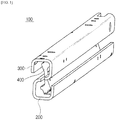
- FIGS. 1 to 3 are a perspective diagram, an exploded perspective diagram, and a side diagram schematically illustrating a sliding device for a drawer according to an exemplary embodiment of the present disclosure.
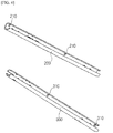
- FIG. 4 is a perspective diagram schematically illustrating a fixed rail and a movable rail excerpted from the sliding device for the drawer
- FIGS. 5 and 6 are a side diagram and a perspective diagram schematically illustrating an intermediate rail excerpted from the sliding device for the drawer
- FIG. 7 is a plane diagram schematically illustrating a retainer excerpted from the sliding device for the drawer.
- FIG. 8 is a diagram schematically illustrating a load state applied to the sliding device for the drawer
- FIG. 9 is a front diagram and a rear diagram schematically illustrating a state where the ball assembly is disposed on the intermediate rail in the sliding device for the drawer.
- a sliding device for a drawer 100 includes a fixed rail 200 fastened and fixed to a main body 10, a movable rail 300 fastened and fixed to a storage body 20 and sliding on the fixed rail 200, an intermediate rail 400 disposed between the fixed rail 200 and the movable rail 300 to guide the sliding movement of the movable rail 300, and ball assemblies 500 disposed between the intermediate rail 400 and the fixed rail 200 and between the intermediate rail 400 and the movable rail 300, respectively to move to be slidable and provided with a plurality of slide balls having different tensile strengths, the slide ball having a large tensile strength being disposed at the outermost portion thereof.
- the present disclosure may dispose a slide ball made of a material having a relatively small tensile strength at the center side of the sliding device, and a slide ball made of a material having a relatively large tensile strength at the outermost side thereof, thereby reducing noise during driving compared to a sliding device using only a slide ball made of a material having a large tensile strength, and reinforcing rigidity compared to a sliding device using only a slide ball made of a material having a small tensile strength.
- the fixed rail 200 is fastened to the inner surface of the main body 10 and fixed in position
- the movable rail 300 is fastened to the outer surface of the storage body 20 and provided to move to be slidable on the fixed rail 200 to draw into or draw out the storage body 20.
- the inner circumferential surfaces of the fixed rail 200 and the movable rail 300 are formed with a fixed rail stopper 210 and a movable rail stopper 310 which are formed to protrude inward, respectively to limit the movement so that the ball assembly 500 slides only within a predetermined region.
- a pair of the fixed rail stopper 210 and a pair of the movable rail stopper 310 are provided and are formed to be spaced apart from each other at regular intervals, respectively. According to such a configuration, the ball assembly 500 slides only between the fixed rail stoppers 210 and between the movable rail stoppers 310.
- the intermediate rail 400 includes a plate part 410 disposed between the fixed rail 200 and the movable rail 300, and contact parts 420 provided at both sides of the plate part 410 along the longitudinal direction and formed with rolling surfaces so that the slide ball of the ball assembly 500 is partially accommodated.
- three rolling surfaces are formed to be spaced apart from each other along the circumferential direction at each of one side and the other side of the plate part 410, and provided so that the plurality of slide balls roll and are in contact with the rolling surface.
- the contact parts 420 are formed at the upper side and the lower side of the plate part 410, and the contact part 420 formed at the upper side is formed to be reversely symmetrical to the contact part 420 formed at the lower side. That is, the three rolling surfaces are formed along the circumferential direction at the upper side of the plate part 410, and the three rolling surfaces are formed along the circumferential direction at the lower side of the plate part 410.
- the rolling surfaces are composed of a first rolling surface 421 formed to be curved at the edge of one side of the contact part 420, a second rolling surface 422 formed to be curved at the same diameter as the first rolling surface 421 at the edge of the other side of the contact part 420, and a third rolling surface 423 formed to be curved at a larger diameter than that of the second rolling surface 422 at the lower side of the second rolling surface 422. That is, the slide balls having the same diameters are disposed on the first rolling surface 421 and the second rolling surface 422, and the slide balls having a larger diameter are disposed on the third rolling surface 423.
- intermediate rail 400 is provided with an intermediate rail stopper 430 which limits the movement so that the ball assembly 500 slides only within a predetermined region.
- a pair of the intermediate rail stoppers 430 are provided and disposed to be spaced apart from each other at a regular interval, and formed to protrude from the plate part 410 toward the,first rolling surface 421. That is, the intermediate rail stoppers 430 are formed to have a separation distance longer than the length of the ball assembly 500, so that the ball assembly 500 is provided to move to be slidable between the intermediate rail stoppers 430.
- the intermediate rail stopper 430 formed at the upper side of the plate part 410 is formed to be inversely symmetrical to the intermediate rail stopper 430 formed at the lower side of the plate part 410. That is, the intermediate rail stopper 430 formed at the upper side of the plate part 410 is formed to be biased to the left side with respect to the drawing, and the intermediate rail stopper 430 formed at the lower side of the plate part 410 is formed to be biased to the right side with respect to the drawing.
- a gap between the intermediate rail stoppers 430 formed at the upper side of the plate part 410 and a gap between the intermediate rail stoppers 430 formed at the lower side of the plate part 410 may also be formed differently.
- the intermediate rail stopper 430 thus formed may limit the maximum drawn-out distance of the storage body by limiting the movement region of the ball assembly 500 together with the fixed rail stopper 210 and the movable rail stopper 310.
- the ball assembly 500 includes a retainer 510 provided in a ' ' shape and formed with a plurality of through holes at regular intervals in the longitudinal direction at both ends and edges, a first slide ball 520 inserted into a first through hole 511 formed in the end of one side of the retainer 510 and disposed on the first rolling surface 421, a second slide ball 530 inserted into a second through hole 512 formed at the edge of the retainer 510, provided at the same diameter as the first slide ball 520, and disposed on the second rolling surface 422, and a third slide ball 540 inserted into a third through hole 513 formed in the end of the other side of the retainer 510, provided to have a larger diameter than that of the second slide ball 530, and disposed on the third rolling surface 423.
- the retainer 510 has the first through holes 511 which are formed in the end of one side at regular intervals along the longitudinal direction, the second through holes 512 which are formed in the edge at regular intervals along the longitudinal direction, and the third through holes 513 which are formed in the end of the other side at regular intervals along the longitudinal direction.
- first through hole 511 and the third through hole 513 are provided on the same line, and the second through hole 512 is provided between the first through hole 511 and the third through hole 513.
- a load point may be dispersed and thus the load applied to the sliding device 100 for the drawer by the storage body may be dispersed, thereby reinforcing the rigidity of the sliding device for the drawer.
- the ball assembly 500 has the first slide ball 520 and the second slide ball 530 which are provided at the same diameters, and the third slide ball 540 which is provided larger in diameter than the first slide ball 520.
- the third slide ball 540 and the third rolling surface 423 are provided to have a larger diameter than those of the first slide ball 520 and the first rolling surface 421, thereby increasing a rolling contact area of the third slide ball 540. Accordingly, the intensive load applied between the movable-rail 300 and the third slide ball 540 and between the third slide ball 540 and the third rolling surface 423 may be dispersed, thereby reducing wear and damage of the third slide ball 540.
- the ball assembly 500 has the slide balls 521, 541 disposed at both side ends of the plurality of first slide balls 520 and third slide balls 540 which are made of a material having the tensile strength larger than that of the slide balls 522, 542 located at the center side of the ball assembly 500.
- the ball assembly 500 may also be provided with the slide balls 531 disposed at both side ends of the plurality of second slide balls 530 having the tensile length larger than that of the slide ball 532 located at the center side of the ball assembly 500.
- the ball assembly 500 may be configured so that only the first and third slide balls 520, 540 of the first to third slide balls 520, 530, 540 have the slide balls 521, 541 located at both side ends which are made of a material having a large tensile strength, or all of the first to third slide balls 520, 530, 540 have the slide balls 521, 531, 541 located at both side ends which are made of a large tensile strength. Accordingly, it is possible to select the number of slide balls used made of a material having a large tensile strength in consideration of the required rigidity according to the use of the storage body.
- a material having a difference in tensile strength of 400 MPa or more among the slide balls having different tensile strengths may be selected and applied to the ball assembly 500.
- the slide ball having the large tensile strength may be made of a material having the tensile strength of 405 to 2500 MPa
- the slide ball having the small tensile strength may be made of a material having a tensile strength of 5 to 150 MPa.
- a slide ball made of iron having a tensile strength of 600 MPa and a slide ball made of polyacetal resin (POM) having a tensile strength of 100 MPa are used, and a comparison of noises generated in the sliding device in the case of using only the slide ball made of iron and the case of mixing and using the slide ball made of iron and the slide ball made of polyacetal resin is shown in Table below.
- POM polyacetal resin
- Example 1 for all of the first to third slide balls 520, 530, 540, the slide balls 521, 531, 541 located both side ends thereof used the slide balls made of iron, and the slide balls 522, 532, 542 located at the center side thereof used the slide balls made of polyacetal resin.
- Example 2 for only the first and third slide balls 520, 540, the slide balls 521, 541 located at both side ends used the slide balls made of iron, and the slide balls 522, 542 located at the center side and the second slide ball 530 used the slide balls made of polyacetal resin.
- Example 2 As shown in Table 1, in the Comparative Example, a noise of 4.4 dB was generated during operation, and in Example 1, a noise of 3.9 dB was generated, thereby improving the noise by 11%. In addition, in Example 2, it may be seen that a noise of 2.5 dB was generated, thereby improving the noise by 56%.
- the slide balls located at both side ends may use the slide ball made of a material having a relatively large tensile strength such as iron, thereby reinforcing rigidity
- the slide ball located at the center side may use the slide ball made of a material having a relatively low tensile strength such as polyacetal resin, thereby reducing the generation of noise, compared to the case where all of the slide balls use the slide balls made of iron.
- FIG. 10 is a diagram schematically illustrating a sliding device for a drawer according to another exemplary embodiment of the present disclosure.
- a sliding device for a drawer according to another exemplary embodiment of the present disclosure is provided to have the same configuration as the sliding device for the drawer according to the exemplary embodiment of the present disclosure described with reference to FIGS. 1 to 9 , and only a difference is that the first rolling surface, the second rolling surface, and the third rolling surface are formed to be curved at the same diameters and the first slide ball, the second slide ball, and the third slide ball are provided at the same diameters.
- the sliding device for the drawer according to another exemplary embodiment of the present disclosure is provided so that the first to third slide balls have the same diameters.
- FIG. 11 is a diagram schematically illustrating a sliding device for a drawer according to still another exemplary embodiment of the present disclosure.
- a sliding device for a drawer according to still another exemplary embodiment of the present disclosure is provided to have the same configuration as the sliding device for the drawer according to the exemplary embodiment of the present disclosure described with reference to FIGS. 1 to 9 , and a difference is the number of arrangements of the slide balls.
- the sliding device for the drawer may have the slide balls disposed on the contact part which are provided in a two-column state, or as illustrated in FIG. 11B , also have the slide balls disposed on the contact part which are provided in a four-column state.
Landscapes
- Drawers Of Furniture (AREA)
- Engineering & Computer Science (AREA)
- General Engineering & Computer Science (AREA)
- Mechanical Engineering (AREA)
Applications Claiming Priority (2)
| Application Number | Priority Date | Filing Date | Title |
|---|---|---|---|
| KR1020180003324A KR20190085332A (ko) | 2018-01-10 | 2018-01-10 | 서랍용 슬라이드 장치 |
| PCT/KR2018/016806 WO2019139290A1 (fr) | 2018-01-10 | 2018-12-28 | Dispositif coulissant pour tiroir |
Publications (2)
| Publication Number | Publication Date |
|---|---|
| EP3738470A1 true EP3738470A1 (fr) | 2020-11-18 |
| EP3738470A4 EP3738470A4 (fr) | 2021-10-06 |
Family
ID=67218634
Family Applications (1)
| Application Number | Title | Priority Date | Filing Date |
|---|---|---|---|
| EP18900292.6A Withdrawn EP3738470A4 (fr) | 2018-01-10 | 2018-12-28 | Dispositif coulissant pour tiroir |
Country Status (5)
| Country | Link |
|---|---|
| US (1) | US20210068540A1 (fr) |
| EP (1) | EP3738470A4 (fr) |
| KR (1) | KR20190085332A (fr) |
| CN (1) | CN213664408U (fr) |
| WO (1) | WO2019139290A1 (fr) |
Families Citing this family (7)
| Publication number | Priority date | Publication date | Assignee | Title |
|---|---|---|---|---|
| KR102428922B1 (ko) * | 2020-06-11 | 2022-08-04 | (주)세고스 | 슬라이드 장치 |
| CN111870069A (zh) * | 2020-08-25 | 2020-11-03 | 东莞市帝格五金制品有限公司 | 一种滑轨组件及包括其的柜子 |
| WO2022061687A1 (fr) * | 2020-09-25 | 2022-03-31 | 无锡海达尔精密滑轨股份有限公司 | Rail coulissant à billes |
| KR102450391B1 (ko) * | 2020-11-17 | 2022-10-04 | 케이비아이동국실업 주식회사 | 착탈구조를 가지는 슬라이딩형 글로브박스 |
| WO2023286888A1 (fr) * | 2021-07-15 | 2023-01-19 | (주)세고스 | Dispositif coulissant |
| KR20240156858A (ko) * | 2023-04-24 | 2024-10-31 | (주)세고스 | 슬라이드 장치 |
| KR102923826B1 (ko) * | 2024-01-11 | 2026-02-09 | (주)세고스 | 슬라이드 레일 조립체 및 이를 포함하는 인출 시스템 |
Family Cites Families (16)
| Publication number | Priority date | Publication date | Assignee | Title |
|---|---|---|---|---|
| DE3148933A1 (de) * | 1981-12-10 | 1983-06-23 | Kiekert GmbH & Co KG, 5628 Heiligenhaus | Teleskopschienensystem |
| US10593092B2 (en) * | 1990-12-07 | 2020-03-17 | Dennis J Solomon | Integrated 3D-D2 visual effects display |
| US5316389A (en) * | 1992-08-24 | 1994-05-31 | Knape & Vogt Manufacturing Company | Drawer slide assembly |
| US5417496A (en) * | 1994-03-01 | 1995-05-23 | General Devices Co., Inc. | Ball bearing retainer for telescoping slide assembly |
| DE29507916U1 (de) * | 1995-05-17 | 1995-08-10 | Paul Hettich Gmbh & Co., 32278 Kirchlengern | Schubkastenauszugsführung |
| KR100412405B1 (ko) * | 2001-11-01 | 2003-12-31 | 위니아만도 주식회사 | 서랍식 김치저장고의 가이드레일 구조 |
| KR200291086Y1 (ko) * | 2002-06-19 | 2002-10-09 | 정두영 | 서랍용 볼레일 |
| KR100897920B1 (ko) * | 2006-12-04 | 2009-05-18 | 박윤식 | 대 직경 볼이 장착된 슬라이드 |
| US8448592B2 (en) * | 2007-10-30 | 2013-05-28 | Ocean Server Technology, Inc. | External rescue and recovery devices and methods for underwater vehicles |
| WO2012022788A1 (fr) * | 2010-08-20 | 2012-02-23 | Paul Hettich Gmbh & Co. Kg | Glissière de tiroir |
| DE102010042180A1 (de) * | 2010-10-08 | 2012-04-12 | Schock Metallwerk Gmbh | Auszugführung |
| DE102012106751B4 (de) * | 2012-07-25 | 2026-03-19 | Paul Hettich Gmbh & Co. Kg | Auszugsführung für relativ zueinander bewegbare Möbelteile |
| KR101352439B1 (ko) | 2012-07-26 | 2014-01-20 | (주)세고스 | 서랍용 슬라이드 장치 |
| KR101641489B1 (ko) * | 2014-09-24 | 2016-07-21 | 엘지전자 주식회사 | 이동단말기 및 차량 |
| US20160167098A1 (en) * | 2014-12-10 | 2016-06-16 | Tai Cheer Industrial Co., Ltd. | Manufacturing method of sliding unit of sliding rail and structure thereof |
| CN105508422A (zh) * | 2016-01-27 | 2016-04-20 | 无锡海达尔精密滑轨股份有限公司 | 三排滚珠滑轨 |
-
2018
- 2018-01-10 KR KR1020180003324A patent/KR20190085332A/ko not_active Ceased
- 2018-12-28 EP EP18900292.6A patent/EP3738470A4/fr not_active Withdrawn
- 2018-12-28 US US16/959,913 patent/US20210068540A1/en not_active Abandoned
- 2018-12-28 CN CN201890001463.1U patent/CN213664408U/zh not_active Expired - Fee Related
- 2018-12-28 WO PCT/KR2018/016806 patent/WO2019139290A1/fr not_active Ceased
Also Published As
| Publication number | Publication date |
|---|---|
| EP3738470A4 (fr) | 2021-10-06 |
| US20210068540A1 (en) | 2021-03-11 |
| CN213664408U (zh) | 2021-07-13 |
| WO2019139290A1 (fr) | 2019-07-18 |
| KR20190085332A (ko) | 2019-07-18 |
Similar Documents
| Publication | Publication Date | Title |
|---|---|---|
| EP3738470A1 (fr) | Dispositif coulissant pour tiroir | |
| US8167388B2 (en) | Pull-out guide assembly for a drawer | |
| EP2611332B1 (fr) | Ensemble de guidage d'extraction pour tiroir | |
| EP4233641A2 (fr) | Élément de meuble | |
| EP2497682A1 (fr) | Dispositif de coulissement de siège pour véhicule | |
| US20140318422A1 (en) | Linear Guide | |
| US10583753B2 (en) | Roller guide | |
| US8308251B2 (en) | Elastic force adjustment device for slide assembly | |
| KR102598407B1 (ko) | 슬라이딩형 콘솔박스 | |
| GB2028109A (en) | Telescopic drawer slides | |
| EP0868866A2 (fr) | Ensemble de guidage pour le coulissement d'un tiroir | |
| JP2016534792A (ja) | 引出しガイド | |
| US20220053933A1 (en) | Slide Rail Assembly | |
| US20050196081A1 (en) | Linear guide bearing apparatus | |
| US4037885A (en) | Withdrawal guide for drawers or the like | |
| US10391906B2 (en) | Sliding mechanism for a vehicle floor console and a floor console sliding armrest assembly | |
| CA2951981C (fr) | Guidage telescopique pour parties de meubles mobiles les unes par rapport aux autres | |
| US20090243450A1 (en) | Slide rail assembly | |
| US20070049356A1 (en) | Slide module for portable terminal | |
| CN101287394A (zh) | 抽屉抽出导向装置 | |
| US20110081104A1 (en) | Slide assembly | |
| EP2716182B1 (fr) | Guidage d'extraction pour un élément de meuble pouvant être extrait d'un corps de meuble | |
| KR100897920B1 (ko) | 대 직경 볼이 장착된 슬라이드 | |
| CN205446394U (zh) | 一种圆弧形且移动件为板体型的滚珠滑轨 | |
| CN207855383U (zh) | 一种钢珠滑轨按压反弹器 |
Legal Events
| Date | Code | Title | Description |
|---|---|---|---|
| STAA | Information on the status of an ep patent application or granted ep patent |
Free format text: STATUS: THE INTERNATIONAL PUBLICATION HAS BEEN MADE |
|
| PUAI | Public reference made under article 153(3) epc to a published international application that has entered the european phase |
Free format text: ORIGINAL CODE: 0009012 |
|
| STAA | Information on the status of an ep patent application or granted ep patent |
Free format text: STATUS: REQUEST FOR EXAMINATION WAS MADE |
|
| 17P | Request for examination filed |
Effective date: 20200706 |
|
| AK | Designated contracting states |
Kind code of ref document: A1 Designated state(s): AL AT BE BG CH CY CZ DE DK EE ES FI FR GB GR HR HU IE IS IT LI LT LU LV MC MK MT NL NO PL PT RO RS SE SI SK SM TR |
|
| AX | Request for extension of the european patent |
Extension state: BA ME |
|
| DAV | Request for validation of the european patent (deleted) | ||
| DAX | Request for extension of the european patent (deleted) | ||
| A4 | Supplementary search report drawn up and despatched |
Effective date: 20210907 |
|
| RIC1 | Information provided on ipc code assigned before grant |
Ipc: A47B 88/493 20170101ALI20210901BHEP Ipc: A47B 88/473 20170101ALI20210901BHEP Ipc: A47B 88/437 20170101AFI20210901BHEP |
|
| STAA | Information on the status of an ep patent application or granted ep patent |
Free format text: STATUS: THE APPLICATION IS DEEMED TO BE WITHDRAWN |
|
| 18D | Application deemed to be withdrawn |
Effective date: 20220405 |