EP3738497B1 - Procédé d'examen d'un appareil électroménager d'acheminement de liquide et d'eau - Google Patents
Procédé d'examen d'un appareil électroménager d'acheminement de liquide et d'eau Download PDFInfo
- Publication number
- EP3738497B1 EP3738497B1 EP20168157.4A EP20168157A EP3738497B1 EP 3738497 B1 EP3738497 B1 EP 3738497B1 EP 20168157 A EP20168157 A EP 20168157A EP 3738497 B1 EP3738497 B1 EP 3738497B1
- Authority
- EP
- European Patent Office
- Prior art keywords
- liquid
- carrier
- regions
- carrier surface
- hydrophobic
- Prior art date
- Legal status (The legal status is an assumption and is not a legal conclusion. Google has not performed a legal analysis and makes no representation as to the accuracy of the status listed.)
- Active
Links
Images


Classifications
-
- G—PHYSICS
- G01—MEASURING; TESTING
- G01N—INVESTIGATING OR ANALYSING MATERIALS BY DETERMINING THEIR CHEMICAL OR PHYSICAL PROPERTIES
- G01N13/00—Investigating surface or boundary effects, e.g. wetting power; Investigating diffusion effects; Analysing materials by determining surface, boundary, or diffusion effects
- G01N13/02—Investigating surface tension of liquids
-
- A—HUMAN NECESSITIES
- A47—FURNITURE; DOMESTIC ARTICLES OR APPLIANCES; COFFEE MILLS; SPICE MILLS; SUCTION CLEANERS IN GENERAL
- A47L—DOMESTIC WASHING OR CLEANING; SUCTION CLEANERS IN GENERAL
- A47L15/00—Washing or rinsing machines for crockery or tableware
- A47L15/42—Details
- A47L15/4297—Arrangements for detecting or measuring the condition of the washing water, e.g. turbidity
-
- D—TEXTILES; PAPER
- D06—TREATMENT OF TEXTILES OR THE LIKE; LAUNDERING; FLEXIBLE MATERIALS NOT OTHERWISE PROVIDED FOR
- D06F—LAUNDERING, DRYING, IRONING, PRESSING OR FOLDING TEXTILE ARTICLES
- D06F34/00—Details of control systems for washing machines, washer-dryers or laundry dryers
- D06F34/14—Arrangements for detecting or measuring specific parameters
- D06F34/22—Condition of the washing liquid, e.g. turbidity
-
- G—PHYSICS
- G01—MEASURING; TESTING
- G01N—INVESTIGATING OR ANALYSING MATERIALS BY DETERMINING THEIR CHEMICAL OR PHYSICAL PROPERTIES
- G01N21/00—Investigating or analysing materials by the use of optical means, i.e. using sub-millimetre waves, infrared, visible or ultraviolet light
- G01N21/17—Systems in which incident light is modified in accordance with the properties of the material investigated
- G01N21/41—Refractivity; Phase-affecting properties, e.g. optical path length
-
- G—PHYSICS
- G01—MEASURING; TESTING
- G01N—INVESTIGATING OR ANALYSING MATERIALS BY DETERMINING THEIR CHEMICAL OR PHYSICAL PROPERTIES
- G01N21/00—Investigating or analysing materials by the use of optical means, i.e. using sub-millimetre waves, infrared, visible or ultraviolet light
- G01N21/17—Systems in which incident light is modified in accordance with the properties of the material investigated
- G01N21/47—Scattering, i.e. diffuse reflection
-
- G—PHYSICS
- G01—MEASURING; TESTING
- G01N—INVESTIGATING OR ANALYSING MATERIALS BY DETERMINING THEIR CHEMICAL OR PHYSICAL PROPERTIES
- G01N21/00—Investigating or analysing materials by the use of optical means, i.e. using sub-millimetre waves, infrared, visible or ultraviolet light
- G01N21/17—Systems in which incident light is modified in accordance with the properties of the material investigated
- G01N21/59—Transmissivity
-
- G—PHYSICS
- G01—MEASURING; TESTING
- G01N—INVESTIGATING OR ANALYSING MATERIALS BY DETERMINING THEIR CHEMICAL OR PHYSICAL PROPERTIES
- G01N27/00—Investigating or analysing materials by the use of electric, electrochemical, or magnetic means
- G01N27/02—Investigating or analysing materials by the use of electric, electrochemical, or magnetic means by investigating impedance
- G01N27/22—Investigating or analysing materials by the use of electric, electrochemical, or magnetic means by investigating impedance by investigating capacitance
- G01N27/226—Construction of measuring vessels; Electrodes therefor
-
- A—HUMAN NECESSITIES
- A47—FURNITURE; DOMESTIC ARTICLES OR APPLIANCES; COFFEE MILLS; SPICE MILLS; SUCTION CLEANERS IN GENERAL
- A47L—DOMESTIC WASHING OR CLEANING; SUCTION CLEANERS IN GENERAL
- A47L15/00—Washing or rinsing machines for crockery or tableware
- A47L15/0018—Controlling processes, i.e. processes to control the operation of the machine characterised by the purpose or target of the control
- A47L15/0055—Metering or indication of used products, e.g. type or quantity of detergent, rinse aid or salt; for measuring or controlling the product concentration
-
- A—HUMAN NECESSITIES
- A47—FURNITURE; DOMESTIC ARTICLES OR APPLIANCES; COFFEE MILLS; SPICE MILLS; SUCTION CLEANERS IN GENERAL
- A47L—DOMESTIC WASHING OR CLEANING; SUCTION CLEANERS IN GENERAL
- A47L2401/00—Automatic detection in controlling methods of washing or rinsing machines for crockery or tableware, e.g. information provided by sensors entered into controlling devices
- A47L2401/11—Water hardness, acidity or basicity
-
- A—HUMAN NECESSITIES
- A47—FURNITURE; DOMESTIC ARTICLES OR APPLIANCES; COFFEE MILLS; SPICE MILLS; SUCTION CLEANERS IN GENERAL
- A47L—DOMESTIC WASHING OR CLEANING; SUCTION CLEANERS IN GENERAL
- A47L2401/00—Automatic detection in controlling methods of washing or rinsing machines for crockery or tableware, e.g. information provided by sensors entered into controlling devices
- A47L2401/12—Water temperature
-
- A—HUMAN NECESSITIES
- A47—FURNITURE; DOMESTIC ARTICLES OR APPLIANCES; COFFEE MILLS; SPICE MILLS; SUCTION CLEANERS IN GENERAL
- A47L—DOMESTIC WASHING OR CLEANING; SUCTION CLEANERS IN GENERAL
- A47L2401/00—Automatic detection in controlling methods of washing or rinsing machines for crockery or tableware, e.g. information provided by sensors entered into controlling devices
- A47L2401/34—Other automatic detections
-
- D—TEXTILES; PAPER
- D06—TREATMENT OF TEXTILES OR THE LIKE; LAUNDERING; FLEXIBLE MATERIALS NOT OTHERWISE PROVIDED FOR
- D06F—LAUNDERING, DRYING, IRONING, PRESSING OR FOLDING TEXTILE ARTICLES
- D06F33/00—Control of operations performed in washing machines or washer-dryers
- D06F33/30—Control of washing machines characterised by the purpose or target of the control
- D06F33/32—Control of operational steps, e.g. optimisation or improvement of operational steps depending on the condition of the laundry
- D06F33/37—Control of operational steps, e.g. optimisation or improvement of operational steps depending on the condition of the laundry of metering of detergents or additives
-
- G—PHYSICS
- G01—MEASURING; TESTING
- G01N—INVESTIGATING OR ANALYSING MATERIALS BY DETERMINING THEIR CHEMICAL OR PHYSICAL PROPERTIES
- G01N13/00—Investigating surface or boundary effects, e.g. wetting power; Investigating diffusion effects; Analysing materials by determining surface, boundary, or diffusion effects
- G01N13/02—Investigating surface tension of liquids
- G01N2013/0216—Investigating surface tension of liquids by measuring skin friction or shear force
-
- G—PHYSICS
- G01—MEASURING; TESTING
- G01N—INVESTIGATING OR ANALYSING MATERIALS BY DETERMINING THEIR CHEMICAL OR PHYSICAL PROPERTIES
- G01N13/00—Investigating surface or boundary effects, e.g. wetting power; Investigating diffusion effects; Analysing materials by determining surface, boundary, or diffusion effects
- G01N13/02—Investigating surface tension of liquids
- G01N2013/0275—Investigating surface tension of liquids involving surface-active agents
-
- G—PHYSICS
- G01—MEASURING; TESTING
- G01N—INVESTIGATING OR ANALYSING MATERIALS BY DETERMINING THEIR CHEMICAL OR PHYSICAL PROPERTIES
- G01N13/00—Investigating surface or boundary effects, e.g. wetting power; Investigating diffusion effects; Analysing materials by determining surface, boundary, or diffusion effects
- G01N13/02—Investigating surface tension of liquids
- G01N2013/0283—Investigating surface tension of liquids methods of calculating surface tension
Definitions
- the invention relates to a method for examining a liquid in a water-bearing household appliance, whereby a surface tension or a surfactant content of a liquid that is used or is to be used in the household appliance is to be recorded. Furthermore, the invention relates to a correspondingly designed water-carrying household appliance, in particular a dishwasher or a washing machine.
- the surface tension of the water can be recorded, in particular in order to determine a concentration of detergent surfactants contained therein. In this way, the degree of soiling and the dosage of cleaning agent can be determined.
- a method for determining a surface tension of a liquid according to the bubble pressure method is known.
- a gaseous volume flow is introduced into a liquid to be measured by means of a capillary.
- a pressure sensor is used to determine a time-dependent pressure profile of the volume flow of the gas during bubble formation, and this can be used to draw conclusions about the surface tension of the liquid.
- the invention is based on the object of creating a method as mentioned at the outset and a water-conducting household appliance as mentioned at the outset, with which problems of the prior art can be solved and in particular it is possible to increase the surface tension of a liquid in such a device simply, reliably and quickly measure.
- a flat and planar carrier is provided or is provided in a corresponding device of a household appliance or in the household appliance.
- the carrier has a flat and planar carrier surface.
- the support surface is flat, ie flat, but it can also be slightly arched or slightly curved.
- Alternating hydrophobic areas and hydrophilic areas are provided on the carrier surface. These are defined by the fact that the hydrophilic areas are hydrophilic and tend to attract water or water can easily deposit on it. The hydrophobic areas are the opposite of this, they are hydrophobic and tend to repel water.
- the adhesive force of the hydrophobic areas and the hydrophilic areas is advantageously different, a difference in the respective adhesive force being particularly advantageously at least 40 mN/m, in particular at least 100 mN/m.
- the hydrophobic areas and the hydrophilic areas can preferably abut one another directly, i.e. without intermediate areas, transitions or the like.
- the liquid to be examined is applied to the carrier surface.
- This can be done in a deliberate step, for example either through targeted pumping or by automatically wetting or spraying the carrier surface with liquid while the household appliance is in operation.
- the liquid that is on the support surface is then subjected to the action of a force or a force can be applied or, so to speak, started.
- This force is such that it tries to at least partially remove the liquid from the carrier surface or that it generally tries to move the liquid away from the carrier surface. Included it is not necessary or should not be necessary to remove all of the liquid.
- at least part of the liquid is left on the support surface, in that the force is applied appropriately in terms of the direction, strength or intensity and/or duration of its effect.
- a liquid with high surface tension for example fresh water
- the surface tension is low, for example because a large amount of cleaning agent or surfactant has been added during operation of the household appliance, a large part or the entire carrier surface can remain wetted with the liquid. This is then just an indication or a measure of the existing low surface tension of the liquid.
- the surface tension of the liquid can then be determined, at least relatively, as described above. The surface tension of the liquid can then be recorded and determined qualitatively or quantitatively by comparison with stored values for the remaining amount of liquid.
- the hydrophobic areas and the hydrophilic areas can form a regular pattern in one direction or along one direction on the carrier surface.
- a plurality of hydrophobic areas and hydrophilic areas can be arranged alternately, for example alternating between a hydrophobic area and a hydrophilic area or vice versa can be provided three times be.
- two hydrophobic areas and two hydrophilic areas can advantageously be provided in this direction, possibly also three or four each.
- hydrophobic areas and hydrophilic areas are also provided alternately or a regular pattern in a second direction, which runs at right angles to the aforementioned direction on the carrier surface form.
- a change between a hydrophobic area and a hydrophilic area can be provided at least twice or three times, advantageously even more.
- the carrier can preferably be elongate, particularly preferably rectangular.
- all of the hydrophobic areas are of the same size.
- all hydrophilic areas can also be of the same size. In this way, even conditions can be created. It is particularly advantageous for all hydrophobic areas and/or all hydrophilic areas to be configured identically, ie with the same area and the same shape, in particular all of them identical.
- the hydrophobic areas and the hydrophilic areas can each be rectangular. It can thus be made possible for the areas to abut directly in the corners, that is to say no intermediate areas are provided between adjacent areas with different adhesive forces on their surface. In this way, the areas can completely cover a carrier surface.
- a particularly advantageous embodiment provides that the areas are each square.
- a length and/or a width of the respective areas can be between 1 mm and 5 mm, advantageously between 2 mm and 4 mm. Then, on a support surface with dimensions between 10 mm and 15 mm in width and between 20 mm and 40 mm in length, two to three areas of each type can be provided in the width direction and five to ten areas of each type in the length of the support surface the aforementioned possible size for the areas.
- a carrier according to the invention can still be produced well with the required accuracy and without too much effort. Furthermore, it can also be easily integrated into a water-bearing household appliance in order to be able to carry out the recording there in a practical way.
- the force is applied in a specific direction or is a directed force. Provision can be made for more hydrophobic areas and hydrophilic areas to be provided along said direction of force action than in a direction at right angles thereto. In this way, the liquid can be moved along the greatest possible distance over the alternating areas with different adhesion forces through the directed action of force, which enables a particularly good and differentiated statement to be made about the surface tension of the liquid. Therefore, the carrier surface is advantageously longer in the direction along the action of the force than in the other direction perpendicular thereto, preferably twice as long up to ten times as long.
- the hydrophobic areas and/or the hydrophilic areas can have the same extent along the direction of the force effect or in the direction in which the liquid moves due to the force effect when it is removed as in a direction perpendicular thereto .
- the areas are each advantageously of square design, then this condition can be easily met.
- the force can be an air flow, for example caused by a fan.
- This can be a separate blower specifically for this action of force; alternatively, an air flow that is already produced or existing in the household appliance or a corresponding blower can be used for this purpose.
- Such an air flow can act very uniformly on the liquid located on the carrier surface, for example because it is directed at an angle and thus actually has the same effect on all liquid located on the carrier surface.
- the force can be generated by gravity or gravity can be used for the force.
- This gravity is there anyway.
- the carrier can be tilted with its carrier surface at an angle of between 10° and 80° to the horizontal.
- the carrier is always arranged at a specific angle, even if it could in principle be adjustable in order to be able to change the force effect or make it variable.
- An advantageous angle for the force to act on the carrier or on the liquid that is on the carrier surface is particularly advantageously between 30° and 60°.
- the advantage of using gravity is recognizable in the fact that no separate force generation is necessary.
- gravity is very constant and at the same time the same or sufficiently the same worldwide.
- the carrier can be rotated so that the centrifugal force, which is dependent on the rate of rotation, is the force that tries to remove the liquid from the carrier surface. It can also be varied by the rotation speed.
- the detection is delayed a few seconds after the liquid has been applied to the carrier surface or after the force has started to act. This is advantageous for 2 seconds to 20 seconds, particularly advantageous for 5 seconds to 10 seconds.
- excess liquid can flow off the carrier surface anyway, which liquid could not hold independently of the existing surface tension of the liquid.
- the action of force can act, so to speak, or unfold its effect for this time. As a result, it is possible for the same conditions to prevail, so to speak, due to the effect of force after this time of a few seconds, so that the measurements are comparable and enable a good conclusion to be drawn about the actual surface tension of the liquid.
- the quantity is detected capacitively.
- electrically conductive electrodes attached to the carrier can advantageously be provided, with their capacitance among one another or a capacitive coupling between the electrodes, preferably two electrodes, being measured.
- the electrodes can be arranged in such a way that the capacitance between them or the capacitive coupling between them depends on the amount of liquid on the carrier surface or is in a specific ratio thereto.
- the two electrodes should be at a certain distance from one another, which is advantageously not too great, for example a maximum of 2 mm.
- the electrodes can be finger-like or narrow and elongated. They can, so to speak, be intertwined, for example like two combs protruding into one another.
- a particularly large area is achieved on which the two electrodes are at a small distance from one another, since the capacitive coupling between them is given here, which can be influenced by the amount of liquid present.
- this area of the arrangement lying close to one another can advantageously be distributed as widely as possible over the support surface where liquid can be present, so that the amount of liquid that may be present can have a particularly good effect.
- This in turn can be detected at the two electrodes by measuring the capacitance.
- the electrodes run along opposite, longer longitudinal sides of the carrier surface, with finger-like, elongated, narrow sections protruding from them at right angles or running towards the opposite electrode.
- the amount of liquid possibly remaining on the carrier surface can be detected optically.
- a transmission measurement, a measurement of the refraction of light or a measurement of the reflection can be used for this.
- the respective properties of transmission, light refraction or especially the reflection of the carrier surface change, depending on whether and possibly how much liquid is present on it.
- the carrier surface itself can be matt or have low reflection. If there is liquid on it, it can, as is known, be designed to be significantly more reflective, which can be determined by measuring the reflection, advantageously with a widely scattering light source and a light receiver.
- Another third option for detecting the amount of liquid that may remain on the carrier surface can be a weight measurement or a measurement of the weight exerted by the carrier.
- the carrier can be arranged on a corresponding weight sensor, preferably suspended from it or lying on it.
- the carrier surface is arranged so close to a water supply and/or treatment chamber of the water-bearing household appliance that liquid can be applied to the carrier surface very easily during regular operation of the household appliance, advantageously automatically.
- the carrier or the carrier surface can be arranged in a treatment room of the household appliance or advantageously on the side on a wall thereof.
- a flap or other valve device for the treatment room or for the water supply can possibly be provided here, through the actuation of which a precisely targeted application of liquid to the wearer is actually possible. If this effort is to be saved, it is also possible if the carrier is simply arranged openly in a side wall of the treatment chamber and is then regularly sprayed with liquid or water, for example in a dishwasher. This can be done, for example, by circulating spray arms at intervals of a few seconds.
- the carrier can be heated or is heated.
- a heating device can be provided on the carrier, advantageously on a side of the carrier facing away from the carrier surface, ie on a carrier underside.
- a heating device can advantageously be a thick-film heater or another type of heater distributed over a large area, for example with a meandering course for heating the carrier surface or the carrier as uniformly as possible.
- the fact that the temperature also has an effect on the surface tension of the liquid can be used here.
- the temperature of the carrier surface and thus also of the liquid that may be present on it its surface tension or surfactant content can be determined even more precisely. So usually increases the surface tension with increasing temperature. Between liquids at 20°C and 60°C, the surface tension usually decreases by about 20%, which gives an easily measurable effect.
- a temperature of the carrier or the carrier surface and/or the liquid on the carrier can be determined.
- the temperature dependency of the surface tension of the liquid can also be recorded.
- a temperature sensor can advantageously be applied directly to the carrier, preferably on the carrier surface, in order to detect not only its temperature but also that of the liquid on it as well as possible. The surface tension can then be determined from the temperature of the liquid present and its quantity.
- it is possible, in particular with an aforementioned heating device on the carrier to always set the same temperature conditions on the carrier surface, regardless of the temperature in the treatment room or the liquid itself, so that measurements can be constant and as accurate as possible.
- the hydrophobic areas and the hydrophilic areas differ in the material of their surface. At least one of the areas can have a coating, advantageously the hydrophobic area.
- a coating can be selected from the group of DLC coating, parylene, PTFE or nano-coating with lotus effect. This coating can then be applied in the pattern of the hydrophobic areas.
- Plastic coatings have proven to be relatively easy to produce, in particular as plastic vapor deposition. Alternatively, a screen printing process can be used, or the pattern can be worked out of a full-surface coating.
- the hydrophobic areas and the hydrophilic areas differ from one another with regard to a surface structure.
- the hydrophilic areas can have a greater surface roughness than the hydrophobic areas, so that liquid can remain on them more easily or better.
- Such a different surface roughness can be achieved by partial surface structuring. Possibilities for this are screen printing, partial or masked sandblasting or other types of blasting, partial polishing, masked etching or lasers, for example as so-called laser scribing.
- the desired different surface roughnesses can thus be produced even in the aforementioned relatively small dimensions.
- the surface roughness can also be reduced by respective fine polishing.
- a carrier 11 in the 1 a carrier 11 according to the invention is shown in a rectangular shape in plan view. It has a carrier substrate 12, advantageously made of plastic or ceramic with a carrier surface 13.
- the carrier 11 can, for example, be between 0.5 cm and 2 cm wide and between 3 cm and 8 cm long.
- the carrier 11 has a lower end area 14 . Starting from this, a measurement area 15 extends upwards, so that the carrier surface 13 is covered by the measurement area 15 with about 80% of the length of the carrier 11, the upper rest remains free.
- square hydrophobic areas 17, illustrated here by dark shading, and also square hydrophilic areas 18 of the same size are arranged alternately. They form a kind of checkerboard pattern and cover the measuring area 15 in a regular arrangement.
- Two hydrophobic areas 17 and two hydrophilic areas 18 are provided alternately next to one another.
- Six hydrophobic areas 17 and hydrophilic areas 18 are arranged alternately with one another.
- the areas 17 and 18 also directly adjoin one another here.
- the areas 17 and 18 have a significantly different adhesion force in order to repel water or to keep it flat. This difference can be at least 100 mN/m, so it can be significantly lower for the hydrophobic areas.
- the hydrophobic areas can be formed, for example, by a nano-coating mentioned at the outset with a lotus effect. Either these can be partially applied, for example by screen printing. Alternatively, the entire measuring area 15 or even the entire carrier surface 13 can be coated with it, and then this coating is removed again except for the hydrophobic areas 17, for example by laser irradiation or laser scribing, which is relatively precisely possible.
- the electrodes 20a and 20b each have a base section 21a and 21b running along the longer longitudinal side, from which alternately elongated finger sections 23a and 23b protrude in the direction of the opposite longitudinal side. These finger sections 23a and 23b intertwine, so to speak. Six of these elongated finger sections 23a and 23b are provided in each case, so that the respective area of the electrodes 20a and 20b is exactly the same size.
- the distance between the two electrodes 20a and 20b is also the same in each case, in particular very small, it can be between 0.1 mm and 1 mm.
- the electrodes 20a and 20b can be formed by coating the carrier surface 13 with a correspondingly conductive material, for example containing carbon or a copper alloy.
- the carrier surface 13 must of course be electrically insulating, but this is not a problem with the materials mentioned at the outset.
- a cover layer is advantageously applied to the electrodes 20a and 20b, in particular to insulate them electrically and also to make the surface as smooth and even as possible for the subsequent application of the hydrophobic areas 17 and the hydrophilic areas 18. Go upwards the two electrodes 20a and 20b each have a connection contact 25a and 25b.
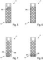
- Fresh water is applied with a relatively small dosage of cleaning agent or with a relatively low surfactant content, which means that it has a lower surface tension than the fresh water, but still a relatively high surface tension, and can then be used for a time of about 3 seconds when the carrier 11 is tilted drain, so a relatively small wet area 28b remains.
- This extends upwards from the lower end area 14 and is somewhat narrower there due to the respective arrangement of the hydrophilic areas 18.
- the liquid therefore naturally begins to flow from top to bottom and to drain off at the bottom in accordance with the effect of the force. It would be similar with airflow or rotation of the carrier as previously described.
- fresh water is applied with a medium dosage of cleaning agent or with a medium surfactant content, which means that it has a mean surface tension that is lower than that of 4 .
- a medium dosage of cleaning agent or with a medium surfactant content which means that it has a mean surface tension that is lower than that of 4 .
- some liquid has drained from the carrier 11, so that a relatively large moist area 28c remains in the measuring area 15. This extends from the lower end area 14 almost to the top and is also something there again narrower.
- the capacitive coupling between the electrodes 20a and 20b compared to 3 significantly increased, which in turn was recorded by capacitive measurement. If the measurement duration were increased from 3 seconds to 5 seconds or even 10 seconds, for example, then a little more liquid would run off, but then the distinguishability would be reduced 3 difficult, since there would possibly be hardly any liquid left.
- the 9 shows an embodiment of a carrier 111 with a significantly higher number of hydrophobic areas 117 and hydrophilic areas 118 in a measurement area 115. They are again arranged in a pattern as before, but twice the number next to each other and one below the other. Thus four times as many areas 117 and 118 are provided.
- connection contacts 125a and 125b are provided on the carrier surface 113 of the carrier substrate 112, to which electrodes, not shown, are attached as in FIG 2 are led. Due to the smaller training of the respective areas 117 and 118 may be a better differentiation of the different surfactant contents, because the amount of liquid remaining in each case may be different.
- the structure of such a device 31 is shown as described above.
- the carrier 11 is held on a short tubular holder 33 which is open at the front towards an interior space 34 and which is closed at the rear. It runs at an angle ⁇ to the dashed central longitudinal axis of the holder 33, which corresponds to the horizontal, which is approximately 55° here.
- This angle ⁇ determines the strength or effect of gravity on the liquid that is on the surface of the carrier 11, i.e. in the measuring area 15.
- a dishwasher 40 In the 12 the structure of a dishwasher 40 according to the invention is shown as a water-bearing household appliance which has a washing chamber 41 as a treatment chamber in which dishes are cleaned. Water is sucked off by a pump 43 from a sump 42 below and pumped through a line 44 into a spray arm 45 . From there, the water is sprayed onto the dishes as rinsing water 47 in corresponding small jets into the rinsing chamber 41 . The water then also splashes onto the device 31 on the right in the side wall with the carrier 11 or onto its measuring area 15. A round hole can be made very easily in the side wall for the round holder 33, in which it is then sealed and attached.
- the carrier 11 is electrically contacted with its connecting contacts 25 and a connecting line 26 and connected to a controller 48 of the dishwasher 40 .
- the controller 48 can then use the aforementioned method to determine how much cleaning agent or tenside is contained in the rinsing water 47 . In this way, a better and possibly more economical dosing can take place, in any case the dosing can be precisely adjusted. So it can be stopped or increased as needed.
- a temperature of the liquid can also be detected or its temperature can be taken into account. This can be done passively using a corresponding temperature sensor, which is either attached to the support 11 or somewhere on the dishwasher or its water supply, for example on the pump 43 or a heater for the water.
- a corresponding temperature sensor which is either attached to the support 11 or somewhere on the dishwasher or its water supply, for example on the pump 43 or a heater for the water.
- the corresponding relationship between temperature and flow behavior has been explained before. It can be calculated out, so to speak, or by heating the carrier 11 appropriately, it can be as constant as possible Temperature for the measurement processes are reached. In this way, an influence of the temperature or a falsification of the measurement process can be reduced as far as possible or avoided entirely.
- the surface tension in the rinsing water 47 can then be determined in the controller 48 by calculation or by comparison with stored values, and then from this its surfactant content.
- the controller 48 can use this to better adjust the dosage of cleaning agent into the rinsing water 47 .
Landscapes
- Chemical & Material Sciences (AREA)
- Immunology (AREA)
- Physics & Mathematics (AREA)
- Health & Medical Sciences (AREA)
- Analytical Chemistry (AREA)
- Biochemistry (AREA)
- General Health & Medical Sciences (AREA)
- Life Sciences & Earth Sciences (AREA)
- Pathology (AREA)
- General Physics & Mathematics (AREA)
- Chemical Kinetics & Catalysis (AREA)
- Electrochemistry (AREA)
- Engineering & Computer Science (AREA)
- Textile Engineering (AREA)
- Investigating Or Analyzing Materials By The Use Of Electric Means (AREA)
- Washing And Drying Of Tableware (AREA)
Claims (15)
- Procédé pour tester un liquide (47) dans un appareil domestique (40) conduisant l'eau, dans lequel une tension de surface d'un liquide (47) doit être détectée, comprenant les étapes consistant à:- fournir un support (11) plat et plan, dans lequel :- ledit support (11) a une surface de support plate et plane (13, 113),- des régions hydrophobes (17, 117) et des régions hydrophiles (18, 118) alternées sont prévues sur la surface de support (13, 113),- appliquer le liquide (47) à tester sur la surface de support (13, 113),- ensuite, soumettre le liquide (47) sur la surface de support (13, 113) à une force telle et adaptée pour enlever au moins partiellement le liquide (47) de la surface de support (13, 113),- la quantité de liquide (28) restant éventuellement sur la surface de support (13, 113) est détectée et utilisée comme une mesure de la tension superficielle du liquide (47) en cours d'examen, la tension superficielle du liquide étant plus grande plus la quantité de liquide (28) restant sur la surface de support (13, 113) est réduite.
- Procédé selon la revendication 1, caractérisé en ce que les régions hydrophobes (17, 117) et les régions hydrophiles (18, 118) forment un motif régulier dans une direction sur la surface du support (13, 113), en particulier dans laquelle direction les régions hydrophobes (17, 117) et les régions hydrophiles (18, 118) sont de taille égale, de préférence, les régions hydrophobes (17, 117) et les régions hydrophiles (18, 118) forment un motif régulier également dans une deuxième direction perpendiculaire à l'autre direction, en particulier dans chacune des deux directions, au moins trois changements étant prévus entre une région hydrophobe (17, 117) et une région hydrophile (18, 118).
- Procédé selon la revendication 1 ou 2, caractérisé en ce que toutes les régions hydrophobes (17, 117) et/ou toutes les régions hydrophiles (18, 118) ont la même taille, de préférence toutes les régions hydrophobes (17, 117) et/ou toutes les régions hydrophiles (18, 118) sont identiques, les régions hydrophobes (17, 117) et les régions hydrophiles (18, 118) étant de préférence rectangulaires, les régions hydrophobes (17, 117) et les régions hydrophiles (18, 118) étant de préférence en contact direct les unes avec les autres dans les coins.
- Procédé selon l'une quelconque des revendications précédentes, caractérisé en ce que la force a une direction ou est une force directionnelle, respectivement, dans lequel de préférence le long de la direction de la force, plus de régions hydrophobes (17, 117) et de régions hydrophiles (18, 118) sont prévues que dans une direction perpendiculaire à celle-ci, de préférence deux fois plus à dix fois plus, dans lequel en particulier la surface de support (13, 113) est plus longue dans la direction le long de la force que dans la direction perpendiculaire à celle-ci, de préférence deux fois à dix fois plus longue.
- Procédé selon la revendication 4, caractérisé en ce que les régions hydrophobes (17, 117) et/ou les régions hydrophiles (18, 118) ont la même extension dans la direction de la force ou du mouvement du liquide (47) pendant l'enlèvement que dans une direction perpendiculaire à celle-ci.
- Procédé selon l'une quelconque des revendications précédentes, caractérisé en ce que la surface de support (13, 113) ne présente essentiellement, en particulier complètement à l'exception d'une zone de raccordement, que des régions hydrophobes (17, 117) et des régions hydrophiles (18, 118) qui sont disposées en alternance.
- Procédé selon l'une quelconque des revendications précédentes, caractérisé en ce que la force est un écoulement d'air ou la gravité, dans lequel, de préférence avec la gravité comme force, le support (11) avec la surface de support (13, 113) est incliné selon un angle (α) compris entre 10° et 80° par rapport à l'horizontale.
- Procédé selon l'une quelconque des revendications précédentes, caractérisé en ce que la quantité restante de liquide (28) sur la surface de support (13, 113) est détectée après un certain temps, de préférence entre 2 sec et 20 sec après l'application du liquide (47) ou après le début de la suspension de l'application de la force, en particulier entre 5 sec et 10 sec ensuite.
- Procédé selon l'une quelconque des revendications précédentes, caractérisé en ce que la quantité de liquide (28) restant sur la surface du support (13, 113) est détectée de manière capacitive, de préférence par des électrodes électriquement conductrices (20) fixées sur le support (11) avec une mesure de la capacité ou du couplage capacitif entre les deux électrodes, les deux électrodes (20) étant disposées de telle sorte que la capacité ou le couplage capacitif entre les deux électrodes dépende de la quantité de liquide (28) sur la surface du support (13, 113) ou ait une relation prédéterminée avec celle-ci, en particulier les électrodes (20) étant disposées de telle sorte que la capacité ou le couplage capacitif entre les deux électrodes dépende de la quantité de liquide (28) sur la surface du support (13, 113) ou ait une relation prédéterminée avec celle-ci. le couplage capacitif entre les deux électrodes dépend de la quantité de liquide (28) sur la surface de support (13, 113) ou est en relation prédéterminée avec celle-ci, dans lequel en particulier les électrodes (20) sont en forme de doigts (23) et s'étendent d'un côté longitudinal à l'opposé de sorte qu'elles sont emboîtées l'une dans l'autre.
- Procédé selon l'une quelconque des revendications 1 à 8, caractérisé en ce que la quantité de liquide (28) restant sur la surface du support est détectée optiquement, de préférence au moyen d'une mesure de transmission, d'une mesure de réfraction ou d'une mesure de réflexion.
- Procédé selon l'une quelconque des revendications précédentes, caractérisé en ce que le support (11) peut être chauffé, de préférence au moyen d'un dispositif de chauffage fixé sur le côté du support (11) opposé à la surface du support (13, 113), la tension superficielle du liquide (47) étant déterminée en fonction de certaines températures différentes.
- Procédé selon l'une quelconque des revendications précédentes, caractérisé en ce qu'une température du support (11) et/ou du liquide (28) sur le support (11) est déterminée pour la détection en fonction de la température de la tension superficielle du liquide (47), un capteur de température étant de préférence appliqué directement sur le support (11), en particulier entre les régions hydrophobes (17, 117) et les régions hydrophiles (18, 118).
- Procédé selon l'une quelconque des revendications précédentes, caractérisé en ce que les régions hydrophobes (17, 117) et les régions hydrophiles (18, 118) se distinguent par le matériau de leur surface, les régions hydrophobes (17, 117) présentant de préférence un revêtement choisi dans le groupe constitué par le parylène, le PTFE ou un nano-revêtement à effet lotus, en particulier la surface des régions hydrophobes (17, 117) étant formée par dépôt de vapeur de plastique ou par un revêtement DLC.
- Procédé selon l'une quelconque des revendications 1 à 12, caractérisé en ce que les régions hydrophobes (17, 117) et les régions hydrophiles (18, 118) se distinguent les unes des autres par une structure de surface, les régions hydrophiles (18, 118) présentant de préférence une rugosité de surface supérieure à celle des régions hydrophobes (17, 117), 117), où en particulier une rugosité de surface différente entre les régions hydrophobes (17, 117) et les régions hydrophiles (18, 118) est produite par une structuration partielle de la surface, de préférence choisie dans le groupe sérigraphie, sablage partiel, sablage masqué, gravure masquée ou laser.
- Appareil domestique (40) conduisant l'eau pour la mise en oeuvre du procédé selon l'une quelconque des revendications précédentes, caractérisé en ce que:- l'appareil domestique (40) transportant de l'eau présente un support (11) avec une surface de support plate et plane (13, 113) qui présente des régions hydrophobes (17, 117) et des régions hydrophiles (18, 118),- des régions hydrophobes (17, 117) et des régions hydrophiles (18, 118) alternées sont prévues sur la surface de support (13, 113),- des moyens (45) sont prévus pour appliquer un liquide (47) à tester sur la surface de support (13, 113),- des moyens de détection (48) sont prévus pour détecter si et, le cas échéant, quelle quantité de liquide (47) reste sur la surface de support (13, 113).
Applications Claiming Priority (1)
| Application Number | Priority Date | Filing Date | Title |
|---|---|---|---|
| DE102019207080.9A DE102019207080B4 (de) | 2019-05-15 | 2019-05-15 | Verfahren zur Untersuchung einer Flüssigkeit und wasserführendes Haushaltsgerät |
Publications (2)
| Publication Number | Publication Date |
|---|---|
| EP3738497A1 EP3738497A1 (fr) | 2020-11-18 |
| EP3738497B1 true EP3738497B1 (fr) | 2023-03-22 |
Family
ID=70189827
Family Applications (1)
| Application Number | Title | Priority Date | Filing Date |
|---|---|---|---|
| EP20168157.4A Active EP3738497B1 (fr) | 2019-05-15 | 2020-04-06 | Procédé d'examen d'un appareil électroménager d'acheminement de liquide et d'eau |
Country Status (3)
| Country | Link |
|---|---|
| EP (1) | EP3738497B1 (fr) |
| KR (1) | KR20200132732A (fr) |
| DE (1) | DE102019207080B4 (fr) |
Families Citing this family (1)
| Publication number | Priority date | Publication date | Assignee | Title |
|---|---|---|---|---|
| CN114295521B (zh) * | 2022-01-07 | 2023-04-25 | 四川大学 | 使用针管测量液体表面张力系数的方法 |
Citations (1)
| Publication number | Priority date | Publication date | Assignee | Title |
|---|---|---|---|---|
| EP1350575A2 (fr) * | 2002-02-14 | 2003-10-08 | Institut für Polymerforschung Dresden e.V. | Surface avec ultrahydrophobie commutable, et procédé de fabrication associé |
Family Cites Families (9)
| Publication number | Priority date | Publication date | Assignee | Title |
|---|---|---|---|---|
| DE3303940A1 (de) * | 1983-02-05 | 1984-08-09 | Licentia Patent-Verwaltungs-Gmbh, 6000 Frankfurt | Verfahren und anordnung zur messung der oberflaechenspannung von fluessigkeiten |
| DE19529787B4 (de) * | 1995-08-12 | 2011-05-19 | E.G.O. Elektro-Gerätebau GmbH | Verfahren und Einrichtung zur füllstandsunabhängigen Messung der Oberflächenspannung flüssiger Substanzen |
| DE10308198B3 (de) * | 2003-02-25 | 2004-07-22 | Miele & Cie. Kg | Verfahren und System zur Bestimmung der Oberflächenspannung nach der Blasendruckmethode |
| DE102005007870B4 (de) * | 2005-02-21 | 2007-12-06 | E.G.O. Elektro-Gerätebau GmbH | Verfahren und Vorrichtung zum Messen der Oberflächenspannung von Flüssigkeiten |
| DE102006025622A1 (de) * | 2006-05-24 | 2007-11-29 | E.G.O. Elektro-Gerätebau GmbH | Sensoreinrichtung zur Leitfähigkeitsmessung und Verfahren zu ihrem Betrieb |
| DE102006060256A1 (de) * | 2006-12-14 | 2008-06-26 | E.G.O. Elektro-Gerätebau GmbH | Verfahren zur Steuerung einer Waschmaschine |
| DE102008040334B4 (de) * | 2008-07-10 | 2011-03-17 | BSH Bosch und Siemens Hausgeräte GmbH | Verfahren zum Betreiben einer Geschirrspülmaschine, Überwachungseinrichtung für eine Spülflotte und Geschirrspülmaschine |
| PL2319382T3 (pl) * | 2010-10-14 | 2014-11-28 | V Zug Ag | Zmywarka do naczyń albo pralka z urządzeniem pomiarowym do mierzenia napięcia powierzchniowego ługu piorącego |
| DE102018209973A1 (de) * | 2018-06-20 | 2019-12-24 | BSH Hausgeräte GmbH | Geschirrspülmaschine, Verfahren zum Betreiben einer Geschirrspülmaschine und Computerprogrammprodukt |
-
2019
- 2019-05-15 DE DE102019207080.9A patent/DE102019207080B4/de not_active Expired - Fee Related
-
2020
- 2020-04-06 EP EP20168157.4A patent/EP3738497B1/fr active Active
- 2020-05-13 KR KR1020200057305A patent/KR20200132732A/ko active Pending
Patent Citations (1)
| Publication number | Priority date | Publication date | Assignee | Title |
|---|---|---|---|---|
| EP1350575A2 (fr) * | 2002-02-14 | 2003-10-08 | Institut für Polymerforschung Dresden e.V. | Surface avec ultrahydrophobie commutable, et procédé de fabrication associé |
Also Published As
| Publication number | Publication date |
|---|---|
| KR20200132732A (ko) | 2020-11-25 |
| EP3738497A1 (fr) | 2020-11-18 |
| DE102019207080A1 (de) | 2020-11-19 |
| DE102019207080B4 (de) | 2021-04-01 |
Similar Documents
| Publication | Publication Date | Title |
|---|---|---|
| EP2215301B1 (fr) | Procédé pour faire fonctionner un lave-linge avec un dispositif de chauffage | |
| EP3117036B1 (fr) | Sèche-linge équipé d'un dispositif de rinçage et d'un dispositif de dépôt de peluches ainsi que procédé pour le faire fonctionner | |
| DE19806559B4 (de) | Verfahren und Vorrichtung zur Behandlung von Geschirr in Spülmaschinen | |
| DE60223265T2 (de) | Geschirrspülmaschine mit Flachfiltereinrichtung umfassend Bereiche mit unterschiedlichen Lochdimensionen | |
| DE102010039602A1 (de) | Flusenfilter für ein Wäschebehandlungsgerät, Wäschebehandlungsgerät mit Aufnahmeraum für den Flusenfilter und Filtereinsatz | |
| EP2794975B1 (fr) | Élément d'un appareil ménager pourvu d'un revêtement | |
| EP3738497B1 (fr) | Procédé d'examen d'un appareil électroménager d'acheminement de liquide et d'eau | |
| EP3369476A1 (fr) | Dispositif et procédé de fourniture d'un fluide de nettoyage | |
| DE19934090A1 (de) | Spülwannensystem | |
| EP1481235B1 (fr) | Appareil a circulation d'eau avec un dispositif pour controler la formation d'un depot | |
| EP2319382B1 (fr) | Lave-vaisselle ou lave-linge doté d'un dispositif de mesure pour mesurer la tension de surface de la lessive | |
| DE3201129C2 (fr) | ||
| EP4120876B1 (fr) | Appareil de cuisson domestique à pef | |
| DE19929615C1 (de) | Vorrichtung und Verwendung der Vorrichtung zur Überwachung von absichtlichen oder unvermeidbaren Schichtabscheidungen | |
| WO2015106948A1 (fr) | Dispositif et un procédé de nettoyage d'un composant disposé dans un circuit d'air de traitement d'un séchoir et séchoir équipé d'un tel dispositif | |
| DE102008040334B4 (de) | Verfahren zum Betreiben einer Geschirrspülmaschine, Überwachungseinrichtung für eine Spülflotte und Geschirrspülmaschine | |
| DE102019207081B4 (de) | Verfahren zur Untersuchung einer Flüssigkeit und wasserführendes Haushaltsgerät | |
| DE102020000316A1 (de) | Trübungssensor sowie hiermit ausgerüstetes wasserführendes Haushaltsgerät | |
| DE1503792A1 (de) | Spruehvorrichtung fuer automatische Geschirrspuelmaschinen | |
| EP3816335B1 (fr) | Dispositif capteur, procédé de fonctionnement d'un tel dispositif capteur et appareil électroménager à circulation d'eau | |
| EP1776032A1 (fr) | Procede pour ajouter des agents mouillants dans un lave-vaisselle commande par programme | |
| EP2422678B1 (fr) | Appareil ménager transportant de l'eau doté d'un dispositif de mesure de la tension de surface lavable | |
| DE102020117844A1 (de) | Reinigungschemiebausystem und Gargerät | |
| EP1523674B1 (fr) | Procede de production d'un substrat hydrophile pourvu d'une electrode en couche | |
| DE212015000096U1 (de) | Quetschventil und automatische Analysevorrichtung mit einem Quetschventil |
Legal Events
| Date | Code | Title | Description |
|---|---|---|---|
| PUAI | Public reference made under article 153(3) epc to a published international application that has entered the european phase |
Free format text: ORIGINAL CODE: 0009012 |
|
| STAA | Information on the status of an ep patent application or granted ep patent |
Free format text: STATUS: THE APPLICATION HAS BEEN PUBLISHED |
|
| AK | Designated contracting states |
Kind code of ref document: A1 Designated state(s): AL AT BE BG CH CY CZ DE DK EE ES FI FR GB GR HR HU IE IS IT LI LT LU LV MC MK MT NL NO PL PT RO RS SE SI SK SM TR |
|
| AX | Request for extension of the european patent |
Extension state: BA ME |
|
| STAA | Information on the status of an ep patent application or granted ep patent |
Free format text: STATUS: REQUEST FOR EXAMINATION WAS MADE |
|
| 17P | Request for examination filed |
Effective date: 20210311 |
|
| RBV | Designated contracting states (corrected) |
Designated state(s): AL AT BE BG CH CY CZ DE DK EE ES FI FR GB GR HR HU IE IS IT LI LT LU LV MC MK MT NL NO PL PT RO RS SE SI SK SM TR |
|
| GRAP | Despatch of communication of intention to grant a patent |
Free format text: ORIGINAL CODE: EPIDOSNIGR1 |
|
| STAA | Information on the status of an ep patent application or granted ep patent |
Free format text: STATUS: GRANT OF PATENT IS INTENDED |
|
| INTG | Intention to grant announced |
Effective date: 20221031 |
|
| GRAS | Grant fee paid |
Free format text: ORIGINAL CODE: EPIDOSNIGR3 |
|
| GRAA | (expected) grant |
Free format text: ORIGINAL CODE: 0009210 |
|
| STAA | Information on the status of an ep patent application or granted ep patent |
Free format text: STATUS: THE PATENT HAS BEEN GRANTED |
|
| AK | Designated contracting states |
Kind code of ref document: B1 Designated state(s): AL AT BE BG CH CY CZ DE DK EE ES FI FR GB GR HR HU IE IS IT LI LT LU LV MC MK MT NL NO PL PT RO RS SE SI SK SM TR |
|
| REG | Reference to a national code |
Ref country code: GB Ref legal event code: FG4D Free format text: NOT ENGLISH |
|
| REG | Reference to a national code |
Ref country code: CH Ref legal event code: EP |
|
| REG | Reference to a national code |
Ref country code: DE Ref legal event code: R096 Ref document number: 502020002779 Country of ref document: DE |
|
| REG | Reference to a national code |
Ref country code: IE Ref legal event code: FG4D Free format text: LANGUAGE OF EP DOCUMENT: GERMAN |
|
| REG | Reference to a national code |
Ref country code: AT Ref legal event code: REF Ref document number: 1554787 Country of ref document: AT Kind code of ref document: T Effective date: 20230415 |
|
| REG | Reference to a national code |
Ref country code: LT Ref legal event code: MG9D |
|
| REG | Reference to a national code |
Ref country code: NL Ref legal event code: MP Effective date: 20230322 |
|
| PG25 | Lapsed in a contracting state [announced via postgrant information from national office to epo] |
Ref country code: RS Free format text: LAPSE BECAUSE OF FAILURE TO SUBMIT A TRANSLATION OF THE DESCRIPTION OR TO PAY THE FEE WITHIN THE PRESCRIBED TIME-LIMIT Effective date: 20230322 Ref country code: NO Free format text: LAPSE BECAUSE OF FAILURE TO SUBMIT A TRANSLATION OF THE DESCRIPTION OR TO PAY THE FEE WITHIN THE PRESCRIBED TIME-LIMIT Effective date: 20230622 Ref country code: LV Free format text: LAPSE BECAUSE OF FAILURE TO SUBMIT A TRANSLATION OF THE DESCRIPTION OR TO PAY THE FEE WITHIN THE PRESCRIBED TIME-LIMIT Effective date: 20230322 Ref country code: LT Free format text: LAPSE BECAUSE OF FAILURE TO SUBMIT A TRANSLATION OF THE DESCRIPTION OR TO PAY THE FEE WITHIN THE PRESCRIBED TIME-LIMIT Effective date: 20230322 Ref country code: HR Free format text: LAPSE BECAUSE OF FAILURE TO SUBMIT A TRANSLATION OF THE DESCRIPTION OR TO PAY THE FEE WITHIN THE PRESCRIBED TIME-LIMIT Effective date: 20230322 |
|
| PG25 | Lapsed in a contracting state [announced via postgrant information from national office to epo] |
Ref country code: SE Free format text: LAPSE BECAUSE OF FAILURE TO SUBMIT A TRANSLATION OF THE DESCRIPTION OR TO PAY THE FEE WITHIN THE PRESCRIBED TIME-LIMIT Effective date: 20230322 Ref country code: NL Free format text: LAPSE BECAUSE OF FAILURE TO SUBMIT A TRANSLATION OF THE DESCRIPTION OR TO PAY THE FEE WITHIN THE PRESCRIBED TIME-LIMIT Effective date: 20230322 Ref country code: GR Free format text: LAPSE BECAUSE OF FAILURE TO SUBMIT A TRANSLATION OF THE DESCRIPTION OR TO PAY THE FEE WITHIN THE PRESCRIBED TIME-LIMIT Effective date: 20230623 Ref country code: FI Free format text: LAPSE BECAUSE OF FAILURE TO SUBMIT A TRANSLATION OF THE DESCRIPTION OR TO PAY THE FEE WITHIN THE PRESCRIBED TIME-LIMIT Effective date: 20230322 |
|
| PG25 | Lapsed in a contracting state [announced via postgrant information from national office to epo] |
Ref country code: SM Free format text: LAPSE BECAUSE OF FAILURE TO SUBMIT A TRANSLATION OF THE DESCRIPTION OR TO PAY THE FEE WITHIN THE PRESCRIBED TIME-LIMIT Effective date: 20230322 Ref country code: RO Free format text: LAPSE BECAUSE OF FAILURE TO SUBMIT A TRANSLATION OF THE DESCRIPTION OR TO PAY THE FEE WITHIN THE PRESCRIBED TIME-LIMIT Effective date: 20230322 Ref country code: PT Free format text: LAPSE BECAUSE OF FAILURE TO SUBMIT A TRANSLATION OF THE DESCRIPTION OR TO PAY THE FEE WITHIN THE PRESCRIBED TIME-LIMIT Effective date: 20230724 Ref country code: ES Free format text: LAPSE BECAUSE OF FAILURE TO SUBMIT A TRANSLATION OF THE DESCRIPTION OR TO PAY THE FEE WITHIN THE PRESCRIBED TIME-LIMIT Effective date: 20230322 Ref country code: EE Free format text: LAPSE BECAUSE OF FAILURE TO SUBMIT A TRANSLATION OF THE DESCRIPTION OR TO PAY THE FEE WITHIN THE PRESCRIBED TIME-LIMIT Effective date: 20230322 |
|
| PG25 | Lapsed in a contracting state [announced via postgrant information from national office to epo] |
Ref country code: SK Free format text: LAPSE BECAUSE OF FAILURE TO SUBMIT A TRANSLATION OF THE DESCRIPTION OR TO PAY THE FEE WITHIN THE PRESCRIBED TIME-LIMIT Effective date: 20230322 Ref country code: PL Free format text: LAPSE BECAUSE OF FAILURE TO SUBMIT A TRANSLATION OF THE DESCRIPTION OR TO PAY THE FEE WITHIN THE PRESCRIBED TIME-LIMIT Effective date: 20230322 Ref country code: IS Free format text: LAPSE BECAUSE OF FAILURE TO SUBMIT A TRANSLATION OF THE DESCRIPTION OR TO PAY THE FEE WITHIN THE PRESCRIBED TIME-LIMIT Effective date: 20230722 |
|
| REG | Reference to a national code |
Ref country code: CH Ref legal event code: PL |
|
| PG25 | Lapsed in a contracting state [announced via postgrant information from national office to epo] |
Ref country code: LU Free format text: LAPSE BECAUSE OF NON-PAYMENT OF DUE FEES Effective date: 20230406 |
|
| REG | Reference to a national code |
Ref country code: DE Ref legal event code: R097 Ref document number: 502020002779 Country of ref document: DE |
|
| REG | Reference to a national code |
Ref country code: BE Ref legal event code: MM Effective date: 20230430 |
|
| PG25 | Lapsed in a contracting state [announced via postgrant information from national office to epo] |
Ref country code: MC Free format text: LAPSE BECAUSE OF FAILURE TO SUBMIT A TRANSLATION OF THE DESCRIPTION OR TO PAY THE FEE WITHIN THE PRESCRIBED TIME-LIMIT Effective date: 20230322 |
|
| PLBE | No opposition filed within time limit |
Free format text: ORIGINAL CODE: 0009261 |
|
| STAA | Information on the status of an ep patent application or granted ep patent |
Free format text: STATUS: NO OPPOSITION FILED WITHIN TIME LIMIT |
|
| PG25 | Lapsed in a contracting state [announced via postgrant information from national office to epo] |
Ref country code: SI Free format text: LAPSE BECAUSE OF FAILURE TO SUBMIT A TRANSLATION OF THE DESCRIPTION OR TO PAY THE FEE WITHIN THE PRESCRIBED TIME-LIMIT Effective date: 20230322 Ref country code: MC Free format text: LAPSE BECAUSE OF FAILURE TO SUBMIT A TRANSLATION OF THE DESCRIPTION OR TO PAY THE FEE WITHIN THE PRESCRIBED TIME-LIMIT Effective date: 20230322 Ref country code: LI Free format text: LAPSE BECAUSE OF NON-PAYMENT OF DUE FEES Effective date: 20230430 Ref country code: DK Free format text: LAPSE BECAUSE OF FAILURE TO SUBMIT A TRANSLATION OF THE DESCRIPTION OR TO PAY THE FEE WITHIN THE PRESCRIBED TIME-LIMIT Effective date: 20230322 Ref country code: CZ Free format text: LAPSE BECAUSE OF FAILURE TO SUBMIT A TRANSLATION OF THE DESCRIPTION OR TO PAY THE FEE WITHIN THE PRESCRIBED TIME-LIMIT Effective date: 20230322 Ref country code: CH Free format text: LAPSE BECAUSE OF NON-PAYMENT OF DUE FEES Effective date: 20230430 |
|
| REG | Reference to a national code |
Ref country code: IE Ref legal event code: MM4A |
|
| 26N | No opposition filed |
Effective date: 20240102 |
|
| PG25 | Lapsed in a contracting state [announced via postgrant information from national office to epo] |
Ref country code: BE Free format text: LAPSE BECAUSE OF NON-PAYMENT OF DUE FEES Effective date: 20230430 |
|
| PG25 | Lapsed in a contracting state [announced via postgrant information from national office to epo] |
Ref country code: IE Free format text: LAPSE BECAUSE OF NON-PAYMENT OF DUE FEES Effective date: 20230406 |
|
| PG25 | Lapsed in a contracting state [announced via postgrant information from national office to epo] |
Ref country code: IE Free format text: LAPSE BECAUSE OF NON-PAYMENT OF DUE FEES Effective date: 20230406 |
|
| PG25 | Lapsed in a contracting state [announced via postgrant information from national office to epo] |
Ref country code: IT Free format text: LAPSE BECAUSE OF FAILURE TO SUBMIT A TRANSLATION OF THE DESCRIPTION OR TO PAY THE FEE WITHIN THE PRESCRIBED TIME-LIMIT Effective date: 20230322 Ref country code: FR Free format text: LAPSE BECAUSE OF NON-PAYMENT OF DUE FEES Effective date: 20230522 |
|
| PGFP | Annual fee paid to national office [announced via postgrant information from national office to epo] |
Ref country code: DE Payment date: 20240424 Year of fee payment: 5 |
|
| PG25 | Lapsed in a contracting state [announced via postgrant information from national office to epo] |
Ref country code: BG Free format text: LAPSE BECAUSE OF FAILURE TO SUBMIT A TRANSLATION OF THE DESCRIPTION OR TO PAY THE FEE WITHIN THE PRESCRIBED TIME-LIMIT Effective date: 20230322 |
|
| PG25 | Lapsed in a contracting state [announced via postgrant information from national office to epo] |
Ref country code: BG Free format text: LAPSE BECAUSE OF FAILURE TO SUBMIT A TRANSLATION OF THE DESCRIPTION OR TO PAY THE FEE WITHIN THE PRESCRIBED TIME-LIMIT Effective date: 20230322 |
|
| GBPC | Gb: european patent ceased through non-payment of renewal fee |
Effective date: 20240406 |
|
| PG25 | Lapsed in a contracting state [announced via postgrant information from national office to epo] |
Ref country code: GB Free format text: LAPSE BECAUSE OF NON-PAYMENT OF DUE FEES Effective date: 20240406 |
|
| PG25 | Lapsed in a contracting state [announced via postgrant information from national office to epo] |
Ref country code: GB Free format text: LAPSE BECAUSE OF NON-PAYMENT OF DUE FEES Effective date: 20240406 |
|
| PGFP | Annual fee paid to national office [announced via postgrant information from national office to epo] |
Ref country code: AT Payment date: 20250721 Year of fee payment: 5 |
|
| PG25 | Lapsed in a contracting state [announced via postgrant information from national office to epo] |
Ref country code: CY Free format text: LAPSE BECAUSE OF FAILURE TO SUBMIT A TRANSLATION OF THE DESCRIPTION OR TO PAY THE FEE WITHIN THE PRESCRIBED TIME-LIMIT; INVALID AB INITIO Effective date: 20200406 |
|
| PG25 | Lapsed in a contracting state [announced via postgrant information from national office to epo] |
Ref country code: HU Free format text: LAPSE BECAUSE OF FAILURE TO SUBMIT A TRANSLATION OF THE DESCRIPTION OR TO PAY THE FEE WITHIN THE PRESCRIBED TIME-LIMIT; INVALID AB INITIO Effective date: 20200406 |
|
| REG | Reference to a national code |
Ref country code: DE Ref legal event code: R119 Ref document number: 502020002779 Country of ref document: DE |
|
| PG25 | Lapsed in a contracting state [announced via postgrant information from national office to epo] |
Ref country code: TR Free format text: LAPSE BECAUSE OF FAILURE TO SUBMIT A TRANSLATION OF THE DESCRIPTION OR TO PAY THE FEE WITHIN THE PRESCRIBED TIME-LIMIT Effective date: 20230322 |
|
| PG25 | Lapsed in a contracting state [announced via postgrant information from national office to epo] |
Ref country code: DE Free format text: LAPSE BECAUSE OF NON-PAYMENT OF DUE FEES Effective date: 20251104 |