EP3738526B1 - Agrafeuse chirurgicale avec indicateur d'état d'enclume - Google Patents
Agrafeuse chirurgicale avec indicateur d'état d'enclume Download PDFInfo
- Publication number
- EP3738526B1 EP3738526B1 EP20156669.2A EP20156669A EP3738526B1 EP 3738526 B1 EP3738526 B1 EP 3738526B1 EP 20156669 A EP20156669 A EP 20156669A EP 3738526 B1 EP3738526 B1 EP 3738526B1
- Authority
- EP
- European Patent Office
- Prior art keywords
- indicator
- anvil
- stapling head
- assembly
- head assembly
- Prior art date
- Legal status (The legal status is an assumption and is not a legal conclusion. Google has not performed a legal analysis and makes no representation as to the accuracy of the status listed.)
- Active
Links
Images
















Classifications
-
- A—HUMAN NECESSITIES
- A61—MEDICAL OR VETERINARY SCIENCE; HYGIENE
- A61B—DIAGNOSIS; SURGERY; IDENTIFICATION
- A61B17/00—Surgical instruments, devices or methods
- A61B17/068—Surgical staplers, e.g. containing multiple staples or clamps
-
- A—HUMAN NECESSITIES
- A61—MEDICAL OR VETERINARY SCIENCE; HYGIENE
- A61B—DIAGNOSIS; SURGERY; IDENTIFICATION
- A61B17/00—Surgical instruments, devices or methods
- A61B17/11—Surgical instruments, devices or methods for performing anastomosis; Buttons for anastomosis
- A61B17/115—Staplers for performing anastomosis, e.g. in a single operation
- A61B17/1155—Circular staplers comprising a plurality of staples
-
- A—HUMAN NECESSITIES
- A61—MEDICAL OR VETERINARY SCIENCE; HYGIENE
- A61B—DIAGNOSIS; SURGERY; IDENTIFICATION
- A61B17/00—Surgical instruments, devices or methods
- A61B2017/00017—Electrical control of surgical instruments
-
- A—HUMAN NECESSITIES
- A61—MEDICAL OR VETERINARY SCIENCE; HYGIENE
- A61B—DIAGNOSIS; SURGERY; IDENTIFICATION
- A61B17/00—Surgical instruments, devices or methods
- A61B2017/00367—Details of actuation of instruments, e.g. relations between pushing buttons, or the like, and activation of the tool, working tip, or the like
- A61B2017/00398—Details of actuation of instruments, e.g. relations between pushing buttons, or the like, and activation of the tool, working tip, or the like using powered actuators, e.g. stepper motors, solenoids
-
- A—HUMAN NECESSITIES
- A61—MEDICAL OR VETERINARY SCIENCE; HYGIENE
- A61B—DIAGNOSIS; SURGERY; IDENTIFICATION
- A61B17/00—Surgical instruments, devices or methods
- A61B17/28—Surgical forceps
- A61B17/29—Forceps for use in minimally invasive surgery
- A61B2017/2926—Details of heads or jaws
- A61B2017/2932—Transmission of forces to jaw members
- A61B2017/2943—Toothed members, e.g. rack and pinion
-
- A—HUMAN NECESSITIES
- A61—MEDICAL OR VETERINARY SCIENCE; HYGIENE
- A61B—DIAGNOSIS; SURGERY; IDENTIFICATION
- A61B90/00—Instruments, implements or accessories specially adapted for surgery or diagnosis and not covered by any of the groups A61B1/00 - A61B50/00, e.g. for luxation treatment or for protecting wound edges
- A61B90/06—Measuring instruments not otherwise provided for
- A61B2090/061—Measuring instruments not otherwise provided for for measuring dimensions, e.g. length
-
- A—HUMAN NECESSITIES
- A61—MEDICAL OR VETERINARY SCIENCE; HYGIENE
- A61B—DIAGNOSIS; SURGERY; IDENTIFICATION
- A61B90/00—Instruments, implements or accessories specially adapted for surgery or diagnosis and not covered by any of the groups A61B1/00 - A61B50/00, e.g. for luxation treatment or for protecting wound edges
- A61B90/06—Measuring instruments not otherwise provided for
- A61B2090/062—Measuring instruments not otherwise provided for penetration depth
-
- A—HUMAN NECESSITIES
- A61—MEDICAL OR VETERINARY SCIENCE; HYGIENE
- A61B—DIAGNOSIS; SURGERY; IDENTIFICATION
- A61B90/00—Instruments, implements or accessories specially adapted for surgery or diagnosis and not covered by any of the groups A61B1/00 - A61B50/00, e.g. for luxation treatment or for protecting wound edges
- A61B90/06—Measuring instruments not otherwise provided for
- A61B2090/064—Measuring instruments not otherwise provided for for measuring force, pressure or mechanical tension
-
- A—HUMAN NECESSITIES
- A61—MEDICAL OR VETERINARY SCIENCE; HYGIENE
- A61B—DIAGNOSIS; SURGERY; IDENTIFICATION
- A61B90/00—Instruments, implements or accessories specially adapted for surgery or diagnosis and not covered by any of the groups A61B1/00 - A61B50/00, e.g. for luxation treatment or for protecting wound edges
- A61B90/08—Accessories or related features not otherwise provided for
- A61B2090/0807—Indication means
- A61B2090/0811—Indication means for the position of a particular part of an instrument with respect to the rest of the instrument, e.g. position of the anvil of a stapling instrument
Definitions
- portions of a patient's digestive tract may be cut and removed to eliminate undesirable tissue or for other reasons.
- portions of the digestive tract may be coupled together in an end-to-end anastomosis.
- the end-to-end anastomosis may provide a substantially unobstructed flow path from one portion of the digestive tract to the other portion of the digestive tract, without also providing any kind of leaking at the site of the anastomosis.
- an instrument that may be used to provide an end-to-end anastomosis is a circular stapler.
- Some such staplers are operable to clamp down on layers of tissue, cut through the clamped layers of tissue, and drive staples through the clamped layers of tissue to substantially seal the layers of tissue together near the severed ends of the tissue layers, thereby joining the two severed ends of the anatomical lumen together.
- the circular stapler may be configured to sever the tissue and seal the tissue substantially simultaneously.
- the circular stapler may sever excess tissue that is interior to an annular array of staples at an anastomosis, to provide a substantially smooth transition between the anatomical lumen sections that are joined at the anastomosis.
- Circular staplers may be used in open procedures or in endoscopic procedures. In some instances, a portion of the circular stapler is inserted through a patient's naturally occurring orifice.
- Some circular staplers may include a motorized actuation mechanism. Examples of circular staplers with motorized actuation mechanisms are described in U.S. Pub. No. 2015/0083772, entitled “Surgical Stapler with Rotary Cam Drive and Return," published March 26, 2015 ; U.S. Pub. No. 2015/0083773, entitled “Surgical Stapling Instrument with Drive Assembly Having Toggle Features," published March 26, 2015 ; U.S. Pub. No. 2015/0083774, entitled “Control Features for Motorized Surgical Stapling Instrument,” published March 26, 2015 ; and U.S. Pub. No. 2015/0083775, entitled “Surgical Stapler with Rotary Cam Drive,” published March 26, 2015 .
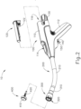
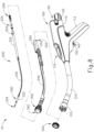
- FIGS. 1-2 depict an exemplary surgical circular stapling instrument (10) that may be used to provide an end-to-end anastomosis between two sections of an anatomical lumen such as a portion of a patient's digestive tract.
- Instrument (10) of this example comprises a handle assembly (100), a shaft assembly (200), a stapling head assembly (300), and an anvil (400).
- Handle assembly (100) comprises a casing (110) defining an obliquely oriented pistol grip (112).
- pistol grip (112) is perpendicularly oriented.
- pistol grip (112) is omitted.
- Handle assembly (110) further includes a window (114) that permits viewing of a movable indicator needle (526) as will be described in greater detail below.
- a series of hash marks, colored regions, and/or other fixed indicators are positioned adjacent to window (114) in order to provide a visual context for indicator needle (526), thereby facilitating operator evaluation of the position of needle (526) within window (114).
- Various suitable alternative features and configurations for handle assembly (112) will be apparent to those of ordinary skill in the art in view of the teachings herein.
- Instrument (10) of the present example further includes a battery pack (120).
- Battery pack (120) is operable to provide electrical power to a motor (160) in pistol grip (112) as will be described in greater detail below.
- Battery pack (120) is removable from handle assembly (100).
- battery pack (120) may be inserted into a socket (116) defined by casing (110). Once battery pack (120) is fully inserted in socket (116), latches (122) of battery pack (120) may resiliently engage interior features of casing (110) to provide a snap fit.
- battery pack (120) may have complementary electrical contacts, pins and sockets, and/or other features that provide paths for electrical communication from battery pack (120) to electrically powered components in handle assembly (100) when battery pack (120) is inserted in socket (116). It should also be understood that, in some versions, battery pack (120) is unitarily incorporated within handle assembly (100) such that battery back (120) cannot be removed from handle assembly (100).
- Shaft assembly (200) extends distally from handle assembly (100) and includes a preformed bend.
- the preformed bend is configured to facilitate positioning of stapling head assembly (300) within a patient's colon.
- shaft assembly (200) is straight, such that shaft assembly (200) lacks a preformed bend.
- Various exemplary components that may be incorporated into shaft assembly (100) will be described in greater detail below.
- Stapling head assembly (300) is located at the distal end of shaft assembly (200). As shown in FIGS. 1-2 and as will be described in greater detail below, anvil (400) is configured to removably couple with shaft assembly (200), adjacent to stapling head assembly (300). As will also be described in greater detail below, anvil (400) and stapling head assembly (300) are configured to cooperate to manipulate tissue in three ways, including clamping the tissue, cutting the tissue, and stapling the tissue.
- a depicts (130) at the proximal end of handle assembly (100) is rotatable relative to casing (110) to provide precise clamping of the tissue between anvil (400) and stapling head assembly (300). When a safety trigger (140) of handle assembly (100) is pivoted away from a firing trigger (150) of handle assembly (100), firing trigger (150) may be actuated to thereby provide cutting and stapling of the tissue.
- distal and proximal will be used with reference to the orientation of anvil (400) when anvil (400) is coupled with shaft assembly (200) of instrument (10).
- proximal features of anvil (400) will be closer to the operator of instrument (10); while distal features of anvil (400) will be further from the operator of instrument (10).
- anvil (400) of the present example comprises a head (410) and a shank (420).
- Head (410) includes a proximal surface (412) that defines a plurality of staple forming pockets (414).
- Staple forming pockets (414) are arranged in two concentric annular arrays. In some other versions, staple forming pockets (414) are arranged in three or more concentric annular arrays. Staple forming pockets (414) are configured to deform staples as the staples are driven into staple forming pockets (414). For instance, each staple forming pocket (414) may deform a generally "U" shaped staple into a "B" shape as is known in the art.
- proximal surface (412) terminates at an inner edge (416), which defines an outer boundary of an annular recess (418) surrounding shank (420).
- Shank (420) defines a bore (422) and includes a pair of pivoting latch members (430) positioned in bore (422).
- each latch member (430) includes a "T" shaped distal end (432), a rounded proximal end (434), and a latch shelf (436) located distal to proximal end (434).
- "T" shaped distal ends (432) secure latch members (430) within bore (422).
- Latch members (430) are positioned within bore (422) such that distal ends (434) are positioned at the proximal ends of lateral openings (424), which are formed through the sidewall of shank (420).
- Lateral openings (424) thus provide clearance for distal ends (434) and latch shelves (436) to deflect radially outwardly from the longitudinal axis defined by shank (420).
- latch members (430) are configured to resiliently bias distal ends (434) and latch shelves (436) to radially inwardly toward the longitudinal axis defined by shank (420). Latch members (430) thus act as retaining clips.
- This allows anvil (400) to be removably secured to a trocar (330) of stapling head assembly (300) as will be described in greater detail below. It should be understood, however, that latch members (436) are merely optional.
- Anvil (400) may be removably secured to a trocar (330) using any other suitable components, features, or techniques.
- anvil (400) may be further constructed and operable in accordance with at least some of the teachings of U.S. Pat. No. 5,205,459 ; U.S. Pat. No. 5,271,544 ; U.S. Pat. No. 5,275,322 ; U.S. Pat. No. 5,285,945 ; U.S. Pat. No. 5,292,053 ; U.S. Pat. No. 5,333,773 ; U.S. Pat. No. 5,350,104 ; U.S. Pat. No. 5,533,661 ; and/or U.S. Pat. No. 8,910, 847 . Still other suitable configurations will be apparent to one of ordinary skill in the art in view of the teachings herein.
- stapling head assembly (300) of the present example is coupled to a distal end of shaft assembly (200) and comprises a tubular casing (310) housing a slidable staple driver member (350).
- a cylindraceous inner core member (312) extends distally within tubular casing (310).
- Tubular casing (310) is fixedly secured to an outer sheath (210) of shaft assembly (200), such that tubular casing (310) serves as a mechanical ground for stapling head assembly (300).
- Trocar (330) is positioned coaxially within inner core member (312) of tubular casing (310). As will be described in greater detail below, trocar (330) is operable to translate distally and proximally relative to tubular casing (310) in response to rotation of knob (130) relative to casing (110) of handle assembly (100).
- Trocar (330) comprises a shaft (332) and a head (334). Head (334) includes a pointed tip (336) and an inwardly extending proximal surface (338). Shaft (332) thus provides a reduced outer diameter just proximal to head (334), with surface (338) providing a transition between that reduced outer diameter of shaft (332) and the outer diameter of head (334).
- tip (336) is pointed in the present example, tip (336) is not sharp. Tip (336) will thus not easily cause trauma to tissue due to inadvertent contact with tissue.
- Head (334) and the distal portion of shaft (332) are configured for insertion in bore (422) of anvil (420).
- Proximal surface (338) and latch shelves (436) have complementary positions and configurations such that latch shelves (436) engage proximal surface (338) when shank (420) of anvil (400) is fully seated on trocar (330). Anvil (400) is thus secured to trocar (330) through a snap fit due to latch members (430).
- Staple driver member (350) is operable to actuate longitudinally within tubular casing (310) in response to activation of motor (160) as will be described in greater detail below.
- Staple driver member (350) includes two distally presented concentric annular arrays of staple drivers (352).
- Staple drivers (352) are arranged to correspond with the arrangement of staple forming pockets (414) described above.
- each staple driver (352) is configured to drive a corresponding staple into a corresponding staple forming pocket (414) when stapling head assembly (300) is actuated.
- the arrangement of staple drivers (352) may be modified just like the arrangement of staple forming pockets (414) as described above.
- Staple driver member (350) also defines a bore (354) that is configured to coaxially receive core member (312) of tubular casing (310).
- An annular array of studs (356) project distally from a distally presented surface surrounding bore (354).
- Knife member (340) is coaxially positioned within staple driver member (350).
- Knife member (340) includes a distally presented, sharp circular cutting edge (342).
- Knife member (340) is sized such that knife member (340) defines an outer diameter that is smaller than the diameter defined by the inner annular array of staple drivers (352).
- Knife member (340) also defines an opening that is configured to coaxially receive core member (312) of tubular casing (310).
- An annular array of openings (346) formed in knife member (340) is configured to complement the annular array of studs (356) of staple driver member (350), such that knife member (340) is fixedly secured to staple driver member (350) via studs (356) and openings (346).
- Other suitable structural relationships between knife member (340) and stapler driver member (350) will be apparent to those of ordinary skill in the art in view of the teachings herein.
- a deck member (320) is fixedly secured to tubular casing (310).
- Deck member (320) includes a distally presented deck surface (322) defining two concentric annular arrays of staple openings (324).
- Staple openings (324) are arranged to correspond with the arrangement of staple drivers (352) and staple forming pockets (414) described above.
- each staple opening (324) is configured to provide a path for a corresponding staple driver (352) to drive a corresponding staple through deck member (320) and into a corresponding staple forming pocket (414) when stapling head assembly (300) is actuated.
- the arrangement of staple openings (322) may be modified just like the arrangement of staple forming pockets (414) as described above.
- deck member (320) defines an inner diameter that is just slightly larger than the outer diameter defined by knife member (340). Deck member (320) is thus configured to allow knife member (340) to translate distally to a point where cutting edge (342) is distal to deck surface (322).
- stapling head assembly (300) may be further constructed and operable in accordance with at least some of the teachings of U.S. Pat. No. 5,205,459 ; U.S. Pat. No. 5,271,544 ; U.S. Pat. No. 5,275,322 ; U.S. Pat. No. 5,285,945 ; U.S. Pat. No. 5,292,053 ; U.S. Pat. No. 5,333,773 ; U.S. Pat. No. 5,350,104 ; U.S. Pat. No. 5,533,661 ; and/or U.S. Pat. No. 8,910, 847 . Still other suitable configurations will be apparent to one of ordinary skill in the art in view of the teachings herein.
- FIG. 8 shows various components of shaft assembly (200), which couples components of stapling head assembly (300) with components of handle assembly (100).
- shaft assembly (200) includes an outer sheath (210) that extends between handle assembly (100) and tubular casing (310).
- outer sheath (210) is rigid and includes a preformed curved section as noted above.
- Shaft assembly (200) further includes a trocar actuation rod (220) and a trocar actuation band assembly (230).
- the distal end of trocar actuation band assembly (230) is fixedly secured to the proximal end of trocar shaft (332).
- the proximal end of trocar actuation band assembly (230) is fixedly secured to the distal end of trocar actuation rod (220). It should therefore be understood that trocar (330) will translate longitudinally relative to outer sheath (210) in response to translation of trocar actuation band assembly (230) and trocar actuation rod (220) relative to outer sheath (210).
- Trocar actuation band assembly (230) is configured to flex such that trocar actuation band assembly (230) may follow along the preformed curve in shaft assembly (200) as trocar actuation band assembly (230) is translated longitudinally relative to outer sheath (210).
- trocar actuation band assembly (230) has sufficient column strength and tensile strength to transfer distal and proximal forces from trocar actuation rod (220) to trocar shaft (332).
- Trocar actuation rod (220) is rigid.
- a clip (222) is fixedly secured to trocar actuation rod (220) and is configured to cooperate with complementary features within handle assembly (100) to prevent trocar actuation rod (220) from rotating within handle assembly (100) while still permitting trocar actuation rod (220) to translate longitudinally within handle assembly (100).
- Trocar actuation rod (220) further includes a coarse helical threading (224) and a fine helical threading (226). Details regarding the movement of trocar actuation rod (220) will be described in greater detail below.
- Shaft assembly (200) further includes a stapling head assembly driver (240) that is slidably received within outer sheath (210).
- the distal end of stapling head assembly driver (240) is fixedly secured to the proximal end of staple driver member (350).
- the proximal end of stapling head assembly driver (240) is secured to a drive bracket (250) via a pin (242). It should therefore be understood that staple driver member (350) will translate longitudinally relative to outer sheath (210) in response to translation of stapling head assembly driver (240) and drive bracket (250) relative to outer sheath (210).
- Stapling head assembly driver (240) is configured to flex such that stapling head assembly driver (240) may follow along the preformed curve in shaft assembly (200) as stapling head assembly driver (240) is translated longitudinally relative to outer sheath (210).
- stapling head assembly driver (240) has sufficient column strength to transfer distal forces from drive bracket (250) to staple driver member (350). Details regarding the movement of drive bracket (250) will be described in greater detail below.
- shaft assembly (200) may further include one or more spacer elements within outer sheath (210).
- spacer elements may be configured to support trocar actuation band assembly (230) and/or stapling head assembly driver (240) as trocar actuation band assembly (230) and/or stapling head assembly driver (240) translate through outer sheath (210).
- spacer elements may prevent trocar actuation band assembly (230) and/or stapling head assembly driver (240) from buckling as trocar actuation band assembly (230) and/or stapling head assembly driver (240) translate through outer sheath (210).
- Various suitable forms that such spacer elements may take will be apparent to those of ordinary skill in the art in view of the teachings herein.
- shaft assembly (200) may be further constructed and operable in accordance with at least some of the teachings of U.S. Pat. No. 5,205,459 ; U.S. Pat. No. 5,271,544 ; U.S. Pat. No. 5,275,322 ; U.S. Pat. No. 5,285,945 ; U.S. Pat. No. 5,292,053 ; U.S. Pat. No. 5,333,773 ; U.S. Pat. No. 5,350,104 ; U.S. Pat. No. 5,533,661 ; and/or U.S. Pat. No. 8,910, 847 . Still other suitable configurations will be apparent to one of ordinary skill in the art in view of the teachings herein.
- handle assembly (100) includes several components that are operable to actuate anvil (400) and stapling head assembly (300). Handle assembly (100) also includes components that are operable to selectively lock out triggers (140, 150) based on the position of anvil (400) relative to stapling head assembly (300). When triggers (140, 150) are locked out, firing trigger (150) is prevented from initiating actuation of stapling head assembly (300). Thus, trigger (150) is only operable to initiate actuation of stapling head assembly (300) when the position of anvil (400) relative to stapling head assembly (300) is within a predefined range.
- the components of handle assembly (100) that provide the foregoing operability will be described in greater detail below.
- Knob (130) protrudes proximally from casing (110) of handle assembly and is rotatable relative to casing (110). As shown in FIG. 9 , a nut (160) is secured to the distal end of knob (130). In the present example, nut (160) is fixedly secured to the distal end of knob (130) such that nut (160) will rotate unitarily with knob (130). Nut (160) and knob (130) are configured to cooperate with trocar actuation rod (220) to thereby translate trocar actuation rod (220) longitudinally relative to casing (110) in response to rotation of nut (160) and knob (130) relative to casing (110). As noted above, trocar (330) will translate longitudinally relative to outer sheath (210) in response to translation of trocar actuation rod (220) relative to outer sheath (210) and casing (110).
- trocar actuation rod (220) is positioned within handle assembly (100) to engage nut (160) and knob (130).
- trocar actuation rod (220) is positioned within handle assembly (100) such that coarse helical threading (224) will selectively engage a thread engagement feature (not shown) within the interior of nut (160); and such that fine helical threading (226) will selectively engage a thread engagement feature (not shown) within the interior of knob (130).
- the thread engagement feature of nut (160) comprises an inwardly directed tab; while the thread engagement feature of knob (130) comprises a helical threading.
- Other suitable forms that such thread engagement features may take will be apparent to those of ordinary skill in the art in view of the teachings herein.
- trocar actuation rod (220) travels proximally through a first range of longitudinal motion where coarse helical threading (224) is engaged with nut (160) to provide a relatively rapid rate of translation. Fine helical threading (226) is not engaged with knob (130) during this range of motion.
- trocar actuation rod (220) will continue to travel proximally through a second range of longitudinal motion where fine helical threading (226) is engaged with knob (130) to provide a relatively slow rate of translation.
- trocar actuation rod (220) will translate proximally through a sequence of rapid translation followed by slow translation, based on engagement between coarse helical threading (224) and nut (160) followed by engagement between fine helical threading (226) and knob (130).
- knob (130) when anvil (400) is coupled with trocar (330), rotation of knob (130) will provide corresponding translation of anvil relative to stapling head assembly (300). It should also be understood that knob (130) may be rotated in a first angular direction (e.g., clockwise) to retract anvil (400) toward stapling head assembly (300); and in a second angular direction (e.g., counterclockwise) to advance anvil (500) away from stapling head assembly (300). Knob (130) may thus be used to adjust the gap distance (d) between opposing surfaces (412, 322) of anvil (400) and stapling head assembly (300) until a suitable gap distance (d) has been achieved as shown in FIG. 21C and as described in greater detail below.
- first angular direction e.g., clockwise
- a second angular direction e.g., counterclockwise
- knob may be used to adjust the gap distance (d) between opposing surfaces (412, 322) of anvil (400) and stapling head assembly (300).
- Setting an appropriate gap distance (d) before actuating stapling head assembly (300) may be critical to the success of an anastomosis. For instance, if the gap distance (d) is too great, the staples that are deployed at the anastomosis site may not be sufficiently formed by staple forming pockets (414). This may result in leakage at the anastomosis site, and in some cases may ultimately lead to the separation of the anatomical lumen sections that are joined at the anastomosis site.
- the gap distance (d) is too small, the internal structure of the tissue compressed between surfaces (412, 322) may be damaged to the point where the structural integrity of the tissue is compromised. This may prevent the tissue from adequately holding the formed staples, which again may result in leakage or other failure of the anastomosis. It may therefore be desirable to provide the operator with some form of feedback indicating whether the gap distance (d) is within an appropriate range. It may also be desirable to prevent the operator from actuating stapling head assembly (300) unless the gap distance (d) is within an appropriate range.
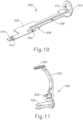
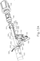
- FIGS. 9-12E show components that provide feedback to the operator to indicate whether the gap distance (d) is within an appropriate range; and prevent the operator from actuating stapling head assembly (300) unless the gap distance (d) is within an appropriate range.
- a bracket (500) is configured and positioned to move in response to movement of trocar actuation rod (220).
- bracket (500) includes a rigid body (502) that defines a first slot (504), a second slot (506), and a third slot (508).
- An upright feature (510) is positioned at the proximal end of body (502) and defines an opening (512).
- Trocar actuation rod (220) extends coaxially through opening (512).
- a coil spring (170) is interposed between the proximal end of upright feature (510) and a rigid bulkhead feature that is defined by casing (110) and that forms a support journal for nut (160).
- the bulkhead is fixed within casing (110) and thereby provides a ground for the proximal end of coil spring (170), such that coil spring (170) resiliently imparts a distal bias to bracket (500) via upright feature (510).
- Bracket (500) further includes a laterally presented flange (516) at the distal end of body (502). Flange (516) defines a slot (514).
- an indicator member (520) is configured to pivot in response to translation of bracket (500).
- indicator member (520) comprises an upright arm (522), a snap pin (524) projecting laterally from a lower end of arm (522), an indicator needle (526) projecting laterally from an upper end of arm (522), and a coupling pin (528) projecting laterally from an intermediate region of arm (522).
- Snap pin (524) is configured to snap into a complementary recess provided by casing (110). Snap pin (524) thereby secures indicator member (520) to casing (110) yet permits indicator member (520) to pivot relative to casing (110) about the longitudinal axis of snap pin (524).
- Indicator needle (526) is positioned to be visible through window (114) of handle assembly (110) to thereby visually indicate the pivotal position of indicator member (520).
- Coupling pin (528) is slidably received in slot (514) of flange (516) of bracket (500). This engagement between indicator member (520), casing (110), and bracket (500) provides pivotal movement of indicator member (520) in response to translation of bracket (500).
- Bracket (500) is configured to selectively prevent and permit actuation of triggers (140, 150).
- slots (504, 506) of bracket (500) are configured to selectively provide clearance for actuation of triggers (140, 150).
- safety trigger (140) is pivotably coupled with a first upright member (144).
- First upright member (144) is coupled with casing (110) such that first upright member (144) is configured to translate upwardly in response to pivoting of safety trigger (140) toward pistol grip (112).
- body (502) of bracket (500) is configured to prevent this movement of first upright member (144) and safety trigger (140) by engaging the upper end (146) of first upright member (144).
- Body (502) thus blocks movement of first upright member (144) and safety trigger (140) until bracket (500) is moved to a position where slot (506) is aligned with upper end (146) to thereby provide clearance for upward movement of first upright member (144). It should therefore be understood that safety trigger (140) cannot be pivoted toward pistol grip (112) until slot (506) is positioned over upper end (146).
- firing trigger (150) is pivotably coupled with a second upright member (154).
- Second upright member (154) is coupled with casing (110) such that second upright member (154) is configured to translate upwardly in response to pivoting of safety trigger (150) toward pistol grip (112).
- body (502) of bracket (500) is configured to prevent this movement of second upright member (154) and firing trigger (150) by engaging the upper end (156) of second upright member (154).
- safety trigger (140) is pivoted out of the way to otherwise permit movement of firing trigger (150
- body (502) blocks movement of second upright member (154) and firing trigger (150) until bracket (500) is moved to a position where slot (504) is aligned with upper end (156) to thereby provide clearance for upward movement of second upright member (154). It should therefore be understood that, even if safety trigger (140) is pivoted out of the way to otherwise permit movement of firing trigger (150), firing trigger (150) cannot be pivoted toward pistol grip (112) until slot (504) is positioned over upper end (156).
- Third slot (508) is configured to receive a downwardly projecting boss (223) of clip (222), which is rigidly secured to trocar actuation rod (220). While casing (110) is configured to allow bracket (500) to translate longitudinally within casing (110), casing (110) includes rails, channels, and/or other features that prevent bracket (500) from rotating within casing (110). Thus, the positioning of boss (223) in slot (508) prevents clip (222) and trocar actuation rod (220) from rotating within casing (110). Boss (223) and slot (508) nevertheless allow bracket (500) to translate longitudinally within casing (110) as will be described in greater detail below.
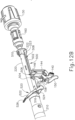
- FIGS. 12A-12E depict the above-described components at various stages of operation.
- trocar actuation rod (220) is in a distal-most position, such that trocar (330) is in a distal-most position.
- the operator may couple anvil (400) with trocar (330) by inserting trocar (330) into bore (422) until latch members (430) are secured to head (334) of trocar (330). The operator then rotates knob (130), which rotates nut (160).
- trocar actuation rod (220) As knob (130) and nut (160) rotate, engagement between coarse helical threading (224) of trocar actuation rod (220) and the complementary feature of nut (160) causes trocar actuation rod (220) to retract proximally at a relatively rapid rate, such that trocar actuation rod (220) reaches the position shown in FIG. 12B .
- This provides proximal retraction of trocar actuation rod (220) provides retraction of trocar (330) and anvil (400).
- bracket (500) remains stationary. This is due to the fact that clip (222) is spaced apart from upright feature (510) at the stage shown in FIG. 12A and does not engage upright feature (510) until trocar actuation rod (220) reaches the position shown in FIG. 12B .
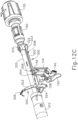
- trocar actuation rod (220) moves from the position shown in FIG. 12B to the position shown in FIG. 12C .
- clip (222) bears against bracket (500), driving bracket (500) proximally.
- This proximal movement of bracket (500) causes indicator member (520) to pivot from the position shown in FIG. 12B to the position shown in FIG. 12C due to the positioning of pin (528) in slot (514) of flange (516).
- indicator member (520) pivots from the position shown in FIG. 12B to the position shown in FIG. 12C , the operator may observe the position of indicator needle (526) through window (114) of handle assembly (110).
- a series of hash marks, colored regions, and/or other fixed indicators may be positioned adjacent to window (114) in order to provide a visual context for indicator needle (526), thereby facilitating operator evaluation of the position of needle (526) within window (114). It should be understood that the position of needle (526) within window (114) will be indicative of the longitudinal position of trocar (330) and anvil (400).
- the position of needle (526) within window (114) will thus indicate the gap distance (d) between opposing surfaces (412, 322) of anvil (400) and stapling head assembly (300). While observing the position of needle (526) within window (114), the operator may rotate knob (130) clockwise or counterclockwise to further retract or advance trocar (330) and anvil (400), thereby providing fine adjustment of the gap distance (d) until a desired gap distance (d) is reached within an appropriate range.
- trocar actuation rod (220) will be at a longitudinal position where fine helical threading (226) is engaged with a complementary feature of knob (130) and coarse helical threading (224) is disengaged from the complementary feature of nut (160).
- coarse helical threading (224) disengages nut (160) and fine helical threading (226) begins to engage knob (130) once trocar actuation rod (220) reaches the longitudinal position shown in FIG. 12B (i.e., when clip (222) first engages upright member (510)).
- the transition from engagement by coarse helical threading (224) to fine helical threading (226) occurs sometime between the stage shown in FIG. 12B and the stage shown in FIG. 12C .
- Other suitable stages at which the coarse-to-fine transition may occur will be apparent to those of ordinary skill in the art in view of the teachings herein.
- some alternative versions of trocar actuation rod (220) may have just a single threading section, with the pitch of the threading being consistent along the length of the threading. In other words, trocar actuation rod (220) does not necessarily need to have two different sections of threading (224, 226) with different pitches.
- slot (506) is aligned with upper end (146) to thereby provide clearance for upward movement of first upright member (144).
- slot (504) is aligned with upper end (156) to thereby provide clearance for upward movement of second upright member (154).
- slots (504, 506) are sized and positioned such that slots (504, 506) only provide clearance for upward movement of upright members (144, 154) when the gap distance (d) is within a clinically acceptable range.
- a "clinically acceptable range" for the gap distance (d) may be between approximately 0.2794 cm (0.11 inches) and approximately 0.1016 cm (0.04 inches).
- a "clinically acceptable range" for the gap distance (d) may be between approximately 0.2794 cm (0.11 inches) and approximately 0.0508 cm (0.02 inches). Even when slots (504, 506) are positioned to provide clearance for upward movement of upright members (144, 154) as shown in FIG. 12C , safety trigger (140) will still block pivotal movement of firing trigger (150) about a pin (152) ( FIG. 9 ) when safety trigger (140) is in the non-actuated position shown in FIG. 12C . Thus, in order to enable movement of firing trigger (150), the operator will need to first actuate safety trigger (140) about a pin (142) ( FIG. 9 ) from the position shown in FIG. 12C to the position shown in FIG. 12D .
- upper end (146) passes through slot (506) as safety trigger (140) is pivoted from the position shown in FIG. 12C to the position shown in FIG. 12D .
- this movement of upper end (146) would not be possible at the stages shown in FIGS. 12A-12B (when the gap distance (d) is too great) because body (502) would physically block upward movement of upright member (144), thereby physically blocking pivotal movement of safety trigger (140).
- a cap (not shown) incorporated into knob (130) prevents knob (130) from rotating to a point where anvil (400) would be retracted too far proximally (such that the gap distance (d) is too small).
- knob (130) In some other variations, even if knob (130) were to permit anvil (400) to be retracted too far proximally (such that the gap distance (d) is too small), body (502) would physically block upward movement of upright member (144), thereby physically blocking pivotal movement of safety trigger (140), in the event that the operator retracts trocar (330) and anvil (400) too far proximally (such that the gap distance (d) is too small). Regardless of whether body (502), knob (130), or some other feature prevents actuation when the gap distance (d) would be too small, it should be understood that instrument (10) permits actuation of safety trigger (140) only when the gap distance (d) is within the clinically acceptable range.
- safety trigger (140) is configured to prevent actuation of firing trigger (150) until safety trigger (140) has been actuated. Once safety trigger (140) has been actuated, the operator may actuate firing trigger (150) from the position shown in FIG. 12D to the position shown in FIG. 12E . As shown in FIG. 12E , upper end (156) passes through slot (504) as firing trigger (150) is pivoted from the position shown in FIG. 12D to the position shown in FIG. 12E . It should be understood that, even in the complete absence of safety trigger (140), this movement of upper end (156) would not be possible at the stages shown in FIGS.
- firing trigger (150) may only be actuated when the gap distance (d) is within the clinically acceptable range.
- Firing trigger (150) of the present example includes an integral actuation paddle (158).
- Paddle (158) pivots forwardly as firing trigger (150) pivots from the position shown in FIG. 12D to the position shown in FIG. 12E .
- Paddle (158) is configured to actuate a switch of a motor activation module (180), which is shown in FIG. 9 , when firing trigger (150) pivots from the position shown in FIG. 12D to the position shown in FIG. 12E .
- Motor activation module (180) is in communication with battery pack (120) and motor (160), such that motor activation module (180) is configured to provide activation of motor (160) with electrical power from battery pack (120) in response to paddle (158) actuating the switch of motor activation module (180).
- motor (160) will be activated when firing trigger (150) is pivoted from the position shown in FIG. 12D to the position shown in FIG. 12E .
- This activation of motor (160) will actuate stapling head assembly (300) as described in greater detail below.
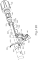
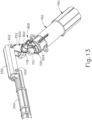
- FIGS. 13-20D show various components that are operable to actuate stapling head assembly (300). These components include motor (160), a gearbox (162), a rotary cam member (700), a cam follower (600), drive bracket (250) and stapling head assembly driver (240). Gearbox (162) is coupled with a drive shaft of motor (160) and is further coupled with cam member (700). Activation of motor (160) thus causes rotation of cam member (700) via gearbox (162).
- gearbox (162) Various suitable configurations that may be used for gearbox (162) will be apparent to those of ordinary skill in the art in view of the teachings herein.
- Cam member (700) is configured to interact with cam follower (160) to pivot cam follower (160) in two angular directions about a pin (118) as will be described in greater detail below.
- Pin (118) is coupled with casing (110).
- a bushing (701) provides rotary support to cam member (700) relative to casing (110).
- Cam follower (600) is pivotably coupled with drive bracket (250) via a pair of integral pins (602), which are received in complementary notches (252) of drive bracket (250). As shown in FIGS. 14-15 , cam follower (600) includes a first bearing feature (604) and a second bearing feature (610).
- First bearing feature (604) consists of a rounded, horizontally extending surface.
- Second bearing feature (610) is shaped like a quarter-pie defined by a straight vertical surface (612), a horizontally extending surface (614), and a curved surface (616). Second bearing feature (610) projects proximally relative to first bearing feature (504).
- FIGS. 16-17 show cam member (700) in greater detail.
- Cam member (700) comprises a distal face (702), a distally projecting post (704), and an outer circumferential surface (706).
- a first cam feature (710) and a second cam feature (720) project distally from distal face (702).
- Post (704) engages bushing (701).
- First cam feature (710) comprises a first surface region (712), a second surface region (714), and a third surface region (716).
- First surface region (712) is convexly defined by a relatively large radius of curvature, such that first surface region (712) is nearly flat.
- Second surface region (714) is convexly defined by a progressively increasing radius of curvature.
- Third surface region (716) is concavely defined by a relatively large radius of curvature.
- second cam feature (720) projects outwardly from outer circumferential surface (706).
- Second cam feature (720) includes a first surface region (722) and a second surface region (724).
- First surface region (722) is substantially flat while second surface region (724) is concavely curved.
- the origin of the radius of curvature for each curved surface region (712, 714, 716, 724) is offset from the center of post (704).
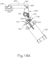
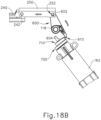
- FIGS. 18A-18B show the general interaction between cam follower (600) and first and second cam features (710, 720), though this interaction will be described in greater detail below with reference to FIGS. 20A-20D .
- first cam feature (710) bears against first bearing feature (604) of cam follower (600), causing cam follower to pivot about pin (118).
- cam follower (600) pivots counterclockwise as cam member (700) is rotated from the position shown in FIG. 18A to the position shown in FIG. 18B .
- cam follower (600) drives drive bracket (250) and stapling head assembly driver (240) distally, thereby actuating stapling head assembly (300).
- cam member (700) continues to rotate in the same direction back toward the position shown in FIG. 18A
- second cam feature (720) engages and bears against second bearing feature (610) of cam follower (600), causing cam follower (600) to pivot clockwise about pin (118).
- This clockwise pivoting of cam follower (600) about pin (118) retracts drive bracket (250) and stapling head assembly driver (240) proximally back toward the position shown in FIG. 18A .
- a third cam feature (730) projects outwardly from outer circumferential surface (706).
- Third cam feature (730) comprises a first surface region (732) and a second surface region (734).
- First surface region (732) is flat and is oriented generally tangentially relative to outer circumferential surface (706).
- Second surface region (732) is also flat and is oriented radially outwardly relative to outer circumferential surface (706).
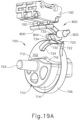
- Third cam feature (730) is configured to interact with a rocker member (800) as shown in FIGS. 19A-19B .
- Rocker member (800) comprises an integral pin (802), a bearing member (804), and a paddle (806).
- Pin (802) is pivotably coupled with casing (110), such that rocker member (800) is pivotable within casing (110) about the longitudinal axis defined by pin (802).
- Bearing member (804) is configured to interact with third cam feature (730) as will be described in greater detail below.
- Paddle (806) is configured to actuate a switch button (192) of a short circuit module (190) as will also be described in greater detail below.
- FIG. 19A shows cam member (700) in the same position as shown in FIG. 18A .
- second surface region (734) of third cam feature (730) is adjacent to bearing member (804) of rocker member (800).
- FIG. 19B shows cam member (700) in a position where cam member (700) has been rotated past the position shown in FIG. 18B and back toward the position shown in FIG. 18A .
- cam member (700) has not completed a full revolution.
- first surface region (732) has engaged and borne against bearing member (804), thereby pivoting rocker member (800) about the longitudinal axis defined by pin (802). This has caused paddle (806) to actuate switch button (192) of short circuit module (190).
- Short circuit module (190) is configured to prevent motor (160) from further activation when switch button (192) has been actuated.
- short circuit module (190) couples battery pack (120) with a power sink, in addition to short circuiting motor (160), when switch button (192) is actuated. This may result in discharge of battery pack (120) in addition to stopping activation of motor (160) once an actuation stroke of stapling head assembly (300) has been completed.
- short circuit module (190) may be configured and operable in accordance with at least some of the teachings of U.S. Pub. No. 2015/0083774 . Other suitable configurations will be apparent to those of ordinary skill in the art in view of the teachings herein.
- FIGS. 20A-20D schematically depict the interaction between cam member (700), features of cam follower (600), and features of rocker member (800) as cam member (700) rotates. It should be understood that the rotation of cam member (700) throughout the stages shown in FIGS. 20A-20D is driven by motor (160) and gearbox (162).
- FIG. 20A shows cam member (700) in the same position as shown in FIGS. 18A and 19A .
- first bearing feature (604) of cam follower (600) is positioned on first surface region (712) and bearing member (804) or rocker member (800) is adjacent to second surface region (734) of third cam feature (730).
- knife member (340) and staple driver member (350) are in proximal positions, such that stapling head assembly (300) is in a non-actuated state.
- cam member (700) is rotated to the position shown in FIG. 20B , second surface region (714) bears against bearing member (804), thereby driving bearing member (804) upwardly.
- cam follower (600) to pivot about pin (118) to the position shown in FIG. 18B .
- Cam follower (600) thus drives knife member (340) and staple driver member (350) distally via drive bracket (250) and stapling head assembly driver (240).
- Stapling head assembly (300) is thus in an actuated state at the stage shown in FIG. 20B .
- cam member (700) rotates through an angular range of approximately 270° in order to transition stapling head assembly (300) from the non-actuated state to the actuated state.
- cam member (700) continues to rotate to the position shown in FIG. 20C .
- first surface region (722) of second cam member (720) begins to engage curved surface (616) of second bearing feature (610) of cam follower (600).
- second surface region (724) engages curved surface (616) of second bearing feature (610), driving second bearing feature (610) downwardly. This causes cam follower (600) to pivot about pin (118) back from the position shown in FIG. 18B toward the position shown in FIG. 18A .
- Cam follower (600) thus drives knife member (340) and staple driver member (350) proximally via drive bracket (250) and stapling head assembly driver (240).
- first surface region (732) has engaged and borne against bearing member (804), thereby pivoting rocker member (800) about the longitudinal axis defined by pin (802) at the stage shown in FIG. 20D .
- Rocker member (800) is thus in the same state in FIG. 20D as shown in FIG. 19B .
- Short circuit module (190) has thus been actuated at the stage shown in FIG. 20D .
- cam member (700) is operable to drive knife member (340) and staple driver member (350) distally, then drive knife member (340) and staple driver member (350) proximally and actuate short circuit module (190) by rotating in a single angular direction through the range of motion shown in FIGS. 20A-20D .
- Other suitable ways in which knife member (340), staple driver member (350), and short circuit module (190) may be actuated will be apparent to those of ordinary skill in the art in view of the teachings herein.
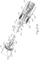
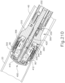
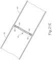
- FIGS. 21A-21E show instrument (10) being used to form an anastomosis (70) between two tubular anatomical structures (20, 40).
- the tubular anatomical structures (20, 40) may comprise sections of a patient's esophagus, sections of a patient's colon, other sections of the patient's digestive tract, or any other tubular anatomical structures.
- anvil (400) is positioned in one tubular anatomical structure (20) and stapling head assembly (300) is positioned in another tubular anatomical structure (40).
- tubular anatomical structures (20, 40) comprise sections of a patient's colon
- stapling head assembly (300) may be inserted via the patient's rectum.
- FIGS. 21A-21E the procedure depicted in FIGS. 21A-21E is an open surgical procedure, though the procedure may instead be performed laparoscopically.
- instrument (10) may be used to form an anastomosis (70) in a laparoscopic procedure will be apparent to those of ordinary skill in the art in view of the teachings herein.
- anvil (400) is positioned in tubular anatomical structure (20) such that shank (420) protrudes from the open severed end (22) of tubular anatomical structure (20).
- a purse-string suture (30) is provided about a mid-region of shank (420) to generally secure the position of anvil (400) in tubular anatomical structure (20).
- stapling head assembly (300) is positioned in tubular anatomical structure (40) such that trocar (330) protrudes from the open severed end (42) of tubular anatomical structure (20).
- a purse-string suture (50) is provided about a mid-region of shaft (332) to generally secure the position of stapling head assembly (300) in tubular anatomical structure (40).
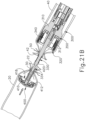
- anvil (400) is secured to trocar (330) by inserting trocar (330) into bore (422) as shown in FIG. 21B .
- Latch members (430) engage head (334) of trocar (330), thereby providing a secure fit between anvil (400) and trocar (330).
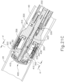
- the operator then rotates knob (130) while holding casing (110) stationary via pistol grip (112). This rotation of knob (130) causes trocar (330) and anvil (400) to retract proximally (as described above with reference to FIGS. 12A-12C ). As shown in FIG.
- this proximal retraction of trocar (330) and anvil (400) compresses the tissue of tubular anatomical structures (20, 40) between surfaces (412, 322) of anvil (400) and stapling head assembly (300).
- the operator observes the position of needle (526) within window (114) to determine whether the gap distance (d) between opposing surfaces (412, 322) of anvil (400) and stapling head assembly (300) is appropriate; and makes any necessary adjustments via knob (130).
- knife member (340) translates distally, cutting edge (342) of knife member (340) cooperates with inner edge (416) of anvil (400), thereby shearing excess tissue that is positioned within annular recess (418) of anvil (400) and the interior of knife member (340).
- anvil (400) of the present example includes a breakable washer (417) within annular recess (418).
- This washer (417) is broken by knife member (340) when the knife member (340) completes a full distal range of motion from the position shown in FIG. 21C to the position shown in FIG. 21D .
- the progressively increasing radius of curvature of second surface region may provide an increasing mechanical advantage as knife member (340) reaches the end of its distal movement, thereby providing greater force by which to break the washer (417).
- the breakable washer (417) may be omitted entirely in some versions.
- washer (417) may also serve as a cutting board for knife member (340) to assist in cutting of tissue.
- Such a cutting technique may be employed in addition to or in lieu of the above-noted shearing action between inner edge (416) and knife member (340).
- staple driver member (350) drives staples (90) through the tissue of tubular anatomical structures (20, 40) and into staple forming pockets (414) of anvil (400). Staple forming pockets (414) deform the driven staples (90) into a "B" shape as is known in the art. The formed staples (90) thus secure the ends of tissue together.
- instrument (10) may be removed via the patient's rectum.
- tubular anatomical structures (20, 40) With instrument (10) is removed, the tubular anatomical structures (20, 40) are left secured together by two annular arrays of staples (90) at an anastomosis (70) as shown in FIG. 21E .
- the inner diameter of the anastomosis (70) is defined by the severed edge (60) left by knife member (340).
- stapling head assembly (300) it may be desirable for an operator to verify complete actuation of stapling head assembly (300).
- the following are merely illustrative examples of various ways to indicate when the firing of staple driver member (350) and knife member (340) has been completed. Other variations or appropriate combinations of present examples and/or other variations will be apparent to one having ordinary skill in the art in view of the teachings herein.
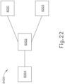
- FIG. 22 depicts a block diagram of an exemplary system (6000) that may be readily incorporated into instrument (10) in order to indicate when stapling head assembly (300) has been fully actuated.
- System (6000) of this example comprises a microprocessor (6002) that is in communication with a power source (6001), a motor (6003), and an indicator (6004).
- Power source (6001) is configured to provide electrical power to motor (6003) when an operator activates the appropriate firing mechanisms (not shown).
- motor (6003) may comprise motor (160) described above; and power source (6001) may comprise battery pack (120) described above.
- Indicator (6004) may be located anywhere on, within, or near the instrument in order to appropriately communicate information to an operator.
- indicator (6004) could comprise an auditory feedback feature (capable of generating a variety of sounds when activated) that is located inside or outside surgical instrument.
- indicator (6004) may include an LED light located within a translucent portion of the body of instrument, capable of emitting light outside surgical stapler to communicate information to operator.
- Indicator (6004) could also be positioned outside the body of instrument in such a manner to communicate appropriate information to operator.
- Indicator (6004) could also comprise an LCD screen attached to the body of instrument or separated from instrument.
- indicator (6004) is viewable through window (114) or is otherwise placed at the location of window (114).
- Various suitable forms that indicator (6004) may take, as well as various places where indicator (6004) may be located, will be apparent to those of ordinary skill in the art in view of the teachings herein.
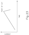
- Microprocessor (6002) is electrically coupled to both power source (6001) and motor (6003). Therefore, microprocessor (6002) is capable of measuring the electrical current supplied from power source (6001) to motor (6003). Of course, any other means of measuring current could be utilized instead of microprocessor (6002). As best shown in FIG. 23 , current supplied from power source (6001) to motor (6003) increases once appropriate firing mechanisms have been activated. Once motor has completed its course of travel, as exemplified in FIG. 20D , power source (6001) is no longer driving staple driver member (350) or knife member (340). This is shown approximately around the point of cut shown on FIG. 23 . Because power source (6001) is no longer driving staple driver member (350) or knife member (340), the current level measured by microprocessor (6002) drops as compared to when power source (6001) was powering motor (6003).
- microprocessor (6002) detects a drop in current associated with completion of actuation of stapling head assembly (300)
- microprocessor (6002) then activates indicator (6004).
- Indicator (6004) thus signals to an operator that the current level of power provided from power source (6001) to motor (6003) has dropped, signifying a completion of actuation of stapling head assembly (300). It should be noted that while microprocessor (6002) measures current supplied from power source (6001) to motor (6003), microprocessor (6002) does not have to strictly measure current or be connected to both power source (6001) and motor (6003) in order to determine completion of the firing process.
- microprocessor (6002) could be in communication with only power source (6001) and indicator (6004) and measure the drop in potential of power source (6001) caused by activation of motor (6003).
- Other suitable configurations and techniques that may be used to measure activation and deactivation of motor (6003) will be apparent to a person having ordinary skill in the art in view of the teachings herein.
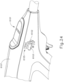
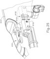
- FIGS. 24-25 depict various features that may be utilized to verify complete actuation of stapling head assembly (300). These features may be readily incorporated into instrument (10). Instead of measuring electrical properties between supply source (6001) and motor (6003), the features depicted in FIGS. 24-25 measure the physical positioning of components that actuate stapling head assembly (300). It should be understood that the physical location of components that actuate stapling head assembly (300) may indicate whether stapling head assembly (300) is in a fired state or an un-fired state.
- FIG. 24 shows a casing (6107), an indication light (6101), a transparent indicator window (6105), and an indicator marking (6102) located on drive bracket (6103).
- casing (6107) is substantially similar to casing (110) mentioned above.
- drive bracket (6103) is substantially similar to drive bracket (250) mentioned above.
- Transparent indicator window (6105) and indicator marking (6102) are used in tandem to visually display the physical location of drive bracket (6103).
- Transparent indicator window (6105) and casing (6107) include fixed markings that provide reference points to compare the location of indicator marking (6102) against in order to determine the position of drive bracket (6103). It should be understood that, based on the location of indicator marking (6102) relative to the predetermined markings on transparent indicator window (6105) and casing (6107), an operator may determine if stapling head assembly (300) has completed actuation.
- drive bracket (6103) when stapling head assembly (300) is in an unfired state, drive bracket (6103) will be in a proximal position, such that indicator marking (6102) will also be in a proximal position. In the proximal position, indicator marking (6102) will be viewable though transparent indicator window (6105) adjacent to an "X" or some other indication, thereby indicating to the operator that stapling head assembly (300) is in an unfired state.
- drive bracket (6103) When stapling head assembly (300) is in a fired state or has been fired, drive bracket (6103) will be advanced to a distal position, such that indicator marking (6102) will also be advanced to a distal position. In the distal position, indicator marking (6102) will be viewable through transparent indicator window (6105) adjacent to a check mark or some other indication, therefore indicating to the operator that stapling head assembly (300) has been fired.
- Indicator light (6101) works separately and independently from indicator marking (6102) and transparent indicator window (6105). It should therefore be understood that an instrument may include indicator light (6101) yet lack indicator marking (6102) and transparent indicator window (6105). Similarly, an instrument may include indicator marking (6102) and transparent indicator window (6105) yet lack indicator light (6101). As shown in FIG. 25 , in the present example indicator light (6101) is in communication with a switch (6106) via wiring (6107). Indicator light (6101) and switch (6106) are both secured to casing (6107). Switch (6106) is operable to pivot based on contact with a protrusion (6104). Pivoting of switch (6106) will activate indicator light (6101), such that indicator light (6101) will illuminate when protrusion (6104) actuates switch (6106). Indicator light (6101) may be configured to illuminate at different colors based on the angular direction that switch (6106) is pivoted, or for any other reason that would be apparent to a personal having ordinary skill in the art in view of the teachings herein.
- Protrusion (6104) is fixed to drive bracket (6103). Protrusion (6104) extends from drive bracket (6103) at a location such that protrusion (6104) will actuate switch (6106) based on the firing status of stapling head assembly (300). For instance, when stapling head assembly (300) is in an unfired state, drive bracket (6103) will be in a proximal position. Therefore, protrusion (6104) will also be in a proximal position such that protrusion (6104) is spaced away from switch (6106).
- indicator light (6101) remains turned off (i.e., non-illuminated), thereby indicating to an operator that stapling head assembly (300) is in an unfired state.
- drive bracket (6103) will be moved to a distal position, such that protrusion (6104) will also be moved to a distal position.
- protrusion (6104) will rotate switch (6106) in a first angular direction. Because protrusion (6104) has rotated switch in a first angular direction, indicator light (6101) illuminates at a first color of light, thereby indicating to the operator that stapling head assembly (300) has been fired.
- protrusion (6104) may be configured to actuate switch (6106) a second time when drive bracket (6103) returns to the proximal position after stapling head assembly (300) has stapled and severed tissue. If protrusion (6104) is positioned on drive bracket (6103) in this manner, protrusion will (6104) translate from a distal position back to a proximal position, therefore rotating switch (6106) in a second angular direction that is opposite to the direction in which switch (6106) rotates during distal translation of drive bracket (6103).
- indicator light (6101) may illuminate at a second color of light, thereby indicating to the operator that the full stroke for stapling head assembly (300) has been completed.
- protrusion (6104) may rotate switch (6106) in a first angular direction to indicate when stapling and severing tissue occurs, then protrusion (6104) may rotate switch (6106) in a second angular direction to indicate when stapling head assembly (300) has completed its entire course of travel.
- switch (6106) may be configured to only light up only when protrusion (6104) has rotated switch (6106) in either a first angular direction or a second angular direction.
- Switch (6106) may be capable of only lighting up indicator light (6101) with one color, but blinking when rotating in a first angular direction and remaining lit when rotating in a second-opposite angular direction.
- Indicator light (6101) might use other forms of indicating, such as auditory rather than visual.
- Other suitable variations will be apparent to one having ordinary skill in the art in view of the teachings herein.
- knob (130) As mentioned above, after the operator has actuated stapling head assembly (300) as shown in FIG. 21D , the operator rotates knob (130) to drive anvil (400) distally away from stapling head assembly (300), increasing the gap distance (d) to facilitate release of the tissue between surfaces (412, 322). The operator then removes instrument (10) from the patient, with anvil (400) still secured to trocar (330). In some instances, it may be desirable for an operator to know when knob (130) has been sufficiently rotated to have driven anvil (400) far enough away from stapling head assembly (300) in order to increase an appropriate gap distance (d) to facilitate release of tissue between surfaces (412, 322).
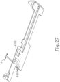
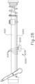
- FIGS. 26-28 depict a switch system (6200) that is operable to indicate a sufficient gap distance (d) to facilitate proper release of stapled tissue between surface (412, 322) of anvil (400) and stapling head assembly (300).
- Switch system (6200) may be readily incorporated into instrument (10).
- Switch system (6200) comprises a trocar actuation rod (6201), a bracket (6202) coupled with trocar actuation rod (6201), a switch (6205) fixed to casing (6206), a counter (6207) and an indicator (6208).
- Trocar actuation rod (6201) is substantially similar to trocar actuation rod (220) mentioned above.
- bracket (6202) is substantially similar to bracket (500) mentioned above. However, bracket (6202) of this example further comprises a linear array of markers (6203) that are arranged in a longitudinally extending array along a path that is parallel with the longitudinal direction defined by trocar actuation rod (6201). Bracket (6202) is configured and positioned to move longitudinally in response to longitudinal movement of trocar actuation rod (6201).
- Adjacent markers (6203) of the linear array of markers (6203) are positioned equidistantly apart. Markers (6203) are positioned along bracket (6202) in order to compress and release switch (6205) while trocar actuation rod (6201) distally actuates trocar (330) away from stapling head assembly (300) to create a sufficient gap distance (d) to release tissue. In other words, markers (6203) are driven distally with bracket (6202) and trocar actuation rod (6201), markers (6203) successively engage fixed switch (6205). In some versions, markers (6203) physically press against switch (6205) and thereby actuate switch (6205) through direct contact. In some other versions, switch (6205) comprises a proximity sensor, an optical sensor, or some other kind of sensor that is responsive to passage of markers (6203) over switch (6205) without necessarily having to come into direct contact with markers (6203).
- Switch (6205) is coupled to a counter (6207) (which may be similar to microprocessor (6002)) via wiring (6204).
- Counter (6207) counts the number of times markers (6203) compress and release switch (6205). Since markers (6203) are spaced apart equidistantly, each compression and release of switch (6205) correlates to a predetermined distance (y) of travel by bracket (6202), trocar actuation rod (6201) and anvil (400). Therefore, once switch (6205) is compressed and released a predetermined number of times, counter (6207) will be able to determine when a sufficient gap distance (d) is created to facilitate release of tissue between surfaces (412, 322).
- markers (6203) are distanced far enough from each other to allow switch (6205) to fully compress and release, thereby ensuring each segment of predetermined distance (y) is accounted for by counter (6207).
- switch (6205) is currently shown as being linearly actuated, switch may also count marks through angular rotation or any other means apparent to one having ordinary skill in the art in view of the teachings herein.
- linear array of markers (6203) can be substituted for one marker (6203) that is placed to engage switch (6405) precisely at the point where a sufficient gap distance (d) is defined for safe removal of tissue from surfaces (412, 322) of anvil (400) and stapling head assembly (300).
- indicator (6207) activates indicator (6208). Activation of indicator (6208) may indicate to the operator that a sufficient gap distance (d) has been created to release tissue between surfaces (412, 322). The operator may then remove instrument (10) from the patient.
- indicator (6208) may provide an audible tone, an automated voice response, a textual indication, a graphical indication, illumination of a light, vibration of pistol grip (112), and/or any other suitable form of audible, visual, and/or tactile feedback.
- Various suitable forms that indicator (6208) may take will be apparent to one of ordinary skill in the art in view of the teachings herein.
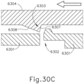
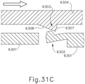
- FIGS. 29-31C depict an exemplary knob detent indicator (6300) that is operable to indicate a sufficient gap distance (d) to facilitate proper release of stapled tissue between surface (412, 322) of anvil (400) and stapling head assembly (300).
- Knob detent indicator (6300) may be readily incorporated into instrument (10).
- knob detent indicator (6300) comprises a knob (6304), a handle assembly (6301), and a proximal shaft segment (6305) unitarily coupled to a distal shaft segment (6306).
- Handle assembly (6301) is substantially similar to handle assembly (100) mentioned above, except that handle assembly (6301) comprises a resilient tab (6302) that is configured to interact with knob (6304) as will be described in greater detail below.
- Tab (6302) extends proximally from handle assembly (6301) and is oriented along a circumferential path.
- Knob (6304) is substantially the same as knob (130) described above, except that knob (6304) further comprises an annular array of detents (6303) configured to interact with resilient tab (6306) of handle assembly (6301) as will be described in greater detail below.
- Detents (6303) extend distally from knob (6304) and are arranged in an annular array at a radius corresponding to the location of tab (6302) in relation to the longitudinal axis shared by shaft segments (6305, 6306).
- Proximal shaft segment (6305) and distal shaft segment (6306) unitarily connect knob (6304) with nut (160) so knob (6304) and nut (160) rotate together unitarily as described above.
- knob (6304) is annularly spaced apart in equal angular segments and are configured to interact with resilient tab (6302) to provide an audible/tactile response in the form of a "click" when each individual detent (6303) passes over resilient tab (6302).
- detents (6303) are spaced apart in equal angular segments, each time a detent (6303) and resilient tab (6302) interact to provide an audible/tactile click, the operator may thus be informed that trocar actuation rod (220) has traveled a predetermined distance in either a proximal direction or a distal direction depending on the direction of rotation. Since the operator can determine how far trocar actuation rod (220) has traveled based on audible/tactile feedback from detents (6303) and resilient tab (6302), the operator can determine when a sufficient gap distance (d) is created to facilitate proper release of stapled tissue by counting a predetermined number of audible/tactile clicks associated with a sufficient gap distance (d).
- the operator may confirm that a sufficient gap distance (d) has been created to release tissue between surfaces (412, 322) of anvil (400) and stapling head assembly (300). The operator may thus be informed that anvil (400) has reached a position where it is proper to remove instrument (10) from the patient.
- trocar actuation rod (220) is more relevant than proximal actuation of trocar actuation rod (220) when creating sufficient gap distance (d) to facilitate proper release of stapled tissue
- creating different audible/tactile responses based off direction of knob (6304) rotation is completely optional.
- annular array of detents (6303) is configured to interact with resilient tab (6302) of handle (6301) to make relatively loud or pronounced clicks when rotation of knob (6304) translates trocar actuation rod (220) in a distal direction.
- Each detent (6303) is defined by a gradual slope (6308) extending obliquely from the distal face of knob (6304) and a steep slope (6307) extending either normal or obliquely from the distal face of knob (6304).
- gradual slope (6308) makes contact with resilient tab (6302), displacing resilient tab a predetermined distance based on the apex of detent (6303).
- annular array of detents (6303) is configured to interact with resilient tab (6302) of handle (6301) to make relatively soft or subdued clicks when rotation of knob (6304) translates trocar actuation rod (220) in a proximal direction.
- FIGS. 31A-B show knob (6304) rotated in a second direction (opposite to the first direction associated with FIGS. 30A-30C ) so that steep slope (6307) displaces resilient tab to the predetermined apex of detent (6303).
- FIG. 31A-B show knob (6304) rotated in a second direction (opposite to the first direction associated with FIGS. 30A-30C ) so that steep slope (6307) displaces resilient tab to the predetermined apex of detent (6303).
- resilient tab (6302) when steep slope (6307) is no longer in contact with resilient tab (6302), resilient tab (6302) is gradually placed back a non-deformed state through contact with gradual slope (6308).
- the gradual release of resilient tab (6302) makes a 'soft' click as compared to the ⁇ loud' click when knob (6303) is rotated in the first direction. Therefore, an operator will be able to determine which direction trocar actuation rod (220) is translating based on the sound of the click, and will also be able to determine the distance traveled by trocar actuation rod (220) based on the number of clicks that are heard and/or felt.
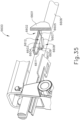
- FIGS. 32A-32B depict a hall effect sensor indicator system (6400) that is operable to indicate a sufficient gap distance (d) to facilitate proper release of stapled tissue between surfaces (412, 322) of anvil (400) and stapling head assembly (300).
- Hall Effect sensor indicator system (6400) may be readily incorporated into instrument (10).
- Hall Effect sensor indicator system (6400) comprises a Hall Effect sensor (6401), a trocar actuation rod (6404), a magnet (6405), and an indicator (6407) attached to knob (6406).
- Hall Effect sensor (6401) is fixed relative to a casing (6402).
- Hall Effect sensor (6401) is connected to indicator (6407) via wiring (6403) such that Hall Effect sensor (6401) effectively acts as a switch to activate indicator (6407) as will be described in greater detail below.
- Knob (6406), casing (6402), and trocar actuation rod (6404) are substantially the same as knob (130), casing (110), and actuation rod (220) mentioned above. Therefore, it should therefore be understood that trocar (330) will translate longitudinally relative to outer sheath (210) in response to translation of trocar actuation rod (6404) relative to outer sheath (210). Additionally, rotation of knob (6406) translates trocar actuation rod (6404).
- magnet (6405) is strategically fixed to trocar actuation rod (6404) such that Hall Effect sensor (6401) is directly adjacent to magnet when trocar actuation rod (6404) is positioned in such a way to define a sufficient gap distance (d) to facilitate proper release of stapled tissue.
- Hall Effect sensor (9401) acts as a switch to turn on indicator (6407). Therefore, when Hall Effect sensor (9401) is not adjacent to magnet, the switch is effectively off, leaving indicator (6407) in an inactivated state. However, when Hall Effect sensor (6401) is directly adjacent to magnet, the switch is effectively on, turning indicator (6407) into an activated state.
- indicator (6407) comprises an LED that illuminates when magnet (6405) actuates Hall Effect sensor (9401).
- indicator (6407) may take any other suitable form and may provide feedback to the operator in the form of audible, visual, and/or tactile feedback.
- trocar actuation rod (6404) when tissue has been severed and staples administered, an operator may start rotating knob to push trocar actuation rod (6404) in a distal direction to facilitate proper release of stapled tissue.
- trocar actuation rod (6404) As trocar actuation rod (6404) travels in the distal direction, magnet (6405) travels closer towards Hall Effect sensor (6401).
- trocar actuation rod (6404) is positioned in such a way to define a sufficient gap distance (d) to facilitate proper release of stapled tissue.
- Hall Effect sensor (6401) switches indicator (6407) to an activated state, allowing operator to confirm that a sufficient gap distance (d) has been created to release tissue between surfaces (412, 322) of anvil (400) and stapling head assembly (300). The operator may thus be informed that anvil (400) has reached a position where it is proper to remove instrument (10) from the patient.
- FIGS. 33-34C depict an exemplary deployable indicator system (6500) that provides audible feedback to indicate a sufficient gap distance (d) to facilitate proper release of stapled tissue between surfaces (412, 322) of anvil (400) and stapling head assembly (300).
- Deployable indicator system (6500) may be readily incorporated into instrument (10).
- Deployable indicator system (6500) comprises a rotary cam feature (6512) that is driven by gearbox (6502), a clicking mechanism (6509) that is slidably coupled to casing (6508), a resilient member (6507) with one end engaging clicking mechanism (6509) and one end fixed to casing (6508), and a bracket (6511).
- Gearbox (6502) is substantially similar to gearbox (162) in the fact gearbox (6502) is driven by motor (not shown) and drives rotary cam member (6512) to drive stapling head assembly (300).
- Rotary cam member (6512) in substantially similar to rotary cam member (700) described above.
- Rotary cam member (6512) comprises a first cam feature (6503), a second cam feature (6513), and a third cam feature (not shown) substantially similar to the first cam feature (710), second cam feature (720), and a third cam feature (730) of rotary cam member (700), respectively.
- cam member (6512) of the present example comprises an additional fourth cam feature (6505). As best seen in FIGS.
- fourth cam feature (6505) slopes in a radial path on top of first cam feature (6503) in such a way that the sloped face of fourth cam feature (6505) engages the proximal end of clicking mechanism (6509) when rotary cam member (6512) is driven by gearbox (6502).
- Bracket (6511) is substantially similar to bracket (500) described above. Bracket (6511) is configured and positioned to translate longitudinally in response to movement of trocar actuation rod (6514). Trocar actuation rod (6514) is substantially similar to trocar actuation rod (220) described above. It should therefore be understood that trocar (330) and anvil (400) will translate longitudinally relative to outer sheath (210) in response to translation of trocar actuation rod (6514) relative to outer sheath (210). Unlike bracket (500) described above, bracket (6511) of the present example also comprises a set of teeth (6510) positioned in a longitudinally extending array that is parallel with the longitudinal direction defined by trocar actuation rod (6514). As will be described in greater detail below, teeth (6510) are configured to engage clicking mechanism (6509) when clicking mechanism (6509) is in a deployed position.
- clicking mechanism (6509) is slidably coupled to casing (6508) in such a way that clicking mechanism (6509) can slide along a linear path.
- Resilient member (6507) has one end fixed to casing (6508) and another end fixed to clicking mechanism (6509).
- resilient member (6507) biases clicking mechanism (6509) toward cam feature (6505) and away from bracket (6511) so that clicking mechanism (6509) is resiliently biased to disengage from linear array of teeth (6510) in a pre-deployed position.
- FIGS. 34A-34C depict the above-described components at various stages of operation.
- FIG. 34A shows deployable indicator system (6500) in a pre-deployed position. In a pre-deployed position, clicking mechanism (6509) is biased in a proximal position away from bracket (6511).
- Rotary cam member (6512) is positioned in a similar position as that of cam member (700) shown in FIGS. 18A , 19A , and 20A . Therefore, at this stage, knife member (340) and staple driver member (350) are in proximal positions, such that stapling head assembly (300) is in a non-actuated state.
- FIG. 34B shows deployable indicator system (6500) in a post-deployed position.
- rotary cam member (6512) is positioned in a similar position as that of cam member (700) shown in FIG. 20D . Therefore, at this state, knife member (340) and staple driver member (350) have been actuated both distally and proximally, completing the cutting and stapling motion.
- fourth cam feature (6505) has been rotated such that the sloped face of fourth cam feature (6505) engages clicking mechanism (6509), thereby displacing clicking mechanism (6509) in a distal direction toward bracket (6511) in opposition to the bias provided by resilient member (6507). It is important to note, at this point, clicking mechanism (6509) is positioned at a level capable of interacting with linear array of teeth (6510) if bracket (6511) is translated longitudinally.
- FIG. 34C shows deployable indicator system (6500) in a post-deployed position while bracket (6511) is being actuated via trocar actuation rod (6514) and knob (130).
- the distal end of clicking mechanism (6509) is in contact with linear array of teeth (6510) such that linear actuation of bracket (6511) drags teeth (6510) over clicking mechanism (6509) to make an audible noise.
- clicking mechanism (6509) provides a pawl that ratchets along teeth (6510) as bracket (6511) translates longitudinally.
- Teeth (6510) may be positioned along bracket (6511) such that any audible clicking between teeth (6510) and deployed clicking mechanism (6509) indicate to the operator that a sufficient gap distance (d) has been created to release tissue between surfaces (412, 322) of anvil (400) and stapling head assembly (300), signaling that removal of instrument is proper. Additionally, teeth (6510) may be positioned along bracket (65111) such that a predetermined number of clicks between teeth (6510) and deployed clicking mechanism (6509) will indicate to the operator that a sufficient gap distance (d) has been created to release tissue between surfaces (412, 322) of anvil (400) and stapling head assembly (300), thereby indicating that that removal of instrument (10) from the patient is proper.
- FIGS. 35-36C depict an exemplary resistance indicator system (6600) that is operable to indicate a sufficient gap distance (d) to facilitate proper release of stapled tissue between surfaces (412, 322) of anvil (400) and stapling head assembly (300).
- Resistance system (6600) may be readily incorporated into instrument (10).
- Resistance indicator system (6600) comprises a trocar actuation rod (6606) and a resistance spring (6612) that is partially fixed to a casing (6601).
- Trocar actuation rod (6606) is substantially similar to trocar actuation rod (220) described above. It should therefore be understood that trocar (330) and anvil (400) will translate longitudinally relative to outer sheath (210) in response to translation of trocar actuation rod (6606) relative to outer sheath (210).
- trocar actuation rod (6606) of the present example defines a cutout (6608) comprising an angled guide surface (6607), a flat surface (6609), and a resistant surface (6610). Both resistant surface (6610) and guide surface (6607) slope inwardly toward flat surface (6609) from exterior (6612) of trocar actuation rod (6606).
- Resistance spring (6612) comprises a fixed member (6605) located within a channel (6602) of casing (6601), a distal leg (6603), a proximal leg (6611), and a deforming surface (6604) in between distal leg (6603) and proximal leg (6611). Resistance spring (6612) is configured to deform is response to distal actuation of trocar actuation rod (6606) as will be described in greater detail below.
- FIGS. 36A-36C depict the above-described components at various stages of operation.
- FIG. 36A shows resistance indicator system (6600) at a state where knife member (340) and staple driver member (350) have been actuated both distally and proximally, completing the cutting and stapling motion but before the gap distance (d) has been enlarged to facilitate release of stapled tissue between surfaces (412, 322).
- distal leg (6603) of resistance spring (6605) is in contact with guide surface (6607) of cutout (6608).
- Guide surface (6607) is in contact with distal leg (6603) until the apex of resistance spring (6612) is in contact with flat surface (6009).
- guide surface (6607) does not need to be in contact with distal leg (6603) at this stage.
- trocar actuation rod (6606) As trocar actuation rod (6606) is advanced distally in order to enlarge gap distance (d) for removal of tissue between surfaces (412, 322), the apex of resistance spring (6612) contacts flat surface (6009) while distal leg (6603) is no longer in contact with guide surface (6607). Fixed member (6605) of resistance spring (6612) prevents resistance spring (6612) from translating distally with trocar actuation rod (6606). Trocar actuation rod (6606) is further advanced distally until deforming surface (6604) makes contact with resistance surface (6610) as shown in FIG. 36B .
- Resistant surface (6610) is positioned on trocar actuation rod (6606) to make contact with deforming surface (6604) of spring (6612) when a sufficient gap distance (d) has been created.
- Resistant surface (6610) making contact with deforming surface, the operator will then feel an increased resistance while turning knob (130) to translate trocar actuation rod (6606) further distally. This increase is resistance occurs because resistant surface (6610) of trocar actuation rod (6606) must exert additional force to deform resistance spring (6612).
- Resistant surface (6610) is sloped in such a manner as to push resistance spring (6612) downwardly as trocar actuation rod (6606) travels further distally.
- Resistance spring (6612) has sufficient column strength not to buckle when forced by actuation of resistance surface (6610). At this stage, the additional resistance provided by spring (6612) and cutout (6608) provide tactile feedback to the operator, indicating that trocar actuation rod (6606) has been advanced to a distance that provides a sufficiently large gap between surfaces (412, 322) to facilitate removal of instrument (10) from the patient.
- FIGS. 37-39 depict an exemplary indicator system (6700) that is configured to provide another form of visual feedback to indicate a sufficient gap distance (d) to facilitate proper release of stapled tissue between stapling head assembly (300) and anvil (400).
- Indicator system (6700) may be readily incorporated into instrument (10).
- Indicator system (6700) comprises an indicator window (6707), an indicator panel (6708), a backlight (6708), a pivoting indicator member (6711), and a tissue release indicator (6705).
- Indicator window (6707) is substantially the same as window (114) described above.
- Indicator member (6711) is positioned between indicator window (6707) and indicator panel (6708).
- Indicator member (6711) is substantially the same as indicator member (520) described above.
- Indicator member (6711) is configured to pivot in response to translation of a bracket (6702), which is substantially the same as bracket (500) described above.
- Bracket (6702) is configured to translate in response to translation of a trocar actuation rod (6701), which is substantially the same as trocar actuation rod (220) described above.
- indicator panel (6708) may provide fixed indicia (6720) that provide reference points for the operator to view the moving indicator member (6711) against.
- Backlight (6708) may provide illumination that facilitates viewing of indicator member (6711) against indicator panel (6708) through indicator window (6707).
- 38A-38B show indicator member (6711) moving above indicator member (6711) in response to proximal movement of trocar actuation rod (6701) and bracket (6702) as the operator adjusts the gap distance (d) between opposing surfaces (412, 322) of anvil (400) and stapling head assembly (300) before actuating stapling head assembly (300).
- Tissue release indicator (6705) is fixed to trocar actuation rod (6701).
- Tissue release indicator (6705) comprises an anchor portion (6713), a stem (6709), an optional extension arm (6704), a spring arm (6706), and a distal tab (6714).
- Anchor portion (6713) is fixedly secured to trocar actuation rod (6701).
- Stem (6709) projects upwardly from anchor portion (6713) through a slot (6710) formed in a stapling head assembly driver (6715).
- Slot (6710) of stapling head assembly driver (6715) provides sufficient clearance for stem (6709) that enables tissue release indicator (6705) and trocar actuation rod (6701) to move together independently relative to stapling head assembly driver (6715). As shown in FIG.
- extension arm (6704) may be provided to extend proximally to secure spring arm (6706) to stem (6709).
- spring arm (6706) may be secured directly to stem (6709).
- distal tab (6714) is provided at the free distal end of spring arm (6706).
- Spring arm (6706) is resiliently biased to urge distal tab (6714) upwardly toward window (6707). However, during the initial stages of operation before anvil (400) is retracted to bring surfaces (412, 322) within the appropriate range of gap distance (d) to actuate stapling head assembly (300), distal tab (6714) is positioned underneath indicator panel (6708) and is thus obscured by indicator panel (6708) as shown in FIG. 38A .
- the stage of operation shown in FIG. 38A corresponds with the stages of operation shown in FIGS. 21A-21B as described above.
- distal tab (6714) clears the proximal end of indicator panel (6708), such that spring arm (6706) drives distal tab (6714) upwardly as shown in FIG. 38B .
- the operator will actuate stapling head assembly (300) as described above.
- the stage of operation shown in FIG. 38B thus corresponds with the stages of operation shown in FIGS. 21C-21D as described above.
- distal tab (6714) is positioned between window (6707) and indicator panel (6708) as distal tab (6714) travels distally during this stage of operation.
- the operator may thus visually observe the position of distal tab (6714) against indicator panel (6708) through window (6707) in order to receive visual feedback that is indicative of the expanded gap distance (d).
- the associated region of indicator panel (6708) may provide fixed indicia (6722) that serve as reference points for the operator to view the moving distal tab (6714) against.
- backlight (6708) may provide illumination that facilitates viewing of distal tab (6714) against indicator panel (6708) through indicator window (6707).
- indicator panel (6708) is configured to provide two different kinds of visual feedback - one indicating whether a suitable gap distance (d) has been achieved before stapling head assembly (300) has been actuated; and another indicating whether the gap distance (d) has been sufficiently increased to facilitate release of the tissue between surfaces (412, 322), to thereby facilitate removal of instrument (10) from the patient.
- indicator panel (6708) shown in FIG. 39 is merely illustrative. Various other suitable forms that indicator panel (6708) may take will be apparent to those of ordinary skill in the art in view of the teachings herein.
- the various teachings herein may be readily applied to a motorized electrosurgical device.
- various teachings herein may be readily combined with various teachings of U.S. Pub. No. 2012/0116379, entitled “Motor Driven Electrosurgical Device with Mechanical and Electrical Feedback,” published May 10, 2012 , as will be apparent to those of ordinary skill in the art.
- Other suitable kinds of instruments in which the teachings herein may be applied, and various ways in which the teachings herein may be applied to such instruments, will be apparent to those of ordinary skill in the art.
- Versions of the devices described above may have application in conventional medical treatments and procedures conducted by a medical professional, as well as application in robotic-assisted medical treatments and procedures.
- various teachings herein may be readily incorporated into a robotic surgical system such as the DAVINCI TM system by Intuitive Surgical, Inc., of Sunnyvale, California.
- Versions described above may be designed to be disposed of after a single use, or they can be designed to be used multiple times. Versions may, in either or both cases, be reconditioned for reuse after at least one use. Reconditioning may include any combination of the steps of disassembly of the device, followed by cleaning or replacement of particular pieces, and subsequent reassembly. In particular, some versions of the device may be disassembled, and any number of the particular pieces or parts of the device may be selectively replaced or removed in any combination. Upon cleaning and/or replacement of particular parts, some versions of the device may be reassembled for subsequent use either at a reconditioning facility, or by a user immediately prior to a procedure.
- reconditioning of a device may utilize a variety of techniques for disassembly, cleaning/replacement, and reassembly. Use of such techniques, and the resulting reconditioned device, are all within the scope of the present application.
- versions described herein may be sterilized before and/or after a procedure.
- the device is placed in a closed and sealed container, such as a plastic or TYVEK bag.
- the container and device may then be placed in a field of radiation that can penetrate the container, such as gamma radiation, x-rays, or high-energy electrons.
- the radiation may kill bacteria on the device and in the container.
- the sterilized device may then be stored in the sterile container for later use.
- a device may also be sterilized using any other technique known in the art, including but not limited to beta or gamma radiation, ethylene oxide, or steam.
Landscapes
- Health & Medical Sciences (AREA)
- Life Sciences & Earth Sciences (AREA)
- Surgery (AREA)
- Heart & Thoracic Surgery (AREA)
- Engineering & Computer Science (AREA)
- Biomedical Technology (AREA)
- Nuclear Medicine, Radiotherapy & Molecular Imaging (AREA)
- Medical Informatics (AREA)
- Molecular Biology (AREA)
- Animal Behavior & Ethology (AREA)
- General Health & Medical Sciences (AREA)
- Public Health (AREA)
- Veterinary Medicine (AREA)
- Surgical Instruments (AREA)
Claims (12)
- Instrument chirurgical (10), comprenant :(a) un corps ;(b) un ensemble arbre (200) s'étendant distalement à partir du corps ;(c) un ensemble tête d'agrafage (300) situé à l'extrémité distale de l'ensemble arbre, l'ensemble tête d'agrafage comprenant une surface distale (322), l'ensemble tête d'agrafage étant capable d'entraîner une barrette annulaire d'agrafes à travers la surface distale ;(d) une enclume (400), l'enclume étant configurée pour s'accoupler avec l'ensemble tête d'agrafage ;(e) un ensemble de réglage d'enclume, l'ensemble de réglage d'enclume comprenant un élément de translation, l'élément de translation étant capable de se translater par rapport au corps le long d'un axe longitudinal afin de régler la distance entre l'enclume et la surface distale de l'ensemble tête d'agrafage ; et(f) un premier ensemble indicateur (620), le premier ensemble indicateur comprenant :(i) un premier élément, le premier élément étant configuré pour se translater en réponse à la translation de l'élément de translation par rapport au corps, caractérisé en ce que le premier élément comprend une barrette de marqueurs (6203), et en ce que l'instrument comprend(ii) un deuxième élément (6205), le deuxième élément étant configuré pour rester immobile par rapport au corps lorsque le premier élément se translate par rapport au corps,le premier ensemble indicateur étant capable de compter un nombre de marqueurs se translatant successivement devant le deuxième élément ;le premier ensemble indicateur étant configuré pour fournir une rétroaction indiquant si la distance d'interstice est dimensionnée pour libérer le tissu entre l'enclume et la surface distale sur la base du nombre de marqueurs comptés comme se translatant devant le deuxième élément.
- Instrument chirurgical selon la revendication 1, le deuxième élément comprenant un commutateur, les marqueurs étant configurés pour actionner successivement le commutateur lorsque les marqueurs se translatent successivement devant le commutateur.
- Instrument chirurgical selon la revendication 1, comprenant en outre un deuxième ensemble indicateur, le deuxième ensemble indicateur étant configuré pour indiquer si l'ensemble tête d'agrafage a été actionné pour entraîner une barrette annulaire d'agrafes à travers la surface distale.
- Instrument chirurgical selon la revendication 3, comprenant en outre un actionneur d'entraînement d'agrafes, le deuxième ensemble indicateur étant configuré pour indiquer si l'ensemble tête d'agrafage a été actionné pour entraîner une barrette annulaire d'agrafes à travers la surface distale sur la base d'une position de l'actionneur d'entraînement d'agrafes par rapport au corps.
- Instrument chirurgical selon la revendication 4, le deuxième ensemble indicateur comprenant une fenêtre formée dans le corps, la fenêtre étant configurée pour fournir un chemin visuel pour l'observation du mouvement d'une partie de l'actionneur d'entraînement d'agrafes.
- Instrument chirurgical selon la revendication 4, le deuxième ensemble indicateur comprenant :(i) un voyant, et(ii) un commutateur, le commutateur étant configuré pour activer le voyant en réponse au mouvement de l'actionneur d'entraînement d'agrafes.
- Instrument chirurgical selon la revendication 1, l'élément de translation comprenant une tige, le premier élément comprenant un support, et le support étant configuré pour se translater par rapport au corps en réponse à la translation de la tige par rapport au corps.
- Instrument chirurgical selon la revendication 1, comprenant en outre un deuxième ensemble indicateur, le deuxième ensemble indicateur comprenant :(i) le premier élément, et(ii) un troisième élément, le premier élément étant configuré pour entraîner le troisième élément afin d'indiquer si la distance d'interstice est dimensionnée pour agrafer le tissu entre l'enclume et la surface distale sur la base du positionnement du premier élément par rapport au corps.
- Instrument chirurgical selon la revendication 8, le troisième élément étant configuré pour pivoter en réponse à la translation du premier élément, le troisième élément comprenant une aiguille indicatrice.
- Instrument chirurgical selon la revendication 8, comprenant en outre un affichage,l'affichage étant configuré pour fournir un retour visuel provenant du deuxième ensemble indicateur pendant une première plage de mouvement du premier élément,l'affichage n'étant pas configuré pour fournir un retour visuel provenant du premier ensemble indicateur pendant la première plage de mouvement du premier élément,l'affichage étant configuré pour fournir un retour visuel provenant du premier ensemble indicateur pendant une deuxième plage de mouvement du premier élément.
- Instrument chirurgical selon la revendication 1, le premier élément comprenant un aimant, le deuxième élément comprenant un capteur à effet Hall.
- Instrument chirurgical selon la revendication 1, comprenant en outre un dispositif d'entrée manuelle capable d'entraîner l'élément de translation longitudinalement, le premier ensemble indicateur étant configuré pour fournir une résistance accrue au mouvement du dispositif d'entrée manuelle en réponse au positionnement du premier élément par rapport au deuxième élément indiquant que la distance d'interstice est dimensionnée pour libérer le tissu entre l'enclume et la surface distale.
Applications Claiming Priority (2)
| Application Number | Priority Date | Filing Date | Title |
|---|---|---|---|
| US14/751,517 US10188386B2 (en) | 2015-06-26 | 2015-06-26 | Surgical stapler with anvil state indicator |
| EP16176106.9A EP3108821B1 (fr) | 2015-06-26 | 2016-06-24 | Agrafeuse chirurgicale avec indicateur d'état d'enclume |
Related Parent Applications (1)
| Application Number | Title | Priority Date | Filing Date |
|---|---|---|---|
| EP16176106.9A Division EP3108821B1 (fr) | 2015-06-26 | 2016-06-24 | Agrafeuse chirurgicale avec indicateur d'état d'enclume |
Publications (3)
| Publication Number | Publication Date |
|---|---|
| EP3738526A1 EP3738526A1 (fr) | 2020-11-18 |
| EP3738526C0 EP3738526C0 (fr) | 2024-02-21 |
| EP3738526B1 true EP3738526B1 (fr) | 2024-02-21 |
Family
ID=56203267
Family Applications (2)
| Application Number | Title | Priority Date | Filing Date |
|---|---|---|---|
| EP16176106.9A Active EP3108821B1 (fr) | 2015-06-26 | 2016-06-24 | Agrafeuse chirurgicale avec indicateur d'état d'enclume |
| EP20156669.2A Active EP3738526B1 (fr) | 2015-06-26 | 2016-06-24 | Agrafeuse chirurgicale avec indicateur d'état d'enclume |
Family Applications Before (1)
| Application Number | Title | Priority Date | Filing Date |
|---|---|---|---|
| EP16176106.9A Active EP3108821B1 (fr) | 2015-06-26 | 2016-06-24 | Agrafeuse chirurgicale avec indicateur d'état d'enclume |
Country Status (8)
| Country | Link |
|---|---|
| US (1) | US10188386B2 (fr) |
| EP (2) | EP3108821B1 (fr) |
| JP (1) | JP6869904B2 (fr) |
| CN (1) | CN107708579B (fr) |
| BR (1) | BR112017028087B1 (fr) |
| ES (1) | ES2977420T3 (fr) |
| PL (1) | PL3738526T3 (fr) |
| WO (1) | WO2016210079A1 (fr) |
Families Citing this family (49)
| Publication number | Priority date | Publication date | Assignee | Title |
|---|---|---|---|---|
| US10695068B2 (en) * | 2017-04-28 | 2020-06-30 | Ethicon Llc | Hysteresis removal feature in surgical stapling instrument |
| US10709452B2 (en) | 2013-09-23 | 2020-07-14 | Ethicon Llc | Methods and systems for performing circular stapling |
| US10517602B2 (en) * | 2015-06-26 | 2019-12-31 | Ethicon Llc | Surgical stapler with reversible polarity |
| US10405855B2 (en) * | 2015-06-26 | 2019-09-10 | Ethicon Llc | Firing circuit for surgical stapler |
| US9987013B2 (en) * | 2015-09-24 | 2018-06-05 | Ethicon Llc | Surgical staple buttress with magnetic elements |
| US10932783B2 (en) * | 2015-11-13 | 2021-03-02 | Covidien Lp | Circular stapler with audible indicator mechanism |
| US11058428B2 (en) | 2017-09-27 | 2021-07-13 | Cilag Gmbh International | Circular stapling instrument with asymmetric molded shroud components |
| US10751059B2 (en) | 2017-09-27 | 2020-08-25 | Ethicon Llc | Circular stapling instrument anvil with shank having unitary latches with living hinge |
| US11039839B2 (en) | 2017-09-27 | 2021-06-22 | Cilag Gmbh International | Circular stapling instrument with unitary closure rod |
| US10835256B2 (en) | 2017-09-27 | 2020-11-17 | Ethicon Llc | Circular stapling instrument with firing trigger having integral resilient features |
| US10758236B2 (en) | 2017-09-27 | 2020-09-01 | Ethicon Llc | Circular stapling instrument with torque limiting feature |
| US11877749B2 (en) | 2018-12-18 | 2024-01-23 | Touchstone International Medical Science Co., Ltd. | Knob assembly and circular stapler |
| US11116508B2 (en) | 2019-03-08 | 2021-09-14 | Cilag Gmbh International | Electrical potential shifting circuit for powered surgical stapler |
| US11224432B2 (en) | 2019-03-08 | 2022-01-18 | Cilag Gmbh International | Timer circuit to control firing of powered surgical stapler |
| US11147559B2 (en) | 2019-03-08 | 2021-10-19 | Cilag Gmbh International | Staple height indicator for powered surgical stapler |
| US12082817B2 (en) | 2019-03-08 | 2024-09-10 | Cilag Gmbh International | Power control circuit for powered surgical stapler |
| US11123075B2 (en) | 2019-03-08 | 2021-09-21 | Cilag Gmbh International | Circular surgical stapler |
| US11896233B2 (en) | 2019-05-31 | 2024-02-13 | Covidien Lp | Circular stapling device |
| US11426167B2 (en) * | 2019-06-28 | 2022-08-30 | Cilag Gmbh International | Mechanisms for proper anvil attachment surgical stapling head assembly |
| CN110537951B (zh) * | 2019-08-09 | 2025-02-11 | 西安迈格纳特医疗科技有限公司 | 一种用于腹腔镜胆肠吻合手术的磁压榨吻合系统 |
| US11185324B2 (en) * | 2019-09-18 | 2021-11-30 | Cilag Gmbh International | Anvil retention and release features for powered circular surgical stapler |
| US11622767B2 (en) | 2020-02-19 | 2023-04-11 | Covidien Lp | Sealed trocar assembly for stapling device |
| US11779343B2 (en) | 2020-02-26 | 2023-10-10 | Covidien Lp | Staple reload assembly with releasable knife |
| US11234704B2 (en) * | 2020-03-03 | 2022-02-01 | Covidien Lp | Cable-actuated adapter for surgical stapling instrument |
| US11653925B2 (en) | 2020-05-21 | 2023-05-23 | Covidien Lp | Tissue relaxation monitoring for optimized tissue stapling |
| US11547405B2 (en) | 2020-05-22 | 2023-01-10 | Covidien Lp | Surgical stapling device |
| US11553921B2 (en) | 2020-07-15 | 2023-01-17 | Covidien Lp | Surgical stapling device with flexible shaft |
| US11627966B2 (en) | 2020-08-26 | 2023-04-18 | Covidien Lp | Surgical stapling device |
| US11801054B2 (en) | 2020-09-22 | 2023-10-31 | Covidien Lp | Surgical stapler with oval tool assembly |
| US11712509B2 (en) | 2020-10-02 | 2023-08-01 | Covidien Lp | Seal assembly for circular stapling instrument |
| US11627967B2 (en) | 2020-11-23 | 2023-04-18 | Covidien Lp | Trans-anastomotic insertion device |
| US12310591B2 (en) | 2020-12-15 | 2025-05-27 | Covidien Lp | Surgical stapling device with flexible shaft |
| US11877750B2 (en) | 2021-01-21 | 2024-01-23 | Covidien Lp | Surgical stapler with powered and manual functions |
| CN114795352B (zh) * | 2021-01-27 | 2025-10-21 | 苏州英途康医疗科技有限公司 | 一种管型吻合器 |
| US11986187B2 (en) | 2021-01-29 | 2024-05-21 | Covidien Lp | Circular stapling device with integrated visualization device |
| US11786241B2 (en) | 2021-02-16 | 2023-10-17 | Covidien Lp | Surgical stapling device including a hydraulic staple formation mechanism |
| US11896218B2 (en) | 2021-03-24 | 2024-02-13 | Cilag Gmbh International | Method of using a powered stapling device |
| US11553920B2 (en) | 2021-05-03 | 2023-01-17 | Covidien Lp | Trocar retainer assembly for surgical stapler |
| US11490894B1 (en) | 2021-05-12 | 2022-11-08 | Covidien Lp | Surgical device with grease filter |
| US11642131B2 (en) | 2021-05-17 | 2023-05-09 | Covidien Lp | Devices and methods for shortening a rectal stump during a lower anterior resection procedure |
| US11612400B2 (en) | 2021-05-24 | 2023-03-28 | Covidien Lp | Trocar assembly with bearing assembly for load sharing |
| WO2022246600A1 (fr) | 2021-05-24 | 2022-12-01 | Covidien Lp | Enclume et ensemble système de distribution avec libération de suture à retenue automatique |
| WO2022257040A1 (fr) | 2021-06-09 | 2022-12-15 | Covidien Lp | Trocart rétractable pour instruments d'agrafage circulaires |
| US11737759B2 (en) | 2021-08-05 | 2023-08-29 | Covidien Lp | Surgical stapling device accommodating prolapsed tissue |
| US11883028B2 (en) | 2021-09-08 | 2024-01-30 | Covidien Lp | Systems and methods for post-operative anastomotic leak detection |
| US11717299B2 (en) | 2021-10-12 | 2023-08-08 | Covidien Lp | Surgical stapling device with probiotics |
| WO2023097597A1 (fr) * | 2021-12-02 | 2023-06-08 | Covidien Lp | Dispositif d'agrafage chirurgical avec indicateur d'inclinaison d'enclume |
| US12213674B2 (en) | 2021-12-08 | 2025-02-04 | Covidien Lp | Determination of premature staple ejection |
| CN118285897A (zh) * | 2024-04-10 | 2024-07-05 | 江苏博朗森思医疗器械有限公司 | 电动电穿吻合器 |
Family Cites Families (43)
| Publication number | Priority date | Publication date | Assignee | Title |
|---|---|---|---|---|
| US4606344A (en) * | 1984-07-16 | 1986-08-19 | Ethicon, Inc. | Surgical instrument for applying fasteners having improved gap indicating means (Case V) |
| GR920100358A (el) | 1991-08-23 | 1993-06-07 | Ethicon Inc | Οργανο συρραφής χειρουργικής αναστομώσεως. |
| US5333773A (en) | 1991-08-23 | 1994-08-02 | Ethicon, Inc. | Sealing means for endoscopic surgical anastomosis stapling instrument |
| US5350104A (en) | 1991-08-23 | 1994-09-27 | Ethicon, Inc. | Sealing means for endoscopic surgical anastomosis stapling instrument |
| US5443198A (en) * | 1991-10-18 | 1995-08-22 | United States Surgical Corporation | Surgical fastener applying apparatus |
| US6050742A (en) | 1996-03-06 | 2000-04-18 | Energy Absorption Systems, Inc. | Pavement marker |
| US6050472A (en) | 1996-04-26 | 2000-04-18 | Olympus Optical Co., Ltd. | Surgical anastomosis stapler |
| ES2372164T3 (es) | 2001-04-03 | 2012-01-16 | Tyco Healthcare Group Lp | Dispositivo de grapado quirúrgico. |
| US20030229344A1 (en) * | 2002-01-22 | 2003-12-11 | Dycus Sean T. | Vessel sealer and divider and method of manufacturing same |
| US7464847B2 (en) | 2005-06-03 | 2008-12-16 | Tyco Healthcare Group Lp | Surgical stapler with timer and feedback display |
| US9113880B2 (en) * | 2007-10-05 | 2015-08-25 | Covidien Lp | Internal backbone structural chassis for a surgical device |
| US7717312B2 (en) * | 2005-06-03 | 2010-05-18 | Tyco Healthcare Group Lp | Surgical instruments employing sensors |
| US7959050B2 (en) * | 2005-07-26 | 2011-06-14 | Ethicon Endo-Surgery, Inc | Electrically self-powered surgical instrument with manual release |
| US8627993B2 (en) * | 2007-02-12 | 2014-01-14 | Ethicon Endo-Surgery, Inc. | Active braking electrical surgical instrument and method for braking such an instrument |
| US8038046B2 (en) * | 2006-05-19 | 2011-10-18 | Ethicon Endo-Surgery, Inc. | Electrical surgical instrument with optimized power supply and drive |
| US8627995B2 (en) * | 2006-05-19 | 2014-01-14 | Ethicon Endo-Sugery, Inc. | Electrically self-powered surgical instrument with cryptographic identification of interchangeable part |
| US8485412B2 (en) * | 2006-09-29 | 2013-07-16 | Ethicon Endo-Surgery, Inc. | Surgical staples having attached drivers and stapling instruments for deploying the same |
| US8733614B2 (en) * | 2006-10-06 | 2014-05-27 | Covidien Lp | End effector identification by mechanical features |
| US8308040B2 (en) | 2007-06-22 | 2012-11-13 | Ethicon Endo-Surgery, Inc. | Surgical stapling instrument with an articulatable end effector |
| US7918377B2 (en) * | 2008-10-16 | 2011-04-05 | Ethicon Endo-Surgery, Inc. | Surgical stapling instrument with apparatus for providing anvil position feedback |
| US8220688B2 (en) | 2009-12-24 | 2012-07-17 | Ethicon Endo-Surgery, Inc. | Motor-driven surgical cutting instrument with electric actuator directional control assembly |
| US8561871B2 (en) * | 2009-12-31 | 2013-10-22 | Covidien Lp | Indicators for surgical staplers |
| US9161803B2 (en) | 2010-11-05 | 2015-10-20 | Ethicon Endo-Surgery, Inc. | Motor driven electrosurgical device with mechanical and electrical feedback |
| US8746532B2 (en) | 2011-05-19 | 2014-06-10 | Ethicon Endo-Surgery, Inc. | Anvil and cartridge alignment configuration for a circular stapler |
| US9220505B2 (en) * | 2011-12-16 | 2015-12-29 | Ethicon Endo-Surgery, Inc. | Surgical stapling instrument with locking feature to lock anvil actuator |
| US9220502B2 (en) * | 2011-12-28 | 2015-12-29 | Covidien Lp | Staple formation recognition for a surgical device |
| US9186148B2 (en) | 2012-01-05 | 2015-11-17 | Ethicon Endo-Surgery, Inc. | Tissue stapler anvil feature to prevent premature jaw opening |
| US9498222B2 (en) | 2012-11-29 | 2016-11-22 | Ethicon Endo-Surgery, Llc | Pivoting anvil for surgical circular stapler |
| US9289207B2 (en) | 2012-11-29 | 2016-03-22 | Ethicon Endo-Surgery, Llc | Surgical staple with integral pledget for tip deflection |
| US9572573B2 (en) | 2012-12-04 | 2017-02-21 | Ethicon Endo-Surgery, Llc | Trans-oral circular anvil introduction system with dilation feature |
| US9724100B2 (en) | 2012-12-04 | 2017-08-08 | Ethicon Llc | Circular anvil introduction system with alignment feature |
| US20140158747A1 (en) | 2012-12-06 | 2014-06-12 | Ethicon Endo-Surgery, Inc. | Surgical stapler with varying staple widths along different circumferences |
| US9445816B2 (en) | 2012-12-17 | 2016-09-20 | Ethicon Endo-Surgery, Llc | Circular stapler with selectable motorized and manual control |
| US9463022B2 (en) | 2012-12-17 | 2016-10-11 | Ethicon Endo-Surgery, Llc | Motor driven rotary input circular stapler with lockable flexible shaft |
| US9597081B2 (en) | 2012-12-17 | 2017-03-21 | Ethicon Endo-Surgery, Llc | Motor driven rotary input circular stapler with modular end effector |
| US9801626B2 (en) | 2013-04-16 | 2017-10-31 | Ethicon Llc | Modular motor driven surgical instruments with alignment features for aligning rotary drive shafts with surgical end effector shafts |
| US9936949B2 (en) | 2013-09-23 | 2018-04-10 | Ethicon Llc | Surgical stapling instrument with drive assembly having toggle features |
| US9713469B2 (en) | 2013-09-23 | 2017-07-25 | Ethicon Llc | Surgical stapler with rotary cam drive |
| US9907552B2 (en) | 2013-09-23 | 2018-03-06 | Ethicon Llc | Control features for motorized surgical stapling instrument |
| US20150083772A1 (en) | 2013-09-23 | 2015-03-26 | Ethicon Endo-Surgery, Inc. | Surgical stapler with rotary cam drive and return |
| US10335149B2 (en) * | 2015-06-18 | 2019-07-02 | Ethicon Llc | Articulatable surgical instruments with composite firing beam structures with center firing support member for articulation support |
| US10265066B2 (en) * | 2015-06-26 | 2019-04-23 | Ethicon Llc | Surgical stapler with incomplete firing indicator |
| US10188320B2 (en) * | 2015-09-08 | 2019-01-29 | Boehringer Technologies, Lp | Laparoscopic tissue thickness measuring device and method of use |
-
2015
- 2015-06-26 US US14/751,517 patent/US10188386B2/en active Active
-
2016
- 2016-06-23 BR BR112017028087-6A patent/BR112017028087B1/pt active IP Right Grant
- 2016-06-23 CN CN201680037725.5A patent/CN107708579B/zh active Active
- 2016-06-23 JP JP2017567135A patent/JP6869904B2/ja active Active
- 2016-06-23 WO PCT/US2016/038939 patent/WO2016210079A1/fr not_active Ceased
- 2016-06-24 ES ES20156669T patent/ES2977420T3/es active Active
- 2016-06-24 EP EP16176106.9A patent/EP3108821B1/fr active Active
- 2016-06-24 PL PL20156669.2T patent/PL3738526T3/pl unknown
- 2016-06-24 EP EP20156669.2A patent/EP3738526B1/fr active Active
Also Published As
| Publication number | Publication date |
|---|---|
| BR112017028087B1 (pt) | 2022-10-04 |
| CN107708579A (zh) | 2018-02-16 |
| EP3108821A3 (fr) | 2017-02-22 |
| US10188386B2 (en) | 2019-01-29 |
| PL3738526T3 (pl) | 2024-06-03 |
| EP3738526C0 (fr) | 2024-02-21 |
| CN107708579B (zh) | 2021-02-09 |
| EP3108821B1 (fr) | 2020-02-12 |
| ES2977420T3 (es) | 2024-08-23 |
| EP3738526A1 (fr) | 2020-11-18 |
| EP3108821A2 (fr) | 2016-12-28 |
| JP2018519067A (ja) | 2018-07-19 |
| JP6869904B2 (ja) | 2021-05-12 |
| BR112017028087A2 (pt) | 2018-08-28 |
| WO2016210079A1 (fr) | 2016-12-29 |
| US20160374671A1 (en) | 2016-12-29 |
Similar Documents
| Publication | Publication Date | Title |
|---|---|---|
| EP3738526B1 (fr) | Agrafeuse chirurgicale avec indicateur d'état d'enclume | |
| EP3108823B1 (fr) | Agrafeuse chirurgicale avec indicateur d'état de disponibilité | |
| US12446875B2 (en) | Surgical stapler with anvil seating detection | |
| US11446025B2 (en) | Firing circuit for surgical stapler | |
| US20230371954A1 (en) | Method of applying an annular array of staples to tissue | |
| US11439388B2 (en) | Surgical stapler with electromechanical lockout | |
| US10265066B2 (en) | Surgical stapler with incomplete firing indicator | |
| EP3108827B1 (fr) | Ensemble de declenchement pour agrafeuse circulaire |
Legal Events
| Date | Code | Title | Description |
|---|---|---|---|
| PUAI | Public reference made under article 153(3) epc to a published international application that has entered the european phase |
Free format text: ORIGINAL CODE: 0009012 |
|
| STAA | Information on the status of an ep patent application or granted ep patent |
Free format text: STATUS: THE APPLICATION HAS BEEN PUBLISHED |
|
| AC | Divisional application: reference to earlier application |
Ref document number: 3108821 Country of ref document: EP Kind code of ref document: P |
|
| AK | Designated contracting states |
Kind code of ref document: A1 Designated state(s): AL AT BE BG CH CY CZ DE DK EE ES FI FR GB GR HR HU IE IS IT LI LT LU LV MC MK MT NL NO PL PT RO RS SE SI SK SM TR |
|
| STAA | Information on the status of an ep patent application or granted ep patent |
Free format text: STATUS: REQUEST FOR EXAMINATION WAS MADE |
|
| 17P | Request for examination filed |
Effective date: 20210518 |
|
| RBV | Designated contracting states (corrected) |
Designated state(s): AL AT BE BG CH CY CZ DE DK EE ES FI FR GB GR HR HU IE IS IT LI LT LU LV MC MK MT NL NO PL PT RO RS SE SI SK SM TR |
|
| GRAP | Despatch of communication of intention to grant a patent |
Free format text: ORIGINAL CODE: EPIDOSNIGR1 |
|
| RIC1 | Information provided on ipc code assigned before grant |
Ipc: A61B 17/29 20060101ALN20230811BHEP Ipc: A61B 90/00 20160101ALN20230811BHEP Ipc: A61B 17/115 20060101AFI20230811BHEP |
|
| STAA | Information on the status of an ep patent application or granted ep patent |
Free format text: STATUS: GRANT OF PATENT IS INTENDED |
|
| RIC1 | Information provided on ipc code assigned before grant |
Ipc: A61B 17/29 20060101ALN20230831BHEP Ipc: A61B 90/00 20160101ALN20230831BHEP Ipc: A61B 17/115 20060101AFI20230831BHEP |
|
| RIC1 | Information provided on ipc code assigned before grant |
Ipc: A61B 17/29 20060101ALN20230906BHEP Ipc: A61B 90/00 20160101ALN20230906BHEP Ipc: A61B 17/115 20060101AFI20230906BHEP |
|
| INTG | Intention to grant announced |
Effective date: 20230921 |
|
| GRAS | Grant fee paid |
Free format text: ORIGINAL CODE: EPIDOSNIGR3 |
|
| GRAA | (expected) grant |
Free format text: ORIGINAL CODE: 0009210 |
|
| STAA | Information on the status of an ep patent application or granted ep patent |
Free format text: STATUS: THE PATENT HAS BEEN GRANTED |
|
| AC | Divisional application: reference to earlier application |
Ref document number: 3108821 Country of ref document: EP Kind code of ref document: P |
|
| AK | Designated contracting states |
Kind code of ref document: B1 Designated state(s): AL AT BE BG CH CY CZ DE DK EE ES FI FR GB GR HR HU IE IS IT LI LT LU LV MC MK MT NL NO PL PT RO RS SE SI SK SM TR |
|
| REG | Reference to a national code |
Ref country code: GB Ref legal event code: FG4D |
|
| REG | Reference to a national code |
Ref country code: CH Ref legal event code: EP |
|
| REG | Reference to a national code |
Ref country code: IE Ref legal event code: FG4D |
|
| REG | Reference to a national code |
Ref country code: DE Ref legal event code: R096 Ref document number: 602016085965 Country of ref document: DE |
|
| U01 | Request for unitary effect filed |
Effective date: 20240307 |
|
| U07 | Unitary effect registered |
Designated state(s): AT BE BG DE DK EE FI FR IT LT LU LV MT NL PT SE SI Effective date: 20240314 |
|
| U20 | Renewal fee for the european patent with unitary effect paid |
Year of fee payment: 9 Effective date: 20240509 |
|
| PG25 | Lapsed in a contracting state [announced via postgrant information from national office to epo] |
Ref country code: IS Free format text: LAPSE BECAUSE OF FAILURE TO SUBMIT A TRANSLATION OF THE DESCRIPTION OR TO PAY THE FEE WITHIN THE PRESCRIBED TIME-LIMIT Effective date: 20240621 |
|
| PG25 | Lapsed in a contracting state [announced via postgrant information from national office to epo] |
Ref country code: GR Free format text: LAPSE BECAUSE OF FAILURE TO SUBMIT A TRANSLATION OF THE DESCRIPTION OR TO PAY THE FEE WITHIN THE PRESCRIBED TIME-LIMIT Effective date: 20240522 |
|
| PG25 | Lapsed in a contracting state [announced via postgrant information from national office to epo] |
Ref country code: HR Free format text: LAPSE BECAUSE OF FAILURE TO SUBMIT A TRANSLATION OF THE DESCRIPTION OR TO PAY THE FEE WITHIN THE PRESCRIBED TIME-LIMIT Effective date: 20240221 Ref country code: RS Free format text: LAPSE BECAUSE OF FAILURE TO SUBMIT A TRANSLATION OF THE DESCRIPTION OR TO PAY THE FEE WITHIN THE PRESCRIBED TIME-LIMIT Effective date: 20240521 |
|
| PG25 | Lapsed in a contracting state [announced via postgrant information from national office to epo] |
Ref country code: RS Free format text: LAPSE BECAUSE OF FAILURE TO SUBMIT A TRANSLATION OF THE DESCRIPTION OR TO PAY THE FEE WITHIN THE PRESCRIBED TIME-LIMIT Effective date: 20240521 Ref country code: NO Free format text: LAPSE BECAUSE OF FAILURE TO SUBMIT A TRANSLATION OF THE DESCRIPTION OR TO PAY THE FEE WITHIN THE PRESCRIBED TIME-LIMIT Effective date: 20240521 Ref country code: IS Free format text: LAPSE BECAUSE OF FAILURE TO SUBMIT A TRANSLATION OF THE DESCRIPTION OR TO PAY THE FEE WITHIN THE PRESCRIBED TIME-LIMIT Effective date: 20240621 Ref country code: HR Free format text: LAPSE BECAUSE OF FAILURE TO SUBMIT A TRANSLATION OF THE DESCRIPTION OR TO PAY THE FEE WITHIN THE PRESCRIBED TIME-LIMIT Effective date: 20240221 Ref country code: GR Free format text: LAPSE BECAUSE OF FAILURE TO SUBMIT A TRANSLATION OF THE DESCRIPTION OR TO PAY THE FEE WITHIN THE PRESCRIBED TIME-LIMIT Effective date: 20240522 |
|
| REG | Reference to a national code |
Ref country code: ES Ref legal event code: FG2A Ref document number: 2977420 Country of ref document: ES Kind code of ref document: T3 Effective date: 20240823 |
|
| PG25 | Lapsed in a contracting state [announced via postgrant information from national office to epo] |
Ref country code: SM Free format text: LAPSE BECAUSE OF FAILURE TO SUBMIT A TRANSLATION OF THE DESCRIPTION OR TO PAY THE FEE WITHIN THE PRESCRIBED TIME-LIMIT Effective date: 20240221 |
|
| PG25 | Lapsed in a contracting state [announced via postgrant information from national office to epo] |
Ref country code: CZ Free format text: LAPSE BECAUSE OF FAILURE TO SUBMIT A TRANSLATION OF THE DESCRIPTION OR TO PAY THE FEE WITHIN THE PRESCRIBED TIME-LIMIT Effective date: 20240221 |
|
| PG25 | Lapsed in a contracting state [announced via postgrant information from national office to epo] |
Ref country code: SK Free format text: LAPSE BECAUSE OF FAILURE TO SUBMIT A TRANSLATION OF THE DESCRIPTION OR TO PAY THE FEE WITHIN THE PRESCRIBED TIME-LIMIT Effective date: 20240221 |
|
| PG25 | Lapsed in a contracting state [announced via postgrant information from national office to epo] |
Ref country code: SM Free format text: LAPSE BECAUSE OF FAILURE TO SUBMIT A TRANSLATION OF THE DESCRIPTION OR TO PAY THE FEE WITHIN THE PRESCRIBED TIME-LIMIT Effective date: 20240221 Ref country code: SK Free format text: LAPSE BECAUSE OF FAILURE TO SUBMIT A TRANSLATION OF THE DESCRIPTION OR TO PAY THE FEE WITHIN THE PRESCRIBED TIME-LIMIT Effective date: 20240221 Ref country code: RO Free format text: LAPSE BECAUSE OF FAILURE TO SUBMIT A TRANSLATION OF THE DESCRIPTION OR TO PAY THE FEE WITHIN THE PRESCRIBED TIME-LIMIT Effective date: 20240221 Ref country code: CZ Free format text: LAPSE BECAUSE OF FAILURE TO SUBMIT A TRANSLATION OF THE DESCRIPTION OR TO PAY THE FEE WITHIN THE PRESCRIBED TIME-LIMIT Effective date: 20240221 |
|
| REG | Reference to a national code |
Ref country code: DE Ref legal event code: R097 Ref document number: 602016085965 Country of ref document: DE |
|
| PLBE | No opposition filed within time limit |
Free format text: ORIGINAL CODE: 0009261 |
|
| STAA | Information on the status of an ep patent application or granted ep patent |
Free format text: STATUS: NO OPPOSITION FILED WITHIN TIME LIMIT |
|
| 26N | No opposition filed |
Effective date: 20241122 |
|
| PG25 | Lapsed in a contracting state [announced via postgrant information from national office to epo] |
Ref country code: MC Free format text: LAPSE BECAUSE OF FAILURE TO SUBMIT A TRANSLATION OF THE DESCRIPTION OR TO PAY THE FEE WITHIN THE PRESCRIBED TIME-LIMIT Effective date: 20240221 |
|
| GBPC | Gb: european patent ceased through non-payment of renewal fee |
Effective date: 20240624 |
|
| PG25 | Lapsed in a contracting state [announced via postgrant information from national office to epo] |
Ref country code: IE Free format text: LAPSE BECAUSE OF NON-PAYMENT OF DUE FEES Effective date: 20240624 |
|
| PG25 | Lapsed in a contracting state [announced via postgrant information from national office to epo] |
Ref country code: GB Free format text: LAPSE BECAUSE OF NON-PAYMENT OF DUE FEES Effective date: 20240624 |
|
| U20 | Renewal fee for the european patent with unitary effect paid |
Year of fee payment: 10 Effective date: 20250509 |
|
| PGFP | Annual fee paid to national office [announced via postgrant information from national office to epo] |
Ref country code: PL Payment date: 20250506 Year of fee payment: 10 |
|
| PGFP | Annual fee paid to national office [announced via postgrant information from national office to epo] |
Ref country code: ES Payment date: 20250703 Year of fee payment: 10 |
|
| PGFP | Annual fee paid to national office [announced via postgrant information from national office to epo] |
Ref country code: CH Payment date: 20250701 Year of fee payment: 10 |
|
| PG25 | Lapsed in a contracting state [announced via postgrant information from national office to epo] |
Ref country code: CY Free format text: LAPSE BECAUSE OF FAILURE TO SUBMIT A TRANSLATION OF THE DESCRIPTION OR TO PAY THE FEE WITHIN THE PRESCRIBED TIME-LIMIT; INVALID AB INITIO Effective date: 20160624 |
|
| PG25 | Lapsed in a contracting state [announced via postgrant information from national office to epo] |
Ref country code: HU Free format text: LAPSE BECAUSE OF FAILURE TO SUBMIT A TRANSLATION OF THE DESCRIPTION OR TO PAY THE FEE WITHIN THE PRESCRIBED TIME-LIMIT; INVALID AB INITIO Effective date: 20160624 |