EP3738548A1 - Intravaskuläres platzierungswerkzeug und intravaskuläres platzierungssystem - Google Patents
Intravaskuläres platzierungswerkzeug und intravaskuläres platzierungssystem Download PDFInfo
- Publication number
- EP3738548A1 EP3738548A1 EP19738428.2A EP19738428A EP3738548A1 EP 3738548 A1 EP3738548 A1 EP 3738548A1 EP 19738428 A EP19738428 A EP 19738428A EP 3738548 A1 EP3738548 A1 EP 3738548A1
- Authority
- EP
- European Patent Office
- Prior art keywords
- blood vessel
- placement tool
- stent graft
- main body
- branching portion
- Prior art date
- Legal status (The legal status is an assumption and is not a legal conclusion. Google has not performed a legal analysis and makes no representation as to the accuracy of the status listed.)
- Withdrawn
Links
Images



Classifications
-
- A—HUMAN NECESSITIES
- A61—MEDICAL OR VETERINARY SCIENCE; HYGIENE
- A61F—FILTERS IMPLANTABLE INTO BLOOD VESSELS; PROSTHESES; DEVICES PROVIDING PATENCY TO, OR PREVENTING COLLAPSING OF, TUBULAR STRUCTURES OF THE BODY, e.g. STENTS; ORTHOPAEDIC, NURSING OR CONTRACEPTIVE DEVICES; FOMENTATION; TREATMENT OR PROTECTION OF EYES OR EARS; BANDAGES, DRESSINGS OR ABSORBENT PADS; FIRST-AID KITS
- A61F2/00—Filters implantable into blood vessels; Prostheses, i.e. artificial substitutes or replacements for parts of the body; Appliances for connecting them with the body; Devices providing patency to, or preventing collapsing of, tubular structures of the body, e.g. stents
- A61F2/02—Prostheses implantable into the body
- A61F2/04—Hollow or tubular parts of organs, e.g. bladders, tracheae, bronchi or bile ducts
- A61F2/06—Blood vessels
- A61F2/07—Stent-grafts
-
- A—HUMAN NECESSITIES
- A61—MEDICAL OR VETERINARY SCIENCE; HYGIENE
- A61F—FILTERS IMPLANTABLE INTO BLOOD VESSELS; PROSTHESES; DEVICES PROVIDING PATENCY TO, OR PREVENTING COLLAPSING OF, TUBULAR STRUCTURES OF THE BODY, e.g. STENTS; ORTHOPAEDIC, NURSING OR CONTRACEPTIVE DEVICES; FOMENTATION; TREATMENT OR PROTECTION OF EYES OR EARS; BANDAGES, DRESSINGS OR ABSORBENT PADS; FIRST-AID KITS
- A61F2/00—Filters implantable into blood vessels; Prostheses, i.e. artificial substitutes or replacements for parts of the body; Appliances for connecting them with the body; Devices providing patency to, or preventing collapsing of, tubular structures of the body, e.g. stents
- A61F2/82—Devices providing patency to, or preventing collapsing of, tubular structures of the body, e.g. stents
- A61F2/86—Stents in a form characterised by the wire-like elements; Stents in the form characterised by a net-like or mesh-like structure
- A61F2/89—Stents in a form characterised by the wire-like elements; Stents in the form characterised by a net-like or mesh-like structure the wire-like elements comprising two or more adjacent rings flexibly connected by separate members
-
- A—HUMAN NECESSITIES
- A61—MEDICAL OR VETERINARY SCIENCE; HYGIENE
- A61F—FILTERS IMPLANTABLE INTO BLOOD VESSELS; PROSTHESES; DEVICES PROVIDING PATENCY TO, OR PREVENTING COLLAPSING OF, TUBULAR STRUCTURES OF THE BODY, e.g. STENTS; ORTHOPAEDIC, NURSING OR CONTRACEPTIVE DEVICES; FOMENTATION; TREATMENT OR PROTECTION OF EYES OR EARS; BANDAGES, DRESSINGS OR ABSORBENT PADS; FIRST-AID KITS
- A61F2/00—Filters implantable into blood vessels; Prostheses, i.e. artificial substitutes or replacements for parts of the body; Appliances for connecting them with the body; Devices providing patency to, or preventing collapsing of, tubular structures of the body, e.g. stents
- A61F2/95—Instruments specially adapted for placement or removal of stents or stent-grafts
- A61F2/954—Instruments specially adapted for placement or removal of stents or stent-grafts for placing stents or stent-grafts in a bifurcation
-
- A—HUMAN NECESSITIES
- A61—MEDICAL OR VETERINARY SCIENCE; HYGIENE
- A61F—FILTERS IMPLANTABLE INTO BLOOD VESSELS; PROSTHESES; DEVICES PROVIDING PATENCY TO, OR PREVENTING COLLAPSING OF, TUBULAR STRUCTURES OF THE BODY, e.g. STENTS; ORTHOPAEDIC, NURSING OR CONTRACEPTIVE DEVICES; FOMENTATION; TREATMENT OR PROTECTION OF EYES OR EARS; BANDAGES, DRESSINGS OR ABSORBENT PADS; FIRST-AID KITS
- A61F2/00—Filters implantable into blood vessels; Prostheses, i.e. artificial substitutes or replacements for parts of the body; Appliances for connecting them with the body; Devices providing patency to, or preventing collapsing of, tubular structures of the body, e.g. stents
- A61F2/02—Prostheses implantable into the body
- A61F2/04—Hollow or tubular parts of organs, e.g. bladders, tracheae, bronchi or bile ducts
- A61F2/06—Blood vessels
- A61F2002/061—Blood vessels provided with means for allowing access to secondary lumens
-
- A—HUMAN NECESSITIES
- A61—MEDICAL OR VETERINARY SCIENCE; HYGIENE
- A61F—FILTERS IMPLANTABLE INTO BLOOD VESSELS; PROSTHESES; DEVICES PROVIDING PATENCY TO, OR PREVENTING COLLAPSING OF, TUBULAR STRUCTURES OF THE BODY, e.g. STENTS; ORTHOPAEDIC, NURSING OR CONTRACEPTIVE DEVICES; FOMENTATION; TREATMENT OR PROTECTION OF EYES OR EARS; BANDAGES, DRESSINGS OR ABSORBENT PADS; FIRST-AID KITS
- A61F2/00—Filters implantable into blood vessels; Prostheses, i.e. artificial substitutes or replacements for parts of the body; Appliances for connecting them with the body; Devices providing patency to, or preventing collapsing of, tubular structures of the body, e.g. stents
- A61F2/02—Prostheses implantable into the body
- A61F2/04—Hollow or tubular parts of organs, e.g. bladders, tracheae, bronchi or bile ducts
- A61F2/06—Blood vessels
- A61F2002/065—Y-shaped blood vessels
- A61F2002/067—Y-shaped blood vessels modular
-
- A—HUMAN NECESSITIES
- A61—MEDICAL OR VETERINARY SCIENCE; HYGIENE
- A61F—FILTERS IMPLANTABLE INTO BLOOD VESSELS; PROSTHESES; DEVICES PROVIDING PATENCY TO, OR PREVENTING COLLAPSING OF, TUBULAR STRUCTURES OF THE BODY, e.g. STENTS; ORTHOPAEDIC, NURSING OR CONTRACEPTIVE DEVICES; FOMENTATION; TREATMENT OR PROTECTION OF EYES OR EARS; BANDAGES, DRESSINGS OR ABSORBENT PADS; FIRST-AID KITS
- A61F2/00—Filters implantable into blood vessels; Prostheses, i.e. artificial substitutes or replacements for parts of the body; Appliances for connecting them with the body; Devices providing patency to, or preventing collapsing of, tubular structures of the body, e.g. stents
- A61F2/02—Prostheses implantable into the body
- A61F2/04—Hollow or tubular parts of organs, e.g. bladders, tracheae, bronchi or bile ducts
- A61F2/06—Blood vessels
- A61F2/07—Stent-grafts
- A61F2002/075—Stent-grafts the stent being loosely attached to the graft material, e.g. by stitching
Definitions
- the present invention relates to an intravascular placement tool and an intravascular placement system.
- a stent graft in which a frame portion called a stent is situated on a peripheral face of an artificial blood vessel is known (e.g. see Patent Document 1).
- a plurality of stent grafts may be connected depending on a state of a lesion site.
- a stent graft placement region on an aorta includes a branched blood vessel, i.e. when a stent graft is placed in the blood vessel branching portion on the aorta, a branched blood vessel stent graft should be connected to a main blood vessel stent graft for securing a bloodstream toward the branched blood vessel.
- first stent graft a stent graft to be first placed in a blood vessel
- second stent graft a stent graft to be later placed
- the first stent graft has a branching portion for connecting the second stent graft.
- the branching portion is formed e.g. protrudingly from a tube wall of a tubular placement tool main body.
- the contracted second stent graft having a diameter equal to or larger than an inner diameter of the branching portion is inserted into the branching portion of the first stent graft, and expanded.
- overlapped portions of the second stent graft and the first stent graft are brought into close contact with each other to connect the second stent graft to the first stent graft.
- the connection state is maintained by an expansion force of the second stent graft on the overlapped part of the first stent graft and the second stent graft.
- Patent Document 1 Japanese Unexamined Patent Application Publication No. 2009-540930
- a direction of a branched blood vessel extending from a main blood vessel (direction of the branched blood vessel connecting to the main blood vessel) has not been taken into consideration when forming a branching portion on a first stent graft, and the branching portion has been protrudingly formed perpendicular to a placement tool main body.
- the direction of the branched blood vessel connecting to the main blood vessel is not constantly perpendicular to the main blood vessel.
- a distal end of a guide wire is likely to collide with the blood vessel wall and bend, or to deviate into an area other than the branched blood vessel.
- An object of the present invention is to provide an intravascular placement tool and an intravascular placement system that make it possible to smoothly transport an intravascular placement tool to be later placed when using a plurality of intravascular placement tools in connection with each other.
- the intravascular placement tool is an intravascular placement tool that is placed in a blood vessel branching portion on a first blood vessel where a second blood vessel (excluding a blood vessel perpendicularly connected to the first blood vessel) branches, the intravascular placement tool including a tubular placement tool main body, and a branching portion that is configured to be connectable with another intravascular placement tool to be placed in the second blood vessel, and is formed protrudingly from the placement tool main body, wherein a relative arrangement between the placement tool main body and the branching portion is defined on the basis of a relative positional relationship between the first blood vessel and the second blood vessel.
- the intravascular placement system is an intravascular placement system for placing an intravascular placement tool in a blood vessel branching portion on a first blood vessel where a second blood vessel (excluding a blood vessel perpendicularly connected to the first blood vessel) branches, wherein the intravascular placement tool includes a tubular placement tool main body, and a branching portion that is configured to be connectable with another intravascular placement tool to be placed in the second blood vessel, and is formed protrudingly from the placement tool main body, and a relative arrangement between the placement tool main body and the branching portion is defined on the basis of a relative positional relationship between the first blood vessel and the second blood vessel.
- the present invention makes it possible to smoothly transport an intravascular placement tool to be later placed when using a plurality of intravascular placement tools in connection with each other.
- stent grafts 1 and 2 are connected and placed in a blood vessel.
- the stent graft 1 corresponds to the "intravascular placement tool (intravascular indwelling instrument)" according to the invention
- the stent graft 2 corresponds to the "another intravascular placement tool” in the present invention.
- FIG. 1A and FIG. 1B are diagrams illustrating states that the stent grafts 1 and 2 are placed in the blood vessel.
- the stent graft 1 is a main blood vessel stent graft (hereinafter, referred to as "first stent graft 1") placed on a lesion site of an aorta as a main blood vessel V1 (e.g. site having aortic aneurysm or the like).
- first stent graft 1 a main blood vessel stent graft placed on a lesion site of an aorta as a main blood vessel V1 (e.g. site having aortic aneurysm or the like).
- the stent graft 2 is a branched blood vessel stent graft (hereinafter, referred to as "second stent graft 2") placed on a branched blood vessel V2 such as brachiocephalic artery, left common carotid artery, and left subclavian artery, that branches from the main blood vessel V1 in the vicinity of the lesion site.
- V2 such as brachiocephalic artery, left common carotid artery, and left subclavian artery
- An outer diameter of the second stent graft 2 in an expanded state is equal to or larger than an inner diameter of a branching portion 20 of the first stent graft 1.
- the first stent graft 1 and the second stent graft 2 are placed in a blood vessel, first, the first stent graft 1 in a contracted state is transported to the lesion site and then expanded, so that the first stent graft 1 is placed in the main blood vessel V1 (see FIG. 1A ). Subsequently, the second stent graft 2 in a contracted state is inserted into the branching portion 20, positioned such that the second stent graft 2 and the branching portion 20 are overlapped with a predetermined length, and then expanded, so that the second stent graft is placed in the branched blood vessel V2 (see FIG. 1B ).
- first stent graft 1 (branching portion 20) and an outer peripheral face of the second stent graft 2 are brought into close contact with each other, so that the first stent graft 1 (branching portion 20) and the second stent graft 2 are connected to each other.
- the second stent graft 2 may be transported through the inside of the first stent graft 1 or through the branched blood vessel V2 and inserted into the branching portion 20.
- FIG. 2 is a perspective view illustrating the first stent graft 1.
- FIG. 2 schematically illustrates the expanded first stent graft 1.
- the first stent graft 1 includes a tubular graft main body 10 (placement tool main body) having openings at both ends, and the branching portions 20 formed on a tube wall of the graft main body 10.
- the number of the branching portions 20 formed on the graft main body 10 is not particularly limited.
- the configuration of the second stent grafts 2 is the same as of the graft main body 10.
- the graft main body 10 has a tubular shape that defines a blood flow path.
- the graft main body 10 may have a curved shape depending on a placement site (e.g. a shape corresponding to a shape of a patient's aortic arch (see FIG. 5A , and the like)), or a curved shape along a shape of a blood vessel after the placement.
- the graft main body 10 includes a frame portion 11 and a membrane portion 12.
- the membrane portion 12 is fixed to a peripheral face of the frame portion 11 by suturation using e.g. a suture.
- the membrane portion 12 may be fixed to the frame portion 11 by a method other than suturation, such as sticking with a tape, adhesion, and welding.
- the frame portion 11 is a stiffening member for holding the membrane portion 12 in a predetermined expanded state.
- the frame portion 11 is e.g. a self-expandable stent frame that is tubularly formed while bending a thin metal wire in a zigzag pattern in axial direction.
- the frame portion 11 may be made of a material other than metals (e.g. ceramic, resin, or the like).
- the frame portion 11 is configured to be transformable from a state of contracting inward in a radial direction to a state of expanding outward in the radial direction to define a tubular flow pass.
- Examples of a material of the thin metal wire for forming the frame portion 11 include known metals or metal alloys represented by a stainless steel, a Ni-Ti alloy, a titanium alloy, and the like.
- the membrane portion 12 is a graft portion that serves as a blood flow path, and situated along a peripheral face of the frame portion 11.
- a material for forming the membrane portion 12 include a fluororesin such as polytetrafluoroethylene (PTFE), a polyester resin such as polyethylene terephthalate, and the like.
- the graft main body 10 in an expanded state includes a concave portion 10a on which a part of an outer peripheral face of the graft main body 10 is recessed inward in the radial direction.
- the concave portion 10a includes a flat bottom face, and the branching portions 21 to 23 are arranged in parallel on the bottom face.
- the branching portion 20 is formed protrudingly from a tube wall (bottom face of the concave portion 10a) of the graft main body 10 outward in the radial direction of the graft main body 10.
- the branching portion 20 includes a through-hole 20a communicating with an inner cavity of the graft main body 10.
- the second stent graft 2 is inserted into and connected to the through-hole 20a of the branching portion 20.
- the frame portion 11 is not situated on the branching portion 20.
- the branching portion 20 is made of the same material as of the membrane portion 12 of the graft main body 10 and is formed integrally with the graft main body 10. Thereby, the branching portion 20 has such flexibility that e.g. an opening direction can be changed by a blood flow from the main blood vessel V1 to the branched blood vessel V2.
- annular member may be attached to an opening end part of the branching portion 20.
- the annular member is made of e.g. a high elasticity material such as silicone rubber, and is fixed to the opening end part of the branching portion 20 by thermal welding, ultrasonic welding, pressure bonding, adhesion, suturation, or the like.
- the annular member may be made of a rubber material other than silicone, or a material other than rubber (e.g. metal, or the like).
- a molding material of the annular member may include a rubber or the like as a main material, and additionally a radiopaque substance such as barium sulfate as a sub material.
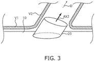
- the branching portion is formed perpendicular to the graft main body regardless of the extending direction of the branched blood vessel, whereas in this embodiment, the branching portion 20 is formed inclinedly with respect to the graft main body 10 depending on an extending direction D of the branched blood vessel V2.
- each of the three branching portions 21 to 23 is situated on the basis of the relative positional relationship between the corresponding branched blood vessel V2 and main blood vessel V1.
- the relative arrangement between the graft main body 10 and the branching portion 20 is defined on the basis of the relative positional relationship between the main blood vessel V1 and the branched blood vessel V2.
- a connection position and a protruding direction AX2 of the branching portion 20 with respect to the graft main body 10 coincide with the connection position and the extending direction D of the branched blood vessel V2 with respect to the main blood vessel V1 (see FIG. 3 ).
- the relative positional relationship between the main blood vessel V1 and the branched blood vessel V2 can be acquired for each patient by a preoperative examination such as computed tomography (CT).
- CT computed tomography
- the protruding direction AX2 of the branching portion 20 is defined by a normal direction of an opening end face of the branching portion 20 (angle between the axial direction AX1 of the graft main body 10 and a normal line). That means, when the protruding direction AX2 of the branching portion 20 with respect to the graft main body 10 coincides with the extending direction D of the branched blood vessel V2, the protruding direction AX2 of the branching portion 20 does not intersect the branched blood vessel V2 in the vicinity of the opening end face of the branching portion 20.
- the branching portion 20 has e.g. an obliquely-cut cylindrical shape obtained by obliquely cutting a cylindrical body as illustrated in FIG. 3 .
- a connection face between the branching portion 20 and the graft main body 10 is elliptic.
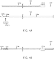
- FIG. 4A and FIG. 4B are diagrams illustrating a configuration of a stent graft placement system 100 (intravascular indwelling system) for placing the stent graft in the blood vessel.
- the first stent graft 1 and the second stent graft 2 can be placed in the blood vessel by using the stent graft placement system 100.
- FIG. 4A illustrates a state that the stent graft placement system 100 is disassembled.
- FIG. 4B illustrates a state that the stent graft placement system 100 is assembled.
- the stent graft placement system 100 includes a tubular sheath 101, an inner rod 102 that is situated inside the sheath 101 and configured to be able to advance and retreat along an axial direction of the sheath 101 (longitudinal direction) in the sheath 101, and a stent graft 103 (first stent graft 1, second stent graft 2).
- the sheath 101 includes a tubular sheath main body part 101a, and a hub 101b disposed on a base end side (proximal end side) of the sheath main body part 101a.
- the hub 101b has a nut for fixing the inner rod 102 to the sheath 101 or releasing the fixation.
- the sheath 101 is made of a flexible material.
- the flexible material include a biocompatible synthetic resin (elastomer) selected from a fluororesin, a polyamide-based resin, a polyethylene-based resin, and a polyvinyl chloride-based resin, and the like, a resin compound obtained by blending other materials into these resins, a multi-layered structure made of these synthetic resins, a complex of these synthetic resins and a metal wire, and the like.
- the inner rod 102 has a bar-like rod main body part 102a, a holding part 102b for holding the stent graft 103 in a contracted state, and a distal end tip 102c disposed on a distal end part (distant end part) of the inner rod 102.
- a diameter of the holding part 102b is set to be smaller than of the rod main body part 102a e.g. by only a thickness of the stent graft 103.
- Examples of materials constituting the rod main body part 102a and the holding part 102b include various materials having appropriate hardness and flexibility, such as a resin (plastic, elastomer) and a metal.
- Examples of a material constituting the distal end tip 102c include various materials having appropriate hardness and flexibility, such as a synthetic resin (elastomer) selected from a polyamide-based resin, a polyurethane-based resin, a polyvinyl chloride-based resin, and the like.
- a lumen through which a guide wire is passed e.g. a lumen through which a trigger wire for expanding the stent graft 103 in a contracted state at a lesion is passed, or the like is formed along an axial direction of the inner rod 102.
- the first stent graft 1 is an intravascular placement tool placed in the blood vessel branching portion on the main blood vessel V1 (first blood vessel) where the branched blood vessel V2 (second blood vessel) branches.
- the first stent graft 1 includes the tubular graft main body 10 (placement tool main body), and the branching portion 20 that is configured to be connectable to the second stent graft 2 (another intravascular placement tool) placed in the branched blood vessel V2 and is formed protrudingly from the graft main body 10.
- the relative arrangement between the graft main body 10 and the branching portion 20 is defined on the basis of the relative positional relationship between the main blood vessel V1 and the branched blood vessel V2.
- the branching portion 20 is formed depending on the extending direction D of the branched blood vessel V2, when the guide wire W for transporting the second stent graft 2 is inserted into the branched blood vessel V2 through the branching portion 20 of the first stent graft 1, the distal end of the guide wire W hardly collides with the blood vessel wall of the branched blood vessel V2 (see FIG. 5A and FIG. 5B ). Thereby, the guide wire W does not deviate into an area other than the branched blood vessel V2, and the second stent graft 2 can be smoothly transported to the branched blood vessel V2.
- the guide wire for transporting the second stent graft 2 can be properly inserted, because the relative arrangement of the branching portion 20 with respect to the curved graft main body 10 is defined on the basis of the relative positional relationship between the curved part of the main blood vessel V1 and the branched blood vessel V2.
- first stent graft 1 and the second stent graft 2 need not be self-expandable, and may be configured to be expanded by an expansion means such as a balloon.
- the branching portion 20 of the first stent graft 1 may have a tapered shape whose diameter decreases toward the opening end part of the through-hole 20a. This makes it possible to improve adhesiveness between the first stent graft 1 and the second stent graft 2.
- the configuration that the plurality of second blood vessels V2 are connected to the first blood vessel V1 in the axial direction has been described as an example, but this configuration is merely an example, and the present invention is not limited to this configuration.
- a relative arrangement between the placement tool main body and two or more branching portions corresponding to each branched blood vessel may be defined on the basis of the relative positional relationship of each branched blood vessel with respect to the main blood vessel.
- the present invention has been explained with reference to the stent graft for thoracic aorta, but the present invention is not limited to this case.
- the present invention can also be applied to stent grafts for abdominal aorta and thoracoabdominal aorta.
- the present invention may also be applied to a stent graft intended to be placed on an organ other than blood vessels (e.g. digestive tract, bile duct, or the like).
- an organ other than blood vessels e.g. digestive tract, bile duct, or the like.
Landscapes
- Health & Medical Sciences (AREA)
- Engineering & Computer Science (AREA)
- Biomedical Technology (AREA)
- Heart & Thoracic Surgery (AREA)
- Public Health (AREA)
- Transplantation (AREA)
- Cardiology (AREA)
- Veterinary Medicine (AREA)
- Oral & Maxillofacial Surgery (AREA)
- Vascular Medicine (AREA)
- Life Sciences & Earth Sciences (AREA)
- Animal Behavior & Ethology (AREA)
- General Health & Medical Sciences (AREA)
- Gastroenterology & Hepatology (AREA)
- Pulmonology (AREA)
- Prostheses (AREA)
- Media Introduction/Drainage Providing Device (AREA)
Applications Claiming Priority (2)
| Application Number | Priority Date | Filing Date | Title |
|---|---|---|---|
| JP2018003349 | 2018-01-12 | ||
| PCT/JP2019/000521 WO2019139077A1 (ja) | 2018-01-12 | 2019-01-10 | 血管内留置具及び血管内留置システム |
Publications (2)
| Publication Number | Publication Date |
|---|---|
| EP3738548A1 true EP3738548A1 (de) | 2020-11-18 |
| EP3738548A4 EP3738548A4 (de) | 2021-09-22 |
Family
ID=67219631
Family Applications (1)
| Application Number | Title | Priority Date | Filing Date |
|---|---|---|---|
| EP19738428.2A Withdrawn EP3738548A4 (de) | 2018-01-12 | 2019-01-10 | Intravaskuläres platzierungswerkzeug und intravaskuläres platzierungssystem |
Country Status (4)
| Country | Link |
|---|---|
| US (1) | US20200368052A1 (de) |
| EP (1) | EP3738548A4 (de) |
| JP (1) | JPWO2019139077A1 (de) |
| WO (1) | WO2019139077A1 (de) |
Families Citing this family (1)
| Publication number | Priority date | Publication date | Assignee | Title |
|---|---|---|---|---|
| CN112022429A (zh) * | 2020-09-27 | 2020-12-04 | 北京裕恒佳科技有限公司 | 分支人工血管修复系统 |
Family Cites Families (8)
| Publication number | Priority date | Publication date | Assignee | Title |
|---|---|---|---|---|
| US7144421B2 (en) * | 2003-11-06 | 2006-12-05 | Carpenter Judith T | Endovascular prosthesis, system and method |
| US7771465B2 (en) | 2006-06-23 | 2010-08-10 | Gore Enterprise Holdings, Inc. | Branched stent delivery system |
| US8715336B2 (en) * | 2007-04-19 | 2014-05-06 | Medtronic Vascular, Inc. | Methods and apparatus for treatment of aneurysms adjacent to branch arteries |
| US9662196B2 (en) * | 2011-09-27 | 2017-05-30 | Cook Medical Technologies Llc | Endoluminal prosthesis with steerable branch |
| US9095421B2 (en) * | 2012-04-18 | 2015-08-04 | Medtronic Vascular, Inc. | Multi-leaflet coupling for branch vessel connection |
| DE102012111225A1 (de) * | 2012-11-21 | 2014-05-22 | Jotec Gmbh | Gefäßimplantat mit Seitenast |
| CN109561958B (zh) * | 2016-05-26 | 2021-03-12 | 瑞士资本工程公司 | 血管医疗装置和系统 |
| JP2018003349A (ja) | 2016-06-29 | 2018-01-11 | ヒロセ株式会社 | 吊り込み式の足場装置およびそれを用いた工事用桟橋の架設方法 |
-
2019
- 2019-01-10 US US16/959,434 patent/US20200368052A1/en not_active Abandoned
- 2019-01-10 JP JP2019564735A patent/JPWO2019139077A1/ja active Pending
- 2019-01-10 WO PCT/JP2019/000521 patent/WO2019139077A1/ja not_active Ceased
- 2019-01-10 EP EP19738428.2A patent/EP3738548A4/de not_active Withdrawn
Also Published As
| Publication number | Publication date |
|---|---|
| JPWO2019139077A1 (ja) | 2021-01-14 |
| EP3738548A4 (de) | 2021-09-22 |
| US20200368052A1 (en) | 2020-11-26 |
| WO2019139077A1 (ja) | 2019-07-18 |
Similar Documents
| Publication | Publication Date | Title |
|---|---|---|
| EP2702964B1 (de) | Stent | |
| JP2018051259A (ja) | ステントグラフト、ステントグラフトセット、及び、ステントグラフト留置装置 | |
| JP7451841B2 (ja) | 管状治療具、管状治療具セット及び管状治療具留置装置 | |
| JP2005525909A (ja) | 分節移植片組込式ステント | |
| EP3811899B1 (de) | Stent für bypass zwischen hohlorganen und stenteinführsystem mit stent für bypass zwischen hohlorganen | |
| US11382735B2 (en) | Stent graft and stent graft indwelling device | |
| KR102668695B1 (ko) | 의료용 관상체 반송 장치 | |
| JP7434683B2 (ja) | ステントグラフト | |
| EP3738548A1 (de) | Intravaskuläres platzierungswerkzeug und intravaskuläres platzierungssystem | |
| JP6770875B2 (ja) | ステントグラフト、ステントグラフトセット、及び、ステントグラフト留置装置 | |
| US20240139008A1 (en) | Catheter and delivery system | |
| US20200330212A1 (en) | Tubular implanted appliance and device for implanting tubular implanted appliance | |
| JP2021013405A (ja) | 血管内留置具接続構造及び血管内留置システム | |
| CN113556992A (zh) | 医疗用管状体输送装置 | |
| JP6035033B2 (ja) | ステント拡張用バルーン、バルーンカテーテルおよびステントデリバリーシステム | |
| JP2019170520A (ja) | ステントデリバリー装置 | |
| CN108430397A (zh) | 治疗装置 | |
| JP7329042B2 (ja) | 医療用管状体搬送装置 | |
| CN116269964A (zh) | 用于输送心血管装置的输送系统 | |
| WO2023176909A1 (ja) | 留置装置 | |
| JP2012192018A (ja) | ステントグラフトデリバリー装置 | |
| CN116322579A (zh) | 医疗用管状体运送装置 | |
| JP2020044292A (ja) | 消化管ステント |
Legal Events
| Date | Code | Title | Description |
|---|---|---|---|
| STAA | Information on the status of an ep patent application or granted ep patent |
Free format text: STATUS: THE INTERNATIONAL PUBLICATION HAS BEEN MADE |
|
| PUAI | Public reference made under article 153(3) epc to a published international application that has entered the european phase |
Free format text: ORIGINAL CODE: 0009012 |
|
| STAA | Information on the status of an ep patent application or granted ep patent |
Free format text: STATUS: REQUEST FOR EXAMINATION WAS MADE |
|
| 17P | Request for examination filed |
Effective date: 20200629 |
|
| AK | Designated contracting states |
Kind code of ref document: A1 Designated state(s): AL AT BE BG CH CY CZ DE DK EE ES FI FR GB GR HR HU IE IS IT LI LT LU LV MC MK MT NL NO PL PT RO RS SE SI SK SM TR |
|
| AX | Request for extension of the european patent |
Extension state: BA ME |
|
| RAP1 | Party data changed (applicant data changed or rights of an application transferred) |
Owner name: KAWASUMI LABORATORIES, INC. |
|
| RIN1 | Information on inventor provided before grant (corrected) |
Inventor name: YUBA, TOSHIYASU Inventor name: HIDARI, KENTARO |
|
| DAV | Request for validation of the european patent (deleted) | ||
| DAX | Request for extension of the european patent (deleted) | ||
| A4 | Supplementary search report drawn up and despatched |
Effective date: 20210819 |
|
| RIC1 | Information provided on ipc code assigned before grant |
Ipc: A61F 2/954 20130101ALN20210813BHEP Ipc: A61F 2/06 20130101ALN20210813BHEP Ipc: A61F 2/89 20130101ALN20210813BHEP Ipc: A61F 2/07 20130101AFI20210813BHEP |
|
| STAA | Information on the status of an ep patent application or granted ep patent |
Free format text: STATUS: THE APPLICATION IS DEEMED TO BE WITHDRAWN |
|
| 18D | Application deemed to be withdrawn |
Effective date: 20220318 |