EP3738559A1 - Système de traitement oculaire par traitement de tissu par interaction non linéaire - Google Patents
Système de traitement oculaire par traitement de tissu par interaction non linéaire Download PDFInfo
- Publication number
- EP3738559A1 EP3738559A1 EP20184228.3A EP20184228A EP3738559A1 EP 3738559 A1 EP3738559 A1 EP 3738559A1 EP 20184228 A EP20184228 A EP 20184228A EP 3738559 A1 EP3738559 A1 EP 3738559A1
- Authority
- EP
- European Patent Office
- Prior art keywords
- short
- wavelength
- radiation
- scanner
- input beam
- Prior art date
- Legal status (The legal status is an assumption and is not a legal conclusion. Google has not performed a legal analysis and makes no representation as to the accuracy of the status listed.)
- Granted
Links
Images


Classifications
-
- A—HUMAN NECESSITIES
- A61—MEDICAL OR VETERINARY SCIENCE; HYGIENE
- A61F—FILTERS IMPLANTABLE INTO BLOOD VESSELS; PROSTHESES; DEVICES PROVIDING PATENCY TO, OR PREVENTING COLLAPSING OF, TUBULAR STRUCTURES OF THE BODY, e.g. STENTS; ORTHOPAEDIC, NURSING OR CONTRACEPTIVE DEVICES; FOMENTATION; TREATMENT OR PROTECTION OF EYES OR EARS; BANDAGES, DRESSINGS OR ABSORBENT PADS; FIRST-AID KITS
- A61F9/00—Methods or devices for treatment of the eyes; Devices for putting in contact-lenses; Devices to correct squinting; Apparatus to guide the blind; Protective devices for the eyes, carried on the body or in the hand
- A61F9/007—Methods or devices for eye surgery
- A61F9/008—Methods or devices for eye surgery using laser
- A61F9/00825—Methods or devices for eye surgery using laser for photodisruption
-
- A—HUMAN NECESSITIES
- A61—MEDICAL OR VETERINARY SCIENCE; HYGIENE
- A61B—DIAGNOSIS; SURGERY; IDENTIFICATION
- A61B3/00—Apparatus for testing the eyes; Instruments for examining the eyes
- A61B3/10—Objective types, i.e. instruments for examining the eyes independent of the patients' perceptions or reactions
-
- A—HUMAN NECESSITIES
- A61—MEDICAL OR VETERINARY SCIENCE; HYGIENE
- A61F—FILTERS IMPLANTABLE INTO BLOOD VESSELS; PROSTHESES; DEVICES PROVIDING PATENCY TO, OR PREVENTING COLLAPSING OF, TUBULAR STRUCTURES OF THE BODY, e.g. STENTS; ORTHOPAEDIC, NURSING OR CONTRACEPTIVE DEVICES; FOMENTATION; TREATMENT OR PROTECTION OF EYES OR EARS; BANDAGES, DRESSINGS OR ABSORBENT PADS; FIRST-AID KITS
- A61F9/00—Methods or devices for treatment of the eyes; Devices for putting in contact-lenses; Devices to correct squinting; Apparatus to guide the blind; Protective devices for the eyes, carried on the body or in the hand
- A61F9/007—Methods or devices for eye surgery
- A61F9/008—Methods or devices for eye surgery using laser
-
- A—HUMAN NECESSITIES
- A61—MEDICAL OR VETERINARY SCIENCE; HYGIENE
- A61F—FILTERS IMPLANTABLE INTO BLOOD VESSELS; PROSTHESES; DEVICES PROVIDING PATENCY TO, OR PREVENTING COLLAPSING OF, TUBULAR STRUCTURES OF THE BODY, e.g. STENTS; ORTHOPAEDIC, NURSING OR CONTRACEPTIVE DEVICES; FOMENTATION; TREATMENT OR PROTECTION OF EYES OR EARS; BANDAGES, DRESSINGS OR ABSORBENT PADS; FIRST-AID KITS
- A61F9/00—Methods or devices for treatment of the eyes; Devices for putting in contact-lenses; Devices to correct squinting; Apparatus to guide the blind; Protective devices for the eyes, carried on the body or in the hand
- A61F9/007—Methods or devices for eye surgery
- A61F9/008—Methods or devices for eye surgery using laser
- A61F2009/00861—Methods or devices for eye surgery using laser adapted for treatment at a particular location
- A61F2009/0087—Lens
-
- A—HUMAN NECESSITIES
- A61—MEDICAL OR VETERINARY SCIENCE; HYGIENE
- A61F—FILTERS IMPLANTABLE INTO BLOOD VESSELS; PROSTHESES; DEVICES PROVIDING PATENCY TO, OR PREVENTING COLLAPSING OF, TUBULAR STRUCTURES OF THE BODY, e.g. STENTS; ORTHOPAEDIC, NURSING OR CONTRACEPTIVE DEVICES; FOMENTATION; TREATMENT OR PROTECTION OF EYES OR EARS; BANDAGES, DRESSINGS OR ABSORBENT PADS; FIRST-AID KITS
- A61F9/00—Methods or devices for treatment of the eyes; Devices for putting in contact-lenses; Devices to correct squinting; Apparatus to guide the blind; Protective devices for the eyes, carried on the body or in the hand
- A61F9/007—Methods or devices for eye surgery
- A61F9/008—Methods or devices for eye surgery using laser
- A61F2009/00861—Methods or devices for eye surgery using laser adapted for treatment at a particular location
- A61F2009/00872—Cornea
-
- A—HUMAN NECESSITIES
- A61—MEDICAL OR VETERINARY SCIENCE; HYGIENE
- A61F—FILTERS IMPLANTABLE INTO BLOOD VESSELS; PROSTHESES; DEVICES PROVIDING PATENCY TO, OR PREVENTING COLLAPSING OF, TUBULAR STRUCTURES OF THE BODY, e.g. STENTS; ORTHOPAEDIC, NURSING OR CONTRACEPTIVE DEVICES; FOMENTATION; TREATMENT OR PROTECTION OF EYES OR EARS; BANDAGES, DRESSINGS OR ABSORBENT PADS; FIRST-AID KITS
- A61F9/00—Methods or devices for treatment of the eyes; Devices for putting in contact-lenses; Devices to correct squinting; Apparatus to guide the blind; Protective devices for the eyes, carried on the body or in the hand
- A61F9/007—Methods or devices for eye surgery
- A61F9/008—Methods or devices for eye surgery using laser
- A61F2009/00885—Methods or devices for eye surgery using laser for treating a particular disease
- A61F2009/00887—Cataract
-
- A—HUMAN NECESSITIES
- A61—MEDICAL OR VETERINARY SCIENCE; HYGIENE
- A61F—FILTERS IMPLANTABLE INTO BLOOD VESSELS; PROSTHESES; DEVICES PROVIDING PATENCY TO, OR PREVENTING COLLAPSING OF, TUBULAR STRUCTURES OF THE BODY, e.g. STENTS; ORTHOPAEDIC, NURSING OR CONTRACEPTIVE DEVICES; FOMENTATION; TREATMENT OR PROTECTION OF EYES OR EARS; BANDAGES, DRESSINGS OR ABSORBENT PADS; FIRST-AID KITS
- A61F9/00—Methods or devices for treatment of the eyes; Devices for putting in contact-lenses; Devices to correct squinting; Apparatus to guide the blind; Protective devices for the eyes, carried on the body or in the hand
- A61F9/007—Methods or devices for eye surgery
- A61F9/008—Methods or devices for eye surgery using laser
- A61F2009/00885—Methods or devices for eye surgery using laser for treating a particular disease
- A61F2009/00887—Cataract
- A61F2009/00889—Capsulotomy
-
- A—HUMAN NECESSITIES
- A61—MEDICAL OR VETERINARY SCIENCE; HYGIENE
- A61F—FILTERS IMPLANTABLE INTO BLOOD VESSELS; PROSTHESES; DEVICES PROVIDING PATENCY TO, OR PREVENTING COLLAPSING OF, TUBULAR STRUCTURES OF THE BODY, e.g. STENTS; ORTHOPAEDIC, NURSING OR CONTRACEPTIVE DEVICES; FOMENTATION; TREATMENT OR PROTECTION OF EYES OR EARS; BANDAGES, DRESSINGS OR ABSORBENT PADS; FIRST-AID KITS
- A61F9/00—Methods or devices for treatment of the eyes; Devices for putting in contact-lenses; Devices to correct squinting; Apparatus to guide the blind; Protective devices for the eyes, carried on the body or in the hand
- A61F9/007—Methods or devices for eye surgery
- A61F9/008—Methods or devices for eye surgery using laser
- A61F2009/00897—Scanning mechanisms or algorithms
Definitions
- the invention relates to a system for eye therapy by processing tissue through non-linear interaction with therapy radiation, the system comprising: a laser device that provides the therapy radiation, a focusing device that has an image field located in a therapy volume, and the therapy radiation such for a focus in the image field that the processing can be generated by non-linear interaction within the tissue, an xy scanner device upstream of the focusing device for lateral displacement of the focus in the image field, a z scanner device that adjusts a depth of the focus in the therapy volume, and a Control device which controls the xy scanner and the z scanner.
- Examples of the use of systems for eye therapy are laser-assisted refractive eye surgery or laser-assisted cataract surgery.
- refractive eye surgery laser radiation is used to create cut surfaces within the cornea that isolate a volume and make it removable. The volume is dimensioned so that its removal changes the corneal curvature in a way that compensates for a previously existing ametropia.
- cataract surgery the natural, opaque eye lens is replaced by an artificial intraocular lens (IOL).
- IOL intraocular lens
- a hole is cut in the capsular bag of the eye lens on its front side. The lens is removed through this hole after fragmentation and an artificial intraocular lens (IOL) is inserted.
- IOL intraocular lens
- an incision is made in the cornea and / or sclera.
- cataract cataract
- short-pulse lasers are used to "cut" eye tissue, for example by means of photodisruption.
- the laser radiation In order to achieve a processing effect with laser radiation within a tissue, the laser radiation must also develop its interaction inside the tissue. In ophthalmology, therefore, laser radiation is used, for which the tissue is actually transparent, and an energy density is generated in a spatially very limited focus that triggers a processing effect. Often an optical breakthrough occurs, which is also referred to in the literature as photodisruption. Short-pulse laser radiation, which is bundled onto a narrow focus, is usually used. The focus size is an essential parameter. This also applies to the depth and depth of the focus. Both parameters are irrelevant in conventional ablation techniques, since they ablate in layers on the surface of the material, i.e. do not act within the material.
- the focus When treating the eye with focused pulses from a femtosecond laser, the focus must be sharply focused over a certain depth adjustment range. For applications on the cornea of the eye, a focus stroke of between 0.5 and 2 mm must be achieved. When used on both the lens of the eye and the Korea, a focus stroke of up to 15 mm is required.
- the fs pulses widening when passing through the optics and the power density in the focus volume required for the application is not achieved.
- the main wavelength is 405 nm and the wavelength range is from 400 nm to 410 nm.
- the classic achromatization of a system at two wavelengths - for example at the secondary wavelengths of 400 nm and 410 nm - leads to wavelengths outside this spectral range ( So for example at 1030 nm to 1050 nm) to strong residual errors.
- These residual defects stem from the characteristic dispersion of the technically available glasses.
- the invention is therefore based on the object of designing a system of the type mentioned at the outset in such a way that, with two comparatively widely spaced focal point wavelengths, processing by non-linear interaction within a tissue is possible.
- the invention is defined in claim 1.
- the system is designed for eye therapy, with tissue being processed by non-linear interaction with therapy radiation.
- a laser device provides therapy radiation.
- a focusing device has an image field located in a therapy volume and bundles the therapy radiation into a focus in the image field. The focus and the laser device are designed in such a way that processing takes place within the tissue by non-linear interaction.
- An xy scanner device is arranged upstream of the focusing device. It shifts the focus laterally in the image field.
- the system also has a z-scanner device that adjusts the depth of the focus in the therapy volume.
- the xy scanner and z scanner are controlled by a control device.
- the laser device provides the therapy radiation.
- a first short-pulse radiation is at a first focal point wavelength.
- a second short-pulse radiation is at a second focal point wavelength that is spaced from the first focal point wavelength by at least 300 nm, preferably 500 nm. Due to the pulse length, in particular in the pulse length range between 1 ps and 1 fs, the two short pulse radiations cover a wavelength range that includes the respective centroid wavelength.
- the system has at least two operating modes. In a first operating mode it works with the first short pulse radiation, in a second operating mode with the second short pulse radiation. With regard to longitudinal and lateral chromatic aberrations, it is designed such that the system has a longitudinal chromatic aberration at at least one of the two centroid wavelengths. A spectral characteristic of the longitudinal chromatic aberration in the first and second wavelength ranges runs essentially horizontally.
- the system is further designed in such a way that the focusing device exhibits a lateral chromatic aberration at at least one of the two centroid wavelengths.
- a spectral characteristic of the lateral chromatic aberration is constant in both wavelength ranges within the framework of a lateral chromatic aberration tolerance. The characteristic curve therefore essentially shows a horizontal profile in the wavelength ranges.
- the control device is designed to control the xy scanner device in such a way that the lateral color error is compensated for by a corresponding deflection function for the lateral displacement of the focus.
- the therapy radiation is then examination radiation or measurement radiation, and the therapy volume is an examination volume.
- the investigation can be carried out by means of non-linear interaction, for example multi-photon processes. But this is not mandatory.
- the only decisive factor for such a modification of the system is that the short pulse nature of the radiation, in particular in the pulse length range between 1 ps and 1 fs, results in wavelength ranges for the first and second short pulse radiation within which the longitudinal and lateral chromatic aberrations are constant within the scope of the tolerances described are.
- the laser device In the system for eye therapy by processing tissue by means of non-linear interaction with therapy radiation, the laser device is provided, which provides the therapy radiation.
- the therapy radiation is bundled by the focusing device in the image field, and the xy scanner and z scanner shift the focus laterally and in depth in a therapy volume. Due to the short pulse properties, the therapy radiation has wavelength ranges.
- the system has been specially corrected with regard to longitudinal and lateral chromatic aberrations, so that the spectral characteristics of both errors in the wavelength ranges each have a local extreme, whereby a certain tolerance is not exceeded in the wavelength ranges, so the characteristics are very flat.
- the longitudinal chromatic aberration or its spectral characteristic describes the axial variation of the focus position as a function of the wavelength.
- the longitudinal chromatic aberration is specified in relation to the axial focus position of a reference wavelength, for example - but not necessarily - in relation to the first or the second centroid wavelength.
- the longitudinal chromatic aberration of the reference wavelength is then by definition equal to zero; the characteristic has a zero point.
- the system has a longitudinal color error in at least one of the centroid wavelengths. If one of the two centroid wavelengths is used as the reference wavelength for the longitudinal chromatic aberration, this is present at the other of the two centroid wavelengths. If neither of the two centroid wavelengths is the reference wavelength for the longitudinal chromatic aberration, the system has a longitudinal chromatic aberration at both centroid wavelengths.
- the constancy of the characteristic within the longitudinal color error tolerance has the consequence that the system has no longitudinal color error within the first wavelength range if one selects a wavelength from this wavelength range as the reference wavelength, e.g. B. the first centroid wavelength.
- the lateral chromatic aberration or its spectral characteristic describes the lateral variation of the focus position transversely to the optical axis or to the direction of light propagation as a function of the wavelength.
- the lateral chromatic aberration is specified in relation to the lateral focus position of a reference wavelength, for example - but not necessarily - in relation to the first or the second focal point wavelength.
- the longitudinal chromatic aberration of the reference wavelength is then by definition equal to zero; the characteristic has a zero point.
- the system has a lateral chromatic aberration in at least one of the centroid wavelengths. If one of the two centroid wavelengths is used as the reference wavelength for the lateral chromatic aberration, this is present at the other of the two centroid wavelengths. If neither of the two centroid wavelengths is the reference wavelength for the lateral chromatic aberration, that has System has a lateral chromatic aberration at both centroid wavelengths.
- the constancy of the characteristic within the lateral chromatic aberration tolerance means that the system has no lateral chromatic aberration within the first wavelength range if one selects a wavelength from this wavelength range as the reference wavelength, e.g. B. the first centroid wavelength. The same applies to the second wavelength range if one selects a wavelength from this wavelength range as the reference wavelength.
- the error tolerances allow the corresponding longitudinal or lateral chromatic aberrations to fluctuate slightly within the specified wavelength ranges; in the case of the longitudinal chromatic aberration, the volume covered by the focus of the short-pulse radiation is widened axially, in the case of the lateral chromatic aberration, it is widened laterally.
- the term “slightly” is based on the fact that the expansion does not destroy the conditions for the effect of the short-pulse radiation, that is to say for generating the non-linear interaction or the desired quality of observation.
- the longitudinal color error tolerance is dimensioned in such a way that the axial expansion of the focus volume for the affected short-pulse radiation remains limited to an extent that the generation of the non-linear interaction is not impaired or not impaired.
- the longitudinal color error tolerance is e.g. B. a certain multiple of the depth of field, for example 0.1 x, 0.2 x, 0.5 x, 1 x or 2 x the depth of field of the focusing device.
- the lateral color error tolerance is a certain multiple of the lateral focus size, based on the so-called Airy diameter, for example 0.1 x, 0.2 x, 0.5 x, 1 x or 2 x the Airy diameter.
- Airy diameter for example 0.1 x, 0.2 x, 0.5 x, 1 x or 2 x the Airy diameter.
- the constancy of lateral chromatic aberrations and longitudinal chromatic aberrations within the corresponding tolerance ensures that the wavelength ranges in the system, and in particular by the focusing device, are guided in such a way that their width does not lead to an expansion of the focus volume that would be so large that non-linear interaction is no longer achieved or this is no longer achieved to a sufficient extent or the quality of observation would be lacking.
- the system can dispense with apochromatization of the optics.
- the remaining (albeit constant) lateral color error at at least one of the focal wavelengths leads to a deflection angle controlled at the xy scanner device resulting in an additional or reduced lateral deflection due to the lateral color error experiences in the therapy volume.
- the control device ensures that this lateral shift of the focus is compensated for by a corresponding activation of the xy scanner device. A complex correction is therefore surprisingly easily replaced by a corresponding control of the xy scanner device.
- the longitudinal chromatic aberration that exists between the second and the first focal wavelength can also be compensated by the control device by controlling the z-scanner device in such a way that the depth of the focus is compensated by a corresponding offset when operating with the short pulse radiation affected by the longitudinal chromatic aberration. Due to the required constancy of the spectral characteristic curve of the longitudinal chromatic aberration, the longitudinal chromatic aberration expresses itself exclusively through an offset of the depth position of the focus without causing an impermissible axial focus deformation over the first wavelength range.
- a refocusing element which only acts on the affected short-pulse radiation or is only activated, which partially or completely compensates for the longitudinal color error by means of a corresponding offset of the depth of the focus.
- the alternating operation of the system with the two short-pulse radiation i.e. the operating modes mentioned at the beginning, can be implemented with little effort in embodiments in that the system has a first input beam path for the first short-pulse radiation and a second input radiation path for the second short-pulse radiation and also a combining device upstream of the focusing device which merges the two input beam paths or switches between these two.
- the system has a first input beam path for the first short-pulse radiation and a second input radiation path for the second short-pulse radiation and also a combining device upstream of the focusing device which merges the two input beam paths or switches between these two.
- a correction element activated by the control device which can be activated with regard to a correction effect for the second wavelength range.
- an active correction effect modifies the optics in such a way that the spectral characteristic curve of the longitudinal color error, which is constant within the framework of the longitudinal color error tolerance, is given in the second wavelength range.
- the control device activates the correction element with regard to its corrective effect only when the second short-pulse radiation passes through the system. It deactivates the correction element with regard to its corrective effect when the first short-pulse radiation passes through the system, since the The system has already been corrected for this.
- Optics that have already been optimally color-corrected for the first short-pulse radiation can thus be expanded with little effort for operation with the second short-pulse radiation, namely by the mentioned correction element.
- the correction element in a pupil of the focusing optics, preferably to pivot it in there. It can also be designed as an adjustable optical element, in particular as a vario lens or MEMS array, which is activated or deactivated by the control device with regard to its corrective effect by setting the optical element accordingly.
- the combining device can also be designed in such a way that it contains a correction element of the properties mentioned, which only acts on the second short-pulse radiation.
- an embodiment with the two input beam paths is particularly preferred in which the first input beam path or the focusing device has the correction with regard to the constant spectral characteristic curve of the longitudinal chromatic aberration in the first wavelength range and the correction element, which effects the characteristic curve adaptation of the longitudinal chromatic aberration for the second wavelength range, is provided in the second input beam path.
- This embodiment allows, in particular, the z-scanner device to be designed in one piece, with a second z-scanner for the second short-pulse radiation in the second input beam path and a first z-scanner for the first short-pulse radiation in the first input beam path.
- the correction element can then be arranged directly in the second z-scanner, in particular in a fixed optical element of a telescope which implements the second z-scanner in the form of a movable and a fixed optical element.
- the function of the correction element is implemented in the aforementioned refocusing element.
- the focusing device is also corrected for one of the two wavelength ranges with regard to monochromatic errors.
- the other wavelength range it has a monochromatic residual error and in a beam path through which only the radiation of this wavelength range passes, there is a compensating optical system that compensates for the monochromatic residual error.
- Compensating optics and correction element and optionally also refocusing element can be combined in one correction optics element in preferred embodiments.
- the focal point wavelength is preferably not more than 420 nm, more preferably between 380 and 420 nm, particularly preferably 405 nm.
- the other focal point wavelength is preferably not less than 730 nm, more preferably between 1030 and 1060 nm, particularly preferably 1040 nm. Either of the two can be the first or second centroid wavelength.
- the two wavelength ranges are preferably not wider than 30 nm, particularly preferably not wider than 15 nm.
- the z-stroke of the z-scanner device is preferably at least 1 mm for applications on the flattened cornea, more preferably at least 3 mm for applications on the curved cornea, particularly preferably at least 5 mm for work on the eye lens and more particularly preferably at least 13 mm for applications in cataract surgery.
- the z-scanner device comprises a mechanically moved component that executes a comparatively large stroke, it is preferred for ophthalmological applications to arrange such components as far away from the patient as possible. This avoids vibrations and noises that could irritate the patient. It is therefore preferred that the z-scanner device comprises at least one divergence-varying optical element which is arranged upstream of the xy-scanner and which changes the divergence of the therapy radiation in an adjustable manner.
- a configuration with a telescope with a fixed converging lens system and a movable lens system is particularly preferred. In embodiments with two z-scanners, one or both z-scanners can be designed in this way.
- the telescope is expediently designed as a Galileo telescope.
- Scanning systems consist, on the one hand, of optical components that are located in front of the scanning elements in the direction of light. These components are only used axially. After the scanning elements, there are also optical components (focusing device; also referred to as scanning optics), which also map off-axis field bundles towards the image.
- focusing device also referred to as scanning optics
- optical components in front of the scanners include collimators, beam expanders, polarization-optical elements or systems for divergence variation, i.e. for focusing.
- Image errors that are independent of the field that is to say that occur to the same extent both on the optical axis and off the optical axis, can possibly already be caused by elements correct before the scanners. These include, in particular, longitudinal color defects and spherical aberration.
- fs lasers are the short-pulse lasers most frequently used in the field of laser-assisted eye surgery - and therefore also the best-studied. Nevertheless, all of the systems described here can also be implemented with other short-pulse lasers. So unless the pulse length is explicitly discussed as a differentiating feature, fs lasers are synonymous with short pulse lasers.
- the system described here on which the various aspects of the invention are implemented in combination purely by way of example, is used for laser-assisted corneal surgery. Cuts are made in the cornea by means of the short-pulse laser beam source, for example to correct ametropia.
- the system can also be designed for cataract surgery, e.g. to make an access incision to the anterior chamber of the eye through the cornea, a capsulotomy incision, incisions to break up the nucleus of the eye.
- Fig. 1 shows schematically the beam path of a therapy system 1 for ophthalmology, in particular for cornea surgery.
- the therapy system 1 is designed to work at two wavelengths, namely at a first focus wavelength of 405 nm and a second focus wavelength of 1040 nm. The wavelengths are used individually, ie the therapy system 1 is switchable between the two wavelengths.
- a first laser source 3 provides a first laser beam 4 at the first focus wavelength of 405 nm
- a second laser source 5 provides a second laser beam 6 at the second focus wavelength of 1030 nm.
- the laser sources 3, 6 are short-pulse laser sources, so that the laser beams 4, 6 are pulsed laser radiation with a pulse length, for example, in the fs range.
- a z-scanner 7 is provided which is designed to adjust the depth of a focus in the cornea of the eye 2, which is yet to be explained.
- the second laser beam 6 is adjusted in depth with a second z-scanner 8.
- An xy scanner device 9 is also designed as a unifying element for the two beam paths of the second laser beam 6 and the first laser beam 4 and feeds one of the two laser beams scanned into the beam path of a focusing optics 10. The selection between the two beams can be made either by the xy scanner device 9 switches between one of the two beams so that only one of the two beams scanned runs through the focusing optics 10.
- the two beam paths can be continuously combined and only one of the two laser sources 3, 5 is activated.
- This can be adjusted accordingly by a control device S, which controls the entire operation of the therapy system 1 and in particular also controls the laser sources 3, 5, the xy scanner device 9 and the z scanners 7, 8.
- the focusing optics 10 comprise an objective 11 and bundle the first or second laser beam 4, 6 laterally scanned by the xy scanner device 9 through a contact glass 12 into the cornea of the eye 2.
- the two main wavelengths are separated by more than 500 nm.
- the focus in the cornea and the design of the laser sources 3, 5 are designed in such a way that the pulses of the laser beams 4, 6 create an optical breakthrough in the cornea or separate tissue layers in the cornea by means of an uninterrupted, non-linear interaction. In order for this effect to occur, a high focus quality must be achieved.
- the spectral difference between the first and second laser beam 4, 6 would lead to an optical system that is designed exclusively for one of the two wavelengths, that chromatic errors would occur at the other wavelength. The consequence of this would be that a desired focus position would no longer be reached.
- no optical breakthrough or non-linear interaction would be achieved.
- the laser beams Due to the short-pulse properties of the first and second laser radiation 4, 6, the laser beams have a certain bandwidth around the mentioned focus wavelengths, that is to say each cover a wavelength range. Due to physical laws, the width of these wavelength ranges is inextricably linked with the shortness of the laser pulses of the laser beams.
- the therapy system 1 is for the first wavelength, ie for the radiation of the first laser beam 4 and for the radiation of the second laser beam 6 and the second wavelength range determined thereby, corrected in a certain way. This correction is shown below using the Fig. 5 , 6th and 8th will be explained in more detail.
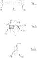
- Fig. 2 shows the z-scanner 7 or 8 by way of example. It is designed as a Galilean telescope with a fixed collecting optics 16 and a movable diverging optics 17. By shifting the movable diverging optics 17, the divergence of the radiation after the z-scanner 7, 8 is adjusted accordingly, which ultimately allows the depth of the focus in the eye 2 to be set together with the focusing optics 10.
- Fig. 3 shows a schematic embodiment for the xy scanner device 9, which has a dichroic combiner 18 which combines the second laser beam 6 and the first laser beam 4 and guides them as a common beam path 19 to a pair of scanner mirrors 20. From there there is a scanned beam path 21 which then runs through the focusing optics 10 and the objective 11 and the contact glass 12.
- an optical correction element 15d is also shown, which can be provided on the dichroic combiner 12 and acts on the second laser beam 6.
- This optical correction element 15d is an alternative to using the optical correction element 15a. Its function will also be explained later.
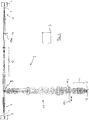
- Fig. 5 shows the spectral profile of the longitudinal chromatic aberration Z of the therapy system 1 in therapy volume, ie in the volume in which the eye 2 comes to rest.
- the characteristic curve 24 shows the longitudinal color error curve over the wavelength ⁇ for a conventional device, which is therefore only designed for one focal wavelength.
- the longitudinal chromatic aberration Z increases from a wavelength of 400 nm.
- the second centroid wavelength 31 which is 1040 nm here
- the first centroid length 31 which is 405 nm here.
- the representation of the Fig. 5 for example of about 1 mm.
- this longitudinal color error is largely constant due to a special correction 28 of the system 1 and remains within a color longitudinal error tolerance 27, which is shown in dashed lines in the enlarged section.
- the enlarged section shows the second wavelength range 26 with the corrected characteristic curve 25 achieved.
- the conventional characteristic curve 24 is drawn in such a way that it intersects the corrected characteristic curve 25. This serves to illustrate the different slope.
- characteristic curve 25 is largely horizontal with respect to the uncorrected characteristic curve 24, so that it remains within the longitudinal color error tolerance 27.
- the characteristic curve 24 does not have this property.
- the optics of the therapy system 1 have been corrected, i.e. in particular the focusing optics 10 and the lens 11.
- the characteristic curve 25 now runs essentially horizontally.
- the correction 28 does not depend on the absolute storage of the longitudinal color error. Rather, a longitudinal color error between the second focal point wavelength 31 and the first focal point wavelength 30 is consciously accepted.
- the longitudinal color error that is present at the second focal point wavelength 31 can be compensated for by a simple refocusing 29. Because of the correction 29, which keeps the characteristic curve 25 constant within the longitudinal color error tolerance 27, the focus volume is not expanded axially in an impermissible manner. The axial focus quality remains so that the non-linear interaction is achieved.
- the characteristic curve 25 of the therapy system 1 can be achieved particularly easily by designing the optics of the therapy system for the first focal wavelength 30, that is to say for 405 nm, with regard to a conventional longitudinal color error correction.
- the second focal point wavelength 31 it then only has to be ensured that the constancy of the characteristic curve 25 is also given in the wavelength range 26 around the second focal point wavelength 31.
- the optical correction element 15a-15d which is exclusively from the second Laser beam 6 is irradiated at the second focal point wavelength 31.
- the design of the therapy system 1 with the optical correction element 15a in the pupil plane 14 and in a section of the beam path before the merging at the xy scanner device 9 is one way of achieving this correction and constancy of the characteristic curve in the wavelength range 26.
- FIG. 3 shows an example of an arrangement of a correction optical element 15d which acts exclusively on the second laser beam 6.
- Fig. 4 shows a possible construction for the correction optical element 15a, b, d, comprising a negative optical element 22 and a positive optical element 23.
- Optical corrections for influencing the longitudinal chromatic aberration characteristic are known in principle to the person skilled in the art.
- the focus position and focus extent is not only influenced by the longitudinal chromatic aberration Z, but also by the lateral chromatic aberration F. This is particularly important in therapy system 1, since it is a scanning therapy system that laterally adjusts the position of a focus in an image field.
- the xy scanner device 9 causes the focusing optics 10 to be irradiated in different positions relative to the optical axis, depending on the lateral focus position. With these shelves, of course, there are chromatic transverse chromatic aberrations.
- Fig. 6 shows the intended correction of the therapy system 1 and in particular of the focusing optics 10.
- the spectral profile of the characteristic curve for the lateral chromatic aberration F is plotted, which is plotted here as a relative lateral chromatic error in ⁇ as an example.
- the lateral chromatic aberration 405 is corrected at the first centroid wavelength 30. It is therefore the reference wavelength. This would also be the case for a conventional characteristic curve 32. The correction is also carried out in such a way that the characteristic curve 33 results, which is essentially constant at the second centroid wavelength 31. It remains within a transverse color error tolerance 35. This would generally not be the case for a correction based on 405 nm alone.
- the focusing optics 10 are specially corrected for this.
- the lateral chromatic aberration present at the second focal point wavelength 31 thus results in a deflection angle modification 34.
- the lateral chromatic aberration can easily be caused by a correspondingly changed control of the xy scanner device 9 be compensated when the therapy system 1 works at the second focal wavelength 31, that is to say with the second laser beam 6. Since the lateral chromatic aberration also remains within the lateral chromatic error tolerance 35 in the second wavelength range, an impermissible expansion of the focus volume in the lateral direction, i.e. transversely to the optical axis, is avoided and in the focus non-linear processing effects are reliably achieved within the tissue. Needless to say, the lateral color error remains within the lateral color error tolerance 35 even with the first centroid wavelength 30. It is z. B. 0.5 ⁇ m absolute.
- the characteristic curve 33 does not require a perfect apochromatization of the focusing optics 10. This would consist in the fact that the lateral chromatic aberration also disappears around the second focal point wavelength 31. Since this requirement is not made, but only the lateral chromatic aberration must remain within the lateral chromatic aberration tolerance both in the second wavelength range, which surrounds the second focal point wavelength 31, and in the first wavelength range, which surrounds the first focal point wavelength 30, the optical correction is simplified.
- Fig. 7 shows the effect on the position of a focus 36 in the cornea 39 of the eye 2.
- the transverse chromatic aberration F has no effect. It only plays a role when the focus 36 is deflected laterally in the cornea 39.
- the two left bundles of rays show the relationships for the second laser beam 6 at the second centroid wavelength 31, the two right bundles of rays for the first laser beam 4 at the first Center of gravity wavelength 30.
- the control device S compensates for this difference by means of a suitable deflection angle modification 36, so that the focus 36 is again at the desired location in the cornea.
- Fig. 7 further shows the importance of refocusing to compensate for the longitudinal chromatic aberration.
- the thickness d of the cornea is 0.5 mm. Without refocusing, the longitudinal color error between the second and first focal point wavelength 31, 30 would have a value of 1 mm. This value would be greater than the thickness d of the cornea 39, so that the focus 36 would undesirably lie entirely outside the cornea 39 at one of the two wavelengths.
- the refocusing 29 prevents this.
- the refocusing 29 can be implemented by a corresponding configuration of the control device S, which provides the control of the z-scanner 7, 8 concerned with an offset in order to effect the refocusing 29 and to compensate for the longitudinal color error.
- a corresponding optical element can be used that changed the axial position. In embodiments, this optical element can be combined with the correction optical element 15a-d or provided therein.
- the Fig. 5 and 6th show relationships in which the longitudinal chromatic aberration or the lateral chromatic aberration is corrected for a wavelength, in the embodiments shown for the first centroid wavelength 30.
- the first focal wavelength is therefore the reference wavelength mentioned at the beginning. However, this is not absolutely necessary.
- Characteristic curves 25, 33 are also possible which have a longitudinal color error Z different from zero and / or lateral color error F at both centroid wavelengths 30, 31, ie a completely different reference wavelength. This is completely harmless as long as the corresponding errors do not exceed the prescribed error tolerance ranges in the corresponding wavelength ranges around the centroid wavelengths 30, 31.
- Fig. 8 shows an exemplary corresponding embodiment with regard to the lateral chromatic aberration F. This is zero here at the second centroid wavelength 31 and different from zero at the first centroid wavelength 30. However, care is again taken to ensure that the lateral color error does not exceed the lateral color error tolerance 35 within the wavelength ranges that are entered here with 37 and 38.
- the correction of the therapy system 1 is basically designed in such a way that both the longitudinal color error and the lateral color error in the wavelength ranges that arise due to the pulse length around the focal wavelengths 30, 31 have local extrema that are so flat that in the Wavelength ranges the corresponding tolerances are not exceeded and the non-linear interaction occurs reliably in the focus.
- the correction is therefore very much simpler than if vanishing longitudinal and lateral chromatic aberrations were required for both centroid wavelengths 30, 31 and within the wavelength ranges surrounding them.
- the setting of the zero value is ultimately a scaling. It is possible for each curve to use the z-value at one of the two centroid wavelengths as a reference plane, i.e. to be defined as the zero plane of the depth of focus specification. Ultimately, from a physical point of view, the longitudinal chromatic aberration is only a change in the focal plane when changing between two wavelengths, here the centroid wavelengths 30, 31.
- every imaging system also has monochromatic errors.
- the therapy system in embodiment c is designed in such a way that the monochromatic errors are compensated for only for one of the two wavelengths for the beam path from the laser source to the eye.
- a compensation element in inserted the part of the beam path that is only penetrated by this wavelength, or a compensating element is swiveled into the common beam path when the other wavelength is active or an adjustable compensating element is activated in the common beam path or set appropriately when the other wavelength is active.
- the compensating element is combined with the optical correction element.
Landscapes
- Health & Medical Sciences (AREA)
- Ophthalmology & Optometry (AREA)
- Life Sciences & Earth Sciences (AREA)
- Surgery (AREA)
- General Health & Medical Sciences (AREA)
- Physics & Mathematics (AREA)
- Engineering & Computer Science (AREA)
- Biomedical Technology (AREA)
- Heart & Thoracic Surgery (AREA)
- Veterinary Medicine (AREA)
- Public Health (AREA)
- Animal Behavior & Ethology (AREA)
- Nuclear Medicine, Radiotherapy & Molecular Imaging (AREA)
- Optics & Photonics (AREA)
- Vascular Medicine (AREA)
- Biophysics (AREA)
- Medical Informatics (AREA)
- Molecular Biology (AREA)
- Mechanical Optical Scanning Systems (AREA)
- Laser Surgery Devices (AREA)
- Eye Examination Apparatus (AREA)
Applications Claiming Priority (4)
| Application Number | Priority Date | Filing Date | Title |
|---|---|---|---|
| DE102016213095 | 2016-07-18 | ||
| DE102017107915.7A DE102017107915A1 (de) | 2016-07-18 | 2017-04-12 | System zur Augentherapie mittels Gewebebearbeitung durch nichtlineare Wechselwirkung |
| PCT/EP2017/068044 WO2018015349A1 (fr) | 2016-07-18 | 2017-07-17 | Système de traitement oculaire par traitement de tissu par interaction non linéaire |
| EP17740017.3A EP3484424B1 (fr) | 2016-07-18 | 2017-07-17 | Système de traitement oculaire par traitement de tissu par interaction non linéaire |
Related Parent Applications (1)
| Application Number | Title | Priority Date | Filing Date |
|---|---|---|---|
| EP17740017.3A Division EP3484424B1 (fr) | 2016-07-18 | 2017-07-17 | Système de traitement oculaire par traitement de tissu par interaction non linéaire |
Publications (3)
| Publication Number | Publication Date |
|---|---|
| EP3738559A1 true EP3738559A1 (fr) | 2020-11-18 |
| EP3738559B1 EP3738559B1 (fr) | 2023-06-28 |
| EP3738559B8 EP3738559B8 (fr) | 2023-08-23 |
Family
ID=60783045
Family Applications (2)
| Application Number | Title | Priority Date | Filing Date |
|---|---|---|---|
| EP17740017.3A Active EP3484424B1 (fr) | 2016-07-18 | 2017-07-17 | Système de traitement oculaire par traitement de tissu par interaction non linéaire |
| EP20184228.3A Active EP3738559B8 (fr) | 2016-07-18 | 2017-07-17 | Système de traitement oculaire par traitement de tissu par interaction non linéaire |
Family Applications Before (1)
| Application Number | Title | Priority Date | Filing Date |
|---|---|---|---|
| EP17740017.3A Active EP3484424B1 (fr) | 2016-07-18 | 2017-07-17 | Système de traitement oculaire par traitement de tissu par interaction non linéaire |
Country Status (6)
| Country | Link |
|---|---|
| US (2) | US11000412B2 (fr) |
| EP (2) | EP3484424B1 (fr) |
| JP (1) | JP7083562B2 (fr) |
| CN (2) | CN113230027B (fr) |
| DE (1) | DE102017107915A1 (fr) |
| WO (1) | WO2018015349A1 (fr) |
Families Citing this family (4)
| Publication number | Priority date | Publication date | Assignee | Title |
|---|---|---|---|---|
| DE102017107915A1 (de) * | 2016-07-18 | 2018-01-18 | Carl Zeiss Meditec Ag | System zur Augentherapie mittels Gewebebearbeitung durch nichtlineare Wechselwirkung |
| JP2024538244A (ja) * | 2021-11-19 | 2024-10-18 | アルコン インコーポレイティド | 眼浮遊物を破砕及び除去するための気泡噴流の発生 |
| EP4201382B1 (fr) * | 2021-12-23 | 2025-10-08 | Ziemer Ophthalmic Systems AG | Dispositif ophtalmologique de traitement d'une face de traitement courbe |
| CN115737118B (zh) * | 2022-12-13 | 2025-06-13 | 深圳市宗匠科技有限公司 | 激光美容模组及激光美容仪 |
Citations (12)
| Publication number | Priority date | Publication date | Assignee | Title |
|---|---|---|---|---|
| US5246435A (en) | 1992-02-25 | 1993-09-21 | Intelligent Surgical Lasers | Method for removing cataractous material |
| US6325792B1 (en) | 1991-11-06 | 2001-12-04 | Casimir A. Swinger | Ophthalmic surgical laser and method |
| WO2003057100A2 (fr) * | 2002-01-10 | 2003-07-17 | Katana Technologies Gmbh | Dispositif et procedure pour chirurgie refractive au laser |
| US20060195076A1 (en) | 2005-01-10 | 2006-08-31 | Blumenkranz Mark S | Method and apparatus for patterned plasma-mediated laser trephination of the lens capsule and three dimensional phaco-segmentation |
| EP1792593A1 (fr) * | 2005-12-01 | 2007-06-06 | Wavelight Laser Technologie AG | Dispositif laser pour le traitement réfractife de l'oeil |
| WO2007124602A1 (fr) * | 2006-05-03 | 2007-11-08 | Campbell Melanie C W | Procédé et dispositif permettant d'administrer une énergie lumineuse localisée dans l'oeil |
| WO2008077532A1 (fr) * | 2006-12-21 | 2008-07-03 | Carl Zeiss Meditec Ag | Agencement d'appareils ophtalmologiques visant à l'amélioration des images d'observation |
| US20090131921A1 (en) | 2007-09-06 | 2009-05-21 | Lensx Lasers, Inc. | Precise Targeting of Surgical Photodisruption |
| DE102008011836A1 (de) * | 2008-02-28 | 2009-09-03 | Carl Zeiss Meditec Ag | Ophthalmologisches Gerät und Verfahren zur Beobachtung, Untersuchung, Diagnose und/oder Therapie eines Auges |
| WO2011059958A2 (fr) * | 2009-11-16 | 2011-05-19 | Alcon Lensx, Inc. | Système optique à étages variables pour laser de chirurgie ophtalmique |
| DE102011085046A1 (de) | 2011-10-21 | 2013-04-25 | Carl Zeiss Meditec Ag | Erzeugung von Schnittflächen in einem transparenten Material mittels optischer Strahlung |
| US20150323774A1 (en) * | 2009-09-24 | 2015-11-12 | Carl Zeiss Microscopy Gmbh | Microscope with a light sheet |
Family Cites Families (30)
| Publication number | Priority date | Publication date | Assignee | Title |
|---|---|---|---|---|
| DE60042812D1 (de) * | 1999-01-22 | 2009-10-08 | Konica Minolta Opto Inc | Optische Abtastvorrichtung, mit der optischen Abtastvorrichtung versehenes Aufnahme/Wiedergabegerät, optisches Element und Verfahren zur Datenaufnahme/wiedergabe |
| ATE399990T1 (de) * | 2001-10-09 | 2008-07-15 | Univ Ruprecht Karls Heidelberg | Fernfeld lichtmikroskopische methode und vorrichtung zur bestimmung von mindestens einem objekt kleiner als die benutzte wellenlänge |
| JP3856691B2 (ja) * | 2001-12-05 | 2006-12-13 | 株式会社トプコン | 観察装置 |
| DE102004034977A1 (de) | 2004-07-16 | 2006-02-02 | Carl Zeiss Jena Gmbh | Lichtrastermikroskop und Verwendung |
| GB0617945D0 (en) * | 2006-09-12 | 2006-10-18 | Ucl Business Plc | Imaging apparatus and methods |
| BRPI0718863B1 (pt) * | 2006-11-10 | 2019-08-27 | Michael Larsen Lars | sistema para fotomanipulação não disruptiva ou minimamente disruptiva do cristalino de um olho animal ou humano |
| DE102007053281A1 (de) * | 2007-11-08 | 2009-05-14 | Carl Zeiss Meditec Ag | Behandlungsvorrichtung zur operativen Fehlsichtigkeitskorrektur eines Auges, Verfahren zum Erzeugen von Steuerdaten dafür und Verfahren zur operativen Fehlsichtigkeitskorrektur eines Auges |
| US10182942B2 (en) * | 2008-06-05 | 2019-01-22 | Carl Zeiss Meditec Ag | Ophthalmological laser system and operating method |
| CN102596126B (zh) * | 2009-07-29 | 2014-08-13 | 爱尔康蓝斯克斯股份有限公司 | 用于眼科手术激光的光学系统 |
| US9504608B2 (en) * | 2009-07-29 | 2016-11-29 | Alcon Lensx, Inc. | Optical system with movable lens for ophthalmic surgical laser |
| MX2012003189A (es) | 2009-12-07 | 2012-04-30 | Wavelight Gmbh | Dispositivo para cirugia laser oftalmologica. |
| US10085886B2 (en) * | 2010-01-08 | 2018-10-02 | Optimedica Corporation | Method and system for modifying eye tissue and intraocular lenses |
| JP5763681B2 (ja) * | 2010-01-22 | 2015-08-12 | オプティメディカ・コーポレイション | 走査レーザによる嚢切開を自動配置する装置 |
| CA2832517C (fr) * | 2010-05-05 | 2021-07-13 | Melanie Crombie Williams CAMPBELL | Procede et systeme d'imagerie de l'amyloide beta de la retine de l'oeil en lien avec la maladie d'alzheimer |
| US9256066B2 (en) * | 2011-03-01 | 2016-02-09 | Ge Healthcare Bio-Sciences Corp. | Laser beam irradiance control systems |
| EP2715453A1 (fr) * | 2011-06-01 | 2014-04-09 | Eulitha A.G. | Imprimer des motifs périodiques au moyen de lasers multiples |
| US10813791B2 (en) * | 2011-06-02 | 2020-10-27 | University Of Rochester | Method for modifying the refractive index of ocular tissues and applications thereof |
| DE102011109058A1 (de) * | 2011-07-29 | 2013-01-31 | Carl Zeiss Meditec Ag | "Ophthalmologische Laservorrichtung und Verfahren zur Prävention und zur Behandlung von Nachstar" |
| DE102012018421A1 (de) * | 2012-09-14 | 2014-03-20 | Carl Zeiss Meditec Ag | Augenchirurgische Refraktionskorrektur |
| US9709789B2 (en) * | 2013-01-31 | 2017-07-18 | Danmarks Tekniske Universitet | Infrared up-conversion microscope |
| EP2951640A1 (fr) * | 2013-01-31 | 2015-12-09 | Danmarks Tekniske Universitet | Télescope d'interpolation infrarouge |
| DE102013101711A1 (de) * | 2013-02-21 | 2014-08-21 | Carl Zeiss Microscopy Gmbh | Objektiv und optisches Beobachtungsgerät |
| US10369053B2 (en) * | 2013-04-17 | 2019-08-06 | Optimedica Corporation | Corneal topography measurements and fiducial mark incisions in laser surgical procedures |
| US9844320B2 (en) * | 2014-01-29 | 2017-12-19 | University Of Rochester | System and method for observing an object in a blood vessel |
| WO2015147925A1 (fr) * | 2014-03-26 | 2015-10-01 | Optimedica Corporation | Système de chirurgie oculaire par laser confocal |
| DE102015201393B4 (de) | 2015-01-28 | 2025-05-08 | Carl Zeiss Microscopy Gmbh | Anordnung zur Fokusveränderung eines Mikroskopobjektivs |
| DE102015203844A1 (de) | 2015-03-04 | 2016-09-08 | Carl Zeiss Meditec Ag | Optiksystem und Operationsmikroskop |
| DE102017107915A1 (de) * | 2016-07-18 | 2018-01-18 | Carl Zeiss Meditec Ag | System zur Augentherapie mittels Gewebebearbeitung durch nichtlineare Wechselwirkung |
| FR3067457A1 (fr) * | 2017-06-13 | 2018-12-14 | Commissariat A L'energie Atomique Et Aux Energies Alternatives | Procede et systeme de controle de la vitesse d'une impulsion laser |
| EP3978964A1 (fr) * | 2020-10-01 | 2022-04-06 | ASML Netherlands B.V. | Agencement de relais optique achromatique |
-
2017
- 2017-04-12 DE DE102017107915.7A patent/DE102017107915A1/de active Pending
- 2017-07-17 CN CN202110498226.9A patent/CN113230027B/zh active Active
- 2017-07-17 EP EP17740017.3A patent/EP3484424B1/fr active Active
- 2017-07-17 WO PCT/EP2017/068044 patent/WO2018015349A1/fr not_active Ceased
- 2017-07-17 JP JP2019501962A patent/JP7083562B2/ja active Active
- 2017-07-17 EP EP20184228.3A patent/EP3738559B8/fr active Active
- 2017-07-17 CN CN201780044048.4A patent/CN109475432B/zh active Active
- 2017-07-17 US US16/318,448 patent/US11000412B2/en active Active
-
2021
- 2021-04-09 US US17/226,890 patent/US11992439B2/en active Active
Patent Citations (12)
| Publication number | Priority date | Publication date | Assignee | Title |
|---|---|---|---|---|
| US6325792B1 (en) | 1991-11-06 | 2001-12-04 | Casimir A. Swinger | Ophthalmic surgical laser and method |
| US5246435A (en) | 1992-02-25 | 1993-09-21 | Intelligent Surgical Lasers | Method for removing cataractous material |
| WO2003057100A2 (fr) * | 2002-01-10 | 2003-07-17 | Katana Technologies Gmbh | Dispositif et procedure pour chirurgie refractive au laser |
| US20060195076A1 (en) | 2005-01-10 | 2006-08-31 | Blumenkranz Mark S | Method and apparatus for patterned plasma-mediated laser trephination of the lens capsule and three dimensional phaco-segmentation |
| EP1792593A1 (fr) * | 2005-12-01 | 2007-06-06 | Wavelight Laser Technologie AG | Dispositif laser pour le traitement réfractife de l'oeil |
| WO2007124602A1 (fr) * | 2006-05-03 | 2007-11-08 | Campbell Melanie C W | Procédé et dispositif permettant d'administrer une énergie lumineuse localisée dans l'oeil |
| WO2008077532A1 (fr) * | 2006-12-21 | 2008-07-03 | Carl Zeiss Meditec Ag | Agencement d'appareils ophtalmologiques visant à l'amélioration des images d'observation |
| US20090131921A1 (en) | 2007-09-06 | 2009-05-21 | Lensx Lasers, Inc. | Precise Targeting of Surgical Photodisruption |
| DE102008011836A1 (de) * | 2008-02-28 | 2009-09-03 | Carl Zeiss Meditec Ag | Ophthalmologisches Gerät und Verfahren zur Beobachtung, Untersuchung, Diagnose und/oder Therapie eines Auges |
| US20150323774A1 (en) * | 2009-09-24 | 2015-11-12 | Carl Zeiss Microscopy Gmbh | Microscope with a light sheet |
| WO2011059958A2 (fr) * | 2009-11-16 | 2011-05-19 | Alcon Lensx, Inc. | Système optique à étages variables pour laser de chirurgie ophtalmique |
| DE102011085046A1 (de) | 2011-10-21 | 2013-04-25 | Carl Zeiss Meditec Ag | Erzeugung von Schnittflächen in einem transparenten Material mittels optischer Strahlung |
Also Published As
| Publication number | Publication date |
|---|---|
| US11992439B2 (en) | 2024-05-28 |
| US20190290483A1 (en) | 2019-09-26 |
| US20210259882A1 (en) | 2021-08-26 |
| JP2019520937A (ja) | 2019-07-25 |
| WO2018015349A1 (fr) | 2018-01-25 |
| CN109475432A (zh) | 2019-03-15 |
| DE102017107915A1 (de) | 2018-01-18 |
| CN109475432B (zh) | 2021-05-28 |
| CN113230027B (zh) | 2023-08-25 |
| JP7083562B2 (ja) | 2022-06-13 |
| EP3738559B8 (fr) | 2023-08-23 |
| CN113230027A (zh) | 2021-08-10 |
| EP3738559B1 (fr) | 2023-06-28 |
| EP3484424B1 (fr) | 2020-07-08 |
| US11000412B2 (en) | 2021-05-11 |
| EP3484424A1 (fr) | 2019-05-22 |
Similar Documents
| Publication | Publication Date | Title |
|---|---|---|
| EP2521519B1 (fr) | Système laser ophtalmologique | |
| EP2688458B1 (fr) | Appareil ophtalmologique | |
| EP2364681B1 (fr) | Dispositif de traitement de matériau par rayons laser | |
| EP3738559B1 (fr) | Système de traitement oculaire par traitement de tissu par interaction non linéaire | |
| EP3363416A1 (fr) | Dispositif et procédé de production de données de commande pour la correction opératoire d'un défaut de vision d'un oeil | |
| WO2005058216A1 (fr) | Dispositif a laser et procede de traitement de materiau par faisceaux laser | |
| DE102008017293A1 (de) | Verfahren zum Erzeugen von Steuerdaten für die Augenchirurgie sowie augenchirurgische Behandlungsvorrichtung und -verfahren | |
| DE102012018421A1 (de) | Augenchirurgische Refraktionskorrektur | |
| DE10334110A1 (de) | Vorrichtung und Verfahren zum Ausbilden gekrümmter Schnittflächen in einem transparenten Material | |
| EP2440164A1 (fr) | Dispositif d'ophtalmologie par chirurgie au laser | |
| EP2648667B1 (fr) | Dispositif pour le traitement par incision de la cornée d'un oeil humain par faisceau laser pulsé focalisé | |
| DE102004009212B4 (de) | Kontaktelement für Laserbearbeitung und Laserbearbeitungsvorrichtung | |
| WO2010115441A1 (fr) | Système d'imagerie optique, notamment dans un appareil chirurgical à laser pour l'ophtalmologie | |
| DE29724852U1 (de) | Vorrichtung zur Formgebung von Objekten | |
| DE102011075799A1 (de) | Optisches System für ein Lasertherapiegerät | |
| DE102014004027A1 (de) | Laservorrichtung zur Bearbeitung eines Gewebes im Vorderabschnitt eines Auges | |
| EP2967997B1 (fr) | Réalisation d'entailles courbées à l'intérieur de la cornée | |
| DE102024201442A1 (de) | Kompaktes Scanobjektiv zur Verwendung in einem ophthalmologischen Lasertherapiegerät | |
| DE102017107926A1 (de) | System zur Augenbeobachtung und -therapie, insbesondere Gerät zur lasergestützten Augenchirurgie | |
| WO2026068615A1 (fr) | Dispositif de balayage, dispositif ophtalmologique et procédé de fonctionnement associé | |
| DE102014001081B4 (de) | Ophthalmologisches Gerät |
Legal Events
| Date | Code | Title | Description |
|---|---|---|---|
| PUAI | Public reference made under article 153(3) epc to a published international application that has entered the european phase |
Free format text: ORIGINAL CODE: 0009012 |
|
| STAA | Information on the status of an ep patent application or granted ep patent |
Free format text: STATUS: THE APPLICATION HAS BEEN PUBLISHED |
|
| AC | Divisional application: reference to earlier application |
Ref document number: 3484424 Country of ref document: EP Kind code of ref document: P |
|
| AK | Designated contracting states |
Kind code of ref document: A1 Designated state(s): AL AT BE BG CH CY CZ DE DK EE ES FI FR GB GR HR HU IE IS IT LI LT LU LV MC MK MT NL NO PL PT RO RS SE SI SK SM TR |
|
| STAA | Information on the status of an ep patent application or granted ep patent |
Free format text: STATUS: REQUEST FOR EXAMINATION WAS MADE |
|
| 17P | Request for examination filed |
Effective date: 20210518 |
|
| RBV | Designated contracting states (corrected) |
Designated state(s): AL AT BE BG CH CY CZ DE DK EE ES FI FR GB GR HR HU IE IS IT LI LT LU LV MC MK MT NL NO PL PT RO RS SE SI SK SM TR |
|
| RIN1 | Information on inventor provided before grant (corrected) |
Inventor name: BISCHOFF, MARK Inventor name: HANFT, MARCO Inventor name: NOBIS, THOMAS, DR. |
|
| GRAP | Despatch of communication of intention to grant a patent |
Free format text: ORIGINAL CODE: EPIDOSNIGR1 |
|
| STAA | Information on the status of an ep patent application or granted ep patent |
Free format text: STATUS: GRANT OF PATENT IS INTENDED |
|
| RIC1 | Information provided on ipc code assigned before grant |
Ipc: A61F 9/008 20060101AFI20221221BHEP |
|
| INTG | Intention to grant announced |
Effective date: 20230124 |
|
| GRAS | Grant fee paid |
Free format text: ORIGINAL CODE: EPIDOSNIGR3 |
|
| GRAA | (expected) grant |
Free format text: ORIGINAL CODE: 0009210 |
|
| STAA | Information on the status of an ep patent application or granted ep patent |
Free format text: STATUS: THE PATENT HAS BEEN GRANTED |
|
| AC | Divisional application: reference to earlier application |
Ref document number: 3484424 Country of ref document: EP Kind code of ref document: P |
|
| AK | Designated contracting states |
Kind code of ref document: B1 Designated state(s): AL AT BE BG CH CY CZ DE DK EE ES FI FR GB GR HR HU IE IS IT LI LT LU LV MC MK MT NL NO PL PT RO RS SE SI SK SM TR |
|
| REG | Reference to a national code |
Ref country code: CH Ref legal event code: EP |
|
| RIN2 | Information on inventor provided after grant (corrected) |
Inventor name: BISCHOFF, MARK, DR. Inventor name: HANFT, MARCO Inventor name: NOBIS, THOMAS, DR. |
|
| REG | Reference to a national code |
Ref country code: AT Ref legal event code: REF Ref document number: 1582074 Country of ref document: AT Kind code of ref document: T Effective date: 20230715 |
|
| REG | Reference to a national code |
Ref country code: IE Ref legal event code: FG4D Free format text: LANGUAGE OF EP DOCUMENT: GERMAN |
|
| REG | Reference to a national code |
Ref country code: DE Ref legal event code: R096 Ref document number: 502017014990 Country of ref document: DE |
|
| P01 | Opt-out of the competence of the unified patent court (upc) registered |
Effective date: 20230620 |
|
| REG | Reference to a national code |
Ref country code: DE Ref legal event code: R083 Ref document number: 502017014990 Country of ref document: DE |
|
| REG | Reference to a national code |
Ref country code: CH Ref legal event code: PK Free format text: BERICHTIGUNGEN Ref country code: CH Ref legal event code: PK Free format text: BERICHTIGUNG B8 |
|
| RIN2 | Information on inventor provided after grant (corrected) |
Inventor name: BISCHOFF, MARK, DR. Inventor name: HANFT, MARCO Inventor name: NOBIS, THOMAS, DR. |
|
| REG | Reference to a national code |
Ref country code: LT Ref legal event code: MG9D |
|
| PG25 | Lapsed in a contracting state [announced via postgrant information from national office to epo] |
Ref country code: SE Free format text: LAPSE BECAUSE OF FAILURE TO SUBMIT A TRANSLATION OF THE DESCRIPTION OR TO PAY THE FEE WITHIN THE PRESCRIBED TIME-LIMIT Effective date: 20230628 Ref country code: NO Free format text: LAPSE BECAUSE OF FAILURE TO SUBMIT A TRANSLATION OF THE DESCRIPTION OR TO PAY THE FEE WITHIN THE PRESCRIBED TIME-LIMIT Effective date: 20230928 |
|
| REG | Reference to a national code |
Ref country code: NL Ref legal event code: MP Effective date: 20230628 |
|
| PG25 | Lapsed in a contracting state [announced via postgrant information from national office to epo] |
Ref country code: RS Free format text: LAPSE BECAUSE OF FAILURE TO SUBMIT A TRANSLATION OF THE DESCRIPTION OR TO PAY THE FEE WITHIN THE PRESCRIBED TIME-LIMIT Effective date: 20230628 Ref country code: NL Free format text: LAPSE BECAUSE OF FAILURE TO SUBMIT A TRANSLATION OF THE DESCRIPTION OR TO PAY THE FEE WITHIN THE PRESCRIBED TIME-LIMIT Effective date: 20230628 Ref country code: LV Free format text: LAPSE BECAUSE OF FAILURE TO SUBMIT A TRANSLATION OF THE DESCRIPTION OR TO PAY THE FEE WITHIN THE PRESCRIBED TIME-LIMIT Effective date: 20230628 Ref country code: LT Free format text: LAPSE BECAUSE OF FAILURE TO SUBMIT A TRANSLATION OF THE DESCRIPTION OR TO PAY THE FEE WITHIN THE PRESCRIBED TIME-LIMIT Effective date: 20230628 Ref country code: HR Free format text: LAPSE BECAUSE OF FAILURE TO SUBMIT A TRANSLATION OF THE DESCRIPTION OR TO PAY THE FEE WITHIN THE PRESCRIBED TIME-LIMIT Effective date: 20230628 Ref country code: GR Free format text: LAPSE BECAUSE OF FAILURE TO SUBMIT A TRANSLATION OF THE DESCRIPTION OR TO PAY THE FEE WITHIN THE PRESCRIBED TIME-LIMIT Effective date: 20230929 |
|
| PG25 | Lapsed in a contracting state [announced via postgrant information from national office to epo] |
Ref country code: FI Free format text: LAPSE BECAUSE OF FAILURE TO SUBMIT A TRANSLATION OF THE DESCRIPTION OR TO PAY THE FEE WITHIN THE PRESCRIBED TIME-LIMIT Effective date: 20230628 |
|
| PG25 | Lapsed in a contracting state [announced via postgrant information from national office to epo] |
Ref country code: SK Free format text: LAPSE BECAUSE OF FAILURE TO SUBMIT A TRANSLATION OF THE DESCRIPTION OR TO PAY THE FEE WITHIN THE PRESCRIBED TIME-LIMIT Effective date: 20230628 |
|
| PG25 | Lapsed in a contracting state [announced via postgrant information from national office to epo] |
Ref country code: ES Free format text: LAPSE BECAUSE OF FAILURE TO SUBMIT A TRANSLATION OF THE DESCRIPTION OR TO PAY THE FEE WITHIN THE PRESCRIBED TIME-LIMIT Effective date: 20230628 |
|
| PG25 | Lapsed in a contracting state [announced via postgrant information from national office to epo] |
Ref country code: IS Free format text: LAPSE BECAUSE OF FAILURE TO SUBMIT A TRANSLATION OF THE DESCRIPTION OR TO PAY THE FEE WITHIN THE PRESCRIBED TIME-LIMIT Effective date: 20231028 |
|
| PG25 | Lapsed in a contracting state [announced via postgrant information from national office to epo] |
Ref country code: SM Free format text: LAPSE BECAUSE OF FAILURE TO SUBMIT A TRANSLATION OF THE DESCRIPTION OR TO PAY THE FEE WITHIN THE PRESCRIBED TIME-LIMIT Effective date: 20230628 Ref country code: SK Free format text: LAPSE BECAUSE OF FAILURE TO SUBMIT A TRANSLATION OF THE DESCRIPTION OR TO PAY THE FEE WITHIN THE PRESCRIBED TIME-LIMIT Effective date: 20230628 Ref country code: RO Free format text: LAPSE BECAUSE OF FAILURE TO SUBMIT A TRANSLATION OF THE DESCRIPTION OR TO PAY THE FEE WITHIN THE PRESCRIBED TIME-LIMIT Effective date: 20230628 Ref country code: PT Free format text: LAPSE BECAUSE OF FAILURE TO SUBMIT A TRANSLATION OF THE DESCRIPTION OR TO PAY THE FEE WITHIN THE PRESCRIBED TIME-LIMIT Effective date: 20231030 Ref country code: IS Free format text: LAPSE BECAUSE OF FAILURE TO SUBMIT A TRANSLATION OF THE DESCRIPTION OR TO PAY THE FEE WITHIN THE PRESCRIBED TIME-LIMIT Effective date: 20231028 Ref country code: ES Free format text: LAPSE BECAUSE OF FAILURE TO SUBMIT A TRANSLATION OF THE DESCRIPTION OR TO PAY THE FEE WITHIN THE PRESCRIBED TIME-LIMIT Effective date: 20230628 Ref country code: EE Free format text: LAPSE BECAUSE OF FAILURE TO SUBMIT A TRANSLATION OF THE DESCRIPTION OR TO PAY THE FEE WITHIN THE PRESCRIBED TIME-LIMIT Effective date: 20230628 Ref country code: CZ Free format text: LAPSE BECAUSE OF FAILURE TO SUBMIT A TRANSLATION OF THE DESCRIPTION OR TO PAY THE FEE WITHIN THE PRESCRIBED TIME-LIMIT Effective date: 20230628 |
|
| PG25 | Lapsed in a contracting state [announced via postgrant information from national office to epo] |
Ref country code: PL Free format text: LAPSE BECAUSE OF FAILURE TO SUBMIT A TRANSLATION OF THE DESCRIPTION OR TO PAY THE FEE WITHIN THE PRESCRIBED TIME-LIMIT Effective date: 20230628 |
|
| PG25 | Lapsed in a contracting state [announced via postgrant information from national office to epo] |
Ref country code: MC Free format text: LAPSE BECAUSE OF FAILURE TO SUBMIT A TRANSLATION OF THE DESCRIPTION OR TO PAY THE FEE WITHIN THE PRESCRIBED TIME-LIMIT Effective date: 20230628 |
|
| REG | Reference to a national code |
Ref country code: BE Ref legal event code: MM Effective date: 20230731 |
|
| PG25 | Lapsed in a contracting state [announced via postgrant information from national office to epo] |
Ref country code: LU Free format text: LAPSE BECAUSE OF NON-PAYMENT OF DUE FEES Effective date: 20230717 |
|
| PG25 | Lapsed in a contracting state [announced via postgrant information from national office to epo] |
Ref country code: MC Free format text: LAPSE BECAUSE OF FAILURE TO SUBMIT A TRANSLATION OF THE DESCRIPTION OR TO PAY THE FEE WITHIN THE PRESCRIBED TIME-LIMIT Effective date: 20230628 Ref country code: LU Free format text: LAPSE BECAUSE OF NON-PAYMENT OF DUE FEES Effective date: 20230717 |
|
| REG | Reference to a national code |
Ref country code: DE Ref legal event code: R097 Ref document number: 502017014990 Country of ref document: DE |
|
| REG | Reference to a national code |
Ref country code: IE Ref legal event code: MM4A |
|
| PG25 | Lapsed in a contracting state [announced via postgrant information from national office to epo] |
Ref country code: DK Free format text: LAPSE BECAUSE OF FAILURE TO SUBMIT A TRANSLATION OF THE DESCRIPTION OR TO PAY THE FEE WITHIN THE PRESCRIBED TIME-LIMIT Effective date: 20230628 |
|
| PLBE | No opposition filed within time limit |
Free format text: ORIGINAL CODE: 0009261 |
|
| STAA | Information on the status of an ep patent application or granted ep patent |
Free format text: STATUS: NO OPPOSITION FILED WITHIN TIME LIMIT |
|
| GBPC | Gb: european patent ceased through non-payment of renewal fee |
Effective date: 20230928 |
|
| PG25 | Lapsed in a contracting state [announced via postgrant information from national office to epo] |
Ref country code: IT Free format text: LAPSE BECAUSE OF FAILURE TO SUBMIT A TRANSLATION OF THE DESCRIPTION OR TO PAY THE FEE WITHIN THE PRESCRIBED TIME-LIMIT Effective date: 20230628 Ref country code: BE Free format text: LAPSE BECAUSE OF NON-PAYMENT OF DUE FEES Effective date: 20230731 |
|
| 26N | No opposition filed |
Effective date: 20240402 |
|
| PG25 | Lapsed in a contracting state [announced via postgrant information from national office to epo] |
Ref country code: IE Free format text: LAPSE BECAUSE OF NON-PAYMENT OF DUE FEES Effective date: 20230717 |
|
| PG25 | Lapsed in a contracting state [announced via postgrant information from national office to epo] |
Ref country code: GB Free format text: LAPSE BECAUSE OF NON-PAYMENT OF DUE FEES Effective date: 20230928 |
|
| PG25 | Lapsed in a contracting state [announced via postgrant information from national office to epo] |
Ref country code: IE Free format text: LAPSE BECAUSE OF NON-PAYMENT OF DUE FEES Effective date: 20230717 Ref country code: GB Free format text: LAPSE BECAUSE OF NON-PAYMENT OF DUE FEES Effective date: 20230928 Ref country code: SI Free format text: LAPSE BECAUSE OF FAILURE TO SUBMIT A TRANSLATION OF THE DESCRIPTION OR TO PAY THE FEE WITHIN THE PRESCRIBED TIME-LIMIT Effective date: 20230628 |
|
| REG | Reference to a national code |
Ref country code: AT Ref legal event code: MM01 Ref document number: 1582074 Country of ref document: AT Kind code of ref document: T Effective date: 20230717 |
|
| PG25 | Lapsed in a contracting state [announced via postgrant information from national office to epo] |
Ref country code: AT Free format text: LAPSE BECAUSE OF NON-PAYMENT OF DUE FEES Effective date: 20230717 |
|
| PG25 | Lapsed in a contracting state [announced via postgrant information from national office to epo] |
Ref country code: AT Free format text: LAPSE BECAUSE OF NON-PAYMENT OF DUE FEES Effective date: 20230717 |
|
| PG25 | Lapsed in a contracting state [announced via postgrant information from national office to epo] |
Ref country code: BG Free format text: LAPSE BECAUSE OF FAILURE TO SUBMIT A TRANSLATION OF THE DESCRIPTION OR TO PAY THE FEE WITHIN THE PRESCRIBED TIME-LIMIT Effective date: 20230628 |
|
| PG25 | Lapsed in a contracting state [announced via postgrant information from national office to epo] |
Ref country code: BG Free format text: LAPSE BECAUSE OF FAILURE TO SUBMIT A TRANSLATION OF THE DESCRIPTION OR TO PAY THE FEE WITHIN THE PRESCRIBED TIME-LIMIT Effective date: 20230628 |
|
| PG25 | Lapsed in a contracting state [announced via postgrant information from national office to epo] |
Ref country code: CY Free format text: LAPSE BECAUSE OF FAILURE TO SUBMIT A TRANSLATION OF THE DESCRIPTION OR TO PAY THE FEE WITHIN THE PRESCRIBED TIME-LIMIT; INVALID AB INITIO Effective date: 20170717 |
|
| PG25 | Lapsed in a contracting state [announced via postgrant information from national office to epo] |
Ref country code: HU Free format text: LAPSE BECAUSE OF FAILURE TO SUBMIT A TRANSLATION OF THE DESCRIPTION OR TO PAY THE FEE WITHIN THE PRESCRIBED TIME-LIMIT; INVALID AB INITIO Effective date: 20170717 |
|
| PGFP | Annual fee paid to national office [announced via postgrant information from national office to epo] |
Ref country code: DE Payment date: 20250722 Year of fee payment: 9 |
|
| PGFP | Annual fee paid to national office [announced via postgrant information from national office to epo] |
Ref country code: FR Payment date: 20250725 Year of fee payment: 9 |
|
| PGFP | Annual fee paid to national office [announced via postgrant information from national office to epo] |
Ref country code: CH Payment date: 20250801 Year of fee payment: 9 |
|
| PG25 | Lapsed in a contracting state [announced via postgrant information from national office to epo] |
Ref country code: TR Free format text: LAPSE BECAUSE OF FAILURE TO SUBMIT A TRANSLATION OF THE DESCRIPTION OR TO PAY THE FEE WITHIN THE PRESCRIBED TIME-LIMIT Effective date: 20230628 |