EP3738573A1 - Dispositif d'entraînement de la fonction cheville et orteil - Google Patents
Dispositif d'entraînement de la fonction cheville et orteil Download PDFInfo
- Publication number
- EP3738573A1 EP3738573A1 EP19746688.1A EP19746688A EP3738573A1 EP 3738573 A1 EP3738573 A1 EP 3738573A1 EP 19746688 A EP19746688 A EP 19746688A EP 3738573 A1 EP3738573 A1 EP 3738573A1
- Authority
- EP
- European Patent Office
- Prior art keywords
- toe
- foot
- platform
- ankle
- user
- Prior art date
- Legal status (The legal status is an assumption and is not a legal conclusion. Google has not performed a legal analysis and makes no representation as to the accuracy of the status listed.)
- Withdrawn
Links
Images





Classifications
-
- A—HUMAN NECESSITIES
- A61—MEDICAL OR VETERINARY SCIENCE; HYGIENE
- A61H—PHYSICAL THERAPY APPARATUS, e.g. DEVICES FOR LOCATING OR STIMULATING REFLEX POINTS IN THE BODY; ARTIFICIAL RESPIRATION; MASSAGE; BATHING DEVICES FOR SPECIAL THERAPEUTIC OR HYGIENIC PURPOSES OR SPECIFIC PARTS OF THE BODY
- A61H1/00—Apparatus for passive exercising; Vibrating apparatus; Chiropractic devices, e.g. body impacting devices, external devices for briefly extending or aligning unbroken bones
- A61H1/02—Stretching or bending or torsioning apparatus for exercising
- A61H1/0237—Stretching or bending or torsioning apparatus for exercising for the lower limbs
- A61H1/0266—Foot
-
- A—HUMAN NECESSITIES
- A63—SPORTS; GAMES; AMUSEMENTS
- A63B—APPARATUS FOR PHYSICAL TRAINING, GYMNASTICS, SWIMMING, CLIMBING, OR FENCING; BALL GAMES; TRAINING EQUIPMENT
- A63B23/00—Exercising apparatus specially adapted for particular parts of the body
- A63B23/035—Exercising apparatus specially adapted for particular parts of the body for limbs, i.e. upper or lower limbs, e.g. simultaneously
- A63B23/04—Exercising apparatus specially adapted for particular parts of the body for limbs, i.e. upper or lower limbs, e.g. simultaneously for lower limbs
- A63B23/08—Exercising apparatus specially adapted for particular parts of the body for limbs, i.e. upper or lower limbs, e.g. simultaneously for lower limbs for ankle joints
-
- A—HUMAN NECESSITIES
- A63—SPORTS; GAMES; AMUSEMENTS
- A63B—APPARATUS FOR PHYSICAL TRAINING, GYMNASTICS, SWIMMING, CLIMBING, OR FENCING; BALL GAMES; TRAINING EQUIPMENT
- A63B24/00—Electric or electronic controls for exercising apparatus of preceding groups; Controlling or monitoring of exercises, sportive games, training or athletic performances
-
- A—HUMAN NECESSITIES
- A61—MEDICAL OR VETERINARY SCIENCE; HYGIENE
- A61H—PHYSICAL THERAPY APPARATUS, e.g. DEVICES FOR LOCATING OR STIMULATING REFLEX POINTS IN THE BODY; ARTIFICIAL RESPIRATION; MASSAGE; BATHING DEVICES FOR SPECIAL THERAPEUTIC OR HYGIENIC PURPOSES OR SPECIFIC PARTS OF THE BODY
- A61H1/00—Apparatus for passive exercising; Vibrating apparatus; Chiropractic devices, e.g. body impacting devices, external devices for briefly extending or aligning unbroken bones
- A61H1/02—Stretching or bending or torsioning apparatus for exercising
- A61H1/0237—Stretching or bending or torsioning apparatus for exercising for the lower limbs
- A61H1/0266—Foot
- A61H2001/027—Toes
-
- A—HUMAN NECESSITIES
- A61—MEDICAL OR VETERINARY SCIENCE; HYGIENE
- A61H—PHYSICAL THERAPY APPARATUS, e.g. DEVICES FOR LOCATING OR STIMULATING REFLEX POINTS IN THE BODY; ARTIFICIAL RESPIRATION; MASSAGE; BATHING DEVICES FOR SPECIAL THERAPEUTIC OR HYGIENIC PURPOSES OR SPECIFIC PARTS OF THE BODY
- A61H2201/00—Characteristics of apparatus not provided for in the preceding codes
- A61H2201/01—Constructive details
- A61H2201/0157—Constructive details portable
-
- A—HUMAN NECESSITIES
- A61—MEDICAL OR VETERINARY SCIENCE; HYGIENE
- A61H—PHYSICAL THERAPY APPARATUS, e.g. DEVICES FOR LOCATING OR STIMULATING REFLEX POINTS IN THE BODY; ARTIFICIAL RESPIRATION; MASSAGE; BATHING DEVICES FOR SPECIAL THERAPEUTIC OR HYGIENIC PURPOSES OR SPECIFIC PARTS OF THE BODY
- A61H2201/00—Characteristics of apparatus not provided for in the preceding codes
- A61H2201/12—Driving means
- A61H2201/1207—Driving means with electric or magnetic drive
- A61H2201/123—Linear drive
-
- A—HUMAN NECESSITIES
- A61—MEDICAL OR VETERINARY SCIENCE; HYGIENE
- A61H—PHYSICAL THERAPY APPARATUS, e.g. DEVICES FOR LOCATING OR STIMULATING REFLEX POINTS IN THE BODY; ARTIFICIAL RESPIRATION; MASSAGE; BATHING DEVICES FOR SPECIAL THERAPEUTIC OR HYGIENIC PURPOSES OR SPECIFIC PARTS OF THE BODY
- A61H2201/00—Characteristics of apparatus not provided for in the preceding codes
- A61H2201/12—Driving means
- A61H2201/1238—Driving means with hydraulic or pneumatic drive
-
- A—HUMAN NECESSITIES
- A61—MEDICAL OR VETERINARY SCIENCE; HYGIENE
- A61H—PHYSICAL THERAPY APPARATUS, e.g. DEVICES FOR LOCATING OR STIMULATING REFLEX POINTS IN THE BODY; ARTIFICIAL RESPIRATION; MASSAGE; BATHING DEVICES FOR SPECIAL THERAPEUTIC OR HYGIENIC PURPOSES OR SPECIFIC PARTS OF THE BODY
- A61H2201/00—Characteristics of apparatus not provided for in the preceding codes
- A61H2201/14—Special force transmission means, i.e. between the driving means and the interface with the user
- A61H2201/1436—Special crank assembly
-
- A—HUMAN NECESSITIES
- A61—MEDICAL OR VETERINARY SCIENCE; HYGIENE
- A61H—PHYSICAL THERAPY APPARATUS, e.g. DEVICES FOR LOCATING OR STIMULATING REFLEX POINTS IN THE BODY; ARTIFICIAL RESPIRATION; MASSAGE; BATHING DEVICES FOR SPECIAL THERAPEUTIC OR HYGIENIC PURPOSES OR SPECIFIC PARTS OF THE BODY
- A61H2201/00—Characteristics of apparatus not provided for in the preceding codes
- A61H2201/14—Special force transmission means, i.e. between the driving means and the interface with the user
- A61H2201/1481—Special movement conversion means
- A61H2201/149—Special movement conversion means rotation-linear or vice versa
-
- A—HUMAN NECESSITIES
- A61—MEDICAL OR VETERINARY SCIENCE; HYGIENE
- A61H—PHYSICAL THERAPY APPARATUS, e.g. DEVICES FOR LOCATING OR STIMULATING REFLEX POINTS IN THE BODY; ARTIFICIAL RESPIRATION; MASSAGE; BATHING DEVICES FOR SPECIAL THERAPEUTIC OR HYGIENIC PURPOSES OR SPECIFIC PARTS OF THE BODY
- A61H2201/00—Characteristics of apparatus not provided for in the preceding codes
- A61H2201/16—Physical interface with patient
- A61H2201/1602—Physical interface with patient kind of interface, e.g. head rest, knee support or lumbar support
- A61H2201/164—Feet or leg, e.g. pedal
-
- A—HUMAN NECESSITIES
- A61—MEDICAL OR VETERINARY SCIENCE; HYGIENE
- A61H—PHYSICAL THERAPY APPARATUS, e.g. DEVICES FOR LOCATING OR STIMULATING REFLEX POINTS IN THE BODY; ARTIFICIAL RESPIRATION; MASSAGE; BATHING DEVICES FOR SPECIAL THERAPEUTIC OR HYGIENIC PURPOSES OR SPECIFIC PARTS OF THE BODY
- A61H2201/00—Characteristics of apparatus not provided for in the preceding codes
- A61H2201/16—Physical interface with patient
- A61H2201/1602—Physical interface with patient kind of interface, e.g. head rest, knee support or lumbar support
- A61H2201/164—Feet or leg, e.g. pedal
- A61H2201/1642—Holding means therefor
-
- A—HUMAN NECESSITIES
- A61—MEDICAL OR VETERINARY SCIENCE; HYGIENE
- A61H—PHYSICAL THERAPY APPARATUS, e.g. DEVICES FOR LOCATING OR STIMULATING REFLEX POINTS IN THE BODY; ARTIFICIAL RESPIRATION; MASSAGE; BATHING DEVICES FOR SPECIAL THERAPEUTIC OR HYGIENIC PURPOSES OR SPECIFIC PARTS OF THE BODY
- A61H2201/00—Characteristics of apparatus not provided for in the preceding codes
- A61H2201/16—Physical interface with patient
- A61H2201/1657—Movement of interface, i.e. force application means
- A61H2201/1676—Pivoting
-
- A—HUMAN NECESSITIES
- A61—MEDICAL OR VETERINARY SCIENCE; HYGIENE
- A61H—PHYSICAL THERAPY APPARATUS, e.g. DEVICES FOR LOCATING OR STIMULATING REFLEX POINTS IN THE BODY; ARTIFICIAL RESPIRATION; MASSAGE; BATHING DEVICES FOR SPECIAL THERAPEUTIC OR HYGIENIC PURPOSES OR SPECIFIC PARTS OF THE BODY
- A61H2203/00—Additional characteristics concerning the patient
- A61H2203/04—Position of the patient
- A61H2203/0425—Sitting on the buttocks
Definitions
- the present invention relates to an apparatus for functional training of the ankle and toe.
- JP 2017-169684 A discloses an ankle stretching apparatus which operates, while holding the user's foot, to stretch the user's ankle.
- the ankle stretching apparatus includes a foot holder configured to hold the user's foot.
- the foot holder is tilted by a motor to dorsiflex and plantarflex the user's ankle.
- Training apparatuses for rehabilitation of the user's foot or other body part, such as ankle stretching apparatuses, should provide good service results so that the user's motivation for rehabilitation will not decrease.
- an object of the present invention is to provide an ankle and toe training apparatus that can provide better service results.
- the present invention is directed to an apparatus for functional training of an ankle and toe, including: a foot platform configured to receive a foot of a user and disposed to face a portion of the foot of the user from rearfoot to forefoot; an actuator configured to displace the foot platform when operated; and a toe platform disposed to face a toe of the user when the foot of the user is placed on the foot platform and configured to be displaced with respect to the foot platform when the actuator is operated to displace the foot platform.
- the ankle and toe training apparatus according to the present invention has an advantageous effect by providing better service results.
- arrows FR, RH, LH, and UP respectively indicate the front side in the front-rear direction, the right side, the left side, and the top side in the top-bottom direction.
- the front-rear, left-right, and top-bottom directions of the ankle and toe training apparatus 10 may be simply referred to as the front-rear, left-right, and top-bottom directions.
- the ankle and toe training apparatus 10 is configured to stretch the user's ankles when operated with both feet of the user placed thereon.
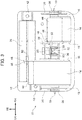
- the ankle and toe training apparatus 10 includes a base 12 that is placed on a floor or other surface.
- the base 12 is a rectangular plate having a longitudinal direction in the left-right direction in plan view (from the top side).
- the ankle and toe training apparatus 10 also includes a pair of left and right foot flatforms 14 each configured to receive the user's foot and disposed to face a portion of the user's foot from rearfoot to forefoot.
- the foot platform 14 is a rectangular plate having a longitudinal direction in the direction from the rearfoot to forefoot of the user's foot.
- a pair of sidewall plates 16 are fixed to both of the left and right ends of the foot platform 14.
- the sidewall plates 16 are triangular in side view (as viewed from the left or right side).
- the left and right sidewall plates 16 extend in parallel with each other with their thickness direction in the left-right direction.
- a rotating shaft 18 having an axial direction in the left-right direction is fixed to the left sidewall plate 16 fixed to the left foot platform 14.
- a rotating shaft 20 having an axial direction in the left-right direction is inserted into the right sidewall plate 16 fixed to the left foot platform 14.
- a tilting angle limiting plate 22 is fixed to the rotating shaft 20.
- the tilting angle limiting plate 22 is substantially fan-shaped in side view and disposed along the right sidewall plate 16 fixed to the left foot platform 14.
- the tilting angle limiting plate 22 has plural pin receiving holes 22A into one of which a pin 24 is inserted.
- the right sidewall plate 16 fixed to the left foot platform 14 has a pin receiving hole (not shown) into which the pin 24 is inserted.
- the tilting angle limiting plate 22 is displaced (tilted) around the rotating shaft 20 as an axis together with the right sidewall plate 16 fixed to the left foot platform 14.
- the tilting angle limiting plate 22 comes into contact with the base 12 as a result of the displacement together with the right sidewall plate 16 fixed to the left foot platform 14, the tilting of the left foot platform 14 in the dorsiflexion direction (indicated by the arrow A) is limited.
- the maximum angle of tilting of the left foot platform 14 in the dorsiflexion direction is adjustable by changing the position at which the pin 24 is inserted into one of the pin receiving holes 22A.
- a rotating shaft 18 having an axial direction in the left-right direction is also fixed to the right sidewall plate 16 fixed to the right foot platform 14.
- a rotating shaft 20 having an axial direction in the left-right direction is also inserted into the left sidewall plate 16 fixed to the right foot platform 14, and a tilting angle limiting plate 22 is fixed to the rotating shaft 20.
- the relationship between the tilting angle limiting plate 22 and the left sidewall plate 16 fixed to the right foot platform 14 is the same as that described above between the tilting angle limiting plate 22 and the right sidewall plate 16 fixed to the left foot platform 14.
- the rotating shafts 20 disposed at the left-right directional center of the ankle and toe training apparatus 10 are rotatably supported on a gear box 28, which is described later.
- the rotating shafts 18 disposed on both of the left-right directional sides of the ankle and toe training apparatus 10 are each rotatably supported on a support plate 26 fixed to the base 12. Therefore, the foot platforms 14 are each tilted (rotated) in the dorsiflexion and plantar flexion directions (top-bottom directions) around the rotating shafts 18 and 20 as axes.
- the gear box 28, which is box-shaped, is provided between the left and right foot platforms 14.
- the gear box 28 is fixed to the base 12.
- a bevel gear 30 is fixed to each of the two rotating shafts 20 supported on the gear box 28.
- the bevel gear 30 fixed to one of the rotating shafts 20 is connected to the bevel gear 30 fixed to the other rotating shaft 20 with an interposed bevel gear 32 having an axial direction in the front-rear direction, rotatably supported on the gear box 28. As shown in FIGS.
- the tilting angle limiting plate 22 when the tilting angle limiting plate 22 is displaceable together with the sidewall plate 16 fixed to the foot platform 14 due to the pin 24 engaged with them, the rotation of one of the rotating shafts 20 is transmitted through the bevel gears 30 and 32 to rotate the other rotating shaft 20 in the reverse direction. Therefore, the left and right foot platforms 14 are tilted in a staggered manner. Specifically, when the right foot platform 14 is tilted upward, the left foot platform 14 is tilted downward, and when the left foot platform 14 is tilted upward, the right foot platform 14 is tilted downward.
- the tilting angle limiting plate 22 When the tilting angle limiting plate 22 is unconnected to the sidewall plate 16 fixed to the foot platform 14 (with the pin 24 detached), the rotation of one of the rotating shafts 20 is not transmitted to the other rotating shaft 20 through the bevel gears 30 and 32. In this case, the left and right foot platforms 14 can be each independently tilted.
- a pulley 36 is fixed to each of the two rotating shafts 18 supported on the left and right support plates 26.
- a wire 34 is put on each pulley 36.
- the wire 34 is pulled to rotate the pulley 36.
- the foot platform 14 is tilted in the dorsiflexion direction (indicated by the arrow A). It should be noted that the wire 34 is not shown in the drawings other than FIG. 1 .
- An artificial muscle supporting box 38 is fixed to a front-end portion of the base 12.
- the box 38 is shaped in a box having a longitudinal direction in the left-right direction.
- two artificial muscles 40 serving as actuators are disposed in parallel with each other in the left-right direction.
- the artificial muscles 40 according to an embodiment are what are called McKibben artificial muscles.
- the artificial muscles 40 each include an elastic tube made of a tube-shaped elastic material such as tube-shaped rubber; and a tubular mesh sleeve that covers the elastic tube, in which the elastic tube covered with the mesh sleeve has both ends swaged. Gas (air) is supplied into the elastic tube to contract the artificial muscle 40 in the left-right direction.
- the rear side one of the two artificial muscles 40 has a right end fixed to the artificial muscle supporting box 38 and has a left end connected to the left pulley 36 through the wire 34.
- the front side one of the two artificial muscles 40 has a left end fixed to the artificial muscle supporting box 38 and has a right end connected to the right pulley 36 through the wire 34.
- An intermediate portion of the wire 34 between the artificial muscle 40 and the pulley 36 is guided and bent in an L-shape by a guide pulley 42 having an axial direction in the top-bottom direction, rotatably supported on the base 12.
- a toe platform 44 is attached to the front end of each of the left and right foot platforms 14.
- the toe platform 44 is plate-shaped like the foot platform 14 and disposed to face the user's toe.
- the toe platform 44 is attached via a hinge (not shown) to the foot platform 14 so that the toe platform 44 can be tilted in the top-bottom direction around an axis in the left-right direction with respect to the foot platform 14.
- a link engaging part 46 is fixed to each of right and left end portions of the left and right toe platforms 44.
- a toe extending link 48 described later is engaged with each link engaging part 46.
- the link engaging part 46 has a pin receiving hole 46A into which a pin 52, described later, is inserted. It should be noted that the link engaging part 46 is part of the toe platform 44. Alternatively, the toe platform 44 and the link engaging part 46 may be integrally formed.
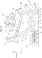
- the left link engaging part 46 is connected to the gear box 28 via the toe extending link 48 as a connecting member, and the right link engaging part 46 is connected to the gear box 28 via the toe extending link 48.
- the toe extending link 48 is in the form of a plate having a thickness direction in the left-right direction.
- the toe extending link 48 has one end supported with a pin 50 on the gear box 28 in such a way that it can be tilted (rotated) around an axis in the left-right direction.
- the toe extending link 48 has the other end in a substantially T-shape.
- the other end of the toe extending link 48 has plural pin receiving holes 48A.
- a pin 52 is inserted into one of the pin receiving holes 48A of the toe extending link 48 and into the pin receiving hole 46A of the link engaging part 46, so that the other end of the toe extending link 48 is engaged with the link engaging part 46.
- the toe extending link 48 allows the toe platform 44 to be inclined in the extension direction (indicated by the arrow B) with respect to the foot platform 14. Further, when the foot platform 14 is tilted in the dorsiflexion direction (indicated by the arrow A), the toe extending link 48 allows the toe platform 44 to be inclined in the flexion direction (reverse to the direction indicated by the arrow B) with respect to the foot platform 14.
- the position at which the pin 52 is inserted into one of the plural pin receiving holes 48A of the toe extending link 48 can be changed so that the angle at which the toe platform 44 is inclined with respect to the foot platform 14 being tilted can be adjusted.
- the ankle and toe training apparatus 10 may have holding members 54 each fixed to the foot platform 14.
- Each holding member 54 is configured to hold the user's foot on the foot platform 14.
- the holding member 54 includes a bottom portion 54A, a belt 54B, and other components.
- the bottom portion 54A is disposed along the foot platform 14 and the toe platform 44 and configured to stop the user's heel.
- the belt 54B is configured to be put around the user's ankle or the like.
- the holding members 54 may be commercially available sandals or other products.
- the sidewall plate 16 fixed to the foot platform 14 may be displaced together with the tilting angle limiting plate 22 with the pin 24 connecting them.
- FIG. 6 does not specifically show the extension of the toe of the left foot P1. Further, the user's right foot is dorsiflexed.
- the left foot platform 14 When the rear side one of the two artificial muscles 40 is contracted, the left foot platform 14 is tilted in the dorsiflexion direction (indicated by the arrow A) and the left toe platform 44 is inclined in the flexion direction (reverse to the direction indicated by the arrow B) with respect to the foot platform 14.
- the right foot platform 14 In synchronization with this, the right foot platform 14 is tilted in the plantar flexion direction (reverse to the direction indicated by the arrow A) and the right toe platform 44 is inclined in the extension direction (indicated by the arrow B) with respect to the foot platform 14. Therefore, the user's right foot is plantarflexed.
- the user's left foot P1 is dorsiflexed.
- the left and right foot platforms 14 and the left and right toe platforms 44 are alternately moved as described above. This allows the user's lower extremities P to move like real walking (in a way to mimic the four-joint rotation link).
- the ankle and toe training apparatus 10 can provide better service results by extending the toes.
- the apparatus 10 is effective in rehabilitation for walking since it allows the user's lower extremities P to move like real walking, which is accompanied by extension of the toes.
- the user can press the heels against the bottom portions 54A of the holding members 54 and use the ankle and toe training apparatus 10 to effectively carry out rehabilitation for walking.
- the position at which the pin 52 is inserted into one of the plural pin receiving holes 48A of the toe extending link 48 can be changed so that the angle at which the toe platform 44 is inclined with respect to the foot platform 14 being tilted can be adjusted. This allows easy adjustment of the load for the extension of the toe.
- the position at which the pin 24 is inserted into one of the plural pin receiving holes 22A of the tilting angle limiting plate 22 shown in FIG. 2 can be changed so that the maximum angle at which the foot platform 14 is tilted in the dorsiflexion direction can be adjusted. This allows easy adjustment of the load for the dorsiflexion of the foot.
- the sidewall plate 16 fixed to the foot platform 14 may not be displaced together with the tilting angle limiting plate 22 with the pin 24 detached from them.
- the left foot platform 14 is tilted in the dorsiflexion direction (indicated by the arrow A) and the left toe platform 44 is inclined in the flexion direction (reverse to the direction indicated by the arrow B) with respect to the foot platform 14.
- the right foot platform 14 and the right toe platform 44 are not tilted.
- the right foot platform 14 When the front side one of the two artificial muscles 40 is contracted, the right foot platform 14 is tilted in the dorsiflexion direction (indicated by the arrow A) and the right toe platform 44 is inclined in the flexion direction (reverse to the direction indicated by the arrow B) with respect to the foot platform 14. At this time, the left foot platform 14 and the left toe platform 44 are not tilted.
- the left and right foot platforms 14 are simultaneously tilted in the dorsiflexion direction (indicated by the arrow A) and the left and right toe platforms 44 are simultaneously inclined in the flexion direction (reverse to the direction indicated by the arrow B) with respect to the foot platforms 14.
- the artificial muscles 40 are each adopted as an actuator for tilting the foot platform 14 and the toe platform 44. Therefore, the gas contained in each artificial muscle 40 can reduce the impact from the foot platform 14 onto the user's foot.
- FIG. 8 shows an ankle and toe training apparatus 56 according to another embodiment of the present invention, which includes motors 58 as actuators.
- the ankle and toe training apparatus 56 works with the same level of force to tilt the foot platforms 14 and the toe platforms 44 as that in the ankle and toe training apparatus 10 described above.
- the size of the ankle and toe training apparatus 56 (in particular, the size in the left-right direction) is apparently larger than that of the ankle and toe training apparatus 10 described above.
- the mass of the ankle and toe training apparatus 56 is also larger than that of the ankle and toe training apparatus 10 described above.
- the type of the actuator for tilting the foot platform 14 and the toe platform 44 may be selected as desired in consideration of the service conditions for the ankle and toe training apparatus and other factors.
Landscapes
- Health & Medical Sciences (AREA)
- Physical Education & Sports Medicine (AREA)
- General Health & Medical Sciences (AREA)
- Orthopedic Medicine & Surgery (AREA)
- Epidemiology (AREA)
- Pain & Pain Management (AREA)
- Rehabilitation Therapy (AREA)
- Life Sciences & Earth Sciences (AREA)
- Animal Behavior & Ethology (AREA)
- Public Health (AREA)
- Veterinary Medicine (AREA)
- Rehabilitation Tools (AREA)
Applications Claiming Priority (2)
| Application Number | Priority Date | Filing Date | Title |
|---|---|---|---|
| JP2018018456A JP2019134889A (ja) | 2018-02-05 | 2018-02-05 | 足首及び足指の機能訓練装置 |
| PCT/JP2019/002124 WO2019151086A1 (fr) | 2018-02-05 | 2019-01-23 | Dispositif d'entraînement de la fonction cheville et orteil |
Publications (2)
| Publication Number | Publication Date |
|---|---|
| EP3738573A1 true EP3738573A1 (fr) | 2020-11-18 |
| EP3738573A4 EP3738573A4 (fr) | 2021-04-14 |
Family
ID=67479211
Family Applications (1)
| Application Number | Title | Priority Date | Filing Date |
|---|---|---|---|
| EP19746688.1A Withdrawn EP3738573A4 (fr) | 2018-02-05 | 2019-01-23 | Dispositif d'entraînement de la fonction cheville et orteil |
Country Status (5)
| Country | Link |
|---|---|
| US (1) | US20210212878A1 (fr) |
| EP (1) | EP3738573A4 (fr) |
| JP (1) | JP2019134889A (fr) |
| CN (1) | CN111683637A (fr) |
| WO (1) | WO2019151086A1 (fr) |
Families Citing this family (3)
| Publication number | Priority date | Publication date | Assignee | Title |
|---|---|---|---|---|
| US12539445B2 (en) * | 2015-06-01 | 2026-02-03 | Richard Duenas | Squat and spinal fitness and rehabilitation device |
| CN111012622B (zh) * | 2019-11-27 | 2025-06-20 | 合肥工业大学 | 训练装置 |
| CN112022648B (zh) * | 2020-09-02 | 2024-05-17 | 华侨大学 | 一种以前端伸缩按摩脚趾的康复训练装置 |
Family Cites Families (12)
| Publication number | Priority date | Publication date | Assignee | Title |
|---|---|---|---|---|
| GB8707591D0 (en) * | 1987-03-31 | 1987-05-07 | Heaton S | Leg exerciser |
| US5267924A (en) * | 1993-01-07 | 1993-12-07 | Advanced Kinetics, Inc. | Apparatus and method for imparting continuous passive motion to the foot |
| JP2000342714A (ja) * | 1999-06-07 | 2000-12-12 | Yoshihiro Kimura | 椅子に腰掛けて足首、足指を屈伸する運動具 |
| JP2002143269A (ja) * | 2000-11-08 | 2002-05-21 | Shinko Denshi Kk | 足首・足指運動用健康器 |
| JP4085422B2 (ja) * | 2002-09-04 | 2008-05-14 | 株式会社安川電機 | 関節駆動装置 |
| WO2004085856A1 (fr) * | 2003-03-25 | 2004-10-07 | Hitachi Medical Corporation | Actionneur a pression hydraulique et dispositif d'exercice manuel continu comprenant cet actionneur |
| GB2446757B (en) * | 2005-12-28 | 2010-11-17 | Eiko Entpr Co Ltd | Toe massage device |
| US20080051682A1 (en) * | 2006-08-25 | 2008-02-28 | Thomas Pete G | Continuous passive motion device for a toe |
| JPWO2009122480A1 (ja) * | 2008-03-31 | 2011-07-28 | パナソニック電工株式会社 | 運動装置 |
| EP2815793B1 (fr) * | 2013-06-17 | 2018-09-05 | schepp medtech GmbH | Dispositif de mouvement de vitesse |
| KR101600600B1 (ko) * | 2013-11-20 | 2016-03-08 | 조재민 | 족부 스트레칭 장치 |
| JP6695720B2 (ja) | 2016-03-22 | 2020-05-20 | 株式会社エヌエステイー | 足首ストレッチ装置 |
-
2018
- 2018-02-05 JP JP2018018456A patent/JP2019134889A/ja active Pending
-
2019
- 2019-01-23 CN CN201980011674.2A patent/CN111683637A/zh active Pending
- 2019-01-23 EP EP19746688.1A patent/EP3738573A4/fr not_active Withdrawn
- 2019-01-23 US US16/967,532 patent/US20210212878A1/en not_active Abandoned
- 2019-01-23 WO PCT/JP2019/002124 patent/WO2019151086A1/fr not_active Ceased
Also Published As
| Publication number | Publication date |
|---|---|
| WO2019151086A1 (fr) | 2019-08-08 |
| US20210212878A1 (en) | 2021-07-15 |
| EP3738573A4 (fr) | 2021-04-14 |
| JP2019134889A (ja) | 2019-08-15 |
| CN111683637A (zh) | 2020-09-18 |
Similar Documents
| Publication | Publication Date | Title |
|---|---|---|
| JP4816795B2 (ja) | 他動運動機器 | |
| EP3738573A1 (fr) | Dispositif d'entraînement de la fonction cheville et orteil | |
| EP2263761A1 (fr) | Appareil d'exercice | |
| KR102349103B1 (ko) | 신경계 질환용 하지 재활장치 | |
| KR102611914B1 (ko) | 보행 보조 장치 | |
| KR100856847B1 (ko) | 보행 보조 장치 | |
| WO2009081935A1 (fr) | Dispositif d'aide à l'exercice | |
| ITFI950208A1 (it) | Attrezzo per l'esecuzione di esercizi di flessione antero-posteriore del piede e degli arti inferiori | |
| WO2006126705A1 (fr) | Appareil d'assistance a l'exercice | |
| JP5033198B2 (ja) | 運動補助装置 | |
| KR101974559B1 (ko) | 평발 교정용 운동 기구 | |
| JP2018033641A (ja) | 脚の筋肉萎縮防止装置 | |
| KR20220132372A (ko) | 평발 교정 보조기구 | |
| JP5509396B2 (ja) | 下肢運動補助装置 | |
| KR20100136526A (ko) | 운동 보조 장치 | |
| KR20190101848A (ko) | 효율적인 보조력 전달을 위한 근력 보조 로봇 | |
| JP5032838B2 (ja) | 運動補助装置 | |
| KR101846381B1 (ko) | 발 뒤꿈치의 스웨이 모션을 제공하는 로봇 다리 장치 및 의족 장치 | |
| KR20220132373A (ko) | 양발 사용이 가능한 평발 교정 보조기구 | |
| JP2018175239A (ja) | 評価装置及び評価方法 | |
| JP2004181163A (ja) | 足首運動器 | |
| KR102483423B1 (ko) | 종아리근육 신장 진동기구 | |
| KR100850885B1 (ko) | 운동기구용 바이브레이타 | |
| JP2014004138A (ja) | 下肢運動補助装置 | |
| KR101476989B1 (ko) | 하체운동기구 |
Legal Events
| Date | Code | Title | Description |
|---|---|---|---|
| STAA | Information on the status of an ep patent application or granted ep patent |
Free format text: STATUS: THE INTERNATIONAL PUBLICATION HAS BEEN MADE |
|
| PUAI | Public reference made under article 153(3) epc to a published international application that has entered the european phase |
Free format text: ORIGINAL CODE: 0009012 |
|
| STAA | Information on the status of an ep patent application or granted ep patent |
Free format text: STATUS: REQUEST FOR EXAMINATION WAS MADE |
|
| 17P | Request for examination filed |
Effective date: 20200811 |
|
| AK | Designated contracting states |
Kind code of ref document: A1 Designated state(s): AL AT BE BG CH CY CZ DE DK EE ES FI FR GB GR HR HU IE IS IT LI LT LU LV MC MK MT NL NO PL PT RO RS SE SI SK SM TR |
|
| AX | Request for extension of the european patent |
Extension state: BA ME |
|
| A4 | Supplementary search report drawn up and despatched |
Effective date: 20210312 |
|
| RIC1 | Information provided on ipc code assigned before grant |
Ipc: A61H 1/02 20060101AFI20210305BHEP Ipc: A63B 23/08 20060101ALI20210305BHEP Ipc: A63B 24/00 20060101ALI20210305BHEP |
|
| DAV | Request for validation of the european patent (deleted) | ||
| DAX | Request for extension of the european patent (deleted) | ||
| GRAP | Despatch of communication of intention to grant a patent |
Free format text: ORIGINAL CODE: EPIDOSNIGR1 |
|
| STAA | Information on the status of an ep patent application or granted ep patent |
Free format text: STATUS: GRANT OF PATENT IS INTENDED |
|
| INTG | Intention to grant announced |
Effective date: 20220203 |
|
| STAA | Information on the status of an ep patent application or granted ep patent |
Free format text: STATUS: THE APPLICATION IS DEEMED TO BE WITHDRAWN |
|
| 18D | Application deemed to be withdrawn |
Effective date: 20220614 |