EP3738661A1 - Katalysierter partikelfilter für verbrennungsmotor mit gesteuerter zündung - Google Patents
Katalysierter partikelfilter für verbrennungsmotor mit gesteuerter zündung Download PDFInfo
- Publication number
- EP3738661A1 EP3738661A1 EP20165376.3A EP20165376A EP3738661A1 EP 3738661 A1 EP3738661 A1 EP 3738661A1 EP 20165376 A EP20165376 A EP 20165376A EP 3738661 A1 EP3738661 A1 EP 3738661A1
- Authority
- EP
- European Patent Office
- Prior art keywords
- load
- inlet
- impregnation
- filter
- platinum group
- Prior art date
- Legal status (The legal status is an assumption and is not a legal conclusion. Google has not performed a legal analysis and makes no representation as to the accuracy of the status listed.)
- Pending
Links
- 239000002245 particle Substances 0.000 title description 6
- 238000002485 combustion reaction Methods 0.000 title description 3
- 238000006555 catalytic reaction Methods 0.000 title 1
- 238000005470 impregnation Methods 0.000 claims abstract description 29
- BASFCYQUMIYNBI-UHFFFAOYSA-N platinum Chemical group [Pt] BASFCYQUMIYNBI-UHFFFAOYSA-N 0.000 claims abstract description 29
- 239000011248 coating agent Substances 0.000 claims abstract description 24
- 238000000576 coating method Methods 0.000 claims abstract description 24
- 229910052751 metal Inorganic materials 0.000 claims abstract description 24
- 239000002184 metal Substances 0.000 claims abstract description 24
- 239000003054 catalyst Substances 0.000 claims abstract description 19
- 239000000203 mixture Substances 0.000 claims abstract description 10
- 239000000758 substrate Substances 0.000 claims description 22
- 239000000567 combustion gas Substances 0.000 claims description 8
- 239000010970 precious metal Substances 0.000 claims description 8
- 230000003197 catalytic effect Effects 0.000 claims description 5
- 230000001747 exhibiting effect Effects 0.000 claims description 4
- 229910052697 platinum Inorganic materials 0.000 claims description 3
- -1 platinum group metals Chemical class 0.000 abstract 1
- MWUXSHHQAYIFBG-UHFFFAOYSA-N nitrogen oxide Inorganic materials O=[N] MWUXSHHQAYIFBG-UHFFFAOYSA-N 0.000 description 17
- 239000007789 gas Substances 0.000 description 14
- UGFAIRIUMAVXCW-UHFFFAOYSA-N Carbon monoxide Chemical compound [O+]#[C-] UGFAIRIUMAVXCW-UHFFFAOYSA-N 0.000 description 8
- 229910002091 carbon monoxide Inorganic materials 0.000 description 8
- 229930195733 hydrocarbon Natural products 0.000 description 8
- 150000002430 hydrocarbons Chemical class 0.000 description 8
- 239000010419 fine particle Substances 0.000 description 4
- KDLHZDBZIXYQEI-UHFFFAOYSA-N Palladium Chemical compound [Pd] KDLHZDBZIXYQEI-UHFFFAOYSA-N 0.000 description 3
- 239000000463 material Substances 0.000 description 3
- 150000002739 metals Chemical class 0.000 description 3
- 230000009466 transformation Effects 0.000 description 3
- QGZKDVFQNNGYKY-UHFFFAOYSA-N Ammonia Chemical compound N QGZKDVFQNNGYKY-UHFFFAOYSA-N 0.000 description 2
- 239000000919 ceramic Substances 0.000 description 2
- 238000001914 filtration Methods 0.000 description 2
- 239000012041 precatalyst Substances 0.000 description 2
- 239000010948 rhodium Substances 0.000 description 2
- 238000011144 upstream manufacturing Methods 0.000 description 2
- 239000000853 adhesive Substances 0.000 description 1
- 230000001070 adhesive effect Effects 0.000 description 1
- 229910021529 ammonia Inorganic materials 0.000 description 1
- 238000009924 canning Methods 0.000 description 1
- 239000004568 cement Substances 0.000 description 1
- 230000007547 defect Effects 0.000 description 1
- 230000000593 degrading effect Effects 0.000 description 1
- 239000003344 environmental pollutant Substances 0.000 description 1
- 238000001125 extrusion Methods 0.000 description 1
- 239000000945 filler Substances 0.000 description 1
- 238000011068 loading method Methods 0.000 description 1
- 229910052763 palladium Inorganic materials 0.000 description 1
- 239000012466 permeate Substances 0.000 description 1
- 231100000719 pollutant Toxicity 0.000 description 1
- 229910052703 rhodium Inorganic materials 0.000 description 1
- MHOVAHRLVXNVSD-UHFFFAOYSA-N rhodium atom Chemical compound [Rh] MHOVAHRLVXNVSD-UHFFFAOYSA-N 0.000 description 1
Images


Classifications
-
- B—PERFORMING OPERATIONS; TRANSPORTING
- B01—PHYSICAL OR CHEMICAL PROCESSES OR APPARATUS IN GENERAL
- B01D—SEPARATION
- B01D53/00—Separation of gases or vapours; Recovering vapours of volatile solvents from gases; Chemical or biological purification of waste gases, e.g. engine exhaust gases, smoke, fumes, flue gases, aerosols
- B01D53/34—Chemical or biological purification of waste gases
- B01D53/92—Chemical or biological purification of waste gases of engine exhaust gases
- B01D53/94—Chemical or biological purification of waste gases of engine exhaust gases by catalytic processes
- B01D53/9445—Simultaneously removing carbon monoxide, hydrocarbons or nitrogen oxides making use of three-way catalysts [TWC] or four-way-catalysts [FWC]
- B01D53/945—Simultaneously removing carbon monoxide, hydrocarbons or nitrogen oxides making use of three-way catalysts [TWC] or four-way-catalysts [FWC] characterised by a specific catalyst
-
- B—PERFORMING OPERATIONS; TRANSPORTING
- B01—PHYSICAL OR CHEMICAL PROCESSES OR APPARATUS IN GENERAL
- B01D—SEPARATION
- B01D46/00—Filters or filtering processes specially modified for separating dispersed particles from gases or vapours
- B01D46/24—Particle separators, e.g. dust precipitators, using rigid hollow filter bodies
- B01D46/2403—Particle separators, e.g. dust precipitators, using rigid hollow filter bodies characterised by the physical shape or structure of the filtering element
- B01D46/2418—Honeycomb filters
-
- B—PERFORMING OPERATIONS; TRANSPORTING
- B01—PHYSICAL OR CHEMICAL PROCESSES OR APPARATUS IN GENERAL
- B01D—SEPARATION
- B01D53/00—Separation of gases or vapours; Recovering vapours of volatile solvents from gases; Chemical or biological purification of waste gases, e.g. engine exhaust gases, smoke, fumes, flue gases, aerosols
- B01D53/34—Chemical or biological purification of waste gases
- B01D53/92—Chemical or biological purification of waste gases of engine exhaust gases
- B01D53/94—Chemical or biological purification of waste gases of engine exhaust gases by catalytic processes
- B01D53/9459—Removing one or more of nitrogen oxides, carbon monoxide, or hydrocarbons by multiple successive catalytic functions; systems with more than one different function, e.g. zone coated catalysts
- B01D53/9463—Removing one or more of nitrogen oxides, carbon monoxide, or hydrocarbons by multiple successive catalytic functions; systems with more than one different function, e.g. zone coated catalysts with catalysts positioned on one brick
- B01D53/9468—Removing one or more of nitrogen oxides, carbon monoxide, or hydrocarbons by multiple successive catalytic functions; systems with more than one different function, e.g. zone coated catalysts with catalysts positioned on one brick in different layers
-
- B—PERFORMING OPERATIONS; TRANSPORTING
- B01—PHYSICAL OR CHEMICAL PROCESSES OR APPARATUS IN GENERAL
- B01D—SEPARATION
- B01D2255/00—Catalysts
- B01D2255/10—Noble metals or compounds thereof
- B01D2255/102—Platinum group metals
-
- B—PERFORMING OPERATIONS; TRANSPORTING
- B01—PHYSICAL OR CHEMICAL PROCESSES OR APPARATUS IN GENERAL
- B01D—SEPARATION
- B01D2255/00—Catalysts
- B01D2255/90—Physical characteristics of catalysts
- B01D2255/902—Multilayered catalyst
- B01D2255/9022—Two layers
-
- B—PERFORMING OPERATIONS; TRANSPORTING
- B01—PHYSICAL OR CHEMICAL PROCESSES OR APPARATUS IN GENERAL
- B01D—SEPARATION
- B01D2255/00—Catalysts
- B01D2255/90—Physical characteristics of catalysts
- B01D2255/915—Catalyst supported on particulate filters
- B01D2255/9155—Wall flow filters
-
- Y—GENERAL TAGGING OF NEW TECHNOLOGICAL DEVELOPMENTS; GENERAL TAGGING OF CROSS-SECTIONAL TECHNOLOGIES SPANNING OVER SEVERAL SECTIONS OF THE IPC; TECHNICAL SUBJECTS COVERED BY FORMER USPC CROSS-REFERENCE ART COLLECTIONS [XRACs] AND DIGESTS
- Y02—TECHNOLOGIES OR APPLICATIONS FOR MITIGATION OR ADAPTATION AGAINST CLIMATE CHANGE
- Y02T—CLIMATE CHANGE MITIGATION TECHNOLOGIES RELATED TO TRANSPORTATION
- Y02T10/00—Road transport of goods or passengers
- Y02T10/10—Internal combustion engine [ICE] based vehicles
- Y02T10/12—Improving ICE efficiencies
Definitions
- the present invention relates to a catalyzed particulate filter for the depollution of combustion gases from an internal combustion engine of the spark-ignition type. It finds a particularly advantageous application in motor vehicles equipped with such engines.
- such a catalyst is generally in the form of a monolith of ceramic or metallic substrate with continuous flow, comprising a plurality of longitudinal channels through which the combustion gases flow right through.
- the side walls delimiting the gas flow channels are impregnated with at least one impregnating coating (also called “washcoat” in English) comprising a catalytic composition comprising at least one metal from the platinum group (also called “PGM” according to l. acronym for: Platinum Group Metal).
- PGM platinum group
- the figure 1 is an isometric perspective view which schematically represents an example of the structure of such a catalyzed particulate filter (also known as GPFc, from the acronym for: catalyzed Gasoline Particulate Filter).
- Filter 1 comprises a structured block honeycomb 2, or substrate monolith 2, in which a plurality of bodies 3, for example baked ceramic honeycomb bodies 3 (36 in number in the figure), in the form of pillars, are combined with each other with a layer of adhesive 4, or cement 4.
- the less central segments 3 of the substrate monolith 2 can be cut such that the substrate monolith 2 has for example a shape cylinder of revolution.
- a waterproof material 5, or outer skin 5, covers the substrate monolith 2 thus delimited over its entire cylindrical lateral surface.
- the particulate filter thus formed is generally housed in a metal casing (or “canning”, not shown) mounted in the exhaust circuit of the engine.
- the combustion gases emitted by the engine circulate in the particle filter 1 in the direction of the arrow G indicated on the figure 1 .
- the figure 2 is an isometric perspective view which schematically represents one of the segments 3 which make up the monolith of substrate 2.
- Segment 3 is here in the form of a pillar, more precisely of a parallelepiped of length L (in the direction of circulation gases represented by the arrow G) and with a square base on the side C.
- Its structure consists of a large number of channels 6, or cells 6, placed longitudinally (ie in the direction of gas circulation) and parallel to each other. compared to the others, with a wall 7 interposed between them.
- channels 6 have in a nonlimiting manner, a square section (in a plane perpendicular to the direction of gas flow).
- all the channels have the same size and are separated by walls of identical thickness.
- the channels may have different shapes, for example with an octagonal or hexagonal section, and / or have walls of varying thickness.
- One or the other of the ends of each channel is closed by a tight plug.
- the figure 3 is a section according to plane AA of the figure 2 , which illustrates the flow of combustion gases from the engine through a segment 3 of the particulate filter.
- the gases arrive on an inlet face of the segments 3 in the direction of arrow G, and exit through an outlet face.
- the gases enter those of the channels 6, the upstream end of which is not blocked by a plug 8, also called inlet channels.
- the gases leave segment 3 through the channels 6 adjacent to said inlet channels and the downstream end of which is not blocked by a plug 8, also called outlet channels, after passing through the wall 7 which separates the two adjacent channels over almost its entire length, with the exception of the inlet and outlet sections which adjoin the stoppers.
- the different walls 7 have a capacity for filtering (or more precisely: for retaining) the fine particles PM emitted in the combustion gases of the engine, which a conventional monolith substrate of the continuous flow type does not have.
- a filter is said to flow through the walls (“wall through” according to the English designation).
- the treatment of other polluting molecules (HC, CO and NOx) which are usually transformed by a three-way catalyst is provided in such a filter 1 by impregnation of the substrate monolith with at least one coating of impregnator comprising a catalytic composition comprising at least one metal of the platinum group (PGM).
- the coating impregnates the lateral surface of the channels over at least part of their length, preferably over their entire length, and it may penetrate more or less deeply inside the porous structure of the walls 7 it. -even.
- the substrate monolith may consist of a single extruded block, which is shaped directly to its shape (e.g. cylindrical) at the moment when the material that composes it is pushed and shaped.
- the skin 5 is generally formed naturally during extrusion by the material itself.
- catalyzed particulate filters which are of the wall-flow type, are less efficient than catalysts. continuous flow because it is necessary to substantially limit the impregnation of the substrate monolith, in order to maintain a back pressure in the filter which allows the gases to pass through the walls.
- the amount of impregnating coating, or WCL impregnation charge is most often greater than or equal to 200 g / l, for example included between 200 and 250 g / l and this coating comprises a load of precious metals, more precisely a load of metals from the platinum group (or PGM) which depends on the location of the catalyst in the engine exhaust circuit.
- the load may be of the order of a few tens to a few hundred grams per cubic foot (g / ft 3 ), for example between 60 and 250 g / ft 3 , for a pre-catalyst or so-called “close” catalyst, that is to say mounted in the immediate vicinity of the engine, generally in the engine compartment of the vehicle, for a rapid rise in temperature.
- the load can be of the order of a few tens of grams per cubic foot, for example between 10 and 60 g / ft 3 , in the case of a main catalyst which can be mounted directly behind the pre-catalyst or in position.
- "Under body" That is to say mounted at a distance from the engine, under the body of the vehicle.
- a catalyzed particle filter it is usually necessary to limit oneself to a quantity of impregnating coating of between 25 and 120 g / l (sometimes up to 150 g / l), comprising a load of precious metals PGM corresponding to the load of a catalyst under the body, for example between 10 and 60 g / ft 3 , to allow the gas to flow through the walls, even if the filter is of the close type.
- the charge of precious metals generally comprises a mixture of platinum Pt and / or of palladium Pd and / or of rhodium Rh. It is understood that the capacity of The treatment of HC, CO and NOx from such filters is reduced compared to a conventional three-way catalyst.
- WO2016 / 160915A1 discloses a catalyzed particulate filter for a lean-burn engine.
- the filter is of the wall flow type as described in the figures 1 to 3 , and it has on its outlet face comprising the plugs closing off the gas inlet channels, and over a length which does not exceed 1.5 times the length of the plugs, an impregnation coating comprising a metal from the platinum group which is able to trap ammonia leaks at the outlet of the filter.
- this coating and more particularly its location on the rear face does not make it possible to ensure the treatment of the HC, CO and NOx contained in the incoming gases.
- the present invention aims to resolve the defects of catalyzed particulate filters for spark ignition engines known from the state of the art. More specifically, it aims to improve the treatment capacity of HC, CO and NOx catalyzed particle filters without increasing their size.
- a catalyzed particle filter for a spark-ignition engine of the wall-flow type, comprising a substrate monolith in which porous walls, extending longitudinally between an inlet face of the filter and a face of the filter.
- the outlet of the filter are traversed by combustion gases from the engine, said walls being interposed between, on the one hand, longitudinal inlet channels open on said inlet face and closed by a plug on said outlet face, and on the other hand, longitudinal outlet channels closed by a plug on said inlet face and open on said outlet face, said substrate monolith being impregnated over at least part of its length with at least one impregnator coating comprising a catalytic composition comprising at least one metal from the platinum group, said coating having a first impregnation filler relatively low with a relatively low initial platinum group metal load.
- the main characteristic of the filter according to the invention is that the substrate monolith comprises, on its inlet face and over an inlet length of the inlet channels which is less than or equal to the length of the plugs, a coating of An additional impregnator comprising a catalyst composition comprising at least one platinum group metal, said coating exhibiting a relatively high second impregnation load with a relatively high second platinum group metal load.
- the catalyzed particulate filter according to the invention has the characteristics of the filter according to figures 1 to 3 which have been described above or according to variants not shown such as for example a filter having a single substrate of extruded monolith.
- it is a wall-flow type filter, with a substrate monolith which is impregnated with an impregnator coating comprising a catalytic composition comprising at least one platinum group metal (PGM).
- PGM platinum group metal
- this coating permeates the side surface of the channels over at least part of their length, preferably over their entire length, and it may be that it penetrates more or less deeply inside the channel. the porous structure of the walls 7 itself.
- this coating, or first coating has a first relatively low WCL impregnation load, for example between 25 and 150 g / l, comprising a first load of metals from the group relatively low PGM platinum, for example between 10 and 60 g / ft 3 .
- the filter 1 comprises, on its gas inlet face and over an inlet length of the inlet channels less than or equal to the length of the plugs, an additional impregnation, by a second coating of impregnator comprising at least one catalyst composition comprising at least one platinum group metal, said additional coating exhibiting a relatively high second impregnation load WCL, comprising a second relatively high platinum group precious metal load PGM.
- the relatively high second impregnation load WCL is at least 30% higher than the relatively low first impregnation load, with a deviation of at least 50 g / l more compared to the first load of impregnation.
- the second WCL impregnation load is comparable to the impregnation load of a very loaded conventional three-way catalyst, that is to say greater than 200 g / l, for example between 200 and 250 g / l.
- the relatively high second platinum group metal load PGM is at least 30% higher than the first platinum group metal load, 50 g / ft 3 than the first precious metal load. In a preferred embodiment, it is comparable to the impregnation load of a conventional three-way catalyst of the very loaded “close” type, that is to say of the order of a few hundred grams per cubic foot, by example between 150 and 250 g / ft 3 .
- the plugs 8 which close the channels 6, in particular the inlet channels, are in the form of parallelepipeds of length L B which are attached without play to the entry of the walls 7.
- the front face 11 of these plugs is flush with the face.
- front 10 of the inlet channels so that the front face of the substrate monolith, or of the filter, is a substantially planar surface comprising the front faces of the walls 7 of the channels and the front faces of the plugs 8 which close off the outlet channels .
- An additional coating of impregnator 9 is applied at least on the front face of the filter, and it can overflow inside the inlet channels on the side walls 7 of the inlet channels, over a length which does not exceed 1. end of the caps.
- the advantage of such a relatively high surface impregnation on the inlet face of the monolith substrate is that the precious metals deposited on the front face of the filter allow an increased transformation of the CO, HC and NOx pollutants contained in the gases. coming (almost perpendicularly) in contact with the front face.
- the additional impregnation inside the inlet channels allows the same improved transformation of the polluting molecules without having the disadvantage of degrading the backpressure in the filter, since the impregnation length is limited to the length plugs, which delimits an area which was in any case gas-tight because of the presence of the plug.
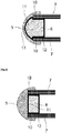
- the figure 5 represents another embodiment of the invention.
- the inlet plugs 8 have a head 13, for example of convex shape, which protrudes from the front face 10 of the inlet channels and which makes it possible to better guide the flow of gas entering the inlet channels.
- the additional impregnation 9 covers at least the inlet face of the filter, which consists of all the domed faces of the stopper heads 13, and parts of the front faces 10 of the inlet channels which are not not covered by the heads 13 of the plugs.
- the front face of the stoppers may be flat in accordance with FIG. 8, and the additional impregnation layer may have a thickness greater than the center of the caps only at their periphery, so that the front face of the impregnated filter has a shape similar to that of the figure 5 .
Landscapes
- Chemical & Material Sciences (AREA)
- Engineering & Computer Science (AREA)
- Chemical Kinetics & Catalysis (AREA)
- Health & Medical Sciences (AREA)
- Biomedical Technology (AREA)
- Environmental & Geological Engineering (AREA)
- Analytical Chemistry (AREA)
- General Chemical & Material Sciences (AREA)
- Oil, Petroleum & Natural Gas (AREA)
- Combustion & Propulsion (AREA)
- Physics & Mathematics (AREA)
- Geometry (AREA)
- Catalysts (AREA)
Applications Claiming Priority (1)
| Application Number | Priority Date | Filing Date | Title |
|---|---|---|---|
| FR1903728A FR3094648B1 (fr) | 2019-04-08 | 2019-04-08 | Filtre a particules catalyse pour moteur a combustion interne a allumage commande |
Publications (1)
| Publication Number | Publication Date |
|---|---|
| EP3738661A1 true EP3738661A1 (de) | 2020-11-18 |
Family
ID=67742660
Family Applications (1)
| Application Number | Title | Priority Date | Filing Date |
|---|---|---|---|
| EP20165376.3A Pending EP3738661A1 (de) | 2019-04-08 | 2020-03-24 | Katalysierter partikelfilter für verbrennungsmotor mit gesteuerter zündung |
Country Status (2)
| Country | Link |
|---|---|
| EP (1) | EP3738661A1 (de) |
| FR (1) | FR3094648B1 (de) |
Citations (3)
| Publication number | Priority date | Publication date | Assignee | Title |
|---|---|---|---|---|
| EP2161420A1 (de) * | 2008-09-05 | 2010-03-10 | Hyundai Motor Company | Abgasreinigungsvorrichtung |
| WO2016160915A1 (en) | 2015-03-30 | 2016-10-06 | Basf Corporation | Catalyzed filters with end coating for lean engine exhaust |
| US20180266290A1 (en) * | 2017-03-20 | 2018-09-20 | Johnson Matthey Public Limited Company | Rear on-wall design scrf |
-
2019
- 2019-04-08 FR FR1903728A patent/FR3094648B1/fr active Active
-
2020
- 2020-03-24 EP EP20165376.3A patent/EP3738661A1/de active Pending
Patent Citations (3)
| Publication number | Priority date | Publication date | Assignee | Title |
|---|---|---|---|---|
| EP2161420A1 (de) * | 2008-09-05 | 2010-03-10 | Hyundai Motor Company | Abgasreinigungsvorrichtung |
| WO2016160915A1 (en) | 2015-03-30 | 2016-10-06 | Basf Corporation | Catalyzed filters with end coating for lean engine exhaust |
| US20180266290A1 (en) * | 2017-03-20 | 2018-09-20 | Johnson Matthey Public Limited Company | Rear on-wall design scrf |
Also Published As
| Publication number | Publication date |
|---|---|
| FR3094648A1 (fr) | 2020-10-09 |
| FR3094648B1 (fr) | 2021-03-05 |
Similar Documents
| Publication | Publication Date | Title |
|---|---|---|
| EP2522822B1 (de) | System mit einem Verbrennungsmotor, einer U-Einheit zur Abgasnachbehandlung und einem optimisierten Hitzeschild | |
| WO2007088307A2 (fr) | Filtre catalytique presentant un temps d'amorcage reduit | |
| EP2426326A1 (de) | Partikelfilter mit drei katalytischen Beschichtungen | |
| EP2111281A1 (de) | Gasfiltrierstruktur mit gewellter wand | |
| FR2864575A1 (fr) | Bloc pour la filtration de particules contenues dans les gaz d'echappement d'un moteur a combustion interne | |
| FR3020091A1 (fr) | Filtre a particules | |
| EP1381464B1 (de) | Katalytischer reaktor mit einem katalysatorträger mit kreisenden kanal-netzwerken | |
| EP3738661A1 (de) | Katalysierter partikelfilter für verbrennungsmotor mit gesteuerter zündung | |
| EP1792064B1 (de) | Anordnung zum filtern der abgase eines verbrennungsmotors und dazugehörige abgasstrecke | |
| FR3042219A1 (fr) | Dispositif de post-traitement des gaz d’echappement d’un moteur a combustion | |
| EP1581728A1 (de) | Hilfssystem zur regeneration eines teilchenfilters für eineauslassleitung | |
| FR3037101A1 (fr) | Ligne d’echappement d’un moteur thermique | |
| EP3464847A1 (de) | Partikelfilter mit variabler kanalgeometrie und verfahren zur herstellung solch eines filters | |
| FR3006708A1 (fr) | Ensemble de post-traitement des gaz d'echappement d'un moteur thermique | |
| FR3041032A1 (fr) | Dispositif de post-traitement des gaz d’echappement d’un moteur a combustion | |
| EP1760281B1 (de) | Abgas- und Abgasreinigungsstrang einer Dieselbrennkraftmaschine für ein Fahrzeug und Fahrzeug mit einem solchen Strang | |
| FR2879236A1 (fr) | Filtre a particules a section de canaux variable | |
| EP1589199A1 (de) | Abgasreinigungsvorrichtung | |
| EP2439385A1 (de) | Verfahren zur Nachbehandlung von Abgasen eines Verbrennungsmotors | |
| FR3081730A1 (fr) | Filtre a particules pour moteur a combustion interne de moteur automobile | |
| FR2907158A1 (fr) | Monolithe ceramique pour filtre a particules de gaz d'echappement de vehicule automobile | |
| FR2939471A3 (fr) | Ligne d'echappement comportant un module de rechauffement des gaz d'echappement suivi d'un systeme de post-traitement des gaz d'echappement | |
| FR2955612A1 (fr) | Dispositif de post-traitement des gaz d'echappement d'un moteur a combustion | |
| FR2933448A1 (fr) | Dispositif de purification de gaz d'echappement | |
| FR2867508A1 (fr) | Filtre a particules pour ligne d'echappement d'un moteur a combustion interne et ligne d'echappement comprenant un tel filtre a particules. |
Legal Events
| Date | Code | Title | Description |
|---|---|---|---|
| PUAI | Public reference made under article 153(3) epc to a published international application that has entered the european phase |
Free format text: ORIGINAL CODE: 0009012 |
|
| STAA | Information on the status of an ep patent application or granted ep patent |
Free format text: STATUS: THE APPLICATION HAS BEEN PUBLISHED |
|
| AK | Designated contracting states |
Kind code of ref document: A1 Designated state(s): AL AT BE BG CH CY CZ DE DK EE ES FI FR GB GR HR HU IE IS IT LI LT LU LV MC MK MT NL NO PL PT RO RS SE SI SK SM TR |
|
| AX | Request for extension of the european patent |
Extension state: BA ME |
|
| STAA | Information on the status of an ep patent application or granted ep patent |
Free format text: STATUS: REQUEST FOR EXAMINATION WAS MADE |
|
| 17P | Request for examination filed |
Effective date: 20210518 |
|
| RBV | Designated contracting states (corrected) |
Designated state(s): AL AT BE BG CH CY CZ DE DK EE ES FI FR GB GR HR HU IE IS IT LI LT LU LV MC MK MT NL NO PL PT RO RS SE SI SK SM TR |
|
| RAP3 | Party data changed (applicant data changed or rights of an application transferred) |
Owner name: RENAULT S.A.S |
|
| RAP3 | Party data changed (applicant data changed or rights of an application transferred) |
Owner name: RENAULT S.A.S |
|
| P01 | Opt-out of the competence of the unified patent court (upc) registered |
Effective date: 20230608 |
|
| RAP1 | Party data changed (applicant data changed or rights of an application transferred) |
Owner name: NEW H POWERTRAIN HOLDING, S.L.U. |
|
| STAA | Information on the status of an ep patent application or granted ep patent |
Free format text: STATUS: EXAMINATION IS IN PROGRESS |
|
| 17Q | First examination report despatched |
Effective date: 20240529 |