EP3739174A1 - Vorrichtung zur erzeugung von strom aus druckluftenergiespeicher und verfahren zur erzeugung von strom aus druckluftenergiespeicher - Google Patents
Vorrichtung zur erzeugung von strom aus druckluftenergiespeicher und verfahren zur erzeugung von strom aus druckluftenergiespeicher Download PDFInfo
- Publication number
- EP3739174A1 EP3739174A1 EP18900459.1A EP18900459A EP3739174A1 EP 3739174 A1 EP3739174 A1 EP 3739174A1 EP 18900459 A EP18900459 A EP 18900459A EP 3739174 A1 EP3739174 A1 EP 3739174A1
- Authority
- EP
- European Patent Office
- Prior art keywords
- motors
- priority
- driven
- compressed air
- heat medium
- Prior art date
- Legal status (The legal status is an assumption and is not a legal conclusion. Google has not performed a legal analysis and makes no representation as to the accuracy of the status listed.)
- Withdrawn
Links
Images



Classifications
-
- F—MECHANICAL ENGINEERING; LIGHTING; HEATING; WEAPONS; BLASTING
- F02—COMBUSTION ENGINES; HOT-GAS OR COMBUSTION-PRODUCT ENGINE PLANTS
- F02C—GAS-TURBINE PLANTS; AIR INTAKES FOR JET-PROPULSION PLANTS; CONTROLLING FUEL SUPPLY IN AIR-BREATHING JET-PROPULSION PLANTS
- F02C6/00—Plural gas-turbine plants; Combinations of gas-turbine plants with other apparatus; Adaptations of gas-turbine plants for special use
- F02C6/14—Gas-turbine plants having means for storing energy, e.g. for meeting peak loads
- F02C6/16—Gas-turbine plants having means for storing energy, e.g. for meeting peak loads for storing compressed air
-
- F—MECHANICAL ENGINEERING; LIGHTING; HEATING; WEAPONS; BLASTING
- F01—MACHINES OR ENGINES IN GENERAL; ENGINE PLANTS IN GENERAL; STEAM ENGINES
- F01D—NON-POSITIVE DISPLACEMENT MACHINES OR ENGINES, e.g. STEAM TURBINES
- F01D17/00—Regulating or controlling by varying flow
-
- F—MECHANICAL ENGINEERING; LIGHTING; HEATING; WEAPONS; BLASTING
- F01—MACHINES OR ENGINES IN GENERAL; ENGINE PLANTS IN GENERAL; STEAM ENGINES
- F01D—NON-POSITIVE DISPLACEMENT MACHINES OR ENGINES, e.g. STEAM TURBINES
- F01D19/00—Starting of machines or engines; Regulating, controlling, or safety means in connection therewith
-
- F—MECHANICAL ENGINEERING; LIGHTING; HEATING; WEAPONS; BLASTING
- F02—COMBUSTION ENGINES; HOT-GAS OR COMBUSTION-PRODUCT ENGINE PLANTS
- F02C—GAS-TURBINE PLANTS; AIR INTAKES FOR JET-PROPULSION PLANTS; CONTROLLING FUEL SUPPLY IN AIR-BREATHING JET-PROPULSION PLANTS
- F02C1/00—Gas-turbine plants characterised by the use of hot gases or unheated pressurised gases, as the working fluid
- F02C1/02—Gas-turbine plants characterised by the use of hot gases or unheated pressurised gases, as the working fluid the working fluid being an unheated pressurised gas
-
- F—MECHANICAL ENGINEERING; LIGHTING; HEATING; WEAPONS; BLASTING
- F02—COMBUSTION ENGINES; HOT-GAS OR COMBUSTION-PRODUCT ENGINE PLANTS
- F02C—GAS-TURBINE PLANTS; AIR INTAKES FOR JET-PROPULSION PLANTS; CONTROLLING FUEL SUPPLY IN AIR-BREATHING JET-PROPULSION PLANTS
- F02C7/00—Features, components parts, details or accessories, not provided for in, or of interest apart form groups F02C1/00 - F02C6/00; Air intakes for jet-propulsion plants
- F02C7/26—Starting; Ignition
-
- F—MECHANICAL ENGINEERING; LIGHTING; HEATING; WEAPONS; BLASTING
- F02—COMBUSTION ENGINES; HOT-GAS OR COMBUSTION-PRODUCT ENGINE PLANTS
- F02C—GAS-TURBINE PLANTS; AIR INTAKES FOR JET-PROPULSION PLANTS; CONTROLLING FUEL SUPPLY IN AIR-BREATHING JET-PROPULSION PLANTS
- F02C9/00—Controlling gas-turbine plants; Controlling fuel supply in air- breathing jet-propulsion plants
- F02C9/16—Control of working fluid flow
-
- F—MECHANICAL ENGINEERING; LIGHTING; HEATING; WEAPONS; BLASTING
- F02—COMBUSTION ENGINES; HOT-GAS OR COMBUSTION-PRODUCT ENGINE PLANTS
- F02C—GAS-TURBINE PLANTS; AIR INTAKES FOR JET-PROPULSION PLANTS; CONTROLLING FUEL SUPPLY IN AIR-BREATHING JET-PROPULSION PLANTS
- F02C9/00—Controlling gas-turbine plants; Controlling fuel supply in air- breathing jet-propulsion plants
- F02C9/26—Control of fuel supply
- F02C9/42—Control of fuel supply specially adapted for the control of two or more plants simultaneously
-
- H—ELECTRICITY
- H02—GENERATION; CONVERSION OR DISTRIBUTION OF ELECTRIC POWER
- H02J—ELECTRIC POWER NETWORKS; CIRCUIT ARRANGEMENTS OR SYSTEMS FOR SUPPLYING OR DISTRIBUTING ELECTRIC POWER; SYSTEMS FOR STORING ELECTRIC ENERGY
- H02J15/00—Systems for storing electric energy specially adapted for power networks
- H02J15/20—Systems for storing electric energy specially adapted for power networks using storage of pneumatic energy, e.g. compressed air energy storage [CAES]
-
- H—ELECTRICITY
- H02—GENERATION; CONVERSION OR DISTRIBUTION OF ELECTRIC POWER
- H02P—CONTROL OR REGULATION OF ELECTRIC MOTORS, ELECTRIC GENERATORS OR DYNAMO-ELECTRIC CONVERTERS; CONTROLLING TRANSFORMERS, REACTORS OR CHOKE COILS
- H02P29/00—Arrangements for regulating or controlling electric motors, appropriate for both AC and DC motors
- H02P29/60—Controlling or determining the temperature of the motor or of the drive
-
- H—ELECTRICITY
- H02—GENERATION; CONVERSION OR DISTRIBUTION OF ELECTRIC POWER
- H02P—CONTROL OR REGULATION OF ELECTRIC MOTORS, ELECTRIC GENERATORS OR DYNAMO-ELECTRIC CONVERTERS; CONTROLLING TRANSFORMERS, REACTORS OR CHOKE COILS
- H02P5/00—Arrangements specially adapted for regulating or controlling the speed or torque of two or more electric motors
- H02P5/74—Arrangements specially adapted for regulating or controlling the speed or torque of two or more electric motors controlling two or more AC dynamo-electric motors
-
- F—MECHANICAL ENGINEERING; LIGHTING; HEATING; WEAPONS; BLASTING
- F01—MACHINES OR ENGINES IN GENERAL; ENGINE PLANTS IN GENERAL; STEAM ENGINES
- F01D—NON-POSITIVE DISPLACEMENT MACHINES OR ENGINES, e.g. STEAM TURBINES
- F01D15/00—Adaptations of machines or engines for special use; Combinations of engines with devices driven thereby
- F01D15/10—Adaptations for driving, or combinations with, electric generators
-
- F—MECHANICAL ENGINEERING; LIGHTING; HEATING; WEAPONS; BLASTING
- F05—INDEXING SCHEMES RELATING TO ENGINES OR PUMPS IN VARIOUS SUBCLASSES OF CLASSES F01-F04
- F05D—INDEXING SCHEME FOR ASPECTS RELATING TO NON-POSITIVE-DISPLACEMENT MACHINES OR ENGINES, GAS-TURBINES OR JET-PROPULSION PLANTS
- F05D2220/00—Application
- F05D2220/70—Application in combination with
- F05D2220/76—Application in combination with an electrical generator
-
- F—MECHANICAL ENGINEERING; LIGHTING; HEATING; WEAPONS; BLASTING
- F05—INDEXING SCHEMES RELATING TO ENGINES OR PUMPS IN VARIOUS SUBCLASSES OF CLASSES F01-F04
- F05D—INDEXING SCHEME FOR ASPECTS RELATING TO NON-POSITIVE-DISPLACEMENT MACHINES OR ENGINES, GAS-TURBINES OR JET-PROPULSION PLANTS
- F05D2260/00—Function
- F05D2260/42—Storage of energy
-
- F—MECHANICAL ENGINEERING; LIGHTING; HEATING; WEAPONS; BLASTING
- F05—INDEXING SCHEMES RELATING TO ENGINES OR PUMPS IN VARIOUS SUBCLASSES OF CLASSES F01-F04
- F05D—INDEXING SCHEME FOR ASPECTS RELATING TO NON-POSITIVE-DISPLACEMENT MACHINES OR ENGINES, GAS-TURBINES OR JET-PROPULSION PLANTS
- F05D2270/00—Control
- F05D2270/01—Purpose of the control system
- F05D2270/13—Purpose of the control system to control two or more engines simultaneously
-
- Y—GENERAL TAGGING OF NEW TECHNOLOGICAL DEVELOPMENTS; GENERAL TAGGING OF CROSS-SECTIONAL TECHNOLOGIES SPANNING OVER SEVERAL SECTIONS OF THE IPC; TECHNICAL SUBJECTS COVERED BY FORMER USPC CROSS-REFERENCE ART COLLECTIONS [XRACs] AND DIGESTS
- Y02—TECHNOLOGIES OR APPLICATIONS FOR MITIGATION OR ADAPTATION AGAINST CLIMATE CHANGE
- Y02E—REDUCTION OF GREENHOUSE GAS [GHG] EMISSIONS, RELATED TO ENERGY GENERATION, TRANSMISSION OR DISTRIBUTION
- Y02E60/00—Enabling technologies; Technologies with a potential or indirect contribution to GHG emissions mitigation
- Y02E60/16—Mechanical energy storage, e.g. flywheels or pressurised fluids
-
- Y—GENERAL TAGGING OF NEW TECHNOLOGICAL DEVELOPMENTS; GENERAL TAGGING OF CROSS-SECTIONAL TECHNOLOGIES SPANNING OVER SEVERAL SECTIONS OF THE IPC; TECHNICAL SUBJECTS COVERED BY FORMER USPC CROSS-REFERENCE ART COLLECTIONS [XRACs] AND DIGESTS
- Y02—TECHNOLOGIES OR APPLICATIONS FOR MITIGATION OR ADAPTATION AGAINST CLIMATE CHANGE
- Y02P—CLIMATE CHANGE MITIGATION TECHNOLOGIES IN THE PRODUCTION OR PROCESSING OF GOODS
- Y02P90/00—Enabling technologies with a potential contribution to greenhouse gas [GHG] emissions mitigation
- Y02P90/50—Energy storage in industry with an added climate change mitigation effect
Definitions
- the present invention relates to a compressed air energy storage power generation device.
- CAES compressed air energy storage
- Patent Document 1 discloses a compressed air energy storage power generation device that includes a plurality of high-temperature heat medium tanks and can prevent a high-temperature heat medium from mixing with a low-temperature heat medium.
- Patent Document 1 JP 2016-211464 A
- a CAES power generation device may include a plurality of compressors and motors. Further, the CAES power generation device may include a plurality of expanders and generators. Patent Document 1 does not mention improvement in operation efficiency caused by controlling the number of units in those cases.
- An object of the present invention is to improve operation efficiency by controlling the number of units in a CAES power generation device including a plurality of compressors and motors or a plurality of expanders and generators.
- One aspect of the present invention is to provide a compressed air energy storage power generation device including: a plurality of motors driven by input power; a plurality of compressors driven by the motors, respectively, to compress air; an accumulator tank configured to accumulate compressed air compressed by the compressors; an expander driven by the compressed air supplied from the accumulator tank; a generator driven by the expander to supply output power to a supply destination; and a control device configured to control driving of the motors, in which the control device includes a power supply command receiver configured to receive a power supply command indicating an amount of the input power before the input power is supplied, a priority setting unit configured to set priority to the motors so that the motor whose elapsed time from stop is shorter has higher priority, a number-of-units determination unit configured to determine the number of the motors to be driven on the basis of the amount of the input power indicated by the power supply command, and a drive unit configured to drive the motors in the descending order of the priority until the number of the driven motors becomes equal to the number of
- the priority setting unit sets the priority to the stopped motors and compressors so that the motor and compressor whose elapsed time from the stop is shorter have higher priority, and the motor and compressor are preferentially driven by the drive unit. That is, the motor and compressor that have operated most recently, i.e., have been warmed up, are preferentially driven. Therefore, it is possible to restart the motor and compressor without performing warm-up operation or only by slightly performing warm-up operation (hereinafter, referred to as "hot start"). This makes it possible to reduce energy required for warming up and improve charging efficiency. Compression heat of several hundred degrees is generated to compress air, and the apparatus is designed on the assumption that a state in which this compression heat is generated as a steady state. Thus, in order to improve the charging efficiency, it is more effective in determining the number of units to be driven on the basis of elapsed time from stop than in performing rotation on the basis of integrated operation time.
- Another aspect of the present invention is to provide a compressed air energy storage power generation device including: a plurality of motors driven by input power; a plurality of compressors driven by the motors, respectively, to compress air; an accumulator tank configured to accumulate compressed air compressed by the compressors; an expander driven by the compressed air supplied from the accumulator tank; a generator driven by the expander to supply output power to a supply destination; and a control device configured to control driving of the motors, in which the control device includes a power supply command receiver configured to receive a power supply command indicating an amount of the input power before the input power is supplied, a priority setting unit configured to set first priority to the motors whose elapsed time from stop is shorter than a time period set in advance so that the motor whose elapsed time from stop is shorter has higher priority, and set second priority lower than the first priority to the motors whose elapsed time from stop is equal to or longer than the time period set in advance so that the motor having a smaller total power consumption amount has higher priority, a
- the motors and compressors whose elapsed time from stop is shorter than the time period set in advance are determined to be in a warmed-up state, and the motor and compressor that have operated most recently are preferentially driven on the basis of the first priority set by the priority setting unit. Therefore, the motor and compressor that can perform hot start more effectively are preferentially driven. This makes it possible to reduce energy required for warming up and improve the charging efficiency. Meanwhile, among the motors whose elapsed time from stop is equal to or longer than the time period set in advance (warm-up maintaining time), the motor having a smaller total power consumption amount is preferentially driven on the basis of the second priority set by the priority setting unit.
- the priority setting unit may reset the priority in a case where one of the motors is stopped and the number of stopped motors is two or more.
- the priority is reset when the number of stopped motors is two.
- a power supply command is received before the warm-up maintaining time elapses from this point, one of those two motors which can perform hot start more effectively is preferentially driven. This makes it possible to effectively exhibit the effect of reducing energy and costs required for warming up.
- the number of stopped motors is three or more.
- the priority setting unit may reset the priority in a case where all the motors stop.
- Another aspect of the present invention is to provide a compressed air energy storage power generation device including: a motor driven by input power; a compressor driven by the motor to compress air; an accumulator tank configured to accumulate compressed air compressed by the compressor; a plurality of expanders driven by the compressed air supplied from the accumulator tank; a plurality of generators driven by the expanders, respectively, to supply output power to a supply destination; and a control device configured to control driving of the generators, in which the control device includes a discharge command receiver configured to receive a discharge command indicating an amount of the output power required by the supply destination before the output power is supplied, a priority setting unit configured to set priority to the generators so that the generator whose elapsed time from stop is shorter has higher priority, a number-of-units determination unit configured to determine the number of the generators to be driven on the basis of the amount of the output power indicated by the discharge command, and a drive unit configured to drive the generators in the descending order of the priority until the number of the driven generators becomes equal to the number of
- the priority setting unit sets the priority to the stopped generators and expanders so that the generator and expander whose elapsed time from the stop is shorter have higher priority, and the generator and expander are preferentially driven by the drive unit. That is, the generator and expander that have operated most recently, i.e., have been warmed up, are preferentially driven. Therefore, it is possible to restart the generator and expander without performing warm-up operation or only by slightly performing warm-up operation (hot start). This makes it possible to reduce energy required for warming up and improve power generation efficiency. As compared with the compressor, cool air is generated in the expander due to expansion, instead of heat generated due to compression. Thus, it takes more time to perform warm-up operation in many cases. Therefore, warm-up operation in this embodiment is particularly effective in improving efficiency at the time of start.
- Another aspect of the present invention is to provide a compressed air energy storage power generation device including: a motor driven by input power; a compressor driven by the motor to compress air; an accumulator tank configured to accumulate compressed air compressed by the compressor; a plurality of expanders driven by the compressed air supplied from the accumulator tank; a plurality of generators driven by the expanders, respectively, to supply output power to a supply destination; and a control device configured to control driving of the generators, in which the control device includes a discharge command receiver configured to receive a discharge command indicating an amount of the output power required by the supply destination before the output power is supplied, a priority setting unit configured to set first priority to the generators whose elapsed time from stop is shorter than a time period set in advance so that the generator whose elapsed time from stop is shorter has higher priority, and set second priority lower than the first priority to the generators whose elapsed time from stop is equal to or longer than the time period set in advance so that the generator having a smaller total power generation amount has higher priority,
- the generators and expanders whose elapsed time from stop is shorter than the time period set in advance (warm-up maintaining time) are determined to be in a warmed-up state, and the generator and expander that have operated most recently are preferentially driven on the basis of the first priority set by the priority setting unit. Therefore, the generator and expander that can perform hot start more effectively are preferentially driven. This makes it possible to reduce energy required for warming up and improve the power generation efficiency. Meanwhile, among the generators whose elapsed time from stop is equal to or longer than the time period set in advance (warm-up maintaining time), the generator having a smaller total power generation amount is preferentially driven on the basis of the second priority set by the priority setting unit.
- the priority setting unit may reset the priority in a case where one of the generators is stopped and the number of stopped generators is two or more.
- the priority is reset when the number of stopped generators is two.
- a discharge command is received before the warm-up maintaining time elapses from this point, one of those two generators which can perform hot start more effectively is preferentially driven. This makes it possible to effectively exhibit the effect of reducing energy and costs required for warming up.
- the number of stopped generators is three or more.
- the priority setting unit may reset the priority in a case where all the generators stop.
- the compressed air energy storage power generation device may further includes: a first heat exchanger configured to exchange heat between the compressed air compressed by the compressors and a heat medium; a high-temperature heat medium tank fluidly connected to the first heat exchanger and configured to store the heat medium supplied from the first heat exchanger; a second heat exchanger fluidly connected to the high-temperature heat medium tank and configured to exchange heat between the heat medium supplied from the high-temperature heat medium tank and the compressed air supplied from the accumulator tank to the expander; and a low-temperature heat medium tank fluidly connected to the first heat exchanger and the second heat exchanger and configured to store the heat medium supplied from the second heat exchanger.
- compression heat generated in the compressor can be collected by the first heat exchanger to preheat the compressed air to be supplied to the expander in the second heat exchanger. This makes it possible to improve efficiency of the compressed air energy storage power generation device. Also in order for the first heat exchanger and the second heat exchanger to exhibit their effects, it is necessary to perform warm-up operation for heating the heat exchangers, and the effect of reducing energy required for warming up and improving the charging efficiency, which is an effect of the present invention, is particularly remarkable.
- the present invention can improve operation efficiency by controlling the number of units in a CAES power generation device including a plurality of compressors and motors or a plurality of expanders and generators.
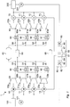
- Fig. 1 is a schematic configuration diagram of a compressed air energy storage (CAES) power generation device 1 according to an embodiment of the present invention.
- the CAES power generation device 1 stores power supplied from power generation facility 100 as compressed air (hereinafter, referred to as “charging”), generates power by using this compressed air as necessary, and supplies the power to a supply destination 200 such as a factory (hereinafter, referred to as “discharging”).
- the power generation facility 100 is, for example, equipment for power generation using renewable energies, such as wind power generation and solar power generation.
- the power generation facility 100 includes a power supply command transmitter 101.
- the power supply command transmitter 101 transmits a power supply command to the CAES power generation device 1.
- the power supply command is a command indicating an amount of power input to the CAES power generation device 1 from the power generation facility 100 to be used for energy storage (hereinafter, referred to as "input power").
- the power supply command transmitter 101 may be installed at a place other than the power generation facility 100 in a power system such as a substation.
- the supply destination 200 includes a discharge command transmitter 201.
- the discharge command transmitter 201 transmits a discharge command to the CAES power generation device 1.
- the discharge command is a command indicating an amount of power that the supply destination 200 requires from the CAES power generation device 1 (hereinafter, referred to as "output power").
- the CAES power generation device 1 includes motors 10 to 13 driven by the input power and compressors 20 to 23 driven by the motors 10 to 13, respectively, to compress air.
- the compressors 20 to 23 include suction ports 20a, 21a, 22a, and 23a, respectively, for taking in outside air, and discharge ports 20b, 21b, 22b, and 23b, respectively, for discharging compressed air compressed by the compressors 20 to 23.
- the compressors 20 to 23 are screw, turbo, scroll, reciprocating, or other types of compressors.
- the compressors 20 to 23 are preferably screw compressors. This is because screw compressors can generally control a rotational speed of a screw rotor, and can therefore flexibly respond to irregularly changing input power.
- the CAES power generation device 1 further includes an accumulator tank 40.
- the discharge ports 20b, 21b, 22b, and 23b are fluidly connected to the accumulator tank 40 via valves 30, 31, 32, and 33, respectively.
- the compressed air compressed by the compressors 20 to 23 and discharged from the discharge ports 20b, 21b, 22b, and 23b is stored in the accumulator tank 40.
- the CAES power generation device 1 further includes expanders 60 to 63 driven by the compressed air supplied from the accumulator tank 40 and generators 70 to 73 driven by the expanders 60 to 63, respectively, to supply the output power to the supply destination 200.
- the expanders 60 to 63 are fluidly connected to the accumulator tank 40, and include suction ports 60a, 61a, 62a, and 63a, respectively, for taking in the compressed air supplied from the accumulator 40 and discharge ports 60b, 61b, 62b, and 63b, respectively, for discharging air expanded by the expanders 60 to 63.
- Valves 50, 51, 52, and 53 for adjusting a flow rate of the compressed air supplied from the accumulator tank 40 are provided on an upstream side of the suction ports 60a, 61a, 62a, and 63a, respectively.
- the expanders 60 to 63 are screw, turbo, scroll, reciprocating, or other types of expanders, and are preferably screw expanders.
- the CAES power generation device 1 further includes a control device 80.
- the control device 80 is electrically connected to at least the motors 10 to 13, the valves 30 to 33, the valves 50 to 53, and the generators 70 to 73. Further, the control device 80 includes a power supply command receiver 82 that receives a power supply command transmitted from the power supply command transmitter 101 and a discharge command receiver 85 that receives a discharge command transmitted from the discharge command transmitter 201. Note that, in Fig. 1 , lines connecting the control device 80 to the valves 30 to 33 and the valves 50 to 53 are omitted in order to prevent the drawing from being complicated.
- the control device 80 includes, for example, hardware including a CPU, a RAM, a ROM, and the like and software mounted thereon.
- the CAES power generation device 1 includes first heat exchangers 90 to 93 for exchanging heat between the compressed air compressed by the respective compressors 20 to 23 and a heat medium.
- the CAES power generation device 1 further includes a high-temperature heat medium tank 99 that is fluidly connected to the first heat exchangers 90 to 93 and stores the heat medium supplied from the first heat exchangers 90 to 93.
- the CAES power generation device 1 further includes second heat exchangers 94 to 97 that are fluidly connected to the high-temperature heat medium tank 99 and exchange heat between the heat medium supplied from the high-temperature heat medium tank 99 and the compressed air supplied from the accumulator tank 40 to the respective expanders 60 to 63.
- the CAES power generation device 1 further includes a low-temperature heat medium tank 98 that is fluidly connected to the first heat exchangers 90 to 93 and the second heat exchangers 94 to 97 and stores the heat medium supplied from the second heat exchangers 94 to 97.
- a pump (not illustrated) for circulating the heat medium is provided on a heat medium path.
- the heat medium is, for example, water or oil, but is not limited thereto.
- the number of the first heat exchangers 90 to 93 and the second heat exchangers 94 to 97 is four in Fig. 1 , but is not limited thereto.
- CAES power generation device 1 including four motors, compressors, expanders, and generators has been described, but the number of motors, compressors, expanders, and generators is not limited thereto.
- one or more of the motors 10 to 13 are driven by input power, and the corresponding ones of the compressors 20 to 23 are driven to compress air.
- the number of motors 10 to 13 and compressors 20 to 23 to be driven (the number of driven compressors) is determined by a number-of-driven-compressors determination unit 83 of the control device 80 on the basis of a power supply command indicating an amount of the input power.
- a compression driver 84 of the control device 80 starts or stops the motors 10 to 13 until the number of the operating motors 10 to 13 becomes equal to the determined number of units to perform compression.
- Which of the motors 10 to 13 is to be started or stopped is determined on the basis of priority set in advance by a compressor priority setting unit 81 of the control device 80.
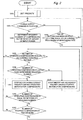
- Fig. 2 is a flowchart showing a specific example of a method of controlling the motors 10 to 13 and the compressors 20 to 23.
- the compressor priority setting unit 81 of the control device 80 sets priority to each of the motors 10 to 13 and each of the compressors 20 to 23. A method of determining the priority by the compressor priority setting unit 81 will be described later.
- step S202 the control device 80 determines whether or not the power supply command receiver 82 has received a power supply command transmitted from the power supply command transmitter 101.
- step S203 the process proceeds to step S203.
- step S204 the process proceeds to step S204.
- step S203 the control device 80 determines whether or not any of the motors 10 to 13 for the compressors 20 to 23 has been stopped for a time equal to or longer than a warm-up maintaining time T set in advance.
- the warm-up maintaining time T is, for example, ten minutes.
- step S204 the number-of-driven-compressors determination unit 83 of the control device 80 determines the required number of compressors 20 to 23 to operate on the basis of the amount of the input power indicated by the power supply command.
- step S205 the control device 80 determines whether or not the number of currently operating compressors 20 to 23 is equal to the required number determined in step S204.
- a result of step S205 is Yes, there is no need to change the number of compressors 20 to 23 (i.e., start the stopped compressors 20 to 23 or stop the operating compressors 20 to 23), and thus the process returns to step S202.
- the process proceeds to step S206.
- step S206 the control device 80 determines whether or not the number of currently operating compressors 20 to 23 is larger than the required number determined in step S204.
- the compression driver 84 of the control device 80 stops the motors 10 to 13 until the number of currently operating compressors 20 to 23 becomes equal to the required number determined in step S204.
- the compression driver 84 of the control device 80 stops one of the currently operating motors 10 to 13 for the compressors 20 to 23, i.e., for example, stops a motor having the lowest priority (step S207). Then, whether or not the number of currently operating compressors 20 to 23 is equal to the required number determined in step S204 is determined again (step S208).
- step S208 When a result of step S208 is No, the process returns to step S207. Steps S207 and S208 are repeated until the number of currently operating compressors 20 to 23 becomes equal to the required number determined in step S204. When the result of step S208 is Yes, the process proceeds to step S210.
- step S206 When the result of step S206 is No, the compression driver 84 of the control device 80 starts the currently stopped motors 10 to 13 until the number of currently operating compressors 20 to 23 becomes equal to the required number determined in step S204. Specifically, when the result of step S206 is No, the compression driver 84 of the control device 80 starts a motor having the highest priority among the currently stopped motors 10 to 13 (step S209). Then, the process returns to step S205.
- step S210 the control device 80 determines whether or not the number of currently stopped compressors 20 to 23 is two or more.
- a result of step S210 is Yes, i.e., when one of the motors 10 to 13 has been stopped (step S207) and the number of stopped motors is two or more, the process returns to step S201, and the priority is reset.
- the result of step S210 is No, the process returns to step S202, and the priority is not reset.
- FIG. 2 , 3 , 6 , and 7 include an infinite loop.
- those drawings show merely a main part of the flowcharts for describing the operation of the control device, and, in an actual control program, the process shifts to another control program after the priority is determined.
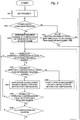
- Fig. 3 is a flowchart showing another specific example of the method of controlling the motors 10 to 13 and the compressors 20 to 23. Instead of step S210, whether or not all the compressors 20 to 23 are stopped may be determined in step S310. When a result of step S310 is Yes, i.e., when all the motors 10 to 13 are stopped, the process returns to step S301, and the priority is reset. When the result of step S310 is No, the process returns to step S302, and the priority is not reset.
- Priority numbers 1 to 4 are set to the motors 10 to 13, respectively. Generally, in a case where there are N motors, priority numbers 1 to N are set to the motors, respectively. "1" indicates the highest priority, and the priority becomes lower as the number increases. The same priority number is not set to a plurality of motors.
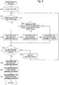
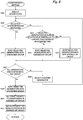
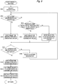
- Fig. 4 is a flowchart showing a specific example of the method of determining the priority of the motors 10 to 13 (steps S201 and S301) by the compressor priority setting unit 81 of the control device 80.
- the compressor priority setting unit 81 of the control device 80 sorts the motors 10 to 13 into one of an operating group, a warmed-up group, and a non-warmed-up group (steps S401 to S408).
- the motors 10 to 13 currently operating motors are sorted into the operating group (steps S402 and S404).
- motors that have been stopped for a time shorter than the warm-up maintaining time T are determined to be in a warmed-up state and are therefore sorted into the warmed-up group (steps S403 and S405).
- the other motors 10 to 13, i.e., the motors 10 to 13 that have been stopped for a time equal to or longer than the warm-up maintaining time T are sorted into the non-warmed-up group (step S406).
- the priority is set to the motors 10 to 13 sorted into the operating group (step S409).
- the priority to be set to the motors in the operating group is the same as the previous priority. That is, the priority of the motors in the operating group is maintained.
- first priority is set to the motors sorted into the warmed-up group among the motors 10 to 13 so that a motor whose elapsed time from stop is shorter has higher priority (step S410). However, the priority set to the motors in the operating group is excluded from the first priority.
- step S411 second priority is set to the motors sorted into the non-warmed-up group among the motors 10 to 13 so that a motor having a smaller total power consumption amount has higher priority.
- the second priority is lower than the first priority.
- the priority set to the motors in the operating group is excluded from the second priority.
- the second priority lower than the first priority is set to the motors 10 to 13 so that a motor having a smaller total power consumption amount has higher priority.
- the CAES power generation device 1 of the present invention among the motors 10 to 13 and the compressors 20 to 23 that have been stopped for a time shorter than the warm-up maintaining time T, the most recently operated motor and compressor are preferentially driven. Therefore, the motors 10 to 13 and the compressors 20 to 23 that can perform hot start more effectively are preferentially driven. This makes it possible to reduce energy and costs required for warming up. Meanwhile, among the motors that have been stopped for a time equal to or longer than the warm-up maintaining time T, a motor having a smaller total power consumption amount is preferentially driven. Thus, differences in operation time between all the motors 10 to 13 and between all the compressors 20 to 23 can be kept small, and total operation time of both the motors and compressors can be leveled.
- Leveling the operation frequency can level a life of each of the motors 10 to 13 and each of the compressors 20 to 23.
- Fig. 5 is a flowchart showing another specific example of the method of determining the priority of the motors 10 to 13 (steps S201 and S301) by the compressor priority setting unit 81 of the control device 80.
- whether or not the motors 10 to 13 have been warmed up is determined on the basis of temperatures detected by temperature sensors (not illustrated) attached to the first heat exchangers 90 to 93, the compressors 20 to 23, pipes thereof, or the like.
- step S403 whether or not the temperatures detected by the temperature sensors are equal to or higher than a threshold is determined in step S503.
- the process proceeds to step S505, and, when the result of the determination is No, the process proceeds to step S506.
- one or more of the expanders 60 to 63 are driven by compressed air supplied from the accumulator tank 40, and the corresponding ones of the generators 70 to 73 are driven to generate power.
- the number of the expanders 60 to 63 and the generators 70 to 73 to be driven (the number of driven generators) is determined by a number-of-driven-generators determination unit 86 of the control device 80 on the basis of a discharge command indicating an amount of the output power.
- a power generation driver 87 of the control device 80 starts or stops the expanders 60 to 63 and the generators 70 to 73 until the number of operating generators 70 to 73 becomes equal to the determined number of units to generate power.
- Which of the expanders 60 to 63 and the generators 70 to 73 is to be started or stopped is determined on the basis of priority set in advance by a generator priority setting unit 88 of the control device 80.
- FIG. 6 is a flowchart showing a specific example of a method of controlling the expanders 60 to 63 and the generators 70 to 73.
- the generator priority setting unit 88 of the control device 80 sets priority to each of the expanders 60 to 63 and each of the generators 70 to 73.
- a method of determining the priority by the generator priority setting unit 88 will be described later.
- step S602 the control device 80 determines whether or not the discharge command receiver 85 has received a discharge command transmitted from the discharge command transmitter 201.
- step S603 the process proceeds to step S604.
- step S603 the control device 80 determines whether or not any of the generators 70 to 73 has been stopped for a time equal to or longer than a warm-up maintaining time U set in advance.
- the warm-up maintaining time U is, for example, ten minutes.
- step S604 the number-of-driven-generators determination unit 86 of the control device 80 determines the required number of generators 70 to 73 to operate on the basis of the amount of the output power indicated by the discharge command.
- step S605 the control device 80 determines whether or not the number of currently operating generators 70 to 73 is equal to the required number determined in step S604.
- step S605 determines whether or not the number of currently operating generators 70 to 73 is equal to the required number determined in step S604.
- step S606 the control device 80 determines whether or not the number of currently operating generators 70 to 73 is larger than the required number determined in step S604.
- the power generation driver 87 of the control device 80 stops the expanders 60 to 63 and the generators 70 to 73 until the number of currently operating generators 70 to 73 becomes equal to the required number determined in step S604.
- the power generation driver 87 of the control device 80 stops one of the currently operating generators 70 to 73, i.e., for example, stops a generator having the lowest priority (step S607).
- step S608 determines whether or not the number of currently operating generators 70 to 73 is equal to the required number determined in step S604 is determined again (step S608).
- step S608 determines whether or not the number of currently operating generators 70 to 73 is equal to the required number determined in step S604 is determined again (step S608).
- step S608 determines whether or not the number of currently operating generators 70 to 73 is equal to the required number determined in step S604.
- step S606 the power generation driver 87 of the control device 80 starts the currently stopped generators 70 to 73 until the number of currently operating generators 70 to 73 becomes equal to the required number determined in step S604. Specifically, when the result of step S606 is No, the power generation driver 87 of the control device 80 starts a generator having the highest priority among the currently stopped generators 70 to 73 (step S609). Then, the process returns to step S605.
- step S610 the control device 80 determines whether or not the number of currently stopped generators 70 to 73 is two or more.
- a result of step S610 is Yes, i.e., when one of the generators 70 to 73 is stopped (step S607) and the number of stopped generators is two or more, the process returns to step S601, and the priority is reset.
- the result of step S610 is No, the process returns to step S602, and the priority is not reset.
- Fig. 7 is a flowchart showing another specific example of the method of controlling the expanders 60 to 63 and the generators 70 to 73.
- step S610 whether or not all the generators 70 to 73 are stopped may be determined in step S710.
- a result of step S710 is Yes, i.e., when all the generators 70 to 73 are stopped, the process returns to step S701, and the priority is reset.
- the result of step S710 is No, the process returns to step S702, and the priority is not reset.
- Priority numbers 1 to 4 are set to the generators 70 to 73, respectively. Generally, in a case where there are M generators, priority numbers 1 to M are set to the generators, respectively. The same priority number is not set to a plurality of generators.
- Fig. 8 is a flowchart showing a specific example of the method of determining the priority of the generators 70 to 73 (steps S601 and S701) by the generator priority setting unit 88 of the control device 80.
- the generator priority setting unit 88 of the control device 80 sorts the generators 70 to 73 into one of an operating group, a warmed-up group, and a non-warmed-up group (steps S801 to S808).
- the generators 70 to 73 currently operating generators are sorted into the operating group (steps S802 and S804).
- generators that have been stopped for a time shorter than the warm-up maintaining time U are determined to be in a warmed-up state and are therefore sorted into the warmed-up group (steps S803 and S805).
- the other generators 70 to 73 i.e., the generators 70 to 73 that have been stopped for a time equal to or longer than the warm-up maintaining time U are sorted into the non-warmed-up group (step S806).
- the priority is set to the generators 70 to 73 sorted into the operating group (step S809).
- the priority to be set to the generators in the operating group is the same as the previous priority. That is, the priority of the generators in the operating group is maintained.
- first priority is set to the generators sorted into the warmed-up group among the generators 70 to 73 so that a generator whose elapsed time from stop is shorter has higher priority (step S810).
- the priority set to the generators in the operating group is excluded from the first priority.
- step S811 second priority is set to the generators sorted into the non-warmed-up group among the generators 70 to 73 so that a generator having a smaller total power generation amount has higher priority.
- the second priority is lower than the first priority.
- the priority set to the generators in the operating group is excluded from the second priority.
- the second priority lower than the first priority is set to the generators 70 to 73 so that a generator having a smaller total power generation amount has higher priority.
- the expanders 60 to 63 and the generators 70 to 73 that have been stopped for a time shorter than the warm-up maintaining time U the most recently operated expander and generator are preferentially driven. Therefore, the expanders 60 to 63 and the generators 70 to 73 that can perform hot start more effectively are preferentially driven. This makes it possible to reduce energy and costs required for warming up. Meanwhile, among the generators that have been stopped for a time equal to or longer than the warm-up maintaining time U, a generator having a smaller total power generation amount is preferentially driven. Thus, differences in operation time between all the generators 70 to 73 and between all the expanders 60 to 63 can be kept small, and total operation time of both the generators and expanders can be leveled.
- Fig. 9 is a flowchart showing another specific example of the method of determining the priority of the generators 70 to 73 (steps S601 and S701) by the generator priority setting unit 88 of the control device 80.
- whether or not the generators 70 to 73 have been warmed up is determined on the basis of temperatures detected by temperature sensors (not illustrated) attached to the second heat exchangers 94 to 97, the expanders 60 to 63, pipes thereof, or the like.
- step S903 instead of step S803, whether or not the temperatures detected by the temperature sensors are equal to or higher than a threshold is determined in step S903.
- the process proceeds to step S905, and, when the result of the determination is No, the process proceeds to step S906.
- the power generation facility 100 is assumed to fluctuate by using renewable energies, but a power supply is not necessarily need to fluctuate.
- the power generation facility may receive a general stable commercial power supply as input and respond to fluctuation of the supply destination 200. In this case, contract power of the commercial power supply can be reduced by cutting a peak of the supply destination 200.
- the compressors 20 to 23 and the motors 10 to 13 and the expanders 60 to 63 and the generators 70 to 73 are physically different.
- the compressors 20 to 23 and the expanders 60 to 63 of this embodiment are the same.
- the compressors may also serve as the expanders, and the motors may also serve as the generators.
Landscapes
- Engineering & Computer Science (AREA)
- Chemical & Material Sciences (AREA)
- Combustion & Propulsion (AREA)
- Mechanical Engineering (AREA)
- General Engineering & Computer Science (AREA)
- Power Engineering (AREA)
- Physics & Mathematics (AREA)
- Fluid Mechanics (AREA)
- Control Of Turbines (AREA)
- Control Of Eletrric Generators (AREA)
- Control Of Positive-Displacement Pumps (AREA)
- Engine Equipment That Uses Special Cycles (AREA)
- Supply And Distribution Of Alternating Current (AREA)
Applications Claiming Priority (2)
| Application Number | Priority Date | Filing Date | Title |
|---|---|---|---|
| JP2018001296A JP6910969B2 (ja) | 2018-01-09 | 2018-01-09 | 圧縮空気貯蔵発電装置および圧縮空気貯蔵発電方法 |
| PCT/JP2018/045633 WO2019138764A1 (ja) | 2018-01-09 | 2018-12-12 | 圧縮空気貯蔵発電装置および圧縮空気貯蔵発電方法 |
Publications (2)
| Publication Number | Publication Date |
|---|---|
| EP3739174A1 true EP3739174A1 (de) | 2020-11-18 |
| EP3739174A4 EP3739174A4 (de) | 2021-10-13 |
Family
ID=67218467
Family Applications (1)
| Application Number | Title | Priority Date | Filing Date |
|---|---|---|---|
| EP18900459.1A Withdrawn EP3739174A4 (de) | 2018-01-09 | 2018-12-12 | Vorrichtung zur erzeugung von strom aus druckluftenergiespeicher und verfahren zur erzeugung von strom aus druckluftenergiespeicher |
Country Status (6)
| Country | Link |
|---|---|
| US (1) | US20210003031A1 (de) |
| EP (1) | EP3739174A4 (de) |
| JP (1) | JP6910969B2 (de) |
| CN (1) | CN111566319A (de) |
| CA (1) | CA3086892A1 (de) |
| WO (1) | WO2019138764A1 (de) |
Families Citing this family (2)
| Publication number | Priority date | Publication date | Assignee | Title |
|---|---|---|---|---|
| JP6889604B2 (ja) * | 2017-04-26 | 2021-06-18 | 株式会社神戸製鋼所 | 圧縮空気貯蔵発電装置 |
| CN115632488B (zh) * | 2022-12-21 | 2023-03-31 | 势加透博(成都)科技有限公司 | 一种级联型储能系统及储能方法 |
Family Cites Families (10)
| Publication number | Priority date | Publication date | Assignee | Title |
|---|---|---|---|---|
| US4043120A (en) * | 1973-10-25 | 1977-08-23 | Brown Boveri-Sulzer Turbomaschinen Ag | Starting arrangement for combined air and gas turbine power plant |
| DE2538756C2 (de) * | 1975-08-30 | 1983-11-24 | BBC Aktiengesellschaft Brown, Boveri & Cie., 5401 Baden, Aargau | Verfahren zum Anfahren einer Gasturbinenanlage mit Luftspeicher |
| JP2828547B2 (ja) * | 1992-08-14 | 1998-11-25 | 大阪瓦斯株式会社 | 熱源機の台数制御装置 |
| CN100394665C (zh) * | 2001-02-16 | 2008-06-11 | 洋马株式会社 | 具有由发动机驱动的发电机的电力系统 |
| JP3764056B2 (ja) * | 2001-02-16 | 2006-04-05 | ヤンマー株式会社 | パワーコンディショナの運転制御装置とその運転制御方法 |
| DE10236501A1 (de) * | 2001-08-17 | 2003-04-03 | Alstom Switzerland Ltd | Startverfahren für eine Kraftwerksanlage |
| JP5396766B2 (ja) * | 2008-07-29 | 2014-01-22 | 株式会社明電舎 | 分散電源系統の制御方式 |
| JP2016082740A (ja) * | 2014-10-17 | 2016-05-16 | 三菱重工業株式会社 | 発電設備の運転制御方法及び運転制御装置 |
| JP6373794B2 (ja) * | 2015-05-08 | 2018-08-15 | 株式会社神戸製鋼所 | 圧縮空気貯蔵発電装置及び圧縮空気貯蔵発電方法 |
| JP6387325B2 (ja) | 2015-05-11 | 2018-09-05 | 株式会社神戸製鋼所 | 圧縮空気貯蔵発電装置 |
-
2018
- 2018-01-09 JP JP2018001296A patent/JP6910969B2/ja not_active Expired - Fee Related
- 2018-12-12 WO PCT/JP2018/045633 patent/WO2019138764A1/ja not_active Ceased
- 2018-12-12 CA CA3086892A patent/CA3086892A1/en not_active Abandoned
- 2018-12-12 CN CN201880085896.4A patent/CN111566319A/zh active Pending
- 2018-12-12 US US16/955,733 patent/US20210003031A1/en not_active Abandoned
- 2018-12-12 EP EP18900459.1A patent/EP3739174A4/de not_active Withdrawn
Also Published As
| Publication number | Publication date |
|---|---|
| US20210003031A1 (en) | 2021-01-07 |
| JP2019120208A (ja) | 2019-07-22 |
| CA3086892A1 (en) | 2019-07-18 |
| JP6910969B2 (ja) | 2021-07-28 |
| EP3739174A4 (de) | 2021-10-13 |
| CN111566319A (zh) | 2020-08-21 |
| WO2019138764A1 (ja) | 2019-07-18 |
Similar Documents
| Publication | Publication Date | Title |
|---|---|---|
| US10655505B2 (en) | Compressed air energy storage and power generation device and compressed air energy storage and power generation method | |
| EP3575576B1 (de) | Stromerzeugungsverfahren mit druckluftspeicherung und stromerzeugungsvorrichtung mit druckluftspeicherung | |
| US10746097B2 (en) | Compressed air energy storage power generation device and compressed air energy storage power generation method | |
| US10892642B2 (en) | Compressed air energy storage power generation apparatus and compressed air energy storage power generation method | |
| US10794279B2 (en) | Compressed air energy storage power generation device | |
| US10954852B2 (en) | Compressed air energy storage power generation device | |
| JP2017083082A (ja) | ヒートポンプ | |
| WO2013020034A2 (en) | Variable frequency generator power supply for centrifugal chillers | |
| EP3739174A1 (de) | Vorrichtung zur erzeugung von strom aus druckluftenergiespeicher und verfahren zur erzeugung von strom aus druckluftenergiespeicher | |
| EP3663561A1 (de) | Druckluftspeicherkraftwerk | |
| US10526969B2 (en) | Compressed air energy storage power generation device and compressed air energy storage power generation method | |
| JP2017141992A (ja) | 圧縮空気貯蔵発電装置および圧縮空気貯蔵発電方法 | |
| JP2019027385A (ja) | 圧縮空気貯蔵発電装置及び方法 | |
| CN102620515B (zh) | 包括制冷装置和控制器的系统 | |
| JP2019174105A (ja) | ヒートポンプ | |
| Αξαόπουλος et al. | Design and experimental performance of a PV Ice-maker without battery | |
| Αξαόπουλος et al. | Design and performance of a multiple compressor solar ice-maker |
Legal Events
| Date | Code | Title | Description |
|---|---|---|---|
| STAA | Information on the status of an ep patent application or granted ep patent |
Free format text: STATUS: THE INTERNATIONAL PUBLICATION HAS BEEN MADE |
|
| PUAI | Public reference made under article 153(3) epc to a published international application that has entered the european phase |
Free format text: ORIGINAL CODE: 0009012 |
|
| STAA | Information on the status of an ep patent application or granted ep patent |
Free format text: STATUS: REQUEST FOR EXAMINATION WAS MADE |
|
| 17P | Request for examination filed |
Effective date: 20200701 |
|
| AK | Designated contracting states |
Kind code of ref document: A1 Designated state(s): AL AT BE BG CH CY CZ DE DK EE ES FI FR GB GR HR HU IE IS IT LI LT LU LV MC MK MT NL NO PL PT RO RS SE SI SK SM TR |
|
| AX | Request for extension of the european patent |
Extension state: BA ME |
|
| DAV | Request for validation of the european patent (deleted) | ||
| DAX | Request for extension of the european patent (deleted) | ||
| A4 | Supplementary search report drawn up and despatched |
Effective date: 20210913 |
|
| RIC1 | Information provided on ipc code assigned before grant |
Ipc: F02C 9/42 20060101ALI20210907BHEP Ipc: F02C 7/26 20060101ALI20210907BHEP Ipc: F02C 6/16 20060101ALI20210907BHEP Ipc: H02P 9/04 20060101ALI20210907BHEP Ipc: F02C 1/02 20060101ALI20210907BHEP Ipc: F01D 17/00 20060101ALI20210907BHEP Ipc: F01D 19/00 20060101AFI20210907BHEP |
|
| STAA | Information on the status of an ep patent application or granted ep patent |
Free format text: STATUS: THE APPLICATION IS DEEMED TO BE WITHDRAWN |
|
| 18D | Application deemed to be withdrawn |
Effective date: 20220412 |