EP3739176A1 - Centrale électrique et procédé de d'épuration de l'eau pour un cycle eau/vapeur à passage unique d'une centrale électrique - Google Patents
Centrale électrique et procédé de d'épuration de l'eau pour un cycle eau/vapeur à passage unique d'une centrale électrique Download PDFInfo
- Publication number
- EP3739176A1 EP3739176A1 EP19174635.3A EP19174635A EP3739176A1 EP 3739176 A1 EP3739176 A1 EP 3739176A1 EP 19174635 A EP19174635 A EP 19174635A EP 3739176 A1 EP3739176 A1 EP 3739176A1
- Authority
- EP
- European Patent Office
- Prior art keywords
- economizer
- water
- steam
- hotwell
- power plant
- Prior art date
- Legal status (The legal status is an assumption and is not a legal conclusion. Google has not performed a legal analysis and makes no representation as to the accuracy of the status listed.)
- Withdrawn
Links
- XLYOFNOQVPJJNP-UHFFFAOYSA-N water Substances O XLYOFNOQVPJJNP-UHFFFAOYSA-N 0.000 title claims abstract description 59
- 238000000034 method Methods 0.000 title claims abstract description 12
- 238000004140 cleaning Methods 0.000 title description 4
- 238000005498 polishing Methods 0.000 claims abstract description 28
- 239000012530 fluid Substances 0.000 claims abstract description 20
- 238000010438 heat treatment Methods 0.000 claims abstract description 12
- 238000012546 transfer Methods 0.000 claims abstract description 3
- XEEYBQQBJWHFJM-UHFFFAOYSA-N Iron Chemical compound [Fe] XEEYBQQBJWHFJM-UHFFFAOYSA-N 0.000 claims description 9
- 229910052742 iron Inorganic materials 0.000 claims description 5
- 238000005086 pumping Methods 0.000 claims description 2
- 239000007789 gas Substances 0.000 description 14
- 238000011084 recovery Methods 0.000 description 13
- 239000012223 aqueous fraction Substances 0.000 description 3
- 238000013461 design Methods 0.000 description 3
- 238000012986 modification Methods 0.000 description 2
- 230000004048 modification Effects 0.000 description 2
- 230000008646 thermal stress Effects 0.000 description 2
- 238000002485 combustion reaction Methods 0.000 description 1
- 230000001419 dependent effect Effects 0.000 description 1
- 238000011161 development Methods 0.000 description 1
- 230000018109 developmental process Effects 0.000 description 1
- 238000010586 diagram Methods 0.000 description 1
- 239000002737 fuel gas Substances 0.000 description 1
- 239000012535 impurity Substances 0.000 description 1
- 150000002505 iron Chemical class 0.000 description 1
- 239000000203 mixture Substances 0.000 description 1
- 238000002360 preparation method Methods 0.000 description 1
- 230000035939 shock Effects 0.000 description 1
Images

Classifications
-
- F—MECHANICAL ENGINEERING; LIGHTING; HEATING; WEAPONS; BLASTING
- F01—MACHINES OR ENGINES IN GENERAL; ENGINE PLANTS IN GENERAL; STEAM ENGINES
- F01K—STEAM ENGINE PLANTS; STEAM ACCUMULATORS; ENGINE PLANTS NOT OTHERWISE PROVIDED FOR; ENGINES USING SPECIAL WORKING FLUIDS OR CYCLES
- F01K13/00—General layout or general methods of operation of complete plants
- F01K13/02—Controlling, e.g. stopping or starting
-
- F—MECHANICAL ENGINEERING; LIGHTING; HEATING; WEAPONS; BLASTING
- F01—MACHINES OR ENGINES IN GENERAL; ENGINE PLANTS IN GENERAL; STEAM ENGINES
- F01D—NON-POSITIVE DISPLACEMENT MACHINES OR ENGINES, e.g. STEAM TURBINES
- F01D19/00—Starting of machines or engines; Regulating, controlling, or safety means in connection therewith
-
- F—MECHANICAL ENGINEERING; LIGHTING; HEATING; WEAPONS; BLASTING
- F01—MACHINES OR ENGINES IN GENERAL; ENGINE PLANTS IN GENERAL; STEAM ENGINES
- F01D—NON-POSITIVE DISPLACEMENT MACHINES OR ENGINES, e.g. STEAM TURBINES
- F01D25/00—Component parts, details, or accessories, not provided for in, or of interest apart from, other groups
- F01D25/32—Collecting of condensation water; Drainage ; Removing solid particles
-
- F—MECHANICAL ENGINEERING; LIGHTING; HEATING; WEAPONS; BLASTING
- F01—MACHINES OR ENGINES IN GENERAL; ENGINE PLANTS IN GENERAL; STEAM ENGINES
- F01K—STEAM ENGINE PLANTS; STEAM ACCUMULATORS; ENGINE PLANTS NOT OTHERWISE PROVIDED FOR; ENGINES USING SPECIAL WORKING FLUIDS OR CYCLES
- F01K11/00—Plants characterised by the engines being structurally combined with boilers or condensers
- F01K11/02—Plants characterised by the engines being structurally combined with boilers or condensers the engines being turbines
-
- F—MECHANICAL ENGINEERING; LIGHTING; HEATING; WEAPONS; BLASTING
- F01—MACHINES OR ENGINES IN GENERAL; ENGINE PLANTS IN GENERAL; STEAM ENGINES
- F01K—STEAM ENGINE PLANTS; STEAM ACCUMULATORS; ENGINE PLANTS NOT OTHERWISE PROVIDED FOR; ENGINES USING SPECIAL WORKING FLUIDS OR CYCLES
- F01K23/00—Plants characterised by more than one engine delivering power external to the plant, the engines being driven by different fluids
- F01K23/02—Plants characterised by more than one engine delivering power external to the plant, the engines being driven by different fluids the engine cycles being thermally coupled
- F01K23/06—Plants characterised by more than one engine delivering power external to the plant, the engines being driven by different fluids the engine cycles being thermally coupled combustion heat from one cycle heating the fluid in another cycle
- F01K23/10—Plants characterised by more than one engine delivering power external to the plant, the engines being driven by different fluids the engine cycles being thermally coupled combustion heat from one cycle heating the fluid in another cycle with exhaust fluid of one cycle heating the fluid in another cycle
-
- F—MECHANICAL ENGINEERING; LIGHTING; HEATING; WEAPONS; BLASTING
- F22—STEAM GENERATION
- F22B—METHODS OF STEAM GENERATION; STEAM BOILERS
- F22B35/00—Control systems for steam boilers
- F22B35/06—Control systems for steam boilers for steam boilers of forced-flow type
- F22B35/10—Control systems for steam boilers for steam boilers of forced-flow type of once-through type
-
- F—MECHANICAL ENGINEERING; LIGHTING; HEATING; WEAPONS; BLASTING
- F22—STEAM GENERATION
- F22B—METHODS OF STEAM GENERATION; STEAM BOILERS
- F22B37/00—Component parts or details of steam boilers
- F22B37/02—Component parts or details of steam boilers applicable to more than one kind or type of steam boiler
- F22B37/26—Steam-separating arrangements
- F22B37/265—Apparatus for washing and purifying steam
-
- F—MECHANICAL ENGINEERING; LIGHTING; HEATING; WEAPONS; BLASTING
- F22—STEAM GENERATION
- F22D—PREHEATING, OR ACCUMULATING PREHEATED, FEED-WATER FOR STEAM GENERATION; FEED-WATER SUPPLY FOR STEAM GENERATION; CONTROLLING WATER LEVEL FOR STEAM GENERATION; AUXILIARY DEVICES FOR PROMOTING WATER CIRCULATION WITHIN STEAM BOILERS
- F22D11/00—Feed-water supply not provided for in other main groups
- F22D11/006—Arrangements of feedwater cleaning with a boiler
-
- F—MECHANICAL ENGINEERING; LIGHTING; HEATING; WEAPONS; BLASTING
- F05—INDEXING SCHEMES RELATING TO ENGINES OR PUMPS IN VARIOUS SUBCLASSES OF CLASSES F01-F04
- F05D—INDEXING SCHEME FOR ASPECTS RELATING TO NON-POSITIVE-DISPLACEMENT MACHINES OR ENGINES, GAS-TURBINES OR JET-PROPULSION PLANTS
- F05D2220/00—Application
- F05D2220/30—Application in turbines
- F05D2220/31—Application in turbines in steam turbines
-
- F—MECHANICAL ENGINEERING; LIGHTING; HEATING; WEAPONS; BLASTING
- F05—INDEXING SCHEMES RELATING TO ENGINES OR PUMPS IN VARIOUS SUBCLASSES OF CLASSES F01-F04
- F05D—INDEXING SCHEME FOR ASPECTS RELATING TO NON-POSITIVE-DISPLACEMENT MACHINES OR ENGINES, GAS-TURBINES OR JET-PROPULSION PLANTS
- F05D2270/00—Control
- F05D2270/30—Control parameters, e.g. input parameters
-
- Y—GENERAL TAGGING OF NEW TECHNOLOGICAL DEVELOPMENTS; GENERAL TAGGING OF CROSS-SECTIONAL TECHNOLOGIES SPANNING OVER SEVERAL SECTIONS OF THE IPC; TECHNICAL SUBJECTS COVERED BY FORMER USPC CROSS-REFERENCE ART COLLECTIONS [XRACs] AND DIGESTS
- Y02—TECHNOLOGIES OR APPLICATIONS FOR MITIGATION OR ADAPTATION AGAINST CLIMATE CHANGE
- Y02E—REDUCTION OF GREENHOUSE GAS [GHG] EMISSIONS, RELATED TO ENERGY GENERATION, TRANSMISSION OR DISTRIBUTION
- Y02E20/00—Combustion technologies with mitigation potential
- Y02E20/16—Combined cycle power plant [CCPP], or combined cycle gas turbine [CCGT]
Definitions
- the present invention relates to a power plant and a water cleaning method for a once-through water-steam cycle of a power plant.
- the invention relates to water cleaning during start-up of the power plant.
- the iron content in the water can be too high, especially when the water has been standing still in the heat recovery steam generator for a while.
- This iron needs to be removed from the water before it is all turned into steam, to avoid damage in equipment downstream of the evaporator part in the heat recovery steam generator.
- Known combined cycle power plants with a once-through steam generation system typically comprise a separator arranged in the heat recovery steam generator and installed to separate the water fraction (containing the dissolved iron) and to take that water fraction out of the steam flow. The separated water fraction is then thrown away or can be further cleaned.
- a typical disadvantage of such an arrangement is that a separator requires extra connections, piping, and a support structure. This makes the heat recovery steam generator heavier, more complex and more voluminous.
- a further goal of the invention is to provide a water cleaning method for a power plant with water-steam-cycle.
- a power plant with a water-steam-cycle comprising a steam generator with a plurality of heating surfaces configured to carry a fluid and to transfer heat to said fluid, the plurality of heating surfaces comprising an economizer for preheating said fluid and an evaporator for producing steam, the evaporator being fluidly connected to the economizer.
- the power plant further comprises a steam turbine that is configured to receive the steam produced in the steam generator to generate power output; the power plant also comprises a condenser configured to condense steam from the steam turbine, the condenser comprising a hotwell as collection container for condensed steam or water.
- the power plant also comprises a polishing plant that is arranged fluidly between the hotwell of the condenser and the economizer.
- a drain line interconnects an outlet of the economizer and the hotwell of the condenser and a fluid line interconnects the outlet of the economizer and the evaporator.
- the invention is characterized in that the fluid line comprises means to hold back water in the economizer.
- the water contained in the economizer (the rest of the steam generator is empty during stand-still) is pumped through the drain to the hotwell, where it is diluted and the water from there is led at least partly through the polishing plant and cleaned.
- the steam generator is ready to start-up.
- water from the hotwell is not of the correct quality, water can be circulated over this drain and led through the polishing plant until it is clean enough for starting the steam generator.
- an outlet header for collecting preheated feedwater and for evenly spreading this preheated feedwater over the evaporator tubes is arranged. From this outlet header the drain line to the hotwell and the fluid line to the evaporator branch off.
- tubes at the outlet header of the economizer are bent upwards to create a syphon which preferably reaches till above the inlet header of the economizer, even more preferably as high as possible.
- a syphon carries out its function passively without any moveable components and its thermal stability is identical to the other tubes in the steam generator.
- a part of the preheated water may get into evaporator and superheater tubes. This fluid would have to be drained afterwards.
- the means to hold back water is a valve. With the valve closed, there will be no preheated water getting into downstream arranged tubes of the evaporator. But an active control of the valve will require more effort than the solution with a syphon.
- a polishing plant is arranged fluidly between the hotwell of the condenser and the economizer and a capacity of the polishing plant in parallel flow to a main condensate line is less than 100% of an amount of water supplied to the economizer at base load.
- the invention is applicable to all power plants with a water-steam-cycle. It is particularly advantageous when the heat source for the steam generator is a gas turbine.
- the method according to the present invention is characterized by the step(s) of
- water is continuously drained from the economizer, led at least partly through the polishing plant and supplied to the economizer in case water from the hotwell and the polishing plant is not of a required quality, until it is clean enough for starting the steam generator.
- water contained in the economizer is drained by pumping boiler feedwater into the economizer and where applicable by opening a drain at an economizer outlet header.
- water getting over syphon tubes at an economizer outlet into evaporator and superheater tubes is drained by a drip leg at a heat recovery steam generator outlet and led to the hotwell.
- An important advantage of the power plant according to the present invention is the implementation of a mechanical arrangement such that only the economizer contains water at standstill, and that an intermediate loop can be formed to circulate the water over the polishing plant until it is clean.
- the size of the polishing plant can be kept small. Another way to clean up the water that is used, is to install a polishing plant of 100% capacity, and all the water is led through this polishing plant. While filling the steam generator, just prior to start-up, it is with clean water. With this new system the steam generator doesn't need to be drained and refilled, and the polishing plant can be kept at its regular size of about 50%.
- Figure 1 illustrates a schematic diagram of a power plant 1 according to the invention.
- the power plant 1 may be a combined cycle power plant 22, including a gas turbine 18.
- the gas turbine 18 generates power output from combustion of a fuel gas and air mixture.
- the gas turbine 18 is connected to a first generator 23.
- the gas turbine 18 produces exhaust gas at an exit of the gas turbine 18.
- a combined cycle power plant 22 includes a steam generator 2, or more specifically a heat recovery steam generator 24, which is located downstream of the gas turbine 18.
- the heat recovery steam generator 24 receives the exhaust gas from the gas turbine 18.
- the heat recovery steam generator 24 comprises a plurality of heating surfaces 3.
- a heat recovery steam generator 24 usually includes multiple pressure steam systems.
- the heating surfaces of the heat recovery steam generator 24 belong to only one pressure system and comprise a superheater 19, an evaporator 5 and an economizer 4.
- the exhaust gas flows across the heating surfaces 3 to produce steam by extracting energy from the exhaust gas.
- a combined cycle power plant 22 also includes a steam turbine 6 that is configured to receive the steam produced in the heat recovery steam generator 24 to generate power output.
- the combined cycle power plant 22 illustrated in Figure 1 is in a multi-shaft configuration.
- the steam turbine 6 is connected to a second generator 25.
- the invention is of course also applicable to a single shaft configuration.
- a condenser 7 is located at an exit of the steam turbine 6 and is configured to condense steam from the steam turbine 6, the condenser 7 comprising a hotwell 8 as collection container for condensed steam or water.
- the power plant 1 of Figure 1 also shows a main condensate line 17 interconnecting hotwell 8 and economizer 4.
- a polishing plant 9 is arranged fluidly between the hotwell 8 of the condenser 7 and the economizer 4. The polishing plant 9 removes impurities, that could cause damage to the steam generator 2 or the steam turbine, from the condensate.
- Condenser 7 (+ polishing plant 9), steam generator 2 and steam turbine 6 form a water-steam cycle.
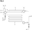
- FIG. 2 shows a more detailed view of the steam generator 2 for economizer 4 and evaporator 5, where a drain line 10 interconnects an outlet header 14 arranged at an outlet 11 of the economizer 4 and the hotwell 8 of the condenser 7 and where a fluid line 12 interconnects the outlet 11 of the economizer 4 and the evaporator 5.
- the fluid line 12 comprises means 13 to hold back water in the economizer 4 during standstill.
- the means 13 to hold back water is a syphon 15 that reaches above an inlet header 16 of the economizer 4.
- a drip leg 20 In case water is getting over the syphon 15 at the economizer outlet 11 into evaporator 5 and superheater 19 tubes, it is drained by a drip leg 20 at a heat recovery steam generator outlet 21 and led to the hotwell 8.
Landscapes
- Engineering & Computer Science (AREA)
- Mechanical Engineering (AREA)
- General Engineering & Computer Science (AREA)
- Chemical & Material Sciences (AREA)
- Combustion & Propulsion (AREA)
- Physics & Mathematics (AREA)
- Thermal Sciences (AREA)
- Water Supply & Treatment (AREA)
- Engine Equipment That Uses Special Cycles (AREA)
- Heat Treatment Of Water, Waste Water Or Sewage (AREA)
- Physical Water Treatments (AREA)
Priority Applications (9)
| Application Number | Priority Date | Filing Date | Title |
|---|---|---|---|
| EP19174635.3A EP3739176A1 (fr) | 2019-05-15 | 2019-05-15 | Centrale électrique et procédé de d'épuration de l'eau pour un cycle eau/vapeur à passage unique d'une centrale électrique |
| KR1020217040552A KR102563169B1 (ko) | 2019-05-15 | 2020-02-17 | 발전소 및 발전소의 관류 물/증기 사이클을 위한 물 정화 방법 |
| CN202080035399.0A CN113840977A (zh) | 2019-05-15 | 2020-02-17 | 动力设备以及用于动力设备的直流水/蒸汽循环的水清洁方法 |
| EP20710041.3A EP3942160B1 (fr) | 2019-05-15 | 2020-02-17 | Centrale électrique et procédé de d'épuration de l'eau pour un cycle eau/vapeur à passage unique d'une centrale électrique |
| US17/607,884 US20220220859A1 (en) | 2019-05-15 | 2020-02-17 | Power plant and water cleaning method for a once-through water/steam cycle of a power plant |
| CA3140253A CA3140253C (fr) | 2019-05-15 | 2020-02-17 | Centrale electrique et procede de nettoyage d'eau pour un cycle eau/vapeur a passage unique d'une centrale electrique |
| PCT/EP2020/054074 WO2020229001A1 (fr) | 2019-05-15 | 2020-02-17 | Centrale électrique et procédé de nettoyage d'eau pour un cycle eau/vapeur à passage unique d'une centrale électrique |
| ES20710041T ES2950804T3 (es) | 2019-05-15 | 2020-02-17 | Central eléctrica y procedimiento de depuración de agua para un ciclo de agua / vapor de un solo paso de una central eléctrica |
| JP2021566590A JP2022533575A (ja) | 2019-05-15 | 2020-02-17 | 発電装置と、発電装置の貫流型の水と蒸気のサイクル用の水浄化方法 |
Applications Claiming Priority (1)
| Application Number | Priority Date | Filing Date | Title |
|---|---|---|---|
| EP19174635.3A EP3739176A1 (fr) | 2019-05-15 | 2019-05-15 | Centrale électrique et procédé de d'épuration de l'eau pour un cycle eau/vapeur à passage unique d'une centrale électrique |
Publications (1)
| Publication Number | Publication Date |
|---|---|
| EP3739176A1 true EP3739176A1 (fr) | 2020-11-18 |
Family
ID=66554260
Family Applications (2)
| Application Number | Title | Priority Date | Filing Date |
|---|---|---|---|
| EP19174635.3A Withdrawn EP3739176A1 (fr) | 2019-05-15 | 2019-05-15 | Centrale électrique et procédé de d'épuration de l'eau pour un cycle eau/vapeur à passage unique d'une centrale électrique |
| EP20710041.3A Active EP3942160B1 (fr) | 2019-05-15 | 2020-02-17 | Centrale électrique et procédé de d'épuration de l'eau pour un cycle eau/vapeur à passage unique d'une centrale électrique |
Family Applications After (1)
| Application Number | Title | Priority Date | Filing Date |
|---|---|---|---|
| EP20710041.3A Active EP3942160B1 (fr) | 2019-05-15 | 2020-02-17 | Centrale électrique et procédé de d'épuration de l'eau pour un cycle eau/vapeur à passage unique d'une centrale électrique |
Country Status (8)
| Country | Link |
|---|---|
| US (1) | US20220220859A1 (fr) |
| EP (2) | EP3739176A1 (fr) |
| JP (1) | JP2022533575A (fr) |
| KR (1) | KR102563169B1 (fr) |
| CN (1) | CN113840977A (fr) |
| CA (1) | CA3140253C (fr) |
| ES (1) | ES2950804T3 (fr) |
| WO (1) | WO2020229001A1 (fr) |
Citations (8)
| Publication number | Priority date | Publication date | Assignee | Title |
|---|---|---|---|---|
| FR2509901A1 (fr) * | 1981-07-16 | 1983-01-21 | Kraftwerk Union Ag | Centrale nucleaire et procede pour l'exploitation d'une telle centrale |
| JPS58190690A (ja) * | 1982-04-30 | 1983-11-07 | Toshiba Corp | サイドストリ−ム式復水浄化系統を有する発電プラント |
| JPS58222905A (ja) * | 1982-06-22 | 1983-12-24 | Toshiba Corp | 給復水系再循環システム |
| JPS60101204A (ja) * | 1983-11-08 | 1985-06-05 | Mitsubishi Heavy Ind Ltd | 火力プラントのクリ−ンアツプ方法 |
| EP0215230A1 (fr) * | 1985-09-20 | 1987-03-25 | BBC Brown Boveri AG | Dispositif de dégazage de condensat dans le circuit d'une unité de production d'électricité |
| US4709664A (en) * | 1986-11-03 | 1987-12-01 | Combustion Engineering, Inc. | Method for determining the existence of phosphate hideout |
| EP0475212A2 (fr) * | 1990-09-12 | 1992-03-18 | Hitachi, Ltd. | Centrale à cycle combiné |
| US8820078B1 (en) * | 2013-08-06 | 2014-09-02 | Thomas Edward Duffy | Heat recovery steam generator and method for fast starting combined cycles |
Family Cites Families (3)
| Publication number | Priority date | Publication date | Assignee | Title |
|---|---|---|---|---|
| JPS5824899A (ja) * | 1981-07-16 | 1983-02-14 | クラフトウエルク・ウニオン・アクチエンゲゼルシヤフト | 原子力発電所とその運転方法 |
| JP4452328B2 (ja) * | 2004-01-21 | 2010-04-21 | 三井造船株式会社 | コンバインド発電プラント |
| DE102017205382A1 (de) * | 2017-03-30 | 2018-10-04 | Siemens Aktiengesellschaft | Wasserrückführung in vertikalen Zwangdurchlaufdampferzeugern |
-
2019
- 2019-05-15 EP EP19174635.3A patent/EP3739176A1/fr not_active Withdrawn
-
2020
- 2020-02-17 KR KR1020217040552A patent/KR102563169B1/ko active Active
- 2020-02-17 CN CN202080035399.0A patent/CN113840977A/zh active Pending
- 2020-02-17 WO PCT/EP2020/054074 patent/WO2020229001A1/fr not_active Ceased
- 2020-02-17 EP EP20710041.3A patent/EP3942160B1/fr active Active
- 2020-02-17 US US17/607,884 patent/US20220220859A1/en not_active Abandoned
- 2020-02-17 ES ES20710041T patent/ES2950804T3/es active Active
- 2020-02-17 CA CA3140253A patent/CA3140253C/fr active Active
- 2020-02-17 JP JP2021566590A patent/JP2022533575A/ja active Pending
Patent Citations (8)
| Publication number | Priority date | Publication date | Assignee | Title |
|---|---|---|---|---|
| FR2509901A1 (fr) * | 1981-07-16 | 1983-01-21 | Kraftwerk Union Ag | Centrale nucleaire et procede pour l'exploitation d'une telle centrale |
| JPS58190690A (ja) * | 1982-04-30 | 1983-11-07 | Toshiba Corp | サイドストリ−ム式復水浄化系統を有する発電プラント |
| JPS58222905A (ja) * | 1982-06-22 | 1983-12-24 | Toshiba Corp | 給復水系再循環システム |
| JPS60101204A (ja) * | 1983-11-08 | 1985-06-05 | Mitsubishi Heavy Ind Ltd | 火力プラントのクリ−ンアツプ方法 |
| EP0215230A1 (fr) * | 1985-09-20 | 1987-03-25 | BBC Brown Boveri AG | Dispositif de dégazage de condensat dans le circuit d'une unité de production d'électricité |
| US4709664A (en) * | 1986-11-03 | 1987-12-01 | Combustion Engineering, Inc. | Method for determining the existence of phosphate hideout |
| EP0475212A2 (fr) * | 1990-09-12 | 1992-03-18 | Hitachi, Ltd. | Centrale à cycle combiné |
| US8820078B1 (en) * | 2013-08-06 | 2014-09-02 | Thomas Edward Duffy | Heat recovery steam generator and method for fast starting combined cycles |
Also Published As
| Publication number | Publication date |
|---|---|
| KR20220006625A (ko) | 2022-01-17 |
| CA3140253C (fr) | 2023-10-24 |
| EP3942160A1 (fr) | 2022-01-26 |
| US20220220859A1 (en) | 2022-07-14 |
| EP3942160B1 (fr) | 2023-05-03 |
| KR102563169B1 (ko) | 2023-08-04 |
| CN113840977A (zh) | 2021-12-24 |
| WO2020229001A1 (fr) | 2020-11-19 |
| CA3140253A1 (fr) | 2020-11-19 |
| JP2022533575A (ja) | 2022-07-25 |
| ES2950804T3 (es) | 2023-10-13 |
Similar Documents
| Publication | Publication Date | Title |
|---|---|---|
| EP0400370B1 (fr) | Récupération de chaleur dans une centrale thermique à cycle combiné | |
| JP5674922B2 (ja) | 複合サイクル発電システムにおける出力増大のためのエネルギ回収および蒸気供給 | |
| JP5462939B2 (ja) | 発電・海水淡水化複合プラント | |
| US6092490A (en) | Heat recovery steam generator | |
| US20120240871A1 (en) | Method and configuration to reduce fatigue in steam drums | |
| JP2011185165A (ja) | 発電プラント | |
| JP4901749B2 (ja) | 蒸気原動設備、特に少なくとも電気エネルギを発生するための発電所の蒸気原動設備の運転方法とその蒸気原動設備 | |
| US2802114A (en) | Method and apparatus for the generation of power | |
| US6557500B1 (en) | Evaporator and evaporative process for generating saturated steam | |
| US4387577A (en) | Boilers | |
| AU2014317380B2 (en) | Method and device for preventing dry-out in a boiler of a tower concentration solar power plant | |
| US5477683A (en) | Method and device during starting and low-load operation of a once-through boiler | |
| KR101822311B1 (ko) | 폐열 증기 발생기 및 연료 예열부를 갖는 복합 화력 발전소 | |
| CA3140253C (fr) | Centrale electrique et procede de nettoyage d'eau pour un cycle eau/vapeur a passage unique d'une centrale electrique | |
| US6223536B1 (en) | Starting up a steam system, and steam system for carrying out the method | |
| RU2211929C1 (ru) | Тепловая электрическая станция | |
| JP2009074726A (ja) | 貫流式排熱回収ボイラ | |
| JP2944783B2 (ja) | 自然循環形排熱回収ボイラ | |
| KR102157590B1 (ko) | 증기 터빈 플랜트 | |
| SU1118775A1 (ru) | Теплова электрическа станци | |
| JPH03275904A (ja) | 蒸気タービンプラントの起動方法およびその方法に使用する復水装置 | |
| GB2058230A (en) | Steam power plant |
Legal Events
| Date | Code | Title | Description |
|---|---|---|---|
| PUAI | Public reference made under article 153(3) epc to a published international application that has entered the european phase |
Free format text: ORIGINAL CODE: 0009012 |
|
| STAA | Information on the status of an ep patent application or granted ep patent |
Free format text: STATUS: THE APPLICATION HAS BEEN PUBLISHED |
|
| AK | Designated contracting states |
Kind code of ref document: A1 Designated state(s): AL AT BE BG CH CY CZ DE DK EE ES FI FR GB GR HR HU IE IS IT LI LT LU LV MC MK MT NL NO PL PT RO RS SE SI SK SM TR |
|
| AX | Request for extension of the european patent |
Extension state: BA ME |
|
| STAA | Information on the status of an ep patent application or granted ep patent |
Free format text: STATUS: THE APPLICATION IS DEEMED TO BE WITHDRAWN |
|
| 18D | Application deemed to be withdrawn |
Effective date: 20210519 |