EP3739180A1 - Kühlkreislaufanordnung einer verbrennungskraftmaschine - Google Patents
Kühlkreislaufanordnung einer verbrennungskraftmaschine Download PDFInfo
- Publication number
- EP3739180A1 EP3739180A1 EP20169039.3A EP20169039A EP3739180A1 EP 3739180 A1 EP3739180 A1 EP 3739180A1 EP 20169039 A EP20169039 A EP 20169039A EP 3739180 A1 EP3739180 A1 EP 3739180A1
- Authority
- EP
- European Patent Office
- Prior art keywords
- low
- temperature circuit
- exhaust gas
- temperature
- heat exchanger
- Prior art date
- Legal status (The legal status is an assumption and is not a legal conclusion. Google has not performed a legal analysis and makes no representation as to the accuracy of the status listed.)
- Granted
Links
Images

Classifications
-
- F—MECHANICAL ENGINEERING; LIGHTING; HEATING; WEAPONS; BLASTING
- F01—MACHINES OR ENGINES IN GENERAL; ENGINE PLANTS IN GENERAL; STEAM ENGINES
- F01P—COOLING OF MACHINES OR ENGINES IN GENERAL; COOLING OF INTERNAL-COMBUSTION ENGINES
- F01P7/00—Controlling of coolant flow
- F01P7/14—Controlling of coolant flow the coolant being liquid
- F01P7/16—Controlling of coolant flow the coolant being liquid by thermostatic control
- F01P7/165—Controlling of coolant flow the coolant being liquid by thermostatic control characterised by systems with two or more loops
-
- F—MECHANICAL ENGINEERING; LIGHTING; HEATING; WEAPONS; BLASTING
- F01—MACHINES OR ENGINES IN GENERAL; ENGINE PLANTS IN GENERAL; STEAM ENGINES
- F01P—COOLING OF MACHINES OR ENGINES IN GENERAL; COOLING OF INTERNAL-COMBUSTION ENGINES
- F01P3/00—Liquid cooling
- F01P3/12—Arrangements for cooling other engine or machine parts
-
- F—MECHANICAL ENGINEERING; LIGHTING; HEATING; WEAPONS; BLASTING
- F01—MACHINES OR ENGINES IN GENERAL; ENGINE PLANTS IN GENERAL; STEAM ENGINES
- F01P—COOLING OF MACHINES OR ENGINES IN GENERAL; COOLING OF INTERNAL-COMBUSTION ENGINES
- F01P3/00—Liquid cooling
- F01P3/20—Cooling circuits not specific to a single part of engine or machine
-
- F—MECHANICAL ENGINEERING; LIGHTING; HEATING; WEAPONS; BLASTING
- F02—COMBUSTION ENGINES; HOT-GAS OR COMBUSTION-PRODUCT ENGINE PLANTS
- F02B—INTERNAL-COMBUSTION PISTON ENGINES; COMBUSTION ENGINES IN GENERAL
- F02B29/00—Engines characterised by provision for charging or scavenging not provided for in groups F02B25/00, F02B27/00 or F02B33/00 - F02B39/00; Details thereof
- F02B29/04—Cooling of air intake supply
- F02B29/0406—Layout of the intake air cooling or coolant circuit
- F02B29/0437—Liquid cooled heat exchangers
- F02B29/0443—Layout of the coolant or refrigerant circuit
-
- F—MECHANICAL ENGINEERING; LIGHTING; HEATING; WEAPONS; BLASTING
- F02—COMBUSTION ENGINES; HOT-GAS OR COMBUSTION-PRODUCT ENGINE PLANTS
- F02M—SUPPLYING COMBUSTION ENGINES IN GENERAL WITH COMBUSTIBLE MIXTURES OR CONSTITUENTS THEREOF
- F02M26/00—Engine-pertinent apparatus for adding exhaust gases to combustion-air, main fuel or fuel-air mixture, e.g. by exhaust gas recirculation [EGR] systems
- F02M26/02—EGR systems specially adapted for supercharged engines
- F02M26/04—EGR systems specially adapted for supercharged engines with a single turbocharger
- F02M26/06—Low pressure loops, i.e. wherein recirculated exhaust gas is taken out from the exhaust downstream of the turbocharger turbine and reintroduced into the intake system upstream of the compressor
-
- F—MECHANICAL ENGINEERING; LIGHTING; HEATING; WEAPONS; BLASTING
- F02—COMBUSTION ENGINES; HOT-GAS OR COMBUSTION-PRODUCT ENGINE PLANTS
- F02M—SUPPLYING COMBUSTION ENGINES IN GENERAL WITH COMBUSTIBLE MIXTURES OR CONSTITUENTS THEREOF
- F02M26/00—Engine-pertinent apparatus for adding exhaust gases to combustion-air, main fuel or fuel-air mixture, e.g. by exhaust gas recirculation [EGR] systems
- F02M26/13—Arrangement or layout of EGR passages, e.g. in relation to specific engine parts or for incorporation of accessories
- F02M26/22—Arrangement or layout of EGR passages, e.g. in relation to specific engine parts or for incorporation of accessories with coolers in the recirculation passage
- F02M26/23—Layout, e.g. schematics
- F02M26/28—Layout, e.g. schematics with liquid-cooled heat exchangers
-
- F—MECHANICAL ENGINEERING; LIGHTING; HEATING; WEAPONS; BLASTING
- F01—MACHINES OR ENGINES IN GENERAL; ENGINE PLANTS IN GENERAL; STEAM ENGINES
- F01P—COOLING OF MACHINES OR ENGINES IN GENERAL; COOLING OF INTERNAL-COMBUSTION ENGINES
- F01P2037/00—Controlling
- F01P2037/02—Controlling starting
-
- F—MECHANICAL ENGINEERING; LIGHTING; HEATING; WEAPONS; BLASTING
- F01—MACHINES OR ENGINES IN GENERAL; ENGINE PLANTS IN GENERAL; STEAM ENGINES
- F01P—COOLING OF MACHINES OR ENGINES IN GENERAL; COOLING OF INTERNAL-COMBUSTION ENGINES
- F01P2060/00—Cooling circuits using auxiliaries
- F01P2060/02—Intercooler
-
- F—MECHANICAL ENGINEERING; LIGHTING; HEATING; WEAPONS; BLASTING
- F01—MACHINES OR ENGINES IN GENERAL; ENGINE PLANTS IN GENERAL; STEAM ENGINES
- F01P—COOLING OF MACHINES OR ENGINES IN GENERAL; COOLING OF INTERNAL-COMBUSTION ENGINES
- F01P2060/00—Cooling circuits using auxiliaries
- F01P2060/08—Cabin heater
-
- F—MECHANICAL ENGINEERING; LIGHTING; HEATING; WEAPONS; BLASTING
- F01—MACHINES OR ENGINES IN GENERAL; ENGINE PLANTS IN GENERAL; STEAM ENGINES
- F01P—COOLING OF MACHINES OR ENGINES IN GENERAL; COOLING OF INTERNAL-COMBUSTION ENGINES
- F01P2060/00—Cooling circuits using auxiliaries
- F01P2060/16—Outlet manifold
-
- F—MECHANICAL ENGINEERING; LIGHTING; HEATING; WEAPONS; BLASTING
- F01—MACHINES OR ENGINES IN GENERAL; ENGINE PLANTS IN GENERAL; STEAM ENGINES
- F01P—COOLING OF MACHINES OR ENGINES IN GENERAL; COOLING OF INTERNAL-COMBUSTION ENGINES
- F01P7/00—Controlling of coolant flow
- F01P7/14—Controlling of coolant flow the coolant being liquid
- F01P7/16—Controlling of coolant flow the coolant being liquid by thermostatic control
- F01P7/164—Controlling of coolant flow the coolant being liquid by thermostatic control by varying pump speed
-
- Y—GENERAL TAGGING OF NEW TECHNOLOGICAL DEVELOPMENTS; GENERAL TAGGING OF CROSS-SECTIONAL TECHNOLOGIES SPANNING OVER SEVERAL SECTIONS OF THE IPC; TECHNICAL SUBJECTS COVERED BY FORMER USPC CROSS-REFERENCE ART COLLECTIONS [XRACs] AND DIGESTS
- Y02—TECHNOLOGIES OR APPLICATIONS FOR MITIGATION OR ADAPTATION AGAINST CLIMATE CHANGE
- Y02T—CLIMATE CHANGE MITIGATION TECHNOLOGIES RELATED TO TRANSPORTATION
- Y02T10/00—Road transport of goods or passengers
- Y02T10/10—Internal combustion engine [ICE] based vehicles
- Y02T10/12—Improving ICE efficiencies
Definitions
- the invention relates to a cooling circuit arrangement of an internal combustion engine, in particular of a motor vehicle.
- An internal combustion engine regularly comprises one or more cooling circuits as a cooling circuit arrangement, e.g. B. a high temperature circuit (high heat dissipation capacity) and a low temperature circuit (lower heat dissipation capacity). At least one pump is arranged in each cooling circuit.
- a cooling circuit arrangement e.g. B. a high temperature circuit (high heat dissipation capacity) and a low temperature circuit (lower heat dissipation capacity).
- At least one pump is arranged in each cooling circuit.
- the high-temperature circuit is provided for cooling the internal combustion engine.
- a low temperature cycle is z. B. provided for cooling a charge air cooler and is regularly operated at a lower temperature level than the high-temperature circuit when the internal combustion engine is in operation.
- Charge air coolers are used to cool a gas that is fed to a combustion chamber via the inlet side of an internal combustion engine.
- charge air coolers are arranged downstream of a compressor and are used to dissipate thermal energy that arises from the compression of the gas in the compressor of a turbocharger.
- the cooling of the gas brings about an increase in the power and efficiency of the internal combustion engine, since the gas mass contained in the same volume can be increased by reducing the temperature of the gas, so that correspondingly more fuel can be converted together with the gas in the combustion chamber.
- the heating of a charge air cooler is particularly advantageous when an exhaust gas is recirculated from an exhaust gas side of the internal combustion engine back to the inlet side via a low-pressure exhaust gas recirculation line.
- the exhaust gas contains a greater water content than the gas.
- the recirculation of the exhaust gas can, for. B. lead to a slowdown in a combustion rate in the combustion chamber of the internal combustion engine, the Introduction of water into the combustor can increase the likelihood of misfire events.
- the temperature of the gas supplied to the combustion chamber can be increased by heating the charge air cooler, so that the process and exhaust gas temperature can be increased and condensation of water can be prevented.
- a light-off temperature required for exhaust gas aftertreatment can be reached more quickly or the efficiency of exhaust gas aftertreatment can be improved.
- the drive comprises an internal combustion engine and a charge air cooler with a charge air cooling circuit as well as an electric drive unit and an electronics cooling circuit. It is proposed to thermally couple the charge air cooling circuit (ie a low temperature circuit) with the electronics cooling circuit via a heat exchanger.
- a cooling system for a vehicle is known, with a high-temperature circuit and a low-temperature circuit. These two circuits should be controllably connectable to one another via a coupling line.
- a cooling arrangement for charge air cooling is known.
- the charge air cooling is to be regulated via switchable bypass lines.
- the object of the present invention is to at least partially solve the problems cited with reference to the prior art.
- a cooling circuit arrangement of an internal combustion engine is to be used for faster heating of a charge air cooler.
- the cooling circuit arrangement comprises at least one high-temperature circuit and one low-temperature circuit, a first heat exchanger arranged in the high-temperature circuit, and a charge air cooler arranged in the low-temperature circuit.
- the high-temperature circuit is in particular designed and / or set up to raise the fluid conveyed by it to a higher temperature than the low-temperature circuit.
- the internal combustion engine (for which the cooling circuit arrangement is provided and designed accordingly) has an inlet side and an exhaust side, which are connected to one another via at least one combustion chamber, the exhaust side and the inlet side being additionally connected to one another via a low-pressure exhaust gas recirculation line, via which an exhaust gas can be conveyed from the exhaust side back to the inlet side.
- the first heat exchanger is arranged in a thermally conductive connection with the low-pressure exhaust gas recirculation line.
- the charge air cooler is provided for temperature control of a gas that can be supplied via the inlet side of the at least one combustion chamber.
- a second heat exchanger is arranged both in the high-temperature circuit and in the low-temperature circuit, so that thermal energy can be transferred between the high-temperature circuit and the low-temperature circuit via the second heat exchanger.
- the second heat exchanger is designed in particular as a co-current, cross-current, counter-current or cross-counter-current heat exchanger.
- the cooling fluids are guided next to one another in the same direction.
- the cooling fluids are guided so that they flowing past each other in an approaching manner.
- the cooling fluids are guided in such a way that their directions cross.
- the cooling fluids are guided partly at right angles to one another and partly parallel to one another.
- the cooling fluids are guided partly at right angles to one another and partly parallel in the same direction.
- the first heat exchanger assigned to the low-pressure exhaust gas recirculation line and the charge air cooler must always be arranged in separate cooling circuits. It would be z. B. the first heat exchanger is arranged in the high-temperature circuit and the charge air cooler in the low-temperature circuit. Both circuits would be operated by their own pumps, i. H. There are operating points at which a fluid provided as a coolant or heat exchanger is conveyed or can be conveyed exclusively by the first pump in the (low-temperature) cooling circuit and exclusively by the second pump in the (high-temperature) circuit. A thermally conductive connection between the first heat exchanger and charge air cooler would not be provided. This concept is not pursued here.
- thermal energy originating from the exhaust gas and introduced into the cooling circuit arrangement via the first heat exchanger from the low-pressure exhaust gas recirculation line should be fed to the charge air cooler (controllably) via the cooling circuit arrangement.
- the thermal energy is transferred from the exhaust gas in the low-pressure exhaust gas recirculation line via the first heat exchanger to the high-temperature circuit, from the high-temperature circuit via the second heat exchanger to the low-temperature circuit, and via the low-temperature circuit to the charge air cooler and via the charge air cooler to the gas.
- the heat energy is transferred in particular exclusively via cooling fluids that flow through the high-temperature circuit and the low-temperature circuit.
- the cooling circuit arrangement if, for. B. the high-temperature circuit and the low-temperature circuit are filled via a common reservoir and / or use a compensation tank together, are traversed by a common cooling fluid.
- the high-temperature circuit and the low-temperature circuit can also be designed fluidly separately if, for. B. separate reservoirs and separate expansion tanks are provided. In this case, different or identical cooling fluids can also be used.
- the high-temperature circuit is used in particular to cool the internal combustion engine, i. H. the cooling fluid is used to dissipate thermal energy generated in the internal combustion engine.
- the low-temperature circuit does not serve to cool the internal combustion engine;
- the cooling fluid used here is used to control the temperature of other components of a motor vehicle or the cooling circuit arrangement (here to control the temperature of the charge air cooler).
- a first heat exchanger arranged in the low-pressure exhaust gas recirculation line can transfer thermal energy contained in the exhaust gas into a high-temperature circuit of the cooling circuit arrangement. This thermal energy can be supplied at least partially or even completely (taking into account the usual loss of thermal energy) via the high-temperature circuit via the second heat exchanger, low-temperature circuit and via this to the charge air cooler.
- thermal energy of the exhaust gas can be fed to the charge air cooler immediately after the cold start of an internal combustion engine.
- the thermal energy introduced into the cooling circuit arrangement or the high-temperature circuit by the first heat exchanger and the gas that can be fed to the at least one combustion chamber can be regulated or heated in a controlled manner via the charge air cooler.
- the gas fed to the combustion chamber can be heated (increase in temperature) via the charge air cooler, so that condensation of water contained in the gas can be prevented or at least reduced and / or, if necessary, water that has already condensed can be evaporated again.
- the temperature of the gas supplied to the combustion chamber can be increased by heating the charge air cooler, so that the process and exhaust gas temperature can be increased. In this way, a "light-off" temperature required for exhaust gas aftertreatment can be reached more quickly or the efficiency of exhaust gas aftertreatment can be improved.
- the temperature of the gas can be regulated or adjusted via a control of the thermal energy transferred to the charge air cooler.
- the high-temperature circuit and the low-temperature circuit are fluidly separated from one another at least in the second heat exchanger.
- the high-temperature circuit has a high-temperature circuit cooler.
- the cooling fluid circulating in the high-temperature circuit can be cooled in the environment or ambient air via the high-temperature circuit cooler.
- the high-temperature circuit cooler is arranged in an independently operable part of the high-temperature circuit. In particular, the high-temperature circuit cooler cannot be acted upon until the cooling fluid in the high-temperature circuit has reached a minimum temperature. This means that more heat energy can be transferred to the low-temperature circuit via the second heat exchanger.
- the low-temperature circuit has a low-temperature circuit cooler, the low-temperature circuit cooler being able to be bypassed via a bypass line.
- the cooling fluid circulating in the low-temperature circuit can be cooled in the surroundings or ambient air via the low-temperature circuit cooler. This cooling can be prevented at least temporarily via the bypass line, the thermal energy transferred from the second heat exchanger to the low-temperature circuit then being fed to the gas to a greater extent via the charge air cooler and not discharged to the environment via the low-temperature circuit cooler.
- bypass line leads via the second heat exchanger or, in addition, the second heat exchanger can be bypassed via the bypass line. If a separate bypass line is provided through which on the one hand the low-temperature circuit cooler and on the other hand the second heat exchanger can be bypassed, an even more precise control of the temperature in the low-temperature circuit and in particular on the charge air cooler is possible.
- control devices e.g. controllable valves
- control devices e.g. controllable valves
- the second heat exchanger the low-temperature circuit cooler and / or via the separate bypass line (i.e. the one that does not pass through the second heat exchanger).
- a first pump for conveying a cooling fluid through the high-temperature circuit and in the low-temperature circuit a second pump for conveying a cooling fluid through the low-temperature circuit is arranged in the high-temperature circuit, with at least the first pump or the second pump being controllable with regard to a volume flow.
- both pumps can be regulated independently of one another.
- a first volume flow in the high-temperature circuit can be regulated via the first pump independently of a second volume flow in the low-temperature circuit that is regulated via the second pump, and vice versa.
- a particularly advantageous embodiment includes that, in addition to the second heat exchanger, the second heat exchanger can also be bypassed via the separate bypass line.
- at least one valve is provided through which a volume flow in the low-temperature circuit via the second heat exchanger, the low-temperature circuit cooler and via the separate bypass line (i.e. the one that does not lead via the second heat exchanger) can be regulated.
- a motor vehicle with an internal combustion engine having an inlet side and an exhaust side which are connected to one another via at least one combustion chamber, the exhaust side and the inlet side being additionally connected to one another via a low-pressure exhaust gas recirculation line, Via which an exhaust gas can be conveyed from the exhaust gas side back to the inlet side.
- the motor vehicle has the cooling circuit arrangement described.
- the motor vehicle has a turbocharger with an exhaust gas turbine and a compressor.
- the exhaust gas acts on and drives the exhaust gas turbine.
- the compressor compresses the gas supplied to the combustion chamber via the inlet side, possibly including the exhaust gas returned via the low-pressure exhaust gas recirculation line.
- step d the temperature of the gas to be tempered by the charge air cooler takes place in particular.
- the method for heating up the charge air cooler and thus for heating the gas that can be supplied via the inlet side of the at least one combustion chamber is carried out.
- the low-temperature circuit has a low-temperature circuit cooler which can be bypassed via a bypass line; wherein the bypass line is acted upon until the charge air cooler has reached at least one limit temperature or as long as thermal energy is to be transferred to the charge air cooler.
- the high-temperature circuit has a high-temperature circuit cooler.
- the high-temperature circuit cooler is not acted upon by the high-temperature circuit and the cooling fluid circulating therein until the cooling fluid in the high-temperature circuit has reached a minimum temperature (or the charge air cooler has reached a limit temperature).
- the cooling circuit arrangement can include the low-temperature circuit cooler and / or the high-temperature circuit cooler so that the cooling fluid circulating in the cooling circuit arrangement can be cooled at least via one of the circuit coolers.
- first primarily (only) serve to distinguish between several similar objects, sizes or processes, so in particular no dependency and / or sequence of these objects, sizes or prescribe processes to each other. Should a dependency and / or sequence be required, this is explicitly stated here or it is obvious to the person skilled in the art when studying the specifically described embodiment.
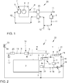
- the Fig. 1 shows a motor vehicle 20 with an internal combustion engine 2.
- the internal combustion engine 2 has an inlet side 7 and an exhaust side 8 which are connected to one another via a combustion chamber 9, the exhaust gas side 8 and the intake side 7 being additionally connected to one another via a low-pressure exhaust gas recirculation line 10, Via which an exhaust gas 11 can be conveyed from the exhaust gas side 8 back to the inlet side 7.
- the low-pressure exhaust gas recirculation line 10 is arranged in a thermally conductive connection with a first heat exchanger 5 of a cooling circuit arrangement 1 (not shown) for the dissipation of thermal energy 14 from an exhaust gas 11 routed via the low-pressure exhaust gas recirculation line 10 the at least one combustion chamber 9 of the feedable gas 12 is provided.
- the thermal energy 14 introduced into the cooling circuit arrangement 1 via the first heat exchanger 6 can be fed to the charge air cooler 6 via the cooling circuit arrangement 1.
- a turbocharger 23 (or an exhaust gas turbine) can be driven via the exhaust gas 11.
- a compressor 24 of the turbocharger 23 compresses the gas 11 that is supplied to the combustion chamber 9 of the internal combustion engine 2 via the inlet side 6.
- Fig. 2 shows a motor vehicle 20 with a first variant embodiment of a cooling circuit arrangement 1. Referring to the explanations Fig. 1 is referred.
- the cooling circuit arrangement 1 comprises at least one high-temperature circuit 3 and a low-temperature circuit 4, a first heat exchanger 5 arranged in the high-temperature circuit 3 and a charge air cooler 6 arranged in the low-temperature circuit 4.
- a component 25 is arranged in the high-temperature circuit 3 (e.g. a further heat exchanger, e.g. B. for heating an interior of the motor vehicle 20).
- the internal combustion engine 2 has an inlet side 7 and an exhaust side 8, which are connected to one another via at least one combustion chamber 9, the exhaust gas side 8 and the inlet side 7 being additionally connected to one another via a low-pressure exhaust gas recirculation line 10, via which an exhaust gas 11 from the exhaust gas side 8 can be conveyed back to the inlet side 7 if necessary.
- the first heat exchanger 5 is arranged in a thermally conductive connection with the low-pressure exhaust gas recirculation line 11.
- the charge air cooler 6 is provided for temperature control of a gas 12 that can be supplied to the at least one combustion chamber 9 via the inlet side 7.
- a second heat exchanger 13 is arranged both in the high-temperature circuit 3 and in the low-temperature circuit 4, so that heat energy 14 can be transferred between the high-temperature circuit 3 and the low-temperature circuit 4 via the second heat exchanger 13.
- the thermal energy 14 is based on the exhaust gas 11 in the low-pressure exhaust gas recirculation line 10 via the first heat exchanger 5 to the high-temperature circuit 3, from the high-temperature circuit 3 via the second heat exchanger 13 to the low-temperature circuit 4 and via the low-temperature circuit 4 to the charge air cooler 6 and via the charge air cooler 6 transferred to the gas 12.
- the cooling circuit arrangement 1 uses a common expansion tank 22 for the high-temperature circuit 3 and the low-temperature circuit 4 and a common cooling fluid 19 therefore flows through it.
- the high-temperature circuit 3 is used to cool the internal combustion engine 2, i. H. the cooling fluid 19 is used to dissipate thermal energy 14 generated in the internal combustion engine 2.
- the high-temperature circuit 3 and the low-temperature circuit 4 are fluidly separated from one another in the second heat exchanger 13 and are fluidically connected to one another here only via the common expansion tank 22.
- the high-temperature circuit 3 has a high-temperature circuit cooler 26. Via the high-temperature circuit cooler 26, the cooling fluid 19 circulating in the high-temperature circuit 3 can be cooled in the surroundings or ambient air.
- the high-temperature circuit cooler 26 is arranged in an independently operable part of the high-temperature circuit 3. The high-temperature circuit cooler 26 can thus not be acted upon until the cooling fluid 19 in the high-temperature circuit 3 has reached a minimum temperature. More thermal energy 14 can thus be transferred to the low-temperature circuit 4 via the second heat exchanger 13.
- the low-temperature circuit 4 has a low-temperature circuit cooler 15, wherein the low-temperature circuit cooler 15 can be bypassed via a bypass line 16, the bypass line 16 being pressurized until the charge air cooler 6 has reached at least a limit temperature 21 or as long as heat energy 14 is to be transferred to the charge air cooler 6 .
- the cooling fluid 19 circulating in the low-temperature circuit 4 can be cooled in the environment or ambient air via the low-temperature circuit cooler 15. This cooling can be prevented at least temporarily via the bypass line 16, the thermal energy 14 transferred from the second heat exchanger 13 to the low-temperature circuit 4 then being supplied to a greater extent to the gas 12 via the charge air cooler 6 and not discharged to the environment via the low-temperature circuit cooler 15.
- the bypass line 16 leads via the second heat exchanger 13.
- a first valve 27 can be used to regulate a volume flow in the low-temperature circuit 4 via the second heat exchanger 13 and the low-temperature circuit cooler 15.
- a first pump 17 for conveying a cooling fluid 19 through the high-temperature circuit 3 is arranged in the high-temperature circuit 3, and a second pump 18 for conveying a cooling fluid 19 through the low-temperature circuit 4 is arranged in the low-temperature circuit 4.
- a step a) of the method the internal combustion engine 2 is operated and the low-pressure exhaust gas recirculation line 10 is subjected to an exhaust gas 11.
- thermal energy 14 is diverted from the low-pressure exhaust gas recirculation line 10 via the first heat exchanger 5 into the High-temperature circuit 3.
- step c) at least part of the thermal energy 14 is transferred from the high-temperature circuit 3 via the second heat exchanger 13 to the low-temperature circuit 4.
- step d) at least part of the thermal energy 14 is transferred from the low-temperature circuit 4 to the charge air cooler 6.
- the temperature of the gas 12 to be tempered by the charge air cooler 6 takes place.
- Fig. 3 shows a motor vehicle 20 with a second embodiment variant of a cooling circuit arrangement 1. Referring to the explanations Fig. 2 is referred.
- the component 25 and the first heat exchanger 5 are arranged interchanged.
- Fig. 4 shows a motor vehicle 20 with a third variant embodiment of a cooling circuit arrangement 1. Referring to the explanations Fig. 2 is referred.
- the cooling circuit arrangement here has a separate bypass line 16 in the low-temperature circuit 4, via which the second heat exchanger 15 can be bypassed in addition to the low-temperature circuit cooler 15. This enables even more precise regulation of the temperature in the low-temperature circuit 4 and in particular on the charge air cooler 6.
- valves 27, 28 are 3/2-way valves, so they have three connections (first valve 27: connection line from the second pump 18, line to the low-temperature circuit cooler 15, line to the second valve; second valve 28: connection line from the first valve 27, separate bypass line 16 directly to the charge air cooler 6, line to the second heat exchanger 13) and two switching positions (connecting the respective connection line to one of the two lines leading away from the respective valve).
Landscapes
- Engineering & Computer Science (AREA)
- Chemical & Material Sciences (AREA)
- Combustion & Propulsion (AREA)
- Mechanical Engineering (AREA)
- General Engineering & Computer Science (AREA)
- Physics & Mathematics (AREA)
- Thermal Sciences (AREA)
- Exhaust-Gas Circulating Devices (AREA)
Abstract
Description
- Die Erfindung betrifft eine Kühlkreislaufanordnung einer Verbrennungskraftmaschine, insbesondere eines Kraftfahrzeugs.
- Eine Verbrennungskraftmaschine umfasst regelmäßig einen oder mehrere Kühlkreisläufe als Kühlkreislaufanordnung, z. B. einen Hochtemperaturkreislauf (hohe Wärmeabgabekapazität) und einen Niedertemperaturkreislauf (geringere Wärmeabgabekapazität). In jedem Kühlkreislauf ist zumindest eine Pumpe angeordnet.
- Der Hochtemperaturkreislauf ist zur Kühlung der Verbrennungskraftmaschine vorgesehen. Ein Niedertemperaturkreislauf ist z. B. zur Kühlung eines Ladeluftkühlers vorgesehen und wird im Betrieb der Verbrennungskraftmaschine regelmäßig auf einem niedrigeren Temperaturniveau betrieben als der Hochtemperaturkreislauf.
- Es sind verschiedene Strategien bekannt, durch die eine Aufheizung eines Ladeluftkühlers erreicht werden kann. Ladeluftkühler dienen der Abkühlung eines Gases, das über die Einlassseite einer Verbrennungskraftmaschine einer Brennkammer zugeführt wird. Üblicherweise werden Ladeluftkühler stromabwärts eines Verdichters angeordnet und dienen der Abführung von Wärmeenergie, die durch die Verdichtung des Gases im Verdichter eines Turboladers entsteht. Die Abkühlung des Gases bewirkt eine Erhöhung von Leistung und Wirkungsgrad der Verbrennungskraftmaschine, da durch die Verringerung der Temperatur des Gases die im gleichen Volumen enthaltene Gasmasse erhöht werden kann, so dass entsprechend mehr Kraftstoff zusammen mit dem Gas in der Brennkammer umgesetzt werden kann.
- Die Aufheizung eines Ladeluftkühlers ist insbesondere bei Rückführung eines Abgases von einer Abgasseite der Verbrennungskraftmaschine zurück zur Einlassseite über eine Niederdruck-Abgasrückführungsleitung vorteilhaft. Das Abgas enthält insbesondere einen größeren Wassergehalt als das Gas. Die Rückführung des Abgases kann z. B. zu einer Verlangsamung einer Verbrennungsrate in der Brennkammer der Verbrennungskraftmaschine führen, wobei die Einleitung von Wasser in die Brennkammer die Wahrscheinlichkeit von Fehlzündungsereignissen erhöhen kann.
- Bei Dieselmotoren kann durch eine Erwärmung des Ladeluftkühlers die Temperatur des der Brennkammer zugeführten Gases erhöht werden, so dass die Prozess- und Abgastemperatur gesteigert werden können und eine Kondensation von Wasser verhindert werden kann. Infolge der höheren Temperaturen kann eine für die Abgasnachbehandlung erforderliche Lightoff-Temperatur schneller erreicht bzw. der Wirkungsgrad der Abgasnachbehandlung verbessert werden.
- In der
DE 10 2009 051 377 A1 wird ein Antrieb für ein Hybridfahrzeug beschrieben. Der Antrieb umfasst einen Verbrennungsmotor und einen Ladeluftkühler mit einem Ladeluft-Kühlkreislauf sowie eine elektrische Antriebseinheit und einen Elektronik-Kühlkreislauf. Es wird vorgeschlagen den Ladeluft-Kühlkreislauf (also einen Niedertemperaturkreislauf) mit dem Elektronik-Kühlkreislauf über einen Wärmetauscher thermisch zu koppeln. - Aus der
DE 10 2015 111 407 A1 ist ein Kühlsystem für ein Fahrzeug bekannt, mit einem Hochtemperaturkreislauf und einem Niedertemperaturkreislauf. Diese beiden Kreisläufe sollen über eine Koppelleitung regelbar miteinander verbindbar sein. - Aus der
DE 10 2015 216 420 A1 ist eine Kühlanordnung zur Ladeluftkühlung bekannt. Über schaltbare Bypassleitungen soll eine Regelung der Ladeluftkühlung realisiert werden. - Es besteht ein ständiges Bedürfnis, vorhandene Anordnungen von Verbrennungskraftmaschinen und Kühlkreisläufen hinsichtlich des Wirkungsgrades und/oder Schadstoffemissionen zu verbessern.
- Aufgabe der vorliegenden Erfindung ist es, die mit Bezug auf den Stand der Technik angeführten Probleme zumindest teilweise zu lösen. Insbesondere soll eine Kühlkreislaufanordnung einer Verbrennungskraftmaschine zur schnelleren Erwärmung eines Ladeluftkühlers eingesetzt werden.
- Zur Lösung dieser Aufgaben trägt eine Kühlkreislaufanordnung mit den Merkmalen gemäß Patentanspruch 1 bei. Vorteilhafte Weiterbildungen sind Gegenstand der abhängigen Patentansprüche. Die in den Patentansprüchen einzeln aufgeführten Merkmale sind in technologisch sinnvoller Weise miteinander kombinierbar und können durch erläuternde Sachverhalte aus der Beschreibung und/oder Details aus den Figuren ergänzt werden, wobei weitere Ausführungsvarianten der Erfindung aufgezeigt werden.
- Es wird eine Kühlkreislaufanordnung einer Verbrennungskraftmaschine vorgeschlagen. Die Kühlkreislaufanordnung umfasst zumindest einen Hochtemperaturkreislauf und einen Niedertemperaturkreislauf, einen im Hochtemperaturkreislauf angeordneten ersten Wärmetauscher und einen im Niedertemperaturkreislauf angeordneten Ladeluftkühler. Der Hochtemperaturkreislauf ist insbesondere ausgelegt und/oder eingerichtet, das durch ihn geförderte Fluid auf eine höhere Temperatur anzuheben, als der Niedertemperaturkreislauf.
- Die Verbrennungskraftmaschine (für die die Kühlkreislaufanordnung vorgesehen und entsprechend konstruiert ist) weist eine Einlassseite und eine Abgasseite auf, die über mindestens eine Brennkammer miteinander verbunden sind, wobei die Abgasseite und die Einlassseite zusätzlich über eine Niederdruck-Abgasrückführungsleitung miteinander verbunden sind, über die ein Abgas von der Abgasseite zurück zur Einlassseite förderbar ist.
- Der erste Wärmetauscher ist in wärmeleitender Verbindung mit der Niederdruck-Abgasrückführungsleitung angeordnet. Der Ladeluftkühler ist zur Temperierung eines über die Einlassseite der mindestens einen Brennkammer zuführbaren Gases vorgesehen.
- Ein zweiter Wärmetauscher ist sowohl im Hochtemperaturkreislauf als auch im Niedertemperaturkreislauf angeordnet, so dass zwischen dem Hochtemperaturkreislauf und dem Niedertemperaturkreislauf Wärmeenergie über den zweiten Wärmetauscher übertragbar ist.
- Der zweite Wärmetauscher ist insbesondere als Gleichstrom-, Kreuzstrom-, Gegenstrom- oder Kreuzgegenstromwärmetauscher ausgeführt.
- Bei einem Gleichstromwärmetauscher werden die Kühlfluide nebeneinander in gleicher Richtung geführt. Bei einem Gegenstromwärmetauscher werden die Kühlfluide so geführt, dass sie entgegenkommend aneinander vorbeiströmen. Bei einem Kreuzstromwärmetauscher werden die Kühlfluide so geführt, dass sich ihre Richtungen kreuzen. Bei einem Kreuzgegenstromwärmetauscher werden die Kühlfluide teilweise quer zueinander und teilweise parallel gegeneinander geführt. Bei einem Kreuzgleichstromwärmetauscher werden die Kühlfluide teilweise quer zueinander und teilweise parallel in gleicher Richtung geführt.
- In Kühlkreislaufanordnungen von Verbrennungskraftmaschinen der der der Niederdruck-Abgasrückführungsleitung zugeordnete erste Wärmetauscher und der Ladeluftkühler stets in voneinander getrennten Kühlkreisläufen angeordnet sein. Dabei wäre z. B. der erste Wärmetauscher im Hochtemperaturkreislauf und der Ladeluftkühler im Niedertemperaturkreislauf angeordnet. Beide Kreisläufe würden durch eigene Pumpen betrieben, d. h. es existieren Betriebspunkte, bei denen ein als Kühlmittel bzw. als Wärmeüberträger vorgesehenes Fluid in dem (Niedertemperatur-)Kühlkreislauf ausschließlich durch die erste Pumpe und in dem (Hochtemperatur-)Kreislauf ausschließlich durch die zweite Pumpe gefördert wird bzw. förderbar ist. Eine wärmeleitende Verbindung von erstem Wärmetauscher und Ladeluftkühler wäre dabei nicht vorgesehen. Dieses Konzept wird hier nicht verfolgt.
- Hier wird nun vorgeschlagen, die vom Abgas stammende und von der Niederdruck-Abgasrückführungsleitung über den ersten Wärmetauscher in die Kühlkreislaufanordnung eingebrachte Wärmeenergie über die Kühlkreislaufanordnung dem Ladeluftkühler (regelbar) zuzuführen.
- Insbesondere wird die Wärmeenergie ausgehend vom Abgas in der Niederdruck-Abgasrückführungsleitung über den ersten Wärmetauscher auf den Hochtemperaturkreislauf, vom Hochtemperaturkreislauf über den zweiten Wärmetauscher auf den Niedertemperaturkreislauf und über den Niedertemperaturkreislauf hin zum Ladeluftkühler und über den Ladeluftkühler auf das Gas übertragen.
- Die Übertragung der Wärmeenergie erfolgt insbesondere ausschließlich über Kühlfluide, die den Hochtemperaturkreislauf und den Niedertemperaturkreislauf durchströmen.
- Insbesondere kann die Kühlkreislaufanordnung, wenn z. B. der Hochtemperaturkreislauf und der Niedertemperaturkreislauf über ein gemeinsames Reservoir befüllt und/ oder einen Ausgleichsbehälter gemeinsam nutzen, von einem gemeinsamen Kühlfluid durchströmt werden.
- Alternativ können der Hochtemperaturkreislauf und der Niedertemperaturkreislauf aber auch fluidtechnisch getrennt ausgeführt sein, wenn z. B. getrennte Reservoire und separate Ausgleichsbehälter vorgesehen sind. In diesem Fall können auch unterschiedliche oder aber gleiche Kühlfluide eingesetzt werden.
- Der Hochtemperaturkreislauf dient insbesondere der Kühlung der Verbrennungskraftmaschine, d. h. das Kühlfluid wird zur Abführung von in der Verbrennungskraftmaschine erzeugter Wärmeenergie eingesetzt.
- Der Niedertemperaturkreislauf dient insbesondere nicht der Kühlung der Verbrennungskraftmaschine, d. h., dass das hier eingesetzte Kühlfluid zur Temperierung anderer Komponenten eines Kraftfahrzeugs bzw. der Kühlkreislaufanordnung eingesetzt wird (hier zur Temperierung des Ladeluftkühlers).
- Ein in der Niederdruck-Abgasrückführungsleitung angeordneter erster Wärmetauscher kann in dem Abgas enthaltene Wärmeenergie in einen Hochtemperaturkreislauf der Kühlkreislaufanordnung überführen. Über den Hochtemperaturkreislauf kann diese Wärmeenergie zumindest teilweise oder sogar vollständig (unter Berücksichtigung des üblichen Verlustes von Wärmeenergie) über den zweiten Wärmetauscher Niedertemperaturkreislauf und darüber dem Ladeluftkühler zugeführt werden.
- Insbesondere kann so unmittelbar nach dem Kaltstart einer Verbrennungskraftmaschine Wärmeenergie des Abgases dem Ladeluftkühler zugeführt werden.
- Insbesondere ist über die von dem ersten Wärmetauscher in die Kühlkreislaufanordnung bzw. in den Hochtemperaturkreislauf eingebrachte Wärmeenergie und über den Ladeluftkühler das der mindestens einen Brennkammer zuführbare Gas regelbar bzw. kontrolliert erwärmbar.
- Insbesondere kann das der Brennkammer zugeführte Gas über den Ladeluftkühler erwärmt (Steigerung der Temperatur) werden, so dass eine Kondensation von im Gas enthaltenen Wasser verhindert oder zumindest reduziert werden kann und/oder ggf. bereits kondensiertes Wasser wieder verdampft werden kann. Bei Dieselmotoren kann durch die Erwärmung des Ladeluftkühlers die Temperatur des der Brennkammer zugeführten Gases erhöht werden, so dass die Prozess- und Abgastemperatur gesteigert werden können. Damit kann eine für die Abgasnachbehandlung erforderliche "light-off'-Temperatur schneller erreicht bzw. der Wirkungsgrad der Abgasnachbehandlung verbessert werden.
- Die Temperatur des Gases kann über eine Steuerung der an den Ladeluftkühler übertragenen Wärmeenergie geregelt bzw. eingestellt werden.
- Insbesondere sind Hochtemperaturkreislauf und der Niedertemperaturkreislauf zumindest im zweiten Wärmetauscher fluidtechnisch voneinander getrennt.
- Insbesondere weist der Hochtemperaturkreislauf einen Hochtemperaturkreislaufkühler auf. Über den Hochtemperaturkreislaufkühler kann insbesondere das in dem Hochtemperaturkreislauf zirkulierende Kühlfluid an der Umgebung bzw. Umgebungsluft abgekühlt werden. Insbesondere ist der Hochtemperaturkreislaufkühler in einem unabhängig betreibbaren Teil des Hochtemperaturkreislaufes angeordnet. Insbesondere kann der Hochtemperaturkreislaufkühler so lange nicht beaufschlagt werden, bis das Kühlfluid im Hochtemperaturkreislauf eine Mindesttemperatur erreicht hat. Damit kann mehr Wärmeenergie über den zweiten Wärmetauscher auf den Niedertemperaturkreislauf übertragen werden.
- Insbesondere weist der Niedertemperaturkreislauf einen Niedertemperaturkreislaufkühler auf, wobei der Niedertemperaturkreislaufkühler über eine Bypassleitung umgehbar ist. Über den Niedertemperaturkreislaufkühler kann insbesondere das in dem Niedertemperaturkreislauf zirkulierende Kühlfluid an der Umgebung bzw. Umgebungsluft abgekühlt werden. Über die Bypassleitung kann diese Abkühlung zumindest zeitweise unterbunden werden, wobei die von dem zweiten Wärmetauscher auf den Niedertemperaturkreislauf übertragene Wärmeenergie dann über den Ladeluftkühler in höherem Maße dem Gas zugeführt und nicht über den Niedertemperaturkreislaufkühler an die Umgebung abgeführt wird.
- Insbesondere führt die Bypassleitung über den zweiten Wärmetauscher oder zusätzlich ist der zweite Wärmetauscher über die Bypassleitung umgehbar. Wenn also eine separate Bypassleitung vorgesehen ist, über die einerseits der Niedertemperaturkreislaufkühler und andererseits auch der zweite Wärmetauscher umgangen werden kann, ist eine noch genauere Regelung der Temperatur im Niedertemperaturkreislauf und insbesondere am Ladeluftkühler möglich.
- Insbesondere sind Regeleinrichtungen (z. B. ansteuerbare Ventile) vorgesehen, über die ein Volumenstrom im Niedertemperaturkreislauf über den zweiten Wärmetauscher, den Niedertemperaturkreislaufkühler und/oder über die gesonderte Bypassleitung (also die, die nicht über den zweiten Wärmetauscher führt) regelbar ist.
- Insbesondere ist im Hochtemperaturkreislauf eine erste Pumpe zur Förderung eines Kühlfluids durch den Hochtemperaturkreislauf und im Niedertemperaturkreislauf eine zweite Pumpe zur Förderung eines Kühlfluids durch den Niedertemperaturkreislauf angeordnet, wobei zumindest die erste Pumpe oder die zweite Pumpe hinsichtlich eines Volumenstroms regelbar ist.
- Insbesondere sind beide Pumpen voneinander unabhängig regelbar.
- Insbesondere ist ein erster Volumenstrom im Hochtemperaturkreislauf über die erste Pumpe unabhängig von einem über die zweite Pumpe geregelten zweiten Volumenstrom im Niedertemperaturkreislauf regelbar und umgekehrt.
- Eine besonders vorteilhafte Ausgestaltung umfasst, dass neben dem zweiten Wärmetauscher auch zusätzlich der zweite Wärmetauscher über die separate Bypassleitung umgehbar ist. Insbesondere ist dabei mindestens ein Ventil vorgesehen, durch das ein Volumenstrom im Niedertemperaturkreislauf über den zweiten Wärmetauscher, den Niedertemperaturkreislaufkühler und über die gesonderte Bypassleitung (also die, die nicht über den zweiten Wärmetauscher führt) regelbar ist.
- Es wird weiter ein Kraftfahrzeug mit einer Verbrennungskraftmaschine vorgeschlagen, wobei die Verbrennungskraftmaschine eine Einlassseite und eine Abgasseite aufweist, die über mindestens eine Brennkammer miteinander verbunden sind, wobei die Abgasseite und die Einlassseite zusätzlich über eine Niederdruck-Abgasrückführungsleitung miteinander verbunden sind, über die ein Abgas von der Abgasseite zurück zur Einlassseite förderbar ist. Das Kraftfahrzeug weist die beschriebene Kühlkreislaufanordnung auf.
- Insbesondere weist das Kraftfahrzeug einen Turbolader mit einer Abgasturbine und einem Verdichter auf. Die Abgasturbine wird von dem Abgas beaufschlagt und angetrieben. Der Verdichter verdichtet das zur Brennkammer über die Einlassseite zugeführte Gas, ggf. inklusive des über die Niederdruck-Abgasrückführungsleitung zurückgeführten Abgases.
- Die Ausführungen zu der Kühlkreislaufanordnung gelten insbesondere gleichermaßen für das Kraftfahrzeug und umgekehrt.
- Es wird weiter ein Verfahren zum Betrieb eines Kraftfahrzeuges, insbesondere des beschriebenen Kraftfahrzeuges, vorgeschlagen, wobei das Kraftfahrzeug zumindest eine Verbrennungskraftmaschine mit einer Einlassseite und einer Abgasseite aufweist, die über mindestens eine Brennkammer miteinander verbunden sind, wobei die Abgasseite und die Einlassseite zusätzlich über eine Niederdruck-Abgasrückführungsleitung miteinander verbunden sind, über die ein Abgas von der Abgasseite zurück zur Einlassseite förderbar ist. Das Kraftfahrzeug weist die beschriebene Kühlkreislaufanordnung auf. Das Verfahren weist zumindest die folgenden Schritte auf:
- a) Betrieb der Verbrennungskraftmaschine und Beaufschlagen der Niederdruck-Abgasrückführungsleitung mit einem Abgas;
- b) Ableiten von Wärmeenergie aus der Niederdruck-Abgasrückführungsleitung über den ersten Wärmetauscher in den Hochtemperaturkreislauf;
- c) Übertragen zumindest eines Teils der Wärmeenergie aus dem Hochtemperaturkreislauf über den zweiten Wärmetauscher auf den Niedertemperaturkreislauf;
- d) Übertragen zumindest eines Teils der Wärmeenergie aus dem Niedertemperaturkreislauf auf den Ladeluftkühler.
- Im Rahmen des Schrittes d) erfolgt insbesondere eine Temperierung des durch den Ladeluftkühler zu temperierenden Gases.
- Insbesondere wird das Verfahren zum Aufheizen des Ladeluftkühlers und damit zur Erwärmung des über die Einlassseite der mindestens einen Brennkammer zuführbaren Gases durchgeführt.
- Insbesondere weist der Niedertemperaturkreislauf einen Niedertemperaturkreislaufkühler auf, der über eine Bypassleitung umgehbar ist; wobei die Bypassleitung beaufschlagt wird, bis der Ladeluftkühler mindestens eine Grenztemperatur erreicht hat oder solange, wie Wärmeenergie hin zum Ladeluftkühler übertragen werden soll.
- Insbesondere weist der Hochtemperaturkreislauf einen Hochtemperaturkreislaufkühler auf. Insbesondere wird der Hochtemperaturkreislaufkühler so lange nicht über den Hochtemperaturkreislauf und das darin zirkulierende Kühlfluid beaufschlagt, bis das Kühlfluid im Hochtemperaturkreislauf eine Mindesttemperatur (oder der Ladeluftkühler eine Grenztemperatur) erreicht hat.
- Sobald z. B. die Grenztemperatur erreicht ist bzw. Wärmeenergie nicht mehr in dem bisherigen Maße übertragen werden soll, kann die Kühlkreislaufanordnung den Niedertemperaturkreislaufkühler und/oder den Hochtemperaturkreislaufkühler einbeziehen, so dass das in der Kühlkreislaufanordnung zirkulierende Kühlfluid zumindest über einen der Kreislaufkühler abgekühlt werden kann.
- Die Ausführungen zu dem Verfahren gelten gleichermaßen für die Kühlkreislaufanordnung und das Kraftfahrzeug und umgekehrt.
- Vorsorglich sei angemerkt, dass die hier verwendeten Zahlwörter ("erste", "zweite", ...) vorrangig (nur) zur Unterscheidung von mehreren gleichartigen Gegenständen, Größen oder Prozessen dienen, also insbesondere keine Abhängigkeit und/oder Reihenfolge dieser Gegenstände, Größen oder Prozesse zueinander zwingend vorgeben. Sollte eine Abhängigkeit und/oder Reihenfolge erforderlich sein, ist dies hier explizit angegeben oder es ergibt sich offensichtlich für den Fachmann beim Studium der konkret beschriebenen Ausgestaltung.
- Die Erfindung sowie das technische Umfeld werden nachfolgend anhand der beiliegenden Figuren näher erläutert. Es ist darauf hinzuweisen, dass die Erfindung durch die angeführten Ausführungsbeispiele nicht beschränkt werden soll. Insbesondere ist es, soweit nicht explizit anders dargestellt, auch möglich, Teilaspekte der in den Figuren erläuterten Sachverhalte zu extrahieren und mit anderen Bestandteilen und Erkenntnissen aus der vorliegenden Beschreibung zu kombinieren. Insbesondere ist darauf hinzuweisen, dass die Figuren und insbesondere die dargestellten Größenverhältnisse nur schematisch sind. Es zeigen:
- Fig. 1:
- ein Kraftfahrzeug;
- Fig. 2:
- ein Kraftfahrzeug mit einer ersten Ausführungsvariante einer Kühlkreislaufanordnung;
- Fig. 3:
- ein Kraftfahrzeug mit einer zweiten Ausführungsvariante einer Kühlkreislaufanordnung; und
- Fig. 4:
- ein Kraftfahrzeug mit einer dritten Ausführungsvariante einer Kühlkreislaufanordnung.
- Die
Fig. 1 zeigt ein Kraftfahrzeug 20 mit einer Verbrennungskraftmaschine 2. Die Verbrennungskraftmaschine 2 weist eine Einlassseite 7 und eine Abgasseite 8 auf, die über eine Brennkammer 9 miteinander verbunden sind, wobei die Abgasseite 8 und die Einlassseite 7 zusätzlich über eine Niederdruck-Abgasrückführungsleitung 10 miteinander verbunden sind, über die ein Abgas 11 von der Abgasseite 8 zurück zur Einlassseite 7 förderbar ist. Die Niederdruck-Abgasrückführungsleitung 10 ist in wärmeleitender Verbindung mit einem ersten Wärmetauscher 5 einer Kühlkreislaufanordnung 1 (nicht dargestellt) angeordnet zur Ableitung von Wärmeenergie 14 aus einem über die Niederdruck-Abgasrückführungsleitung 10 geführten Abgas 11. Ein Ladeluftkühler 6 ist zur Temperierung eines über die Einlassseite 7 der mindestens einen Brennkammer 9 zuführbaren Gases 12 vorgesehen. Die über den ersten Wärmetauscher 6 in die Kühlkreislaufanordnung 1 eingebrachte Wärmeenergie 14 ist über die Kühlkreislaufanordnung 1 dem Ladeluftkühler 6 zuführbar. Ein Turbolader 23 (bzw. eine Abgasturbine) ist über das Abgas 11 antreibbar. Ein Verdichter 24 des Turboladers 23 verdichtet das Gas 11, das der Brennkammer 9 der Verbrennungskraftmaschine 2 über die Einlassseite 6 zugeführt wird. -
Fig. 2 zeigt ein Kraftfahrzeug 20 mit einer ersten Ausführungsvariante einer Kühlkreislaufanordnung 1. Auf die Ausführungen zuFig. 1 wird verwiesen. - Die Kühlkreislaufanordnung 1 umfasst zumindest einen Hochtemperaturkreislauf 3 und einen Niedertemperaturkreislauf 4, einen im Hochtemperaturkreislauf 3 angeordneten ersten Wärmetauscher 5 und einen im Niedertemperaturkreislauf 4 angeordneten Ladeluftkühler 6. Im Hochtemperaturkreislauf 3 ist zudem eine Komponente 25 angeordnet (z. B. ein weiterer Wärmetauscher, z. B. zum Beheizen eines Innenraums des Kraftfahrzeuges 20).
- Die Verbrennungskraftmaschine 2 weist eine Einlassseite 7 und eine Abgasseite 8 auf, die über mindestens eine Brennkammer 9 miteinander verbunden sind, wobei die Abgasseite 8 und die Einlassseite 7 zusätzlich über eine Niederdruck-Abgasrückführungsleitung 10 miteinander verbunden sind, über die ein Abgas 11 von der Abgasseite 8 zurück zur Einlassseite 7 bedarfsweise förderbar ist.
- Der erste Wärmetauscher 5 ist in wärmeleitender Verbindung mit der Niederdruck-Abgasrückführungsleitung 11 angeordnet. Der Ladeluftkühler 6 ist zur Temperierung eines über die Einlassseite 7 der mindestens einen Brennkammer 9 zuführbaren Gases 12 vorgesehen.
- Ein zweiter Wärmetauscher 13 ist sowohl im Hochtemperaturkreislauf 3 als auch im Niedertemperaturkreislauf 4 angeordnet, so dass zwischen dem Hochtemperaturkreislauf 3 und dem Niedertemperaturkreislauf 4 Wärmeenergie 14 über den zweiten Wärmetauscher 13 übertragbar ist.
- Die Wärmeenergie 14 wird ausgehend vom Abgas 11 in der Niederdruck-Abgasrückführungsleitung 10 über den ersten Wärmetauscher 5 auf den Hochtemperaturkreislauf 3, vom Hochtemperaturkreislauf 3 über den zweiten Wärmetauscher 13 auf den Niedertemperaturkreislauf 4 und über den Niedertemperaturkreislauf 4 hin zum Ladeluftkühler 6 und über den Ladeluftkühler 6 auf das Gas 12 übertragen.
- Die Kühlkreislaufanordnung 1 nutzt für den Hochtemperaturkreislauf 3 und den Niedertemperaturkreislauf 4 einen Ausgleichsbehälter 22 gemeinsam und wird daher von einem gemeinsamen Kühlfluid 19 durchströmt.
- Der Hochtemperaturkreislauf 3 dient der Kühlung der Verbrennungskraftmaschine 2, d. h. das Kühlfluid 19 wird zur Abführung von in der Verbrennungskraftmaschine 2 erzeugter Wärmeenergie 14 eingesetzt.
- Hochtemperaturkreislauf 3 und Niedertemperaturkreislauf 4 sind im zweiten Wärmetauscher 13 fluidtechnisch voneinander getrennt und hier nur über den gemeinsamen Ausgleichsbehälter 22 fluidtechnisch miteinander verbunden.
- Der Hochtemperaturkreislauf 3 weist einen Hochtemperaturkreislaufkühler 26 auf. Über den Hochtemperaturkreislaufkühler 26 kann das in dem Hochtemperaturkreislauf 3 zirkulierende Kühlfluid 19 an der Umgebung bzw. Umgebungsluft abgekühlt werden. Der Hochtemperaturkreislaufkühler 26 ist in einem unabhängig betreibbaren Teil des Hochtemperaturkreislaufes 3 angeordnet. Damit kann der Hochtemperaturkreislaufkühler 26 so lange nicht beaufschlagt werden, bis das Kühlfluid 19 im Hochtemperaturkreislauf 3 eine Mindesttemperatur erreicht hat. Damit kann mehr Wärmeenergie 14 über den zweiten Wärmetauscher 13 auf den Niedertemperaturkreislauf 4 übertragen werden.
- Der Niedertemperaturkreislauf 4 weist einen Niedertemperaturkreislaufkühler 15 auf, wobei der Niedertemperaturkreislaufkühler 15 über eine Bypassleitung 16 umgehbar ist, wobei die Bypassleitung 16 beaufschlagt wird, bis der Ladeluftkühler 6 mindestens eine Grenztemperatur 21 erreicht hat oder solange, wie Wärmeenergie 14 hin zum Ladeluftkühler 6 übertragen werden soll. Über den Niedertemperaturkreislaufkühler 15 kann das in dem Niedertemperaturkreislauf 4 zirkulierende Kühlfluid 19 an der Umgebung bzw. Umgebungsluft abgekühlt werden. Über die Bypassleitung 16 kann diese Abkühlung zumindest zeitweise unterbunden werden, wobei die von dem zweiten Wärmetauscher 13 auf den Niedertemperaturkreislauf 4 übertragene Wärmeenergie 14 dann über den Ladeluftkühler 6 in höherem Maße dem Gas 12 zugeführt und nicht über den Niedertemperaturkreislaufkühler 15 an die Umgebung abgeführt wird.
- Die Bypassleitung 16 führt über den zweiten Wärmetauscher 13. Über ein erstes Ventil 27 ist ein Volumenstrom im Niedertemperaturkreislauf 4 über den zweiten Wärmetauscher 13 und den Niedertemperaturkreislaufkühler 15 regelbar.
- Im Hochtemperaturkreislauf 3 ist eine erste Pumpe 17 zur Förderung eines Kühlfluids 19 durch den Hochtemperaturkreislauf 3 und im Niedertemperaturkreislauf 4 eine zweite Pumpe 18 zur Förderung eines Kühlfluids 19 durch den Niedertemperaturkreislauf 4 angeordnet.
- In einem Schritt a) des Verfahrens erfolgt ein Betrieb der Verbrennungskraftmaschine 2 und ein Beaufschlagen der Niederdruck-Abgasrückführungsleitung 10 mit einem Abgas 11. In einem Schritt b) erfolgt ein Ableiten von Wärmeenergie 14 aus der Niederdruck-Abgasrückführungsleitung 10 über den ersten Wärmetauscher 5 in den Hochtemperaturkreislauf 3. In Schritt c) erfolgt ein Übertragen zumindest eines Teils der Wärmeenergie 14 aus dem Hochtemperaturkreislauf 3 über den zweiten Wärmetauscher 13 auf den Niedertemperaturkreislauf 4. In Schritt d) erfolgt ein Übertragen zumindest eines Teils der Wärmeenergie 14 aus dem Niedertemperaturkreislauf 4 auf den Ladeluftkühler 6. Im Rahmen des Schrittes d) erfolgt eine Temperierung des durch den Ladeluftkühler 6 zu temperierenden Gases 12.
-
Fig. 3 zeigt ein Kraftfahrzeug 20 mit einer zweiten Ausführungsvariante einer Kühlkreislaufanordnung 1. Auf die Ausführungen zuFig. 2 wird verwiesen. - Im Unterschied zur ersten Ausführungsvariante sind hier die Komponente 25 und der erste Wärmetauscher 5 miteinander vertauscht angeordnet.
-
Fig. 4 zeigt ein Kraftfahrzeug 20 mit einer dritten Ausführungsvariante einer Kühlkreislaufanordnung 1. Auf die Ausführungen zuFig. 2 wird verwiesen. - Im Unterschied zur ersten Ausführungsvariante weist die Kühlkreislaufanordnung hier im Niedertemperaturkreislauf 4 eine separate Bypassleitung 16 auf, über die neben dem Niedertemperaturkreislaufkühler 15 auch der zweite Wärmetauscher 15 umgangen werden kann. Damit ist eine noch genauere Regelung der Temperatur im Niedertemperaturkreislauf 4 und insbesondere am Ladeluftkühler 6 möglich.
- Hier ist zusätzlich zu dem ersten Ventil 27 ein zweites Ventil 28 vorgesehen. Beide Ventile 27, 28 sind 3/2-Wege-Ventile, weisen also drei Anschlüsse (erstes Ventil 27: Anschlussleitung von der zweiten Pumpe 18, Leitung hin zum Niedertemperaturkreislaufkühler 15, Leitung hin zum zweiten Ventil; zweites Ventil 28: Anschlussleitung vom ersten Ventil 27, separate Bypassleitung 16 direkt hin zum Ladeluftkühler 6, Leitung hin zum zweiten Wärmetauscher 13) und zwei Schaltstellungen (Verbinden der jeweiligen Anschlussleitung mit einer der beiden vom jeweiligen Ventil wegführenden Leitungen) auf.
-
- 1
- Kühlkreislaufanordnung
- 2
- Verbrennungsmotor
- 3
- Hochtemperaturkreislauf
- 4
- Niedertemperaturkreislauf
- 5
- erster Wärmetauscher
- 6
- Ladeluftkühler
- 7
- Einlassseite
- 8
- Abgasseite
- 9
- Brennkammer
- 10
- Niederdruck-Abgasrückführungsleitung
- 11
- Abgas
- 12
- Gas
- 13
- zweiter Wärmetauscher
- 14
- Wärmeenergie
- 15
- Niedertemperaturkreislaufkühler
- 16
- Bypassleitung
- 17
- erste Pumpe
- 18
- zweite Pumpe
- 19
- Kühlfluid
- 20
- Kraftfahrzeug
- 21
- Grenztemperatur
- 22
- Ausgleichbehälter
- 23
- Turbolader
- 24
- Verdichter
- 25
- Komponente
- 26
- Hochtemperaturkreislaufkühler
- 27
- erstes Ventil
- 28
- zweites Ventil
Claims (10)
- Kühlkreislaufanordnung (1) einer Verbrennungskraftmaschine (2), zumindest umfassend einen Hochtemperaturkreislauf (3) und einen Niedertemperaturkreislauf (4), einen im Hochtemperaturkreislauf (3) angeordneten ersten Wärmetauscher (5) und einen im Niedertemperaturkreislauf angeordneten Ladeluftkühler (6); wobei die Verbrennungskraftmaschine (2) eine Einlassseite (7) und eine Abgasseite (8) aufweist, die über mindestens eine Brennkammer (9) miteinander verbunden sind, wobei die Abgasseite (8) und die Einlassseite (7) zusätzlich über eine Niederdruck-Abgasrückführungsleitung (10) miteinander verbunden sind, über die ein Abgas (11) von der Abgasseite (8) zurück zur Einlassseite (7) förderbar ist; wobei der erste Wärmetauscher (5) in wärmeleitender Verbindung mit der Niederdruck-Abgasrückführungsleitung (10) angeordnet ist, wobei der Ladeluftkühler (6) zur Temperierung eines über die Einlassseite (7) der mindestens einen Brennkammer (9) zuführbaren Gases (12) vorgesehen ist; wobei ein zweiter Wärmetauscher (13) sowohl im Hochtemperaturkreislauf (3) als auch im Niedertemperaturkreislauf (4) angeordnet ist, so dass zwischen dem Hochtemperaturkreislauf (3) und dem Niedertemperaturkreislauf (4) Wärmeenergie (14) über den zweiten Wärmetauscher (13) übertragbar ist.
- Kühlkreislaufanordnung (1) nach Patentanspruch 1, wobei über die von dem ersten Wärmetauscher (5) in die Kühlkreislaufanordnung (1) eingebrachte Wärmeenergie (14) und über den Ladeluftkühler (6) das der mindestens einen Brennkammer (9) zuführbare Gas (12) regelbar erwärmbar ist.
- Kühlkreislaufanordnung (1) nach einem der vorhergehenden Patentansprüche, wobei der Hochtemperaturkreislauf (3) und der Niedertemperaturkreislauf (4) zumindest im zweiten Wärmetauscher (13) fluidtechnisch getrennt sind.
- Kühlkreislaufanordnung (1) nach einem der vorhergehenden Patentansprüche, wobei der Niedertemperaturkreislauf (4) einen Niedertemperaturkreislaufkühler (15) aufweist, wobei der Niedertemperaturkreislaufkühler (15) über eine Bypassleitung (16) umgehbar ist.
- Kühlkreislaufanordnung (1) nach Patentanspruch 4, wobei die Bypassleitung (16) über den zweiten Wärmetauscher (13) führt oder zusätzlich der zweite Wärmetauscher (13) über die Bypassleitung (16) umgehbar ist.
- Kühlkreislaufanordnung (1) nach einem der vorhergehenden Patentansprüche, wobei im Hochtemperaturkreislauf (3) eine erste Pumpe (17) zur Förderung eines Kühlfluids (18) durch den Hochtemperaturkreislauf (3) und im Niedertemperaturkreislauf (4) eine zweite Pumpe (19) zur Förderung eines Kühlfluids (18) durch den Niedertemperaturkreislauf (4) angeordnet ist, wobei zumindest die erste Pumpe (17) oder die zweite Pumpe (19) hinsichtlich eines Volumenstroms regelbar ist.
- Kraftfahrzeug (20) mit einer Verbrennungskraftmaschine (2), wobei die Verbrennungskraftmaschine (2) eine Einlassseite (7) und eine Abgasseite (8) aufweist, die über mindestens eine Brennkammer (9) miteinander verbunden sind, wobei die Abgasseite (8) und die Einlassseite (7) zusätzlich über eine Niederdruck-Abgasrückführungsleitung (10) miteinander verbunden sind, über die ein Abgas (11) von der Abgasseite (8) zurück zur Einlassseite (7) förderbar ist; wobei das Kraftfahrzeug (10) eine Kühlkreislaufanordnung (1) nach einem der vorhergehenden Patentansprüche aufweist.
- Verfahren zum Betrieb eines Kraftfahrzeuges (20), wobei das Kraftfahrzeug (20) zumindest eine Verbrennungskraftmaschine (2) mit einer Einlassseite (7) und einer Abgasseite (8) aufweist, die über mindestens eine Brennkammer (9) miteinander verbunden sind, wobei die Abgasseite (8) und die Einlassseite (7) zusätzlich über eine Niederdruck-Abgasrückführungsleitung (10) miteinander verbunden sind, über die ein Abgas (11) von der Abgasseite (8) zurück zur Einlassseite (7) förderbar ist, wobei das Kraftfahrzeug (20) eine Kühlkreislaufanordnung (1) nach einem der vorhergehenden Patentansprüche aufweist; wobei das Verfahren zumindest die folgenden Schritte aufweist:a) Betrieb der Verbrennungskraftmaschine (2) und Beaufschlagen der Niederdruck-Abgasrückführungsleitung (10) mit einem Abgas (11);b) Ableiten von Wärmeenergie (14) aus der Niederdruck-Abgasrückführungsleitung (10) über den ersten Wärmetauscher (5) in den Hochtemperaturkreislauf (3);c) Übertragen zumindest eines Teils der Wärmeenergie (14) aus dem Hochtemperaturkreislauf (3) über den zweiten Wärmetauscher (13) auf den Niedertemperaturkreislauf (4);d) Übertragen zumindest eines Teils der Wärmeenergie (14) aus dem Niedertemperaturkreislauf (4) auf den Ladeluftkühler (6).
- Verfahren nach Patentanspruch 8, wobei das Verfahren zum Aufheizen des Ladeluftkühlers (6) und damit zur Erwärmung des über die Einlassseite (7) der mindestens einen Brennkammer (9) zuführbaren Gases (12) durchgeführt wird.
- Verfahren nach einem der vorhergehenden Patentansprüche 8 und 9, wobei der Niedertemperaturkreislauf (4) einen Niedertemperaturkreislaufkühler (15) aufweist, der über eine Bypassleitung (16) umgehbar ist; wobei die Bypassleitung (16) beaufschlagt wird, bis der Ladeluftkühler (6) mindestens eine Grenztemperatur (21) erreicht hat.
Applications Claiming Priority (1)
| Application Number | Priority Date | Filing Date | Title |
|---|---|---|---|
| DE102019207000.0A DE102019207000A1 (de) | 2019-05-14 | 2019-05-14 | Kühlkreislaufanordnung einer Verbrennungskraftmaschine |
Publications (2)
| Publication Number | Publication Date |
|---|---|
| EP3739180A1 true EP3739180A1 (de) | 2020-11-18 |
| EP3739180B1 EP3739180B1 (de) | 2023-06-07 |
Family
ID=70285505
Family Applications (1)
| Application Number | Title | Priority Date | Filing Date |
|---|---|---|---|
| EP20169039.3A Active EP3739180B1 (de) | 2019-05-14 | 2020-04-09 | Kühlkreislaufanordnung einer verbrennungskraftmaschine |
Country Status (2)
| Country | Link |
|---|---|
| EP (1) | EP3739180B1 (de) |
| DE (1) | DE102019207000A1 (de) |
Cited By (1)
| Publication number | Priority date | Publication date | Assignee | Title |
|---|---|---|---|---|
| CN120193925A (zh) * | 2024-04-23 | 2025-06-24 | 上海理想汽车科技有限公司 | 一种低温冷却循环系统、方法以及车辆 |
Families Citing this family (2)
| Publication number | Priority date | Publication date | Assignee | Title |
|---|---|---|---|---|
| DE102020201350B4 (de) * | 2020-02-04 | 2025-10-09 | Volkswagen Aktiengesellschaft | Baugruppe für ein Kühlsystem eines Kraftfahrzeugs mit einem Wärmetauscher, einem Steuerventil und einer Stellvorrichtung |
| DE102020115018A1 (de) | 2020-06-05 | 2021-12-09 | Volkswagen Aktiengesellschaft | Kühlkreislaufanordnung einer Verbrennungskraftmaschine |
Citations (6)
| Publication number | Priority date | Publication date | Assignee | Title |
|---|---|---|---|---|
| DE102006008826A1 (de) * | 2006-02-25 | 2007-08-30 | Audi Ag | Thermische Entdrosselung bei aufgeladenen Verbrennungsmotoren |
| DE102009051377A1 (de) | 2009-10-30 | 2011-05-05 | Bayerische Motoren Werke Aktiengesellschaft | Antrieb für ein Hybridfahrzeug |
| DE102015216420A1 (de) | 2014-08-29 | 2016-03-03 | Volkswagen Aktiengesellschaft | Kühlanordnung zur Ladeluftkühlung |
| EP3023609A1 (de) * | 2014-11-20 | 2016-05-25 | MAN Truck & Bus AG | Kühlsystem für ein fahrzeug, insbesondere für ein nutzfahrzeug |
| DE102015111407A1 (de) | 2015-07-14 | 2017-01-19 | Dr. Ing. H.C. F. Porsche Aktiengesellschaft | Kühlsystem für ein Fahrzeug |
| DE102017123469A1 (de) * | 2017-10-10 | 2019-04-11 | Volkswagen Aktiengesellschaft | Verfahren zum Betreiben einer Brennkraftmaschine, Brennkraftmaschine und Kraftfahrzeug |
Family Cites Families (1)
| Publication number | Priority date | Publication date | Assignee | Title |
|---|---|---|---|---|
| DE202013100932U1 (de) * | 2013-03-04 | 2013-03-19 | Ford Global Technologies, Llc. | Ladeluftkühlersystem mit integrierter Aufheizeinrichtung |
-
2019
- 2019-05-14 DE DE102019207000.0A patent/DE102019207000A1/de not_active Withdrawn
-
2020
- 2020-04-09 EP EP20169039.3A patent/EP3739180B1/de active Active
Patent Citations (6)
| Publication number | Priority date | Publication date | Assignee | Title |
|---|---|---|---|---|
| DE102006008826A1 (de) * | 2006-02-25 | 2007-08-30 | Audi Ag | Thermische Entdrosselung bei aufgeladenen Verbrennungsmotoren |
| DE102009051377A1 (de) | 2009-10-30 | 2011-05-05 | Bayerische Motoren Werke Aktiengesellschaft | Antrieb für ein Hybridfahrzeug |
| DE102015216420A1 (de) | 2014-08-29 | 2016-03-03 | Volkswagen Aktiengesellschaft | Kühlanordnung zur Ladeluftkühlung |
| EP3023609A1 (de) * | 2014-11-20 | 2016-05-25 | MAN Truck & Bus AG | Kühlsystem für ein fahrzeug, insbesondere für ein nutzfahrzeug |
| DE102015111407A1 (de) | 2015-07-14 | 2017-01-19 | Dr. Ing. H.C. F. Porsche Aktiengesellschaft | Kühlsystem für ein Fahrzeug |
| DE102017123469A1 (de) * | 2017-10-10 | 2019-04-11 | Volkswagen Aktiengesellschaft | Verfahren zum Betreiben einer Brennkraftmaschine, Brennkraftmaschine und Kraftfahrzeug |
Cited By (2)
| Publication number | Priority date | Publication date | Assignee | Title |
|---|---|---|---|---|
| CN120193925A (zh) * | 2024-04-23 | 2025-06-24 | 上海理想汽车科技有限公司 | 一种低温冷却循环系统、方法以及车辆 |
| WO2025223301A1 (zh) * | 2024-04-23 | 2025-10-30 | 上海理想汽车科技有限公司 | 一种低温冷却循环系统、方法以及车辆 |
Also Published As
| Publication number | Publication date |
|---|---|
| EP3739180B1 (de) | 2023-06-07 |
| DE102019207000A1 (de) | 2020-11-19 |
Similar Documents
| Publication | Publication Date | Title |
|---|---|---|
| DE102010010594B4 (de) | Kühlkreislauf für eine Brennkraftmaschine | |
| DE102012200562A1 (de) | Motorsystem | |
| DE102006024315A1 (de) | Fahrzeugkühlsystem | |
| EP2846017B1 (de) | Wärmetauschvorrichtung und Antriebseinheit für ein Kraftfahrzeug | |
| WO2004090303A1 (de) | Kreislaufanordnung zur kühlung von ladeluft und verfahren zum betreiben einer derartigen kreislaufanordnung | |
| EP3739180B1 (de) | Kühlkreislaufanordnung einer verbrennungskraftmaschine | |
| DE102006019282A1 (de) | Abgasrückführsystem für eine Brennkraftmaschine | |
| DE102009028925A1 (de) | Antriebsvorrichtung | |
| DE102013021259A1 (de) | Aufladeeinrichtung für eine Verbrennungskraftmaschine eines Kraftwagens sowie Verfahren zum Betreiben einer solchen Aufladeeinrichtung | |
| EP2808527B1 (de) | Verfahren und vorrichtung zum betreiben einer brennkraftmaschine | |
| EP2212540B1 (de) | Vorrichtung und verfahren zur rückführung von abgas eines verbrennungsmotors | |
| DE102009017719B4 (de) | Vorrichtung und Verfahren zur Regelung der Temperatur der Ladeluft | |
| EP3023622B1 (de) | Kühlsystem für ein fahrzeug, insbesondere für ein nutzfahrzeug | |
| DE102019205414A1 (de) | Kühlkreislaufanordnung einer Verbrennungskraftmaschine | |
| DE102018101999A1 (de) | Kühlkreislaufanordnung einer Verbrennungskraftmaschine und Verfahren zum Betrieb eines Kraftfahrzeuges | |
| DE102008031122B4 (de) | Anordnung zum Aufheizen eines Kraftfahrzeuggetriebes | |
| EP1727976B1 (de) | Brennkraftmaschine mit befeuchtungseinrichtung und wärmetauscher | |
| DE102017011851A1 (de) | Anordnung zur Umwandlung thermischer Energie aus Verlustwärme einer Verbrennungskraftmaschine | |
| EP3919726B1 (de) | Kühlkreislaufanordnung einer verbrennungskraftmaschine | |
| EP3832082A1 (de) | Kühlkreislaufanordnung eines kraftfahrzeugs | |
| DE102019206450A1 (de) | Motorsystem | |
| EP3754166B1 (de) | Brennkraftmaschine mit einem einen agr-kühler umfassenden kühlsystem | |
| DE102013011563A1 (de) | Kühlkreislauf einer Brennkraftmaschine sowie Verfahren zum Betreiben eines Kühlkreislaufs | |
| EP2930321B1 (de) | Antriebsvorrichtung eines Kraftfahrzeugs mit einem Gasturbinensystem zur Energierückgewinnung und Verfahren zum Betrieb der Antriebsvorrichtung | |
| DE102024126546A1 (de) | Ansaugluftkompressor und Ladeluftkühler als Wärmequellen in Hybridfahrzeugen |
Legal Events
| Date | Code | Title | Description |
|---|---|---|---|
| PUAI | Public reference made under article 153(3) epc to a published international application that has entered the european phase |
Free format text: ORIGINAL CODE: 0009012 |
|
| STAA | Information on the status of an ep patent application or granted ep patent |
Free format text: STATUS: THE APPLICATION HAS BEEN PUBLISHED |
|
| AK | Designated contracting states |
Kind code of ref document: A1 Designated state(s): AL AT BE BG CH CY CZ DE DK EE ES FI FR GB GR HR HU IE IS IT LI LT LU LV MC MK MT NL NO PL PT RO RS SE SI SK SM TR |
|
| AX | Request for extension of the european patent |
Extension state: BA ME |
|
| STAA | Information on the status of an ep patent application or granted ep patent |
Free format text: STATUS: REQUEST FOR EXAMINATION WAS MADE |
|
| 17P | Request for examination filed |
Effective date: 20210518 |
|
| RBV | Designated contracting states (corrected) |
Designated state(s): AL AT BE BG CH CY CZ DE DK EE ES FI FR GB GR HR HU IE IS IT LI LT LU LV MC MK MT NL NO PL PT RO RS SE SI SK SM TR |
|
| REG | Reference to a national code |
Ref country code: DE Ref legal event code: R079 Ref document number: 502020003478 Country of ref document: DE Free format text: PREVIOUS MAIN CLASS: F02B0029040000 Ipc: F01P0007160000 |
|
| RIC1 | Information provided on ipc code assigned before grant |
Ipc: F02B 29/04 20060101ALI20221124BHEP Ipc: F02M 26/28 20160101ALI20221124BHEP Ipc: F02M 26/06 20160101ALI20221124BHEP Ipc: F01P 3/20 20060101ALI20221124BHEP Ipc: F01P 3/12 20060101ALI20221124BHEP Ipc: F01P 7/16 20060101AFI20221124BHEP |
|
| GRAP | Despatch of communication of intention to grant a patent |
Free format text: ORIGINAL CODE: EPIDOSNIGR1 |
|
| STAA | Information on the status of an ep patent application or granted ep patent |
Free format text: STATUS: GRANT OF PATENT IS INTENDED |
|
| INTG | Intention to grant announced |
Effective date: 20230102 |
|
| GRAS | Grant fee paid |
Free format text: ORIGINAL CODE: EPIDOSNIGR3 |
|
| GRAA | (expected) grant |
Free format text: ORIGINAL CODE: 0009210 |
|
| STAA | Information on the status of an ep patent application or granted ep patent |
Free format text: STATUS: THE PATENT HAS BEEN GRANTED |
|
| AK | Designated contracting states |
Kind code of ref document: B1 Designated state(s): AL AT BE BG CH CY CZ DE DK EE ES FI FR GB GR HR HU IE IS IT LI LT LU LV MC MK MT NL NO PL PT RO RS SE SI SK SM TR |
|
| REG | Reference to a national code |
Ref country code: GB Ref legal event code: FG4D Free format text: NOT ENGLISH |
|
| REG | Reference to a national code |
Ref country code: CH Ref legal event code: EP Ref country code: AT Ref legal event code: REF Ref document number: 1575731 Country of ref document: AT Kind code of ref document: T Effective date: 20230615 |
|
| REG | Reference to a national code |
Ref country code: DE Ref legal event code: R096 Ref document number: 502020003478 Country of ref document: DE |
|
| REG | Reference to a national code |
Ref country code: LT Ref legal event code: MG9D |
|
| REG | Reference to a national code |
Ref country code: NL Ref legal event code: MP Effective date: 20230607 |
|
| PG25 | Lapsed in a contracting state [announced via postgrant information from national office to epo] |
Ref country code: SE Free format text: LAPSE BECAUSE OF FAILURE TO SUBMIT A TRANSLATION OF THE DESCRIPTION OR TO PAY THE FEE WITHIN THE PRESCRIBED TIME-LIMIT Effective date: 20230607 Ref country code: NO Free format text: LAPSE BECAUSE OF FAILURE TO SUBMIT A TRANSLATION OF THE DESCRIPTION OR TO PAY THE FEE WITHIN THE PRESCRIBED TIME-LIMIT Effective date: 20230907 Ref country code: ES Free format text: LAPSE BECAUSE OF FAILURE TO SUBMIT A TRANSLATION OF THE DESCRIPTION OR TO PAY THE FEE WITHIN THE PRESCRIBED TIME-LIMIT Effective date: 20230607 |
|
| PG25 | Lapsed in a contracting state [announced via postgrant information from national office to epo] |
Ref country code: RS Free format text: LAPSE BECAUSE OF FAILURE TO SUBMIT A TRANSLATION OF THE DESCRIPTION OR TO PAY THE FEE WITHIN THE PRESCRIBED TIME-LIMIT Effective date: 20230607 Ref country code: NL Free format text: LAPSE BECAUSE OF FAILURE TO SUBMIT A TRANSLATION OF THE DESCRIPTION OR TO PAY THE FEE WITHIN THE PRESCRIBED TIME-LIMIT Effective date: 20230607 Ref country code: LV Free format text: LAPSE BECAUSE OF FAILURE TO SUBMIT A TRANSLATION OF THE DESCRIPTION OR TO PAY THE FEE WITHIN THE PRESCRIBED TIME-LIMIT Effective date: 20230607 Ref country code: LT Free format text: LAPSE BECAUSE OF FAILURE TO SUBMIT A TRANSLATION OF THE DESCRIPTION OR TO PAY THE FEE WITHIN THE PRESCRIBED TIME-LIMIT Effective date: 20230607 Ref country code: HR Free format text: LAPSE BECAUSE OF FAILURE TO SUBMIT A TRANSLATION OF THE DESCRIPTION OR TO PAY THE FEE WITHIN THE PRESCRIBED TIME-LIMIT Effective date: 20230607 Ref country code: GR Free format text: LAPSE BECAUSE OF FAILURE TO SUBMIT A TRANSLATION OF THE DESCRIPTION OR TO PAY THE FEE WITHIN THE PRESCRIBED TIME-LIMIT Effective date: 20230908 |
|
| PG25 | Lapsed in a contracting state [announced via postgrant information from national office to epo] |
Ref country code: FI Free format text: LAPSE BECAUSE OF FAILURE TO SUBMIT A TRANSLATION OF THE DESCRIPTION OR TO PAY THE FEE WITHIN THE PRESCRIBED TIME-LIMIT Effective date: 20230607 |
|
| PG25 | Lapsed in a contracting state [announced via postgrant information from national office to epo] |
Ref country code: SK Free format text: LAPSE BECAUSE OF FAILURE TO SUBMIT A TRANSLATION OF THE DESCRIPTION OR TO PAY THE FEE WITHIN THE PRESCRIBED TIME-LIMIT Effective date: 20230607 |
|
| PG25 | Lapsed in a contracting state [announced via postgrant information from national office to epo] |
Ref country code: IS Free format text: LAPSE BECAUSE OF FAILURE TO SUBMIT A TRANSLATION OF THE DESCRIPTION OR TO PAY THE FEE WITHIN THE PRESCRIBED TIME-LIMIT Effective date: 20231007 |
|
| PG25 | Lapsed in a contracting state [announced via postgrant information from national office to epo] |
Ref country code: SM Free format text: LAPSE BECAUSE OF FAILURE TO SUBMIT A TRANSLATION OF THE DESCRIPTION OR TO PAY THE FEE WITHIN THE PRESCRIBED TIME-LIMIT Effective date: 20230607 Ref country code: SK Free format text: LAPSE BECAUSE OF FAILURE TO SUBMIT A TRANSLATION OF THE DESCRIPTION OR TO PAY THE FEE WITHIN THE PRESCRIBED TIME-LIMIT Effective date: 20230607 Ref country code: RO Free format text: LAPSE BECAUSE OF FAILURE TO SUBMIT A TRANSLATION OF THE DESCRIPTION OR TO PAY THE FEE WITHIN THE PRESCRIBED TIME-LIMIT Effective date: 20230607 Ref country code: PT Free format text: LAPSE BECAUSE OF FAILURE TO SUBMIT A TRANSLATION OF THE DESCRIPTION OR TO PAY THE FEE WITHIN THE PRESCRIBED TIME-LIMIT Effective date: 20231009 Ref country code: IS Free format text: LAPSE BECAUSE OF FAILURE TO SUBMIT A TRANSLATION OF THE DESCRIPTION OR TO PAY THE FEE WITHIN THE PRESCRIBED TIME-LIMIT Effective date: 20231007 Ref country code: EE Free format text: LAPSE BECAUSE OF FAILURE TO SUBMIT A TRANSLATION OF THE DESCRIPTION OR TO PAY THE FEE WITHIN THE PRESCRIBED TIME-LIMIT Effective date: 20230607 Ref country code: CZ Free format text: LAPSE BECAUSE OF FAILURE TO SUBMIT A TRANSLATION OF THE DESCRIPTION OR TO PAY THE FEE WITHIN THE PRESCRIBED TIME-LIMIT Effective date: 20230607 |
|
| PG25 | Lapsed in a contracting state [announced via postgrant information from national office to epo] |
Ref country code: PL Free format text: LAPSE BECAUSE OF FAILURE TO SUBMIT A TRANSLATION OF THE DESCRIPTION OR TO PAY THE FEE WITHIN THE PRESCRIBED TIME-LIMIT Effective date: 20230607 |
|
| REG | Reference to a national code |
Ref country code: DE Ref legal event code: R097 Ref document number: 502020003478 Country of ref document: DE |
|
| PLBE | No opposition filed within time limit |
Free format text: ORIGINAL CODE: 0009261 |
|
| STAA | Information on the status of an ep patent application or granted ep patent |
Free format text: STATUS: NO OPPOSITION FILED WITHIN TIME LIMIT |
|
| PG25 | Lapsed in a contracting state [announced via postgrant information from national office to epo] |
Ref country code: DK Free format text: LAPSE BECAUSE OF FAILURE TO SUBMIT A TRANSLATION OF THE DESCRIPTION OR TO PAY THE FEE WITHIN THE PRESCRIBED TIME-LIMIT Effective date: 20230607 |
|
| PG25 | Lapsed in a contracting state [announced via postgrant information from national office to epo] |
Ref country code: SI Free format text: LAPSE BECAUSE OF FAILURE TO SUBMIT A TRANSLATION OF THE DESCRIPTION OR TO PAY THE FEE WITHIN THE PRESCRIBED TIME-LIMIT Effective date: 20230607 |
|
| 26N | No opposition filed |
Effective date: 20240308 |
|
| PG25 | Lapsed in a contracting state [announced via postgrant information from national office to epo] |
Ref country code: SI Free format text: LAPSE BECAUSE OF FAILURE TO SUBMIT A TRANSLATION OF THE DESCRIPTION OR TO PAY THE FEE WITHIN THE PRESCRIBED TIME-LIMIT Effective date: 20230607 Ref country code: IT Free format text: LAPSE BECAUSE OF FAILURE TO SUBMIT A TRANSLATION OF THE DESCRIPTION OR TO PAY THE FEE WITHIN THE PRESCRIBED TIME-LIMIT Effective date: 20230607 |
|
| PG25 | Lapsed in a contracting state [announced via postgrant information from national office to epo] |
Ref country code: BG Free format text: LAPSE BECAUSE OF FAILURE TO SUBMIT A TRANSLATION OF THE DESCRIPTION OR TO PAY THE FEE WITHIN THE PRESCRIBED TIME-LIMIT Effective date: 20230607 |
|
| PG25 | Lapsed in a contracting state [announced via postgrant information from national office to epo] |
Ref country code: MC Free format text: LAPSE BECAUSE OF FAILURE TO SUBMIT A TRANSLATION OF THE DESCRIPTION OR TO PAY THE FEE WITHIN THE PRESCRIBED TIME-LIMIT Effective date: 20230607 |
|
| PG25 | Lapsed in a contracting state [announced via postgrant information from national office to epo] |
Ref country code: MC Free format text: LAPSE BECAUSE OF FAILURE TO SUBMIT A TRANSLATION OF THE DESCRIPTION OR TO PAY THE FEE WITHIN THE PRESCRIBED TIME-LIMIT Effective date: 20230607 Ref country code: BG Free format text: LAPSE BECAUSE OF FAILURE TO SUBMIT A TRANSLATION OF THE DESCRIPTION OR TO PAY THE FEE WITHIN THE PRESCRIBED TIME-LIMIT Effective date: 20230607 |
|
| REG | Reference to a national code |
Ref country code: CH Ref legal event code: PL |
|
| PG25 | Lapsed in a contracting state [announced via postgrant information from national office to epo] |
Ref country code: LU Free format text: LAPSE BECAUSE OF NON-PAYMENT OF DUE FEES Effective date: 20240409 |
|
| REG | Reference to a national code |
Ref country code: BE Ref legal event code: MM Effective date: 20240430 |
|
| PG25 | Lapsed in a contracting state [announced via postgrant information from national office to epo] |
Ref country code: LU Free format text: LAPSE BECAUSE OF NON-PAYMENT OF DUE FEES Effective date: 20240409 |
|
| PG25 | Lapsed in a contracting state [announced via postgrant information from national office to epo] |
Ref country code: BE Free format text: LAPSE BECAUSE OF NON-PAYMENT OF DUE FEES Effective date: 20240430 |
|
| PG25 | Lapsed in a contracting state [announced via postgrant information from national office to epo] |
Ref country code: BE Free format text: LAPSE BECAUSE OF NON-PAYMENT OF DUE FEES Effective date: 20240430 Ref country code: CH Free format text: LAPSE BECAUSE OF NON-PAYMENT OF DUE FEES Effective date: 20240430 |
|
| PG25 | Lapsed in a contracting state [announced via postgrant information from national office to epo] |
Ref country code: IE Free format text: LAPSE BECAUSE OF NON-PAYMENT OF DUE FEES Effective date: 20240409 |
|
| PGFP | Annual fee paid to national office [announced via postgrant information from national office to epo] |
Ref country code: DE Payment date: 20250430 Year of fee payment: 6 |
|
| PGFP | Annual fee paid to national office [announced via postgrant information from national office to epo] |
Ref country code: GB Payment date: 20250422 Year of fee payment: 6 |
|
| PGFP | Annual fee paid to national office [announced via postgrant information from national office to epo] |
Ref country code: FR Payment date: 20250424 Year of fee payment: 6 |
|
| PGFP | Annual fee paid to national office [announced via postgrant information from national office to epo] |
Ref country code: AT Payment date: 20250721 Year of fee payment: 5 |
|
| PG25 | Lapsed in a contracting state [announced via postgrant information from national office to epo] |
Ref country code: CY Free format text: LAPSE BECAUSE OF FAILURE TO SUBMIT A TRANSLATION OF THE DESCRIPTION OR TO PAY THE FEE WITHIN THE PRESCRIBED TIME-LIMIT; INVALID AB INITIO Effective date: 20200409 |
|
| PG25 | Lapsed in a contracting state [announced via postgrant information from national office to epo] |
Ref country code: HU Free format text: LAPSE BECAUSE OF FAILURE TO SUBMIT A TRANSLATION OF THE DESCRIPTION OR TO PAY THE FEE WITHIN THE PRESCRIBED TIME-LIMIT; INVALID AB INITIO Effective date: 20200409 |