EP3739191B1 - Distributeur de turbine à section variable et procédé - Google Patents
Distributeur de turbine à section variable et procédé Download PDFInfo
- Publication number
- EP3739191B1 EP3739191B1 EP20174540.3A EP20174540A EP3739191B1 EP 3739191 B1 EP3739191 B1 EP 3739191B1 EP 20174540 A EP20174540 A EP 20174540A EP 3739191 B1 EP3739191 B1 EP 3739191B1
- Authority
- EP
- European Patent Office
- Prior art keywords
- turbine
- vanes
- engine
- gas
- flow
- Prior art date
- Legal status (The legal status is an assumption and is not a legal conclusion. Google has not performed a legal analysis and makes no representation as to the accuracy of the status listed.)
- Active
Links
Images




Classifications
-
- F—MECHANICAL ENGINEERING; LIGHTING; HEATING; WEAPONS; BLASTING
- F02—COMBUSTION ENGINES; HOT-GAS OR COMBUSTION-PRODUCT ENGINE PLANTS
- F02C—GAS-TURBINE PLANTS; AIR INTAKES FOR JET-PROPULSION PLANTS; CONTROLLING FUEL SUPPLY IN AIR-BREATHING JET-PROPULSION PLANTS
- F02C9/00—Controlling gas-turbine plants; Controlling fuel supply in air- breathing jet-propulsion plants
- F02C9/16—Control of working fluid flow
- F02C9/20—Control of working fluid flow by throttling; by adjusting vanes
- F02C9/22—Control of working fluid flow by throttling; by adjusting vanes by adjusting turbine vanes
-
- F—MECHANICAL ENGINEERING; LIGHTING; HEATING; WEAPONS; BLASTING
- F01—MACHINES OR ENGINES IN GENERAL; ENGINE PLANTS IN GENERAL; STEAM ENGINES
- F01D—NON-POSITIVE DISPLACEMENT MACHINES OR ENGINES, e.g. STEAM TURBINES
- F01D17/00—Regulating or controlling by varying flow
- F01D17/02—Arrangement of sensing elements
- F01D17/08—Arrangement of sensing elements responsive to condition of working-fluid, e.g. pressure
-
- F—MECHANICAL ENGINEERING; LIGHTING; HEATING; WEAPONS; BLASTING
- F01—MACHINES OR ENGINES IN GENERAL; ENGINE PLANTS IN GENERAL; STEAM ENGINES
- F01D—NON-POSITIVE DISPLACEMENT MACHINES OR ENGINES, e.g. STEAM TURBINES
- F01D17/00—Regulating or controlling by varying flow
- F01D17/10—Final actuators
- F01D17/12—Final actuators arranged in stator parts
- F01D17/14—Final actuators arranged in stator parts varying effective cross-sectional area of nozzles or guide conduits
-
- F—MECHANICAL ENGINEERING; LIGHTING; HEATING; WEAPONS; BLASTING
- F01—MACHINES OR ENGINES IN GENERAL; ENGINE PLANTS IN GENERAL; STEAM ENGINES
- F01D—NON-POSITIVE DISPLACEMENT MACHINES OR ENGINES, e.g. STEAM TURBINES
- F01D17/00—Regulating or controlling by varying flow
- F01D17/10—Final actuators
- F01D17/12—Final actuators arranged in stator parts
- F01D17/14—Final actuators arranged in stator parts varying effective cross-sectional area of nozzles or guide conduits
- F01D17/16—Final actuators arranged in stator parts varying effective cross-sectional area of nozzles or guide conduits by means of nozzle vanes
-
- F—MECHANICAL ENGINEERING; LIGHTING; HEATING; WEAPONS; BLASTING
- F02—COMBUSTION ENGINES; HOT-GAS OR COMBUSTION-PRODUCT ENGINE PLANTS
- F02C—GAS-TURBINE PLANTS; AIR INTAKES FOR JET-PROPULSION PLANTS; CONTROLLING FUEL SUPPLY IN AIR-BREATHING JET-PROPULSION PLANTS
- F02C9/00—Controlling gas-turbine plants; Controlling fuel supply in air- breathing jet-propulsion plants
- F02C9/48—Control of fuel supply conjointly with another control of the plant
- F02C9/50—Control of fuel supply conjointly with another control of the plant with control of working fluid flow
- F02C9/54—Control of fuel supply conjointly with another control of the plant with control of working fluid flow by throttling the working fluid, by adjusting vanes
-
- F—MECHANICAL ENGINEERING; LIGHTING; HEATING; WEAPONS; BLASTING
- F01—MACHINES OR ENGINES IN GENERAL; ENGINE PLANTS IN GENERAL; STEAM ENGINES
- F01D—NON-POSITIVE DISPLACEMENT MACHINES OR ENGINES, e.g. STEAM TURBINES
- F01D17/00—Regulating or controlling by varying flow
- F01D17/02—Arrangement of sensing elements
- F01D17/04—Arrangement of sensing elements responsive to load
-
- F—MECHANICAL ENGINEERING; LIGHTING; HEATING; WEAPONS; BLASTING
- F01—MACHINES OR ENGINES IN GENERAL; ENGINE PLANTS IN GENERAL; STEAM ENGINES
- F01D—NON-POSITIVE DISPLACEMENT MACHINES OR ENGINES, e.g. STEAM TURBINES
- F01D17/00—Regulating or controlling by varying flow
- F01D17/02—Arrangement of sensing elements
- F01D17/06—Arrangement of sensing elements responsive to speed
-
- F—MECHANICAL ENGINEERING; LIGHTING; HEATING; WEAPONS; BLASTING
- F01—MACHINES OR ENGINES IN GENERAL; ENGINE PLANTS IN GENERAL; STEAM ENGINES
- F01D—NON-POSITIVE DISPLACEMENT MACHINES OR ENGINES, e.g. STEAM TURBINES
- F01D19/00—Starting of machines or engines; Regulating, controlling, or safety means in connection therewith
- F01D19/02—Starting of machines or engines; Regulating, controlling, or safety means in connection therewith dependent on temperature of component parts, e.g. of turbine-casing
-
- F—MECHANICAL ENGINEERING; LIGHTING; HEATING; WEAPONS; BLASTING
- F05—INDEXING SCHEMES RELATING TO ENGINES OR PUMPS IN VARIOUS SUBCLASSES OF CLASSES F01-F04
- F05D—INDEXING SCHEME FOR ASPECTS RELATING TO NON-POSITIVE-DISPLACEMENT MACHINES OR ENGINES, GAS-TURBINES OR JET-PROPULSION PLANTS
- F05D2220/00—Application
- F05D2220/30—Application in turbines
- F05D2220/32—Application in turbines in gas turbines
- F05D2220/323—Application in turbines in gas turbines for aircraft propulsion, e.g. jet engines
-
- F—MECHANICAL ENGINEERING; LIGHTING; HEATING; WEAPONS; BLASTING
- F05—INDEXING SCHEMES RELATING TO ENGINES OR PUMPS IN VARIOUS SUBCLASSES OF CLASSES F01-F04
- F05D—INDEXING SCHEME FOR ASPECTS RELATING TO NON-POSITIVE-DISPLACEMENT MACHINES OR ENGINES, GAS-TURBINES OR JET-PROPULSION PLANTS
- F05D2220/00—Application
- F05D2220/50—Application for auxiliary power units (APU's)
-
- F—MECHANICAL ENGINEERING; LIGHTING; HEATING; WEAPONS; BLASTING
- F05—INDEXING SCHEMES RELATING TO ENGINES OR PUMPS IN VARIOUS SUBCLASSES OF CLASSES F01-F04
- F05D—INDEXING SCHEME FOR ASPECTS RELATING TO NON-POSITIVE-DISPLACEMENT MACHINES OR ENGINES, GAS-TURBINES OR JET-PROPULSION PLANTS
- F05D2270/00—Control
- F05D2270/01—Purpose of the control system
- F05D2270/10—Purpose of the control system to cope with, or avoid, compressor flow instabilities
-
- F—MECHANICAL ENGINEERING; LIGHTING; HEATING; WEAPONS; BLASTING
- F05—INDEXING SCHEMES RELATING TO ENGINES OR PUMPS IN VARIOUS SUBCLASSES OF CLASSES F01-F04
- F05D—INDEXING SCHEME FOR ASPECTS RELATING TO NON-POSITIVE-DISPLACEMENT MACHINES OR ENGINES, GAS-TURBINES OR JET-PROPULSION PLANTS
- F05D2270/00—Control
- F05D2270/01—Purpose of the control system
- F05D2270/11—Purpose of the control system to prolong engine life
-
- F—MECHANICAL ENGINEERING; LIGHTING; HEATING; WEAPONS; BLASTING
- F05—INDEXING SCHEMES RELATING TO ENGINES OR PUMPS IN VARIOUS SUBCLASSES OF CLASSES F01-F04
- F05D—INDEXING SCHEME FOR ASPECTS RELATING TO NON-POSITIVE-DISPLACEMENT MACHINES OR ENGINES, GAS-TURBINES OR JET-PROPULSION PLANTS
- F05D2270/00—Control
- F05D2270/01—Purpose of the control system
- F05D2270/20—Purpose of the control system to optimize the performance of a machine
-
- Y—GENERAL TAGGING OF NEW TECHNOLOGICAL DEVELOPMENTS; GENERAL TAGGING OF CROSS-SECTIONAL TECHNOLOGIES SPANNING OVER SEVERAL SECTIONS OF THE IPC; TECHNICAL SUBJECTS COVERED BY FORMER USPC CROSS-REFERENCE ART COLLECTIONS [XRACs] AND DIGESTS
- Y02—TECHNOLOGIES OR APPLICATIONS FOR MITIGATION OR ADAPTATION AGAINST CLIMATE CHANGE
- Y02T—CLIMATE CHANGE MITIGATION TECHNOLOGIES RELATED TO TRANSPORTATION
- Y02T50/00—Aeronautics or air transport
- Y02T50/60—Efficient propulsion technologies, e.g. for aircraft
Definitions
- the present invention generally relates to turbine systems and methods, and more particularly relates to a variable area turbine nozzle for improved high-altitude performance, starting capability, and extended time-on-wing.
- Turbines are used in a wide range of applications as power sources.
- a gas turbine engine may be used to power various types of vehicles and systems.
- turbines are typically used to provide propulsion for powering flight and also as an auxiliary power unit (APU).
- Gas turbine engines typically include a compressor that receives and compresses incoming gas such as air that is received through an inlet; a combustor in which the compressed gas is mixed with fuel and burned to produce high-pressure, high-temperature gas; and one or more turbines that extract energy from the gas exiting the combustor, which is exhausted after powering the turbines.
- a propulsion engine propels a vehicle such as an aircraft by producing thrust via exiting exhaust gases and/or powers a propeller or fan by a shaft connected with the turbine.
- the shaft may be used in other applications to provide a variety of functions including driving a helicopter rotor or powering rotating equipment such as a generator.
- an APU generates compressed air and electric power for supply to various systems, such as those of an aircraft, for purposes such as environmental cooling, lighting, powering electronic systems, and main engine starting.
- APUs are located in the aft section of the aircraft such as the tail cone.
- An APU powered by a gas turbine includes a compressor stage for supplying pressurized combustion air and a turbine stage that is driven by gases from a combustor.
- a variable area turbine nozzle includes, amongst others, a compressor supplying compressed air.
- a combustor receives the compressed air and fuel and generates a flow of combusted gas.
- a turbine receives a core flow of the combusted gas to rotate a turbine rotor.
- a turbine inlet nozzle directs the combusted gas to the turbine rotor. Vanes are disposed in the turbine inlet nozzle and rotate to vary a flow area through which the core flow passes. The vanes adjust a pressure ratio of the gas turbine engine to compensate for changing operational requirements of the gas turbine engine by rotating to positions matching the changing operational requirements.
- a method according to claim 8 for operating a gas turbine engine that includes a compressor, a combustor and a turbine supplied with combustion gas from the combustor through a turbine inlet nozzle.
- the method includes positioning a number of vanes in the turbine inlet nozzle. The vanes are rotated to vary a flow area through which the core flow passes. A pressure ratio of the gas turbine engine is adjusted to compensate for changing operational requirements of the gas turbine engine by rotating the vanes to a position matching the changing operational requirements.
- a gas turbine engine in additional embodiments not forming part of the claimed invention, includes a compressor having an air inlet and a compressed air outlet.
- the compressor is operable to increase temperature and pressure and to supply compressed air.
- a combustor is configured to receive at least a portion of the compressed air and a flow of fuel, and to generate a flow of combusted gas at a constant pressure.
- a turbine is coupled to receive a core flow of the combusted gas from the combustor to rotate a turbine rotor while temperature and pressure decrease. The core flow may be axially directed.
- a turbine inlet nozzle is disposed between the combustor and the turbine rotor and is configured to direct the combusted gas to the turbine rotor.
- a number of vanes are disposed in the turbine inlet nozzle.
- the vanes are configured to rotate to vary a flow area through which the core flow passes to reach the turbine rotor.
- a stem is connected with each of the vanes.
- a stem gear is disposed on each stem.
- a ring gear meshes with each stem gear and extends around the turbine.
- a drive gear meshes with the ring gear.
- An actuator is configured to rotate the drive gear.
- the vanes are configured to adjust a pressure ratio of the gas turbine engine to compensate for changing operational requirements of the gas turbine engine by rotating to a position matching the changing operational requirements.
- a turbine may be associated with a specific engine, but the disclosure is not limited in application to such engines but rather may be applied to any turbine where improved or extended performance is desired.
- a gas turbine engine includes a compressor operable to supply compressed air.
- the compressor increases temperature and pressure of the air that it compresses.
- a combustor is configured to receive at least a portion of the compressed air and a flow of fuel, and to generate a flow of combusted gas.
- the combusted gas has a temperature higher that that leaving the compressor, while the pressure remains essentially constant through the combustor.
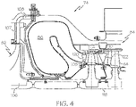
- a turbine is coupled to receive an axially directed core flow (flow may be directed radially in case of a radial turbine), of the combusted gas from the combustor to rotate a turbine rotor. Temperature and pressure of the combusted gas drops through the turbine.
- a turbine nozzle is disposed upstream from the turbine rotor and is configured to direct the combusted gas to the turbine rotor.
- a number of vanes are disposed in the turbine nozzle and the vanes are configured to vary a flow area through which the core flow passes. Opening and closing the vanes adjusts the pressure ratio of the engine to compensate for changing flow and turbine inlet requirements of the gas turbine engine. For example, while maintaining constant power output in a single spool gas turbine engine, moving the vanes in a closing direction increases the pressure-ratio of the core flow in the engine, reduces of the core flow, and requires an increase in turbine inlet temperature to maintain the same power output of the engine.
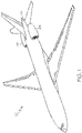
- an aircraft 20 includes a pair of turbine engines 22, 24, which are configured as turbofan engines configured to provide propulsion for the aircraft 20.
- the aircraft 20 also includes a turbine engine 26, which in this embodiment is configured as a part of an APU.
- turbine engines 22, 24, 26 are used with the aircraft 20, various other engine environments, as well as different types of turbine machinery will benefit from the features described herein.
- no particular feature or characteristic is constrained to an aircraft or to a particular application of a turbine, and the principles are equally embodied in other vehicles or in other equipment and in other applications.
- the turbine system described herein may be employed in a variety of applications, including in the engines 22, 24, 26 or other applications.
- the engine 22 will be described with reference to FIG. 2 .
- the engine 24 is similar to the engine 22.
- the engine 22 is configured as a gas turbine engine for aircraft propulsion.
- the engine 22 includes an intake 28, with a fan section 30 disposed in a fan case 32.
- the fan section 30 draws air into the engine 22, accelerates the air within the engine 22, and may assist in providing propulsion for the aircraft 20.
- the air is directed through two paths, a core flow into the engine core 34, and a bypass through a bypass duct 36.
Landscapes
- Engineering & Computer Science (AREA)
- Chemical & Material Sciences (AREA)
- Combustion & Propulsion (AREA)
- Mechanical Engineering (AREA)
- General Engineering & Computer Science (AREA)
- Physics & Mathematics (AREA)
- Fluid Mechanics (AREA)
- Control Of Turbines (AREA)
Claims (9)
- Système de distributeur de turbine à section variable (VATN = variable area turbine nozzle), comprenant :une turbine à gaz, comprenant :un compresseur conçu pour fournir de l'air comprimé ;une chambre de combustion conçue pour recevoir au moins une partie de l'air comprimé et un flux de combustible et pour générer un flux de gaz brûlé ;une turbine accouplée pour recevoir un flux central de gaz brûlé provenant de la chambre de combustion pour faire tourner un rotor de turbine ;une tuyère d'entrée de turbine disposée entre la chambre de combustion et le rotor de turbine et conçue pour diriger le gaz brûlé vers le rotor de turbine ; etun certain nombre d'aubes disposées dans la tuyère d'entrée de turbine ;un système d'entraînement (171) conçu pour faire tourner les aubes afin de faire varier une zone de flux à travers laquelle passe le flux central ; etun contrôleur, dans lequel le système d'entraînement et le contrôleur sont conçus pour ajuster un rapport de pression de la turbine à gaz pour compenser les exigences opérationnelles changeantes de la turbine à gaz en tournant vers des positions correspondant aux exigences opérationnelles changeantes ;dans lequel la turbine à gaz peut fonctionner à des altitudes variables ;le système d'entraînement et le contrôleur sont conçus pour maintenir une puissance nominale constante de la turbine à gaz tandis que l'altitude change en ouvrant de plus en plus les aubes à mesure que l'altitude augmente et en maintenant le flux central constant tandis que le rapport de pression de la turbine augmente avec l'augmentation de l'altitude pour maintenir la puissance nominale constante.
- Système de distributeur de turbine à section variable selon la revendication 1, comprenant :un second rotor de turbine disposé dans la turbine pour recevoir le flux central ;dans lequel le système d'entraînement et le contrôleur sont conçus de sorte que les aubes doivent s'ouvrir et se fermer pour ajuster un niveau de travail entre deux rotors de turbine en modifiant une chute de pression à travers au moins l'un des rotors de turbine et en étendant une plage de pression de fonctionnement de la turbine.
- Système de distributeur de turbine à section variable selon la revendication 1, comprenant :une tige reliée à chacune des aubes ;un engrenage de tige sur chaque tige ;une couronne dentée s'engrenant avec chaque engrenage et s'étendant autour de la turbine ;un engrenage d'entraînement s'engrenant avec la couronne dentée ; etun actionneur conçu pour faire tourner l'engrenage d'entraînement.
- Système de distributeur de turbine à section variable selon la revendication 3, comprenant :une section de boîtier définissant une ouverture ; etun support relié entre chaque tige et chaque aube, le support étant conçu pour tourner dans l'ouverture.
- Système de distributeur de turbine à section variable selon la revendication 1, dans lequel le système d'entraînement et le contrôleur sont conçus de sorte que les aubes augmentent un rapport de pression de la turbine à gaz par modulation de fermeture pour augmenter la sortie de puissance de la turbine.
- Système de distributeur de turbine à section variable selon la revendication 1, dans lequel le système d'entraînement et le contrôleur sont conçus de sorte que les aubes réduisent un paramètre de charge de la chambre de combustion en modulant vers une position complètement fermée pour démarrer la turbine à gaz en altitude.
- Système de distributeur de turbine à section variable selon la revendication 1, dans lequel le système d'entraînement et le contrôleur sont conçus de sorte que les aubes augmentent le débit central par modulation d'ouverture pour réduire la température d'entrée de la turbine.
- Procédé de fonctionnement d'une turbine à gaz qui comprend un compresseur, une chambre de combustion et une turbine alimentée en gaz de combustion provenant de la chambre de combustion à travers une tuyère d'entrée de turbine, le procédé comprenant :le positionnement d'un certain nombre d'aubes dans la tuyère d'entrée de turbine ;la rotation des aubes pour faire varier une zone de flux à travers laquelle passe le flux central ; etl'ajustement d'un rapport de pression de la turbine à gaz pour compenser les exigences opérationnelles changeantes de la turbine à gaz en faisant tourner les aubes vers une position correspondant aux exigences opérationnelles changeantes ;le fonctionnement de la turbine à gaz à différentes altitudes ;le maintien d'une puissance nominale constante de la turbine à gaz tandis que l'altitude change en ouvrant de plus en plus les aubes à mesure que l'altitude augmente ; etle maintien constant du flux central tandis que le rapport de pression de la turbine augmente avec l'augmentation de l'altitude pour maintenir la puissance nominale constante ;dans lequel la rotation des aubes est réalisée à l'aide d'un système d'entraînement.
- Procédé selon la revendication 8, comprenant :le positionnement d'un second rotor de turbine dans la turbine pour recevoir le flux central ; etle changement d'une chute de pression à travers au moins l'un des rotors de turbine en faisant tourner les aubes pour ajuster un niveau de travail entre deux rotors de turbine, en étendant une plage de pressions de fonctionnement de la turbine.
Applications Claiming Priority (1)
| Application Number | Priority Date | Filing Date | Title |
|---|---|---|---|
| US16/412,771 US11480111B2 (en) | 2019-05-15 | 2019-05-15 | Variable area turbine nozzle and method |
Publications (2)
| Publication Number | Publication Date |
|---|---|
| EP3739191A1 EP3739191A1 (fr) | 2020-11-18 |
| EP3739191B1 true EP3739191B1 (fr) | 2023-01-25 |
Family
ID=70736627
Family Applications (1)
| Application Number | Title | Priority Date | Filing Date |
|---|---|---|---|
| EP20174540.3A Active EP3739191B1 (fr) | 2019-05-15 | 2020-05-13 | Distributeur de turbine à section variable et procédé |
Country Status (2)
| Country | Link |
|---|---|
| US (1) | US11480111B2 (fr) |
| EP (1) | EP3739191B1 (fr) |
Families Citing this family (3)
| Publication number | Priority date | Publication date | Assignee | Title |
|---|---|---|---|---|
| US11867069B2 (en) * | 2021-06-28 | 2024-01-09 | Rtx Corporation | Hybrid electric variable area turbine |
| US12434849B2 (en) | 2021-08-06 | 2025-10-07 | Rtx Corporation | Energy optimization for a hybrid electric engine |
| GB2639854A (en) * | 2024-03-25 | 2025-10-08 | Rolls Royce Deutschland Ltd & Co Kg | Blocking mechanism for a gas turbine |
Family Cites Families (43)
| Publication number | Priority date | Publication date | Assignee | Title |
|---|---|---|---|---|
| US2608054A (en) | 1942-03-06 | 1952-08-26 | Lockheed Aircraft Corp | Air turbine starting means for gas turbine power plants |
| US2411895A (en) | 1944-04-15 | 1946-12-03 | United Aircraft Corp | Nozzle control |
| US2514393A (en) * | 1947-09-03 | 1950-07-11 | Westinghouse Electric Corp | Variable area exhaust nozzle for power plants |
| US2551229A (en) | 1949-10-14 | 1951-05-01 | Gen Electric | Variable area nozzle and fluid injection control for turbojet engines |
| US2791882A (en) | 1950-09-29 | 1957-05-14 | Westinghouse Electric Corp | Variable area nozzle for jet propulsion engine |
| US3060686A (en) | 1956-06-15 | 1962-10-30 | Garrett Corp | Augmented gas turbine engine and controls |
| FR1483743A (fr) * | 1965-12-02 | 1967-06-09 | Snecma | Turbomachine à compresseur contrarotatif |
| GB1313841A (en) * | 1967-01-18 | 1973-04-18 | Secr Defence | Gas turbine jet propulsion engine |
| DE1963432C3 (de) * | 1969-12-18 | 1979-03-22 | Motoren- Und Turbinen-Union Muenchen Gmbh, 8000 Muenchen | Regeleinrichtung für eine Gasturbinenanlage |
| US3834161A (en) * | 1973-06-01 | 1974-09-10 | Us Air Force | Dual mode auxiliary power unit |
| US5079916A (en) * | 1982-11-01 | 1992-01-14 | General Electric Company | Counter rotation power turbine |
| US4759178A (en) * | 1987-03-17 | 1988-07-26 | Williams International Corporation | Aircraft auxiliary power unit |
| US4912921A (en) * | 1988-03-14 | 1990-04-03 | Sundstrand Corporation | Low speed spool emergency power extraction system |
| US4932206A (en) | 1988-08-17 | 1990-06-12 | Sundstrand Corporation | Guide vane assembly for auxiliary power unit |
| GB2301868B (en) * | 1995-06-05 | 1999-08-11 | Rolls Royce Plc | Improved actuator mechanism for variable angle vane arrays |
| GB0002257D0 (en) * | 2000-02-02 | 2000-03-22 | Rolls Royce Plc | Rotary apparatus for a gas turbine engine |
| DE10202532C1 (de) | 2002-01-24 | 2003-05-08 | Porsche Ag | Luftaustrittsdüse für ein Fahrzeug |
| US7036321B2 (en) | 2003-10-08 | 2006-05-02 | Honeywell International, Inc. | Auxiliary power unit having a rotary fuel slinger |
| US7251942B2 (en) | 2004-06-29 | 2007-08-07 | Honeywell International Inc. | Integrated gearless and nonlubricated auxiliary power unit |
| US7089744B2 (en) | 2004-07-21 | 2006-08-15 | Steward Davis International, Inc. | Onboard supplemental power system at varying high altitudes |
| US7937945B2 (en) * | 2006-10-27 | 2011-05-10 | Kinde Sr Ronald August | Combining a series of more efficient engines into a unit, or modular units |
| US8007229B2 (en) * | 2007-05-24 | 2011-08-30 | United Technologies Corporation | Variable area turbine vane arrangement |
| US20100260591A1 (en) * | 2007-06-08 | 2010-10-14 | General Electric Company | Spanwise split variable guide vane and related method |
| GB0713951D0 (en) | 2007-07-18 | 2007-08-29 | Cummins Turbo Tech Ltd | Calibration of an actuator for a variable geometry turbine |
| US9701415B2 (en) | 2007-08-23 | 2017-07-11 | United Technologies Corporation | Gas turbine engine with axial movable fan variable area nozzle |
| JP4838785B2 (ja) * | 2007-11-06 | 2011-12-14 | 三菱重工業株式会社 | ガスタービンの運転制御装置および運転制御方法 |
| US8079217B2 (en) | 2008-11-24 | 2011-12-20 | Honeywell International Inc. | Turbocharger with variable turbine nozzle actuated by hydraulic and mechanical spring forces |
| US20110176913A1 (en) * | 2010-01-19 | 2011-07-21 | Stephen Paul Wassynger | Non-linear asymmetric variable guide vane schedule |
| FR2976018B1 (fr) | 2011-06-01 | 2014-12-05 | Turbomeca | Distributeur de turbine radiale a calage variable, en particulier de turbine de source de puissance auxiliaire |
| US8291690B1 (en) * | 2012-01-31 | 2012-10-23 | United Technologies Corporation | Gas turbine engine with variable area fan nozzle positioned for starting |
| US9957832B2 (en) * | 2012-02-28 | 2018-05-01 | United Technologies Corporation | Variable area turbine |
| US8862362B2 (en) | 2012-07-02 | 2014-10-14 | United Technologies Corporation | Scheduling of variable area fan nozzle to optimize engine performance |
| WO2014098276A1 (fr) | 2012-12-18 | 2014-06-26 | 한국항공우주연구원 | Appareil permettant d'empêcher un compresseur axial de caler au moyen d'un traitement de carter |
| US10364697B2 (en) | 2013-09-30 | 2019-07-30 | Borgwarner Inc. | Actuating mechanism and gear driven adjustment ring for a variable geometry turbocharger |
| US9863367B2 (en) | 2013-11-01 | 2018-01-09 | The Boeing Company | Fan nozzle drive systems that lock thrust reversers |
| US20150176530A1 (en) | 2013-12-19 | 2015-06-25 | United Technologies Corporation | Ultra high overall pessure ratio gas turbine engine |
| US10012102B2 (en) * | 2014-02-21 | 2018-07-03 | United Technologies Corporation | Variable vane synchronization ring transmission mechanism |
| GB201407314D0 (en) * | 2014-04-25 | 2014-06-11 | Rolls Royce Plc | Control of a gas turbine engine |
| GB2541185A (en) | 2015-08-07 | 2017-02-15 | Rolls Royce Plc | Auxiliary power unit assembly and a method of using the same |
| US10294813B2 (en) * | 2016-03-24 | 2019-05-21 | United Technologies Corporation | Geared unison ring for variable vane actuation |
| GB2558228B (en) * | 2016-12-22 | 2020-05-20 | Rolls Royce Plc | Aircraft electrically-assisted propulsion control system |
| US10208675B2 (en) | 2017-03-15 | 2019-02-19 | The Boeing Company | Hybrid drive system for transferring power from a gas turbine engine of an aircraft |
| US10981660B2 (en) * | 2018-04-19 | 2021-04-20 | The Boeing Company | Hybrid propulsion engines for aircraft |
-
2019
- 2019-05-15 US US16/412,771 patent/US11480111B2/en active Active
-
2020
- 2020-05-13 EP EP20174540.3A patent/EP3739191B1/fr active Active
Also Published As
| Publication number | Publication date |
|---|---|
| US20200362768A1 (en) | 2020-11-19 |
| EP3739191A1 (fr) | 2020-11-18 |
| US11480111B2 (en) | 2022-10-25 |
Similar Documents
| Publication | Publication Date | Title |
|---|---|---|
| CN108137162B (zh) | 具有可变速比的辅助动力单元 | |
| US11873766B2 (en) | Differential geared amplification of auxiliary power unit | |
| US20200309027A1 (en) | Gas turbine engine with an electromagnetic transmission | |
| EP2584173B1 (fr) | Moteur à turbine à gaz | |
| EP2584172B1 (fr) | Transmission à vitesse constante pour moteur à turbine à gaz | |
| US8978352B2 (en) | Apparatus and method for operating a gas turbine engine during windmilling | |
| EP2584168B1 (fr) | Système thermique intégré pour un moteur à turbine à gaz | |
| EP1574689B1 (fr) | Procédé et appareil pour l'opération d'une turbine à gaz | |
| US8117827B2 (en) | Apparatus for operating gas turbine engines | |
| CN103582742B (zh) | 用于径流式涡轮,特别是用于辅助动力源涡轮的可变斜度喷嘴 | |
| US8966876B2 (en) | Controllable speed windmill operation of a gas turbine engine through low spool power extraction | |
| US10859003B2 (en) | Control system for a gas turbine engine | |
| EP2982833B1 (fr) | Moteur a turbine a gaz | |
| EP3739191A1 (fr) | Distributeur de turbine à section variable et procédé | |
| US11015476B2 (en) | Electrical energy generating system | |
| US11339717B2 (en) | Environmental control system | |
| EP4187069A1 (fr) | Système de moteur multimode avec moteur à turbine à gaz et turbocompresseur |
Legal Events
| Date | Code | Title | Description |
|---|---|---|---|
| PUAI | Public reference made under article 153(3) epc to a published international application that has entered the european phase |
Free format text: ORIGINAL CODE: 0009012 |
|
| STAA | Information on the status of an ep patent application or granted ep patent |
Free format text: STATUS: THE APPLICATION HAS BEEN PUBLISHED |
|
| AK | Designated contracting states |
Kind code of ref document: A1 Designated state(s): AL AT BE BG CH CY CZ DE DK EE ES FI FR GB GR HR HU IE IS IT LI LT LU LV MC MK MT NL NO PL PT RO RS SE SI SK SM TR |
|
| AX | Request for extension of the european patent |
Extension state: BA ME |
|
| STAA | Information on the status of an ep patent application or granted ep patent |
Free format text: STATUS: REQUEST FOR EXAMINATION WAS MADE |
|
| 17P | Request for examination filed |
Effective date: 20210324 |
|
| RBV | Designated contracting states (corrected) |
Designated state(s): AL AT BE BG CH CY CZ DE DK EE ES FI FR GB GR HR HU IE IS IT LI LT LU LV MC MK MT NL NO PL PT RO RS SE SI SK SM TR |
|
| RAP3 | Party data changed (applicant data changed or rights of an application transferred) |
Owner name: HONEYWELL INTERNATIONAL INC. |
|
| RIC1 | Information provided on ipc code assigned before grant |
Ipc: F02C 9/54 20060101ALI20220722BHEP Ipc: F02C 9/22 20060101AFI20220722BHEP |
|
| GRAP | Despatch of communication of intention to grant a patent |
Free format text: ORIGINAL CODE: EPIDOSNIGR1 |
|
| STAA | Information on the status of an ep patent application or granted ep patent |
Free format text: STATUS: GRANT OF PATENT IS INTENDED |
|
| INTG | Intention to grant announced |
Effective date: 20220906 |
|
| GRAS | Grant fee paid |
Free format text: ORIGINAL CODE: EPIDOSNIGR3 |
|
| GRAA | (expected) grant |
Free format text: ORIGINAL CODE: 0009210 |
|
| STAA | Information on the status of an ep patent application or granted ep patent |
Free format text: STATUS: THE PATENT HAS BEEN GRANTED |
|
| AK | Designated contracting states |
Kind code of ref document: B1 Designated state(s): AL AT BE BG CH CY CZ DE DK EE ES FI FR GB GR HR HU IE IS IT LI LT LU LV MC MK MT NL NO PL PT RO RS SE SI SK SM TR |
|
| REG | Reference to a national code |
Ref country code: GB Ref legal event code: FG4D |
|
| REG | Reference to a national code |
Ref country code: CH Ref legal event code: EP |
|
| REG | Reference to a national code |
Ref country code: AT Ref legal event code: REF Ref document number: 1546066 Country of ref document: AT Kind code of ref document: T Effective date: 20230215 Ref country code: IE Ref legal event code: FG4D |
|
| REG | Reference to a national code |
Ref country code: DE Ref legal event code: R096 Ref document number: 602020007770 Country of ref document: DE |
|
| REG | Reference to a national code |
Ref country code: LT Ref legal event code: MG9D |
|
| REG | Reference to a national code |
Ref country code: NL Ref legal event code: MP Effective date: 20230125 |
|
| P01 | Opt-out of the competence of the unified patent court (upc) registered |
Effective date: 20230421 |
|
| REG | Reference to a national code |
Ref country code: AT Ref legal event code: MK05 Ref document number: 1546066 Country of ref document: AT Kind code of ref document: T Effective date: 20230125 |
|
| PG25 | Lapsed in a contracting state [announced via postgrant information from national office to epo] |
Ref country code: NL Free format text: LAPSE BECAUSE OF FAILURE TO SUBMIT A TRANSLATION OF THE DESCRIPTION OR TO PAY THE FEE WITHIN THE PRESCRIBED TIME-LIMIT Effective date: 20230125 |
|
| PG25 | Lapsed in a contracting state [announced via postgrant information from national office to epo] |
Ref country code: RS Free format text: LAPSE BECAUSE OF FAILURE TO SUBMIT A TRANSLATION OF THE DESCRIPTION OR TO PAY THE FEE WITHIN THE PRESCRIBED TIME-LIMIT Effective date: 20230125 Ref country code: PT Free format text: LAPSE BECAUSE OF FAILURE TO SUBMIT A TRANSLATION OF THE DESCRIPTION OR TO PAY THE FEE WITHIN THE PRESCRIBED TIME-LIMIT Effective date: 20230525 Ref country code: NO Free format text: LAPSE BECAUSE OF FAILURE TO SUBMIT A TRANSLATION OF THE DESCRIPTION OR TO PAY THE FEE WITHIN THE PRESCRIBED TIME-LIMIT Effective date: 20230425 Ref country code: LV Free format text: LAPSE BECAUSE OF FAILURE TO SUBMIT A TRANSLATION OF THE DESCRIPTION OR TO PAY THE FEE WITHIN THE PRESCRIBED TIME-LIMIT Effective date: 20230125 Ref country code: LT Free format text: LAPSE BECAUSE OF FAILURE TO SUBMIT A TRANSLATION OF THE DESCRIPTION OR TO PAY THE FEE WITHIN THE PRESCRIBED TIME-LIMIT Effective date: 20230125 Ref country code: HR Free format text: LAPSE BECAUSE OF FAILURE TO SUBMIT A TRANSLATION OF THE DESCRIPTION OR TO PAY THE FEE WITHIN THE PRESCRIBED TIME-LIMIT Effective date: 20230125 Ref country code: ES Free format text: LAPSE BECAUSE OF FAILURE TO SUBMIT A TRANSLATION OF THE DESCRIPTION OR TO PAY THE FEE WITHIN THE PRESCRIBED TIME-LIMIT Effective date: 20230125 Ref country code: AT Free format text: LAPSE BECAUSE OF FAILURE TO SUBMIT A TRANSLATION OF THE DESCRIPTION OR TO PAY THE FEE WITHIN THE PRESCRIBED TIME-LIMIT Effective date: 20230125 |
|
| PG25 | Lapsed in a contracting state [announced via postgrant information from national office to epo] |
Ref country code: SE Free format text: LAPSE BECAUSE OF FAILURE TO SUBMIT A TRANSLATION OF THE DESCRIPTION OR TO PAY THE FEE WITHIN THE PRESCRIBED TIME-LIMIT Effective date: 20230125 Ref country code: PL Free format text: LAPSE BECAUSE OF FAILURE TO SUBMIT A TRANSLATION OF THE DESCRIPTION OR TO PAY THE FEE WITHIN THE PRESCRIBED TIME-LIMIT Effective date: 20230125 Ref country code: IS Free format text: LAPSE BECAUSE OF FAILURE TO SUBMIT A TRANSLATION OF THE DESCRIPTION OR TO PAY THE FEE WITHIN THE PRESCRIBED TIME-LIMIT Effective date: 20230525 Ref country code: GR Free format text: LAPSE BECAUSE OF FAILURE TO SUBMIT A TRANSLATION OF THE DESCRIPTION OR TO PAY THE FEE WITHIN THE PRESCRIBED TIME-LIMIT Effective date: 20230426 Ref country code: FI Free format text: LAPSE BECAUSE OF FAILURE TO SUBMIT A TRANSLATION OF THE DESCRIPTION OR TO PAY THE FEE WITHIN THE PRESCRIBED TIME-LIMIT Effective date: 20230125 |
|
| REG | Reference to a national code |
Ref country code: DE Ref legal event code: R097 Ref document number: 602020007770 Country of ref document: DE |
|
| PG25 | Lapsed in a contracting state [announced via postgrant information from national office to epo] |
Ref country code: SM Free format text: LAPSE BECAUSE OF FAILURE TO SUBMIT A TRANSLATION OF THE DESCRIPTION OR TO PAY THE FEE WITHIN THE PRESCRIBED TIME-LIMIT Effective date: 20230125 Ref country code: RO Free format text: LAPSE BECAUSE OF FAILURE TO SUBMIT A TRANSLATION OF THE DESCRIPTION OR TO PAY THE FEE WITHIN THE PRESCRIBED TIME-LIMIT Effective date: 20230125 Ref country code: EE Free format text: LAPSE BECAUSE OF FAILURE TO SUBMIT A TRANSLATION OF THE DESCRIPTION OR TO PAY THE FEE WITHIN THE PRESCRIBED TIME-LIMIT Effective date: 20230125 Ref country code: DK Free format text: LAPSE BECAUSE OF FAILURE TO SUBMIT A TRANSLATION OF THE DESCRIPTION OR TO PAY THE FEE WITHIN THE PRESCRIBED TIME-LIMIT Effective date: 20230125 Ref country code: CZ Free format text: LAPSE BECAUSE OF FAILURE TO SUBMIT A TRANSLATION OF THE DESCRIPTION OR TO PAY THE FEE WITHIN THE PRESCRIBED TIME-LIMIT Effective date: 20230125 |
|
| PG25 | Lapsed in a contracting state [announced via postgrant information from national office to epo] |
Ref country code: SK Free format text: LAPSE BECAUSE OF FAILURE TO SUBMIT A TRANSLATION OF THE DESCRIPTION OR TO PAY THE FEE WITHIN THE PRESCRIBED TIME-LIMIT Effective date: 20230125 |
|
| PLBE | No opposition filed within time limit |
Free format text: ORIGINAL CODE: 0009261 |
|
| REG | Reference to a national code |
Ref country code: DE Ref legal event code: R119 Ref document number: 602020007770 Country of ref document: DE |
|
| STAA | Information on the status of an ep patent application or granted ep patent |
Free format text: STATUS: NO OPPOSITION FILED WITHIN TIME LIMIT |
|
| REG | Reference to a national code |
Ref country code: CH Ref legal event code: PL |
|
| 26N | No opposition filed |
Effective date: 20231026 |
|
| PG25 | Lapsed in a contracting state [announced via postgrant information from national office to epo] |
Ref country code: MC Free format text: LAPSE BECAUSE OF FAILURE TO SUBMIT A TRANSLATION OF THE DESCRIPTION OR TO PAY THE FEE WITHIN THE PRESCRIBED TIME-LIMIT Effective date: 20230125 |
|
| REG | Reference to a national code |
Ref country code: BE Ref legal event code: MM Effective date: 20230531 |
|
| PG25 | Lapsed in a contracting state [announced via postgrant information from national office to epo] |
Ref country code: SI Free format text: LAPSE BECAUSE OF FAILURE TO SUBMIT A TRANSLATION OF THE DESCRIPTION OR TO PAY THE FEE WITHIN THE PRESCRIBED TIME-LIMIT Effective date: 20230125 Ref country code: MC Free format text: LAPSE BECAUSE OF FAILURE TO SUBMIT A TRANSLATION OF THE DESCRIPTION OR TO PAY THE FEE WITHIN THE PRESCRIBED TIME-LIMIT Effective date: 20230125 Ref country code: LU Free format text: LAPSE BECAUSE OF NON-PAYMENT OF DUE FEES Effective date: 20230513 Ref country code: LI Free format text: LAPSE BECAUSE OF NON-PAYMENT OF DUE FEES Effective date: 20230531 Ref country code: CH Free format text: LAPSE BECAUSE OF NON-PAYMENT OF DUE FEES Effective date: 20230531 |
|
| REG | Reference to a national code |
Ref country code: IE Ref legal event code: MM4A |
|
| PG25 | Lapsed in a contracting state [announced via postgrant information from national office to epo] |
Ref country code: IE Free format text: LAPSE BECAUSE OF NON-PAYMENT OF DUE FEES Effective date: 20230513 |
|
| PG25 | Lapsed in a contracting state [announced via postgrant information from national office to epo] |
Ref country code: IE Free format text: LAPSE BECAUSE OF NON-PAYMENT OF DUE FEES Effective date: 20230513 Ref country code: DE Free format text: LAPSE BECAUSE OF NON-PAYMENT OF DUE FEES Effective date: 20231201 |
|
| PG25 | Lapsed in a contracting state [announced via postgrant information from national office to epo] |
Ref country code: IT Free format text: LAPSE BECAUSE OF FAILURE TO SUBMIT A TRANSLATION OF THE DESCRIPTION OR TO PAY THE FEE WITHIN THE PRESCRIBED TIME-LIMIT Effective date: 20230125 Ref country code: BE Free format text: LAPSE BECAUSE OF NON-PAYMENT OF DUE FEES Effective date: 20230531 |
|
| PG25 | Lapsed in a contracting state [announced via postgrant information from national office to epo] |
Ref country code: BG Free format text: LAPSE BECAUSE OF FAILURE TO SUBMIT A TRANSLATION OF THE DESCRIPTION OR TO PAY THE FEE WITHIN THE PRESCRIBED TIME-LIMIT Effective date: 20230125 |
|
| PG25 | Lapsed in a contracting state [announced via postgrant information from national office to epo] |
Ref country code: BG Free format text: LAPSE BECAUSE OF FAILURE TO SUBMIT A TRANSLATION OF THE DESCRIPTION OR TO PAY THE FEE WITHIN THE PRESCRIBED TIME-LIMIT Effective date: 20230125 |
|
| GBPC | Gb: european patent ceased through non-payment of renewal fee |
Effective date: 20240513 |
|
| PG25 | Lapsed in a contracting state [announced via postgrant information from national office to epo] |
Ref country code: GB Free format text: LAPSE BECAUSE OF NON-PAYMENT OF DUE FEES Effective date: 20240513 |
|
| PGFP | Annual fee paid to national office [announced via postgrant information from national office to epo] |
Ref country code: FR Payment date: 20250526 Year of fee payment: 6 |
|
| PG25 | Lapsed in a contracting state [announced via postgrant information from national office to epo] |
Ref country code: CY Free format text: LAPSE BECAUSE OF FAILURE TO SUBMIT A TRANSLATION OF THE DESCRIPTION OR TO PAY THE FEE WITHIN THE PRESCRIBED TIME-LIMIT; INVALID AB INITIO Effective date: 20200513 |
|
| PG25 | Lapsed in a contracting state [announced via postgrant information from national office to epo] |
Ref country code: HU Free format text: LAPSE BECAUSE OF FAILURE TO SUBMIT A TRANSLATION OF THE DESCRIPTION OR TO PAY THE FEE WITHIN THE PRESCRIBED TIME-LIMIT; INVALID AB INITIO Effective date: 20200513 |
|
| PG25 | Lapsed in a contracting state [announced via postgrant information from national office to epo] |
Ref country code: TR Free format text: LAPSE BECAUSE OF FAILURE TO SUBMIT A TRANSLATION OF THE DESCRIPTION OR TO PAY THE FEE WITHIN THE PRESCRIBED TIME-LIMIT Effective date: 20230125 |