EP3739224B1 - Agencement de palier d'une éolienne et éolienne - Google Patents
Agencement de palier d'une éolienne et éolienne Download PDFInfo
- Publication number
- EP3739224B1 EP3739224B1 EP19174858.1A EP19174858A EP3739224B1 EP 3739224 B1 EP3739224 B1 EP 3739224B1 EP 19174858 A EP19174858 A EP 19174858A EP 3739224 B1 EP3739224 B1 EP 3739224B1
- Authority
- EP
- European Patent Office
- Prior art keywords
- bearing
- radial
- cylindrical seat
- arrangement
- drive shaft
- Prior art date
- Legal status (The legal status is an assumption and is not a legal conclusion. Google has not performed a legal analysis and makes no representation as to the accuracy of the status listed.)
- Active
Links
Images


Classifications
-
- F—MECHANICAL ENGINEERING; LIGHTING; HEATING; WEAPONS; BLASTING
- F16—ENGINEERING ELEMENTS AND UNITS; GENERAL MEASURES FOR PRODUCING AND MAINTAINING EFFECTIVE FUNCTIONING OF MACHINES OR INSTALLATIONS; THERMAL INSULATION IN GENERAL
- F16C—SHAFTS; FLEXIBLE SHAFTS; ELEMENTS OR CRANKSHAFT MECHANISMS; ROTARY BODIES OTHER THAN GEARING ELEMENTS; BEARINGS
- F16C17/00—Sliding-contact bearings for exclusively rotary movement
- F16C17/26—Systems consisting of a plurality of sliding-contact bearings
-
- F—MECHANICAL ENGINEERING; LIGHTING; HEATING; WEAPONS; BLASTING
- F16—ENGINEERING ELEMENTS AND UNITS; GENERAL MEASURES FOR PRODUCING AND MAINTAINING EFFECTIVE FUNCTIONING OF MACHINES OR INSTALLATIONS; THERMAL INSULATION IN GENERAL
- F16C—SHAFTS; FLEXIBLE SHAFTS; ELEMENTS OR CRANKSHAFT MECHANISMS; ROTARY BODIES OTHER THAN GEARING ELEMENTS; BEARINGS
- F16C17/00—Sliding-contact bearings for exclusively rotary movement
- F16C17/02—Sliding-contact bearings for exclusively rotary movement for radial load only
- F16C17/03—Sliding-contact bearings for exclusively rotary movement for radial load only with tiltably-supported segments, e.g. Michell bearings
-
- F—MECHANICAL ENGINEERING; LIGHTING; HEATING; WEAPONS; BLASTING
- F03—MACHINES OR ENGINES FOR LIQUIDS; WIND, SPRING, OR WEIGHT MOTORS; PRODUCING MECHANICAL POWER OR A REACTIVE PROPULSIVE THRUST, NOT OTHERWISE PROVIDED FOR
- F03D—WIND MOTORS
- F03D80/00—Details, components or accessories not provided for in groups F03D1/00 - F03D17/00
- F03D80/70—Bearing or lubricating arrangements
-
- F—MECHANICAL ENGINEERING; LIGHTING; HEATING; WEAPONS; BLASTING
- F16—ENGINEERING ELEMENTS AND UNITS; GENERAL MEASURES FOR PRODUCING AND MAINTAINING EFFECTIVE FUNCTIONING OF MACHINES OR INSTALLATIONS; THERMAL INSULATION IN GENERAL
- F16C—SHAFTS; FLEXIBLE SHAFTS; ELEMENTS OR CRANKSHAFT MECHANISMS; ROTARY BODIES OTHER THAN GEARING ELEMENTS; BEARINGS
- F16C27/00—Elastic or yielding bearings or bearing supports, for exclusively rotary movement
- F16C27/02—Sliding-contact bearings
-
- F—MECHANICAL ENGINEERING; LIGHTING; HEATING; WEAPONS; BLASTING
- F16—ENGINEERING ELEMENTS AND UNITS; GENERAL MEASURES FOR PRODUCING AND MAINTAINING EFFECTIVE FUNCTIONING OF MACHINES OR INSTALLATIONS; THERMAL INSULATION IN GENERAL
- F16C—SHAFTS; FLEXIBLE SHAFTS; ELEMENTS OR CRANKSHAFT MECHANISMS; ROTARY BODIES OTHER THAN GEARING ELEMENTS; BEARINGS
- F16C33/00—Parts of bearings; Special methods for making bearings or parts thereof
- F16C33/02—Parts of sliding-contact bearings
- F16C33/04—Brasses; Bushes; Linings
- F16C33/06—Sliding surface mainly made of metal
- F16C33/10—Construction relative to lubrication
- F16C33/1025—Construction relative to lubrication with liquid, e.g. oil, as lubricant
- F16C33/106—Details of distribution or circulation inside the bearings, e.g. details of the bearing surfaces to affect flow or pressure of the liquid
- F16C33/108—Details of distribution or circulation inside the bearings, e.g. details of the bearing surfaces to affect flow or pressure of the liquid with a plurality of elements forming the bearing surfaces, e.g. bearing pads
-
- F—MECHANICAL ENGINEERING; LIGHTING; HEATING; WEAPONS; BLASTING
- F16—ENGINEERING ELEMENTS AND UNITS; GENERAL MEASURES FOR PRODUCING AND MAINTAINING EFFECTIVE FUNCTIONING OF MACHINES OR INSTALLATIONS; THERMAL INSULATION IN GENERAL
- F16C—SHAFTS; FLEXIBLE SHAFTS; ELEMENTS OR CRANKSHAFT MECHANISMS; ROTARY BODIES OTHER THAN GEARING ELEMENTS; BEARINGS
- F16C41/00—Other accessories, e.g. devices integrated in the bearing not relating to the bearing function as such
-
- F—MECHANICAL ENGINEERING; LIGHTING; HEATING; WEAPONS; BLASTING
- F05—INDEXING SCHEMES RELATING TO ENGINES OR PUMPS IN VARIOUS SUBCLASSES OF CLASSES F01-F04
- F05B—INDEXING SCHEME RELATING TO WIND, SPRING, WEIGHT, INERTIA OR LIKE MOTORS, TO MACHINES OR ENGINES FOR LIQUIDS COVERED BY SUBCLASSES F03B, F03D AND F03G
- F05B2240/00—Components
- F05B2240/50—Bearings
- F05B2240/53—Hydrodynamic or hydrostatic bearings
-
- F—MECHANICAL ENGINEERING; LIGHTING; HEATING; WEAPONS; BLASTING
- F05—INDEXING SCHEMES RELATING TO ENGINES OR PUMPS IN VARIOUS SUBCLASSES OF CLASSES F01-F04
- F05B—INDEXING SCHEME RELATING TO WIND, SPRING, WEIGHT, INERTIA OR LIKE MOTORS, TO MACHINES OR ENGINES FOR LIQUIDS COVERED BY SUBCLASSES F03B, F03D AND F03G
- F05B2240/00—Components
- F05B2240/50—Bearings
- F05B2240/54—Radial bearings
-
- F—MECHANICAL ENGINEERING; LIGHTING; HEATING; WEAPONS; BLASTING
- F16—ENGINEERING ELEMENTS AND UNITS; GENERAL MEASURES FOR PRODUCING AND MAINTAINING EFFECTIVE FUNCTIONING OF MACHINES OR INSTALLATIONS; THERMAL INSULATION IN GENERAL
- F16C—SHAFTS; FLEXIBLE SHAFTS; ELEMENTS OR CRANKSHAFT MECHANISMS; ROTARY BODIES OTHER THAN GEARING ELEMENTS; BEARINGS
- F16C2226/00—Joining parts; Fastening; Assembling or mounting parts
- F16C2226/10—Force connections, e.g. clamping
- F16C2226/14—Force connections, e.g. clamping by shrink fit, i.e. heating and shrinking part to allow assembly
-
- F—MECHANICAL ENGINEERING; LIGHTING; HEATING; WEAPONS; BLASTING
- F16—ENGINEERING ELEMENTS AND UNITS; GENERAL MEASURES FOR PRODUCING AND MAINTAINING EFFECTIVE FUNCTIONING OF MACHINES OR INSTALLATIONS; THERMAL INSULATION IN GENERAL
- F16C—SHAFTS; FLEXIBLE SHAFTS; ELEMENTS OR CRANKSHAFT MECHANISMS; ROTARY BODIES OTHER THAN GEARING ELEMENTS; BEARINGS
- F16C2226/00—Joining parts; Fastening; Assembling or mounting parts
- F16C2226/50—Positive connections
- F16C2226/70—Positive connections with complementary interlocking parts
- F16C2226/76—Positive connections with complementary interlocking parts with tongue and groove or key and slot
-
- F—MECHANICAL ENGINEERING; LIGHTING; HEATING; WEAPONS; BLASTING
- F16—ENGINEERING ELEMENTS AND UNITS; GENERAL MEASURES FOR PRODUCING AND MAINTAINING EFFECTIVE FUNCTIONING OF MACHINES OR INSTALLATIONS; THERMAL INSULATION IN GENERAL
- F16C—SHAFTS; FLEXIBLE SHAFTS; ELEMENTS OR CRANKSHAFT MECHANISMS; ROTARY BODIES OTHER THAN GEARING ELEMENTS; BEARINGS
- F16C2300/00—Application independent of particular apparatuses
- F16C2300/10—Application independent of particular apparatuses related to size
- F16C2300/14—Large applications, e.g. bearings having an inner diameter exceeding 500 mm
-
- F—MECHANICAL ENGINEERING; LIGHTING; HEATING; WEAPONS; BLASTING
- F16—ENGINEERING ELEMENTS AND UNITS; GENERAL MEASURES FOR PRODUCING AND MAINTAINING EFFECTIVE FUNCTIONING OF MACHINES OR INSTALLATIONS; THERMAL INSULATION IN GENERAL
- F16C—SHAFTS; FLEXIBLE SHAFTS; ELEMENTS OR CRANKSHAFT MECHANISMS; ROTARY BODIES OTHER THAN GEARING ELEMENTS; BEARINGS
- F16C2360/00—Engines or pumps
- F16C2360/31—Wind motors
-
- F—MECHANICAL ENGINEERING; LIGHTING; HEATING; WEAPONS; BLASTING
- F16—ENGINEERING ELEMENTS AND UNITS; GENERAL MEASURES FOR PRODUCING AND MAINTAINING EFFECTIVE FUNCTIONING OF MACHINES OR INSTALLATIONS; THERMAL INSULATION IN GENERAL
- F16C—SHAFTS; FLEXIBLE SHAFTS; ELEMENTS OR CRANKSHAFT MECHANISMS; ROTARY BODIES OTHER THAN GEARING ELEMENTS; BEARINGS
- F16C33/00—Parts of bearings; Special methods for making bearings or parts thereof
- F16C33/02—Parts of sliding-contact bearings
- F16C33/04—Brasses; Bushes; Linings
- F16C33/06—Sliding surface mainly made of metal
- F16C33/08—Attachment of brasses, bushes or linings to the bearing housing
-
- Y—GENERAL TAGGING OF NEW TECHNOLOGICAL DEVELOPMENTS; GENERAL TAGGING OF CROSS-SECTIONAL TECHNOLOGIES SPANNING OVER SEVERAL SECTIONS OF THE IPC; TECHNICAL SUBJECTS COVERED BY FORMER USPC CROSS-REFERENCE ART COLLECTIONS [XRACs] AND DIGESTS
- Y02—TECHNOLOGIES OR APPLICATIONS FOR MITIGATION OR ADAPTATION AGAINST CLIMATE CHANGE
- Y02E—REDUCTION OF GREENHOUSE GAS [GHG] EMISSIONS, RELATED TO ENERGY GENERATION, TRANSMISSION OR DISTRIBUTION
- Y02E10/00—Energy generation through renewable energy sources
- Y02E10/70—Wind energy
- Y02E10/72—Wind turbines with rotation axis in wind direction
Definitions
- the invention relates to a bearing arrangement for a wind turbine and a wind turbine.
- bearing arrangements of wind turbines comprise a bearing housing and a drive shaft, whereby the drive shaft is arranged within the bearing housing in an axial direction along a longitudinal axis of the bearing housing.
- Bearings of the bearing arrangement are arranged about the drive shaft, so that the drive shaft can be rotated within the bearing housing by means of a rotor of the wind turbine.
- Such a bearing arrangement is known from EP 3 276 192 A1 , for example.
- Such a bearing may be a radial fluid bearing comprising multiple radial bearing bodies, multiple radial tiltable support structures secured to the multiple radial bearing bodies, whereby each one of a multiple of radial bearing pads is attached to one of the multiple radial tiltable support structures.
- the radial bearing pads must be securely locked in place with respect to the cylindrical seat.
- using for example bolts for securing the radial bearing bodies to the cylindrical seat or bearing housing may be disadvantageous.
- First, many loose parts are introduced into the radial fluid bearing when using a bolt connection.
- the bolt connection may loosen up over time and require retightening.
- Third, the assembly space in the radial fluid bearing is very small and thus assembly of the radial fluid bearing as well as retightening a bolt connection is very cumbersome.
- the invention relates to a bearing arrangement for a wind turbine comprising a bearing housing and a drive shaft, whereby the drive shaft is arranged within the bearing housing in an axial direction along a longitudinal axis of the bearing housing, the bearing arrangement further comprising a downwind bearing and an upwind bearing, whereby the downwind bearing and the upwind bearing are arranged between the bearing housing and the drive shaft, wherein the downwind bearing and/or the upwind bearing is a radial fluid bearing comprising multiple radial bearing pads, whereby each one of the multiple radial bearing pads is attached to one of a multiple radial bearing bodies of the radial fluid bearing and the multiple radial bearing pads are arranged about the drive shaft, whereby the multiple bearing bodies are arranged adjacent to one another along a circumference of a cylindrical seat of the bearing housing, whereby adjacent bearing bodies are locked in movement relative to one another and relative to the cylindrical seat by means of a press-fitted locking piece, the locking piece providing a dovetail connection with the cylindrical
- the radial fluid bearing with its radial bearing pads is arranged in the bearing housing in a secure and simple manner.
- the assembly of the bearing arrangement with its radial fluid bearing according to the proposed invention does require only little assembly space, is practically free of maintenance and does not have loose parts.
- the multiple radial tiltable support structures allow for the multiple radial bearing pads to be tiltable with respect to the drive shaft. Thereby, tolerances between the drive shaft and the radial bearing pads can be compensated for.
- the downwind bearing is in particular arranged about a downwind portion of the drive shaft.
- the upwind bearing is in particular arranged about an upwind portion of the drive shaft.
- the downwind bearing may alternatively be referred to as a back-end bearing arranged about a back-end portion of the drive shaft.
- the upwind bearing may alternatively be referred to as a front-end bearing arranged about a front-end portion of the drive shaft. In a wind turbine, the front-end of the drive shaft is located closer to the rotor than its back-end.
- the locking pieces protrude above the adjacent bearing bodies.
- the locking pieces may protrude in such a way above the adjacent bearing bodies that there is a space between the locking pieces and the bearing bodies. By means of the thereby introduced space, further locking of the bearing bodies can be facilitated.
- the locking pieces intrude into the cylindrical seat.
- the locking pieces may, for example, be arranged in grooves of the cylindrical seat.
- the locking pieces may than also be referred to as slide-in locking pieces as they can be easily slid into the groove of the cylindrical seat in an axial direction along the longitudinal axis of the bearing housing.
- the locking pieces provide dovetail connections with the cylindrical seat.
- grooves in the cylindrical seat may have one or more undercuts for providing the dovetail connection and thereby safely securing the locking pieces in the cylindrical seat.
- bottom portions of the locking pieces are extending in tangential directions along the circumference of the cylindrical seat.
- undercuts in grooves may extend in a tangential direction of the circumference of the cylindrical seat.
- the bottom portions of the locking pieces may be arranged within these grooves or undercuts so that a particularly stable locking connection is provided.
- At least one of the locking pieces is a T-bar element or an I-bar element.
- all locking pieces may be T-bar and/or I-bar elements.
- T-bar elements substantially have the shape of a T
- I-bar elements substantially have the shape of an I when viewed along an axial direction along the longitudinal axis of the bearing housing. These shapes are particularly preferred as they provide good interlocking.
- the T-bar element or the I-bar element is made from a rigid material.
- the rigid material may be a metal, for example.
- the T-bar element or the I-bar element can withstand the high forces that act upon it without failure.
- At least one spring element is arranged between the at least one of the locking pieces and one of the adjacent radial bearing bodies.
- the at least one spring element may be in particular arranged between an upper part of the locking piece and a top surface of the one radial bearing body.
- two spring elements may be arranged between the at least one of the locking pieces and one of the adjacent radial bearing bodies.
- the two spring elements preferably are separated from one another, in particular by means of the locking piece which is arranged in between the two spring elements.
- the spring elements support the locking pieces in locking the radial bearing bodies against the cylindrical seat in a radial direction by providing pretension.
- the radial direction is a direction from the cylindrical seat to the drive shaft.
- a rigid element is arranged between the at least one spring element and the at least one of the adjacent bearing bodies.
- the rigid element may be made from metal, for example.
- the spring characteristic of the spring element can be adapted.
- the spring element is an elastomer.
- the elastomer can be implemented and exchanged between the locking piece and bearing body in a simple way.
- the locking piece comprises a stop plate arranged against a rim of the cylindrical seat in an axial direction along the longitudinal axis.
- the stop plate may be connected to the rim of the cylindrical seat by means of bolts, for example. Thereby, the movement of the bearing bodies in an axial direction along the longitudinal axis is locked.
- At least one wear protection element is arranged between at least one of the locking pieces and the cylindrical seat or a radial bearing body.
- at least two wear protection elements may be arranged between the locking pieces and the cylindrical seat, whereby the wear protection elements are separated from one another by means of the locking pieces.
- at least two wear protection elements may be arranged between the locking pieces and the radial bearing bodies, whereby the wear protection elements are separated from one another by means of the locking pieces and each one of the at least two wear protection elements is in contact with only one of the radial bearing bodies.
- the wear protection elements may comprise or be made from a polymer, in particular a thermosetting polymer. The wear protection elements reduce the risk of fretting of the locking piece.
- Each one of the multiple radial bearing pads is attached to one of the multiple radial bearing bodies by means of a radial tiltable support structure, whereby in particular the radial tiltable support structure is connected to at least one of the multiple radial bearing bodies by means of a spring connection.
- At least one of the multiple radial tiltable support structures may comprise a ball head.
- the ball head can provide a tilting functionality for compensation of tolerances in the radial fluid bearing.
- the at least one of the multiple radial bearing bodies securing the at least one of the multiple radial tiltable support structures comprising the ball head may comprise a ball socket for the ball head.
- the cylindrical seat may be formed in the bearing housing.
- the cylindrical seat may be formed by an inner shell surface of the bearing housing.
- the cylindrical seat may be integrally formed, in particular monolithically designed, with the bearing housing. Thereby, the cylindrical seat of the radial fluid bearing is stably provided at the bearing housing.
- At least one curved interface plate may be attached to at least one of the multiple radial bearing bodies opposite of the radial bearing pad, whereby the interface plate is arranged in contact with the cylindrical seat of the radial fluid bearing.
- the radial bearing pads are arranged with respect to the drive shaft with very little tolerances and at low cost with respect to manufacture and assembly.
- a curved interface plate may be attached to each one of the multiple radial bearing bodies opposite of the radial bearing pad, whereby the interface plates are arranged in contact with a cylindrical seat of the radial fluid bearing.
- a first interface plate side of the at least one interface plate, which is contact with the cylindrical seat, may have a curvature corresponding to a curvature of the cylindrical seat.
- the interface plate may be provided with a large contact surface contacting the cylindrical seat, whereby the stability of the radial fluid bearing is improved.
- a second interface plate side of the at least one interface plate which is located opposite of the first interface plate, may be predominantly plain or plain. Predominantly in this sense means that more than half of the surface of the second interface plate side is plain. Thereby, attachment of the radial bearing body to the interface plate may be facilitated.
- At least one of the at least one interface plate may comprise at least one interface plate attachment means for attaching the at least one interface plate to the at least one of the multiple radial bearing bodies.
- the at least one of the multiple radial bearing bodies may comprise a corresponding radial bearing body attachment means.
- the interface plate attachment means and the corresponding radial bearing body attachment means may be attached to each other by a further attachment means element. Thereby, the interface plate may be securely attached to radial bearing body.
- At least one of the at least one interface plate attachment means may be an interface plate through hole.
- the interface plate through hole may comprise threads, for example.
- a radial bearing body attachment means may further be a radial bearing body through hole, which also may comprise threads.
- An attachment means element may be a bolt, in particular a threaded bolt, for example.
- the invention relates to a wind turbine comprising a bearing arrangement according to the invention, whereby the wind turbine further comprises a rotor connected to drive the drive shaft and a generator connected to be driven by the drive shaft.
- the generator may be a direct drive generator or a geared generator having a gearbox, for example.
- the rotor is also commonly referred to as a hub of the wind turbine. Two, three or more wind turbine blades may be attached to the rotor or hub.
- the wind turbine may further comprise a nacelle, which may be supported on a tower of the wind turbine.
- the nacelle may comprise the bearing arrangement. The bearing arrangement, in particular the bearing housing, and the generator may be attached to the nacelle and/or the tower.
- FIG. 1 to 11 Same objects in FIG. 1 to 11 are denominated with the same reference number. If there is more than one object of the same kind in one of the figures, the objects are numbered in ascending order with the ascending number of the object being separated from its reference number by a dot.
- the specific dimensions of features and parts in the figures are exemplary and may be enlarged for ease of reference only.
- FIG. 1 shows a side view on a wind turbine 10.
- the wind turbine 10 comprises a supporting tower 20 and a nacelle 30, whereby the nacelle 30 is attached to the supporting tower 20.
- the nacelle 30 comprises a bearing arrangement 70, which is not shown in FIG. 1 but can be seen in FIG. 2 .
- the wind turbine 10 further comprises a generator 40 attached to a rotor 50 of the wind turbine 10. Two wind turbine blades 60.1, 60.2 are attached to the rotor 50.
- FIG. 2 shows a side perspective view on a sectional cut along the longitudinal axis A of the bearing arrangement 70 of the wind turbine 10 of FIG. 1 .
- the bearing arrangement 70 comprises a bearing housing 80 and a drive shaft 90, whereby the drive shaft 90 is arranged within the bearing housing 80 in an axial direction along the longitudinal axis A of the bearing housing 80 as indicated in FIG. 2 .
- the longitudinal axis A of the bearing housing 80 corresponds to the longitudinal axis A of the drive shaft 90 and thereby is a longitudinal axis A of the bearing arrangement 70.
- the bearing arrangement 90 further comprises a downwind bearing 100 and an upwind bearing 200 as radial fluid bearings, whereby the downwind bearing 100 and the upwind bearing 200 are arranged between the bearing housing 80 and the drive shaft 90.
- the downwind bearing 100 is arranged about a downwind portion of the drive shaft 90 and the upwind bearing 200 is arranged about an upwind portion of the drive shaft 90.
- the drive shaft 90 is operatively connected to the generator 40.
- the generator 40 is shown as a direct drive generator. However, it is also possible to provide the generator 40 as a geared generator, for example.
- FIG. 3 shows a side view on a sectional cut along the longitudinal axis A of the bearing arrangement 70 of FIG. 2 .
- An internal space 82 of the bearing housing 80 is formed between the bearing housing 80 and the drive shaft 90.
- Lubricant may leak from the downwind bearing 100 and the upwind bearing 200 into the internal space 82 and thereby be collected in the bearing housing 80, which is formed as a funnel 85 in a bottom part of the bearing housing 80.
- a lubricant pump 88 is fluidically connected to a drain outlet (not shown) of the bearing housing 80.
- the downwind bearing 100 comprising a lubricant flooded chamber 101
- the upwind bearing 200 comprising a lubricant flooded chamber 201 are shown, the principle and features of which will further be explained with reference to FIG. 4 and FIG. 5 .
- FIG. 4 shows an enlarged view on the sectional cut through the upwind bearing 200 and its lubricant flooded chamber 201 according to the detail IV of FIG. 3 .
- a radial bearing body 203 is attached to the bearing housing 80. Specifically, the radial bearing body 203 is attached to a cylindrical seat 202 formed in the bearing housing 80.
- a radial tiltable support structure 204 is secured to the radial bearing body 203.
- a radial bearing pad 205 is attached to the radial tiltable support structure 204.
- the radial bearing pad 205 is arranged in sliding contact with the drive shaft 90.
- the radial tiltable support structure 204 allows for a tilting movement of the radial bearing pad 205.
- radial bearing units comprising a radial bearing body 203, a radial tiltable support structure 204 and a radial bearing pad 205 are arranged in series along the cylindrical seat 202 in the lubricant flooded chamber 201, in particular along a circumference of the cylindrical seat 202 of the upwind bearing 200.
- the lubricant flooded chamber 201 of the upwind bearing 200 is sealed by means of an inner sealing 206 against the internal space 82 of the bearing housing 80.
- the inner sealing 206 of the lubricant flooded chamber 201 of the upwind bearing 200 comprises multiple inner sealing plates 207.
- Two lip seals 212.1, 212.2 are arranged in series between the inner sealing 206 and the drive shaft 90 so as to seal the sealing 206 against the drive shaft 90.
- the lubricant flooded chamber 201 of the upwind bearing 200 is sealed against an outside of the bearing housing 80 by means of an outer sealing 208 and a dust sealing 210.
- the outer sealing 208 comprises an outer seal plate 209 and two lip seals 212.3, 212.4 arranged in series in between the outer seal plate 209 and the drive shaft 90.
- the dust sealing 210 is formed by a dust seal plate 211 and a further lip seal 212.5 arranged between the dust seal plate and the drive shaft 90.
- the dust sealing 210 is located towards the outside of the bearing housing 80.
- the dust sealing 210 sandwiches the outer sealing 208 in between the dust sealing 210 and the outer sealing 206.
- FIG. 5 shows an enlarged view on the sectional cut through the downwind bearing 100 and its lubricant flooded chamber 101 according to the detail C of FIG. 3 .
- a radial bearing body 103 is attached to a bearing housing 80. Specifically, the radial bearing body 103 is attached to a cylindrical seat 102 formed in the bearing housing 80.
- a radial tiltable support structure 104 is secured to the radial bearing body 103.
- a radial bearing pad 105 is attached to the radial tiltable support structure 104.
- the radial bearing pad 105 is arranged in sliding contact with the drive shaft 90.
- the radial tiltable support structure 104 allows for a tilting movement of the radial bearing pad 105.
- radial bearing units comprising a radial bearing body 103, a radial tiltable support structure 104 and a radial bearing pad 105 are arranged in a series along the cylindrical seat 102 in the lubricant flooded chamber 101, in particular along a circumference of the cylindrical seat 102 of the downwind bearing 100.
- the lubricant flooded chamber 101 of the downwind bearing 100 is sealed by means of an inner sealing 106 against the internal space 82 of the bearing housing 80.
- the inner sealing 106 of the lubricant flooded chamber 101 of the downwind bearing 100 comprises multiple inner sealing plates 107.
- Two lip seals 112.1, 112.2 are arranged in series between the inner sealing 106 and the drive shaft 90 so as to seal the sealing 106 against the drive shaft 90.
- the lubricant flooded chamber 101 is fluidically connected to an effective path provided by a lubricant flow channel 303 of an axial bearing 300 of the bearing arrangement 70.
- the axial bearing 300 comprises an axial collar 301 and multiple axial bearing pads (not shown here) attached to an axial bearing stop 302.
- the axial collar 301 is attached to the drive shaft 90.
- the axial collar 301 extends outwards from the drive shaft 90.
- the axial collar 301 extends along an entire circumference of the drive shaft 90.
- the lubricant flow channel 303 of the axial bearing 300 is formed between the axial collar 301 and the multiple axial bearing pads of the axial bearing stop 302.
- An overflow channel 304 of the axial bearing 300 is arranged in fluidical contact with the lubricant flooded chamber 101.
- overflow channel 304 By means of the overflow channel 304, excessive lubricant may be released out of the lubricant flooded chamber 101.
- the overflow channel 304 may be connected to the internal space 82 for releasing the lubricant into the bearing housing 80.
- the downwind bearing 100 has the axial bearing 300 as a sealing of the oil flooded chamber 101 against the outside of the bearing housing 80.
- FIG. 6 shows a side perspective view on a sectional cut along the longitudinal axis A of another bearing housing 80 of the wind turbine 10 of FIG. 1 and through the drain outlet 83.
- the inner sealing 106 is arranged between the radial bearing pads 105.1, 105.2, 105.3, 105.4, 105.5, 105.6 and the internal space 82 of the bearing housing 80 and attached to the bearing housing 80, in particular to the cylindrical seat 102.
- the axial bearing 300 is arranged at the bearing housing 80 next to the downwind bearing 100.
- radial bearing pads 205.1, 205.2, 205.3, 205.4, 205.5, 205.6 arranged at the cylindrical seat 202 of the upwind bearing 200.
- An inner sealing 206 is arranged between radial bearing pads 205.1, 205.2, 205.3, 205.4, 205.5, 205.6 and the internal space 82 of the bearing housing 80 and attached to the bearing housing 80, in particular to the cylindrical seat 202.
- FIG. 7 shows a front view on a sectional cut through the bearing arrangement 70 of FIG. 6 of the upwind bearing 200.
- Multiple radial bearing units 213.1, 213.2, 213.3, 213.4, 213.5, 213.6, 213.7, 213.8, 213.9, 213.10, 213.11, 213.12, 213.13, 213.14 are attached to the cylindrical seat 202 of the upwind bearing 200.
- FIG. 8 shows a view on a detail of the bearing arrangement 70 of FIG. 7 showing a sectional cut of the radial bearing unit 213 and its attachment , which is not part of the invention, to the cylindrical seat 202 of the bearing housing 80.
- a curved interface plate 214 is attached to the radial bearing body 203 of the radial bearing unit 213 opposite of the radial bearing pad 205, whereby the interface plate 214 is arranged in contact with a cylindrical seat 202 of the upwind bearing 200 formed as a radial fluid bearing.
- the radial bearing body 203 comprises a ball socket for the radial tiltable support structure 204, which comprises a ball head resting on the ball socket.
- the interface plate 214 comprises a first interface plate side 215 and a second interface plate side 216.
- the first interface plate side 215 and the second interface plate side 216 have circular circumferences. In other words, the interface plate 214 has a circular circumference.
- the first interface plate side 215 is located opposite of the second interface plate side 216.
- the second interface plate side 216 is plain.
- the first interface plate side 215 has a curvature corresponding to the curvature of the cylindrical seat 202.
- the interface plate 214 comprises six interface plate through holes 217.1, 217.2, 217.3, 217.4, 217.5, 217.6 arranged throughout the interface plate 214. In particular, the interface plate through holes 217.1, 217.2, 217.3, 217.4, 217.5, 217.6 are arranged around a center of the interface plate 214.
- the interface plate 214 is contacting with its first interface plate side 215 the cylindrical seat 202 of the bearing housing 80.
- the interface plate is connected by means of the along the sectional cut visible interface plate through hole 217, in which a bolt fastening the interface plate 214 to the radial bearing body 203 may be inserted.
- the radial bearing body 203 is fixed to the cylindrical seat by means of two fastening elements 219.1, 219.2, for example bolts, partially extending through the radial bearing body 203 and protruding into the cylindrical seat 202 of the bearing housing 80.
- the fastening elements 219.1, 219.2, which are not part of the invention, are located opposite of one another in the tangential direction along the circumference of the cylindrical seat 202.
- the fastening elements 219.1, 219.2 prevent movement of the interface plate 214 and thereby the radial bearing body 203 in a radial direction from the bearing housing 80 to the drive shaft 90.
- the radial bearing body 203 is fixed by means of two limit stops 220.1, 220.2 arranged in grooves of the cylindrical seat 202 of the bearing housing 80 so as to prevent a movement of the interface plate 214 and thereby the radial bearing body 203 in a tangential direction along the circumference of the cylindrical seat 202.
- the two limit stops 220.1, 220.2 are arranged adjacent to and in contact with the radial bearing body 203 in a tangential direction along the circumference of the cylindrical seat 202 and opposite of each other in the tangential direction.
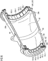
- FIG. 10 shows a front view on a section of a sectional cut through a bearing arrangement 70 of the wind turbine 10 of FIG. 1 , according to the invention, whereby the sectional cut is positioned before the upwind bearing 200.
- the bearing arrangements 70 of FIG. 7 and FIG. 8 there are no limit stops 220.1, 220.2 arranged adjacent to the radial bearing bodies 203.1, 203.2, 203.3, 203.4.
- the radial bearing bodies 203.1, 203.2, 203.3, 203.4 which are arranged adjacent to one another along a circumference of a cylindrical seat 202 of the bearing housing 80, are locked in movement relative to one another and relative to the cylindrical seat 202 by means of press-fitted locking pieces 221.1, 221.2, 221.3 in three directions according to the invention.
- the locking pieces 221.1, 221.2, 221.3 are provided as T-bar elements and protrude above the adjacent radial bearing bodies 203.1, 203.2, 203.3, 203.4 and intrude into the cylindrical seat 202, in particular into grooves having undercuts provided therein.
- the grooves are provided along the longitudinal axis A within the cylindrical seat 202, which is formed in the bearing housing 80 itself, in this particular embodiment.
- the undercuts extend in the tangential directions.
- the dovetail connections lock a movement of the bearing bodies 203.1, 203.2, 203.3 and thereby the thereto via the radial tiltable support structures 204.1, 204.2, 204.3, 204.4 attached radial bearing pads 205.1, 205.2, 205.3, 205.4 in the tangential directions.
- a locking in the radial direction is achieved by means of spring elements 222.1, 222.2, which are only denominated with respect to the locking piece 221.2 for reasons of clarity of the figure.
- the spring elements 221.1, 222.2 are provided as elastomers and are arranged between an upper part of the T shaped locking piece 221.2 and the radial bearing bodies 203.2, 203.3.
- Wear protection elements 223.1, 223.2, 223.3, 223.4 are arranged between the locking piece 221.2 and the bearing housing 80 and the radial bearing bodies 203.2, 203.3.
- the wear protection elements 223.1, 223.2 are arranged between the locking piece 221.2 and the radial bearing bodies 203.2, 203.3 and the wear protection elements 223.3, 223.4 are arranged between the locking piece 221.2 and the bearing housing 80, in particular at a location of the undercuts.
- the wear protection elements 223.1, 223.2, 223.3, 223.4 protect the locking piece 221.2 from wear.
- FIG. 11 shows a side perspective view on a sectional cut along the longitudinal axis A of the bearing arrangement 70 of FIG. 10 .
- a stop plate 224.2 is integrally formed with locking piece 221.2.
- the stop plate 224.2 has a larger extension in a radial direction than the locking piece 221.2.
- the stop plate 224.2 is pressed against a rim of the cylindrical seat 202.
- the rim as shown, may be a portion of the bearing housing 80 that is raised over the inner cylindrical surface of the bearing housing 80 and on which the cylindrical seat 202 may be provided for the radial fluid bearing.
- the stop plate 224.2 is bolted to the rim of the cylindrical seat 202.
- the stop plate 224.2 provides a locking in the axial direction along the longitudinal axis A.
Landscapes
- Engineering & Computer Science (AREA)
- General Engineering & Computer Science (AREA)
- Mechanical Engineering (AREA)
- Chemical & Material Sciences (AREA)
- Sustainable Energy (AREA)
- Life Sciences & Earth Sciences (AREA)
- Sustainable Development (AREA)
- Combustion & Propulsion (AREA)
- Physics & Mathematics (AREA)
- Fluid Mechanics (AREA)
- Oil, Petroleum & Natural Gas (AREA)
- Wind Motors (AREA)
- Support Of The Bearing (AREA)
- Power Engineering (AREA)
Claims (14)
- Agencement de palier (70) pour une éolienne (10) comprenant un logement de palier (80) et un arbre de transmission (90), grâce à quoi l'arbre de transmission (90) est agencé à l'intérieur du logement de palier (80) dans une direction axiale le long d'un axe longitudinal (A) du logement de palier (80), l'agencement de palier (70) comprenant en outre un palier sous le vent (100) et un palier face au vent (200), grâce à quoi le palier sous le vent (100) et le palier face au vent (200) sont agencés entre le logement de palier (80) et l'arbre de transmission (90), le palier sous le vent (100) et/ou le palier face au vent (200) étant un palier fluide radial comprenant une pluralité de coussinets de paliers radiaux (205), grâce à quoi chaque coussinet de la pluralité de coussinets de paliers radiaux (205) est fixé à un corps de palier radial d'une pluralité de corps de paliers radiaux (203) du palier fluide radial et la pluralité de coussinets de paliers radiaux (204) sont agencés autour de l'arbre de transmission (90), grâce à quoi la pluralité de corps de paliers (203) sont agencés adjacents les uns aux autres le long d'une circonférence d'une assise cylindrique (202) du logement de palier (80),
caractérisé en ce que
les corps de paliers adjacents (203) sont verrouillés en mouvement les uns par rapport aux autres et par rapport à l'assise cylindrique (202) au moyen de pièces de verrouillage à ajustement par pression (221), grâce à quoi les pièces de verrouillage (221) fournissent des connexions en queue d'aronde avec l'assise cylindrique (202). - Agencement de palier (70) selon la revendication 1, caractérisé en ce que
les pièces de verrouillage (221) font saillie au-dessus des corps de paliers adjacents (203). - Agencement de palier (70) selon la revendication 1 ou 2, caractérisé en ce que
les pièces de verrouillage (221) font intrusion dans l'assise cylindrique (202). - Agencement de palier (70) selon l'une quelconque des revendications précédentes,
caractérisé en ce que
des parties inférieures des pièces de verrouillage (221) s'étendent dans des directions tangentielles le long de la circonférence de l'assise cylindrique (202). - Agencement de palier (70) selon l'une quelconque des revendications précédentes,
caractérisé en ce que
au moins une des pièces de verrouillage (221) est un élément barre en T ou un élément barre en I. - Agencement de palier (70) selon la revendication 5, caractérisé en ce que
l'élément barre en T ou l'élément barre en I se compose d'un matériau rigide. - Agencement de palier (70) selon l'une quelconque des revendications précédentes,
caractérisé en ce que
au moins un élément ressort (222) est agencé entre la au moins une des pièces de verrouillage (221) et un des corps de paliers adjacents radiaux (203). - Agencement de palier (70) selon la revendication 7, caractérisé en ce que
un élément rigide est agencé entre le au moins un élément ressort (222) et le au moins un des corps de paliers adjacents (203). - Agencement de palier (70) selon l'une quelconque des revendications 7 à 8,
caractérisé en ce que
l'élément ressort (222) est un élastomère. - Agencement de palier (70) selon l'une quelconque des revendications précédentes,
caractérisé en ce que
la pièce de verrouillage (221) comprend une plaque de butée (224) agencée contre un rebord de l'assise cylindrique (202) dans une direction axiale le long de l'axe longitudinal (A). - Agencement de palier (70) selon l'une quelconque des revendications précédentes,
caractérisé en ce que
au moins un élément de protection contre l'usure (223) est agencé entre au moins une des pièces de verrouillage (221) et l'assise cylindrique (80) ou un corps de palier radial (203). - Agencement de palier (70) selon l'une quelconque des revendications précédentes,
caractérisé en ce que
chaque coussinet de la pluralité de coussinets de paliers radiaux (205) est fixé à un corps de palier radial de la pluralité de corps de paliers radiaux (203) au moyen d'une structure de support inclinable radiale (204), grâce à quoi en particulier la structure de support inclinable radiale (204) est raccordée à au moins un corps de palier radial de la pluralité de corps de paliers radiaux (203) au moyen d'une connexion à ressort (218). - Agencement de palier (70) selon l'une quelconque des revendications précédentes,
caractérisé en ce que
au moins une plaque d'interface incurvée (214) peut être fixée à au moins un corps de palier radial de la pluralité de corps de paliers radiaux (203) à l'opposé du coussinet de palier radial (205), grâce à quoi la plaque d'interface (214) est agencée en contact avec l'assise cylindrique (202) du palier fluide radial. - Éolienne (10) comprenant un agencement de palier (70) selon l'une quelconque des revendications précédentes, grâce à quoi l'éolienne (10) comprend en outre un rotor (50) raccordé de manière opérationnelle de façon à entraîner l'arbre de transmission (90) et un générateur (40) raccordé de manière opérationnelle de façon à être entraîné par l'arbre de transmission (90).
Priority Applications (4)
| Application Number | Priority Date | Filing Date | Title |
|---|---|---|---|
| EP19174858.1A EP3739224B1 (fr) | 2019-05-16 | 2019-05-16 | Agencement de palier d'une éolienne et éolienne |
| ES19174858T ES2933816T3 (es) | 2019-05-16 | 2019-05-16 | Disposición de cojinetes para una turbina eólica y turbina eólica |
| US16/870,029 US11293483B2 (en) | 2019-05-16 | 2020-05-08 | Bearing arrangement for a wind turbine and wind turbine |
| CN202010414205.XA CN111946734B (zh) | 2019-05-16 | 2020-05-15 | 用于风力涡轮机的轴承装置以及风力涡轮机 |
Applications Claiming Priority (1)
| Application Number | Priority Date | Filing Date | Title |
|---|---|---|---|
| EP19174858.1A EP3739224B1 (fr) | 2019-05-16 | 2019-05-16 | Agencement de palier d'une éolienne et éolienne |
Publications (2)
| Publication Number | Publication Date |
|---|---|
| EP3739224A1 EP3739224A1 (fr) | 2020-11-18 |
| EP3739224B1 true EP3739224B1 (fr) | 2022-10-26 |
Family
ID=66589306
Family Applications (1)
| Application Number | Title | Priority Date | Filing Date |
|---|---|---|---|
| EP19174858.1A Active EP3739224B1 (fr) | 2019-05-16 | 2019-05-16 | Agencement de palier d'une éolienne et éolienne |
Country Status (4)
| Country | Link |
|---|---|
| US (1) | US11293483B2 (fr) |
| EP (1) | EP3739224B1 (fr) |
| CN (1) | CN111946734B (fr) |
| ES (1) | ES2933816T3 (fr) |
Cited By (1)
| Publication number | Priority date | Publication date | Assignee | Title |
|---|---|---|---|---|
| WO2025201594A1 (fr) | 2024-03-26 | 2025-10-02 | Schaeffler Technologies AG & Co. KG | Ensemble palier coulissant |
Families Citing this family (2)
| Publication number | Priority date | Publication date | Assignee | Title |
|---|---|---|---|---|
| EP4043743B1 (fr) * | 2021-02-12 | 2023-10-04 | Siemens Gamesa Renewable Energy A/S | Palier d'éolienne, éolienne comprenant un palier et procédé de fabrication d'une bague de palier |
| CN117267253A (zh) * | 2023-10-20 | 2023-12-22 | 大唐新能源朔州风力发电有限公司 | 一种用于风电的径向轴承组件 |
Family Cites Families (16)
| Publication number | Priority date | Publication date | Assignee | Title |
|---|---|---|---|---|
| US2778696A (en) * | 1955-01-12 | 1957-01-22 | Ralph D Lease | Thrust bearing structure |
| GB1004733A (en) * | 1962-01-19 | 1965-09-15 | Glacier Co Ltd | Thrust bearing assemblies |
| CH569895A5 (fr) * | 1973-12-19 | 1975-11-28 | Maag Zahnraeder & Maschinen Ag | |
| CH668811A5 (de) * | 1984-07-19 | 1989-01-31 | Glyco Metall Werke | Hydrodynamisches gleitlager. |
| US7367713B2 (en) * | 2001-06-06 | 2008-05-06 | Delaware Capital Formation, Inc. | Journal bearing arrangement |
| CN201502632U (zh) | 2009-08-04 | 2010-06-09 | 申科滑动轴承股份有限公司 | 高压顶油轴承润滑油防逆流结构 |
| CN103953644A (zh) | 2014-05-21 | 2014-07-30 | 无锡杰尔压缩机有限公司 | 径向可调的可倾瓦轴承 |
| DK3219984T3 (en) | 2016-03-14 | 2019-04-08 | Siemens Ag | Sliding bearing assembly for a wind turbine |
| EP3252306B1 (fr) | 2016-05-31 | 2018-12-26 | Siemens Aktiengesellschaft | Éolienne comprenant un palier lisse |
| DK3276192T3 (da) | 2016-07-29 | 2020-02-24 | Siemens Gamesa Renewable Energy As | Lejeindretning |
| EP3279471B1 (fr) | 2016-08-03 | 2020-09-30 | Siemens Gamesa Renewable Energy A/S | Éolienne, boîtier de palier et procédé pour le fonctionnement d'une éolienne |
| CN110418902B (zh) | 2017-03-16 | 2021-10-15 | 西门子歌美飒可再生能源公司 | 滑动轴承垫支撑件 |
| DK3577361T3 (da) | 2017-03-16 | 2021-01-25 | Siemens Gamesa Renewable Energy As | Glidelejepudestøtte |
| EP3460269A1 (fr) | 2017-09-20 | 2019-03-27 | Siemens Gamesa Renewable Energy A/S | Palier à film de fluide pour éolienne |
| DK3460271T3 (da) | 2017-09-20 | 2020-08-31 | Siemens Gamesa Renewable Energy As | Fluidfilmleje til en vindmølle |
| DK3460238T3 (da) | 2017-09-20 | 2020-06-15 | Siemens Gamesa Renewable Energy As | Vindmølle |
-
2019
- 2019-05-16 ES ES19174858T patent/ES2933816T3/es active Active
- 2019-05-16 EP EP19174858.1A patent/EP3739224B1/fr active Active
-
2020
- 2020-05-08 US US16/870,029 patent/US11293483B2/en active Active
- 2020-05-15 CN CN202010414205.XA patent/CN111946734B/zh active Active
Cited By (2)
| Publication number | Priority date | Publication date | Assignee | Title |
|---|---|---|---|---|
| WO2025201594A1 (fr) | 2024-03-26 | 2025-10-02 | Schaeffler Technologies AG & Co. KG | Ensemble palier coulissant |
| DE102024108596A1 (de) * | 2024-03-26 | 2025-10-02 | Schaeffler Technologies AG & Co. KG | Gleitlageranordnung |
Also Published As
| Publication number | Publication date |
|---|---|
| CN111946734A (zh) | 2020-11-17 |
| ES2933816T3 (es) | 2023-02-14 |
| US20200362834A1 (en) | 2020-11-19 |
| US11293483B2 (en) | 2022-04-05 |
| CN111946734B (zh) | 2023-02-03 |
| EP3739224A1 (fr) | 2020-11-18 |
Similar Documents
| Publication | Publication Date | Title |
|---|---|---|
| EP3739224B1 (fr) | Agencement de palier d'une éolienne et éolienne | |
| KR101890436B1 (ko) | 기어 박스, 시일 및 커버 장치 | |
| US8827561B2 (en) | Main bearing for a wind turbine | |
| US20150016998A1 (en) | Wind turbine rotor | |
| EP2853733B1 (fr) | Ensemble de pale de rotor avec plaque de calage pour atténuer les charges de palier de pas | |
| EP3739226B1 (fr) | Agencement de palier d'une éolienne et éolienne | |
| EP3739205B1 (fr) | Agencement de palier d'une éolienne et éolienne | |
| US20230228253A1 (en) | Plain bearing arrangement and nacelle equipped with a plain bearing arrangement for a wind turbine, and wind turbine | |
| EP3739208B1 (fr) | Agencement de palier d'une éolienne et éolienne | |
| EP3739225B1 (fr) | Agencement de palier d'une éolienne et éolienne | |
| KR102881578B1 (ko) | 특히 풍력 터빈의 회전자 허브를 위한 유체 막 베어링 | |
| EP3739206B1 (fr) | Agencement de palier d'une éolienne et éolienne | |
| WO2012009482A2 (fr) | Mécanisme de raccordement à des fins de montage d'aubes pour une éolienne | |
| EP3739207A1 (fr) | Agencement de palier d'une éolienne et éolienne | |
| EP3771842B1 (fr) | Roulements de pale de rotor | |
| US9200619B2 (en) | Wind turbine yaw or pitch bearing utilizing a threaded bearing surface | |
| RU2179648C2 (ru) | Уплотнительное устройство за компрессором газотурбинного двигателя | |
| WO2014037432A1 (fr) | Système de freinage |
Legal Events
| Date | Code | Title | Description |
|---|---|---|---|
| PUAI | Public reference made under article 153(3) epc to a published international application that has entered the european phase |
Free format text: ORIGINAL CODE: 0009012 |
|
| STAA | Information on the status of an ep patent application or granted ep patent |
Free format text: STATUS: THE APPLICATION HAS BEEN PUBLISHED |
|
| AK | Designated contracting states |
Kind code of ref document: A1 Designated state(s): AL AT BE BG CH CY CZ DE DK EE ES FI FR GB GR HR HU IE IS IT LI LT LU LV MC MK MT NL NO PL PT RO RS SE SI SK SM TR |
|
| AX | Request for extension of the european patent |
Extension state: BA ME |
|
| STAA | Information on the status of an ep patent application or granted ep patent |
Free format text: STATUS: REQUEST FOR EXAMINATION WAS MADE |
|
| 17P | Request for examination filed |
Effective date: 20210419 |
|
| RBV | Designated contracting states (corrected) |
Designated state(s): AL AT BE BG CH CY CZ DE DK EE ES FI FR GB GR HR HU IE IS IT LI LT LU LV MC MK MT NL NO PL PT RO RS SE SI SK SM TR |
|
| GRAP | Despatch of communication of intention to grant a patent |
Free format text: ORIGINAL CODE: EPIDOSNIGR1 |
|
| STAA | Information on the status of an ep patent application or granted ep patent |
Free format text: STATUS: GRANT OF PATENT IS INTENDED |
|
| INTG | Intention to grant announced |
Effective date: 20220622 |
|
| GRAS | Grant fee paid |
Free format text: ORIGINAL CODE: EPIDOSNIGR3 |
|
| GRAA | (expected) grant |
Free format text: ORIGINAL CODE: 0009210 |
|
| STAA | Information on the status of an ep patent application or granted ep patent |
Free format text: STATUS: THE PATENT HAS BEEN GRANTED |
|
| AK | Designated contracting states |
Kind code of ref document: B1 Designated state(s): AL AT BE BG CH CY CZ DE DK EE ES FI FR GB GR HR HU IE IS IT LI LT LU LV MC MK MT NL NO PL PT RO RS SE SI SK SM TR |
|
| REG | Reference to a national code |
Ref country code: GB Ref legal event code: FG4D |
|
| REG | Reference to a national code |
Ref country code: CH Ref legal event code: EP |
|
| REG | Reference to a national code |
Ref country code: AT Ref legal event code: REF Ref document number: 1527217 Country of ref document: AT Kind code of ref document: T Effective date: 20221115 |
|
| REG | Reference to a national code |
Ref country code: DE Ref legal event code: R096 Ref document number: 602019020978 Country of ref document: DE |
|
| REG | Reference to a national code |
Ref country code: IE Ref legal event code: FG4D |
|
| REG | Reference to a national code |
Ref country code: LT Ref legal event code: MG9D |
|
| REG | Reference to a national code |
Ref country code: ES Ref legal event code: FG2A Ref document number: 2933816 Country of ref document: ES Kind code of ref document: T3 Effective date: 20230214 |
|
| REG | Reference to a national code |
Ref country code: NL Ref legal event code: MP Effective date: 20221026 |
|
| REG | Reference to a national code |
Ref country code: AT Ref legal event code: MK05 Ref document number: 1527217 Country of ref document: AT Kind code of ref document: T Effective date: 20221026 |
|
| PG25 | Lapsed in a contracting state [announced via postgrant information from national office to epo] |
Ref country code: NL Free format text: LAPSE BECAUSE OF FAILURE TO SUBMIT A TRANSLATION OF THE DESCRIPTION OR TO PAY THE FEE WITHIN THE PRESCRIBED TIME-LIMIT Effective date: 20221026 |
|
| PG25 | Lapsed in a contracting state [announced via postgrant information from national office to epo] |
Ref country code: SE Free format text: LAPSE BECAUSE OF FAILURE TO SUBMIT A TRANSLATION OF THE DESCRIPTION OR TO PAY THE FEE WITHIN THE PRESCRIBED TIME-LIMIT Effective date: 20221026 Ref country code: PT Free format text: LAPSE BECAUSE OF FAILURE TO SUBMIT A TRANSLATION OF THE DESCRIPTION OR TO PAY THE FEE WITHIN THE PRESCRIBED TIME-LIMIT Effective date: 20230227 Ref country code: NO Free format text: LAPSE BECAUSE OF FAILURE TO SUBMIT A TRANSLATION OF THE DESCRIPTION OR TO PAY THE FEE WITHIN THE PRESCRIBED TIME-LIMIT Effective date: 20230126 Ref country code: LT Free format text: LAPSE BECAUSE OF FAILURE TO SUBMIT A TRANSLATION OF THE DESCRIPTION OR TO PAY THE FEE WITHIN THE PRESCRIBED TIME-LIMIT Effective date: 20221026 Ref country code: FI Free format text: LAPSE BECAUSE OF FAILURE TO SUBMIT A TRANSLATION OF THE DESCRIPTION OR TO PAY THE FEE WITHIN THE PRESCRIBED TIME-LIMIT Effective date: 20221026 Ref country code: AT Free format text: LAPSE BECAUSE OF FAILURE TO SUBMIT A TRANSLATION OF THE DESCRIPTION OR TO PAY THE FEE WITHIN THE PRESCRIBED TIME-LIMIT Effective date: 20221026 |
|
| PG25 | Lapsed in a contracting state [announced via postgrant information from national office to epo] |
Ref country code: RS Free format text: LAPSE BECAUSE OF FAILURE TO SUBMIT A TRANSLATION OF THE DESCRIPTION OR TO PAY THE FEE WITHIN THE PRESCRIBED TIME-LIMIT Effective date: 20221026 Ref country code: PL Free format text: LAPSE BECAUSE OF FAILURE TO SUBMIT A TRANSLATION OF THE DESCRIPTION OR TO PAY THE FEE WITHIN THE PRESCRIBED TIME-LIMIT Effective date: 20221026 Ref country code: LV Free format text: LAPSE BECAUSE OF FAILURE TO SUBMIT A TRANSLATION OF THE DESCRIPTION OR TO PAY THE FEE WITHIN THE PRESCRIBED TIME-LIMIT Effective date: 20221026 Ref country code: IS Free format text: LAPSE BECAUSE OF FAILURE TO SUBMIT A TRANSLATION OF THE DESCRIPTION OR TO PAY THE FEE WITHIN THE PRESCRIBED TIME-LIMIT Effective date: 20230226 Ref country code: HR Free format text: LAPSE BECAUSE OF FAILURE TO SUBMIT A TRANSLATION OF THE DESCRIPTION OR TO PAY THE FEE WITHIN THE PRESCRIBED TIME-LIMIT Effective date: 20221026 Ref country code: GR Free format text: LAPSE BECAUSE OF FAILURE TO SUBMIT A TRANSLATION OF THE DESCRIPTION OR TO PAY THE FEE WITHIN THE PRESCRIBED TIME-LIMIT Effective date: 20230127 |
|
| REG | Reference to a national code |
Ref country code: DE Ref legal event code: R097 Ref document number: 602019020978 Country of ref document: DE |
|
| PG25 | Lapsed in a contracting state [announced via postgrant information from national office to epo] |
Ref country code: SM Free format text: LAPSE BECAUSE OF FAILURE TO SUBMIT A TRANSLATION OF THE DESCRIPTION OR TO PAY THE FEE WITHIN THE PRESCRIBED TIME-LIMIT Effective date: 20221026 Ref country code: RO Free format text: LAPSE BECAUSE OF FAILURE TO SUBMIT A TRANSLATION OF THE DESCRIPTION OR TO PAY THE FEE WITHIN THE PRESCRIBED TIME-LIMIT Effective date: 20221026 Ref country code: EE Free format text: LAPSE BECAUSE OF FAILURE TO SUBMIT A TRANSLATION OF THE DESCRIPTION OR TO PAY THE FEE WITHIN THE PRESCRIBED TIME-LIMIT Effective date: 20221026 Ref country code: DK Free format text: LAPSE BECAUSE OF FAILURE TO SUBMIT A TRANSLATION OF THE DESCRIPTION OR TO PAY THE FEE WITHIN THE PRESCRIBED TIME-LIMIT Effective date: 20221026 Ref country code: CZ Free format text: LAPSE BECAUSE OF FAILURE TO SUBMIT A TRANSLATION OF THE DESCRIPTION OR TO PAY THE FEE WITHIN THE PRESCRIBED TIME-LIMIT Effective date: 20221026 |
|
| PG25 | Lapsed in a contracting state [announced via postgrant information from national office to epo] |
Ref country code: SK Free format text: LAPSE BECAUSE OF FAILURE TO SUBMIT A TRANSLATION OF THE DESCRIPTION OR TO PAY THE FEE WITHIN THE PRESCRIBED TIME-LIMIT Effective date: 20221026 Ref country code: AL Free format text: LAPSE BECAUSE OF FAILURE TO SUBMIT A TRANSLATION OF THE DESCRIPTION OR TO PAY THE FEE WITHIN THE PRESCRIBED TIME-LIMIT Effective date: 20221026 |
|
| PLBE | No opposition filed within time limit |
Free format text: ORIGINAL CODE: 0009261 |
|
| STAA | Information on the status of an ep patent application or granted ep patent |
Free format text: STATUS: NO OPPOSITION FILED WITHIN TIME LIMIT |
|
| 26N | No opposition filed |
Effective date: 20230727 |
|
| PG25 | Lapsed in a contracting state [announced via postgrant information from national office to epo] |
Ref country code: SI Free format text: LAPSE BECAUSE OF FAILURE TO SUBMIT A TRANSLATION OF THE DESCRIPTION OR TO PAY THE FEE WITHIN THE PRESCRIBED TIME-LIMIT Effective date: 20221026 |
|
| REG | Reference to a national code |
Ref country code: CH Ref legal event code: PL |
|
| PG25 | Lapsed in a contracting state [announced via postgrant information from national office to epo] |
Ref country code: MC Free format text: LAPSE BECAUSE OF FAILURE TO SUBMIT A TRANSLATION OF THE DESCRIPTION OR TO PAY THE FEE WITHIN THE PRESCRIBED TIME-LIMIT Effective date: 20221026 |
|
| REG | Reference to a national code |
Ref country code: BE Ref legal event code: MM Effective date: 20230531 |
|
| PG25 | Lapsed in a contracting state [announced via postgrant information from national office to epo] |
Ref country code: MC Free format text: LAPSE BECAUSE OF FAILURE TO SUBMIT A TRANSLATION OF THE DESCRIPTION OR TO PAY THE FEE WITHIN THE PRESCRIBED TIME-LIMIT Effective date: 20221026 Ref country code: LU Free format text: LAPSE BECAUSE OF NON-PAYMENT OF DUE FEES Effective date: 20230516 Ref country code: LI Free format text: LAPSE BECAUSE OF NON-PAYMENT OF DUE FEES Effective date: 20230531 Ref country code: CH Free format text: LAPSE BECAUSE OF NON-PAYMENT OF DUE FEES Effective date: 20230531 |
|
| REG | Reference to a national code |
Ref country code: IE Ref legal event code: MM4A |
|
| PG25 | Lapsed in a contracting state [announced via postgrant information from national office to epo] |
Ref country code: IE Free format text: LAPSE BECAUSE OF NON-PAYMENT OF DUE FEES Effective date: 20230516 |
|
| PG25 | Lapsed in a contracting state [announced via postgrant information from national office to epo] |
Ref country code: IE Free format text: LAPSE BECAUSE OF NON-PAYMENT OF DUE FEES Effective date: 20230516 |
|
| PG25 | Lapsed in a contracting state [announced via postgrant information from national office to epo] |
Ref country code: IT Free format text: LAPSE BECAUSE OF FAILURE TO SUBMIT A TRANSLATION OF THE DESCRIPTION OR TO PAY THE FEE WITHIN THE PRESCRIBED TIME-LIMIT Effective date: 20221026 Ref country code: BE Free format text: LAPSE BECAUSE OF NON-PAYMENT OF DUE FEES Effective date: 20230531 |
|
| PG25 | Lapsed in a contracting state [announced via postgrant information from national office to epo] |
Ref country code: BG Free format text: LAPSE BECAUSE OF FAILURE TO SUBMIT A TRANSLATION OF THE DESCRIPTION OR TO PAY THE FEE WITHIN THE PRESCRIBED TIME-LIMIT Effective date: 20221026 |
|
| PG25 | Lapsed in a contracting state [announced via postgrant information from national office to epo] |
Ref country code: BG Free format text: LAPSE BECAUSE OF FAILURE TO SUBMIT A TRANSLATION OF THE DESCRIPTION OR TO PAY THE FEE WITHIN THE PRESCRIBED TIME-LIMIT Effective date: 20221026 |
|
| PGFP | Annual fee paid to national office [announced via postgrant information from national office to epo] |
Ref country code: DE Payment date: 20250528 Year of fee payment: 7 |
|
| PGFP | Annual fee paid to national office [announced via postgrant information from national office to epo] |
Ref country code: ES Payment date: 20250611 Year of fee payment: 7 |
|
| PGFP | Annual fee paid to national office [announced via postgrant information from national office to epo] |
Ref country code: FR Payment date: 20250526 Year of fee payment: 7 |
|
| PG25 | Lapsed in a contracting state [announced via postgrant information from national office to epo] |
Ref country code: CY Free format text: LAPSE BECAUSE OF FAILURE TO SUBMIT A TRANSLATION OF THE DESCRIPTION OR TO PAY THE FEE WITHIN THE PRESCRIBED TIME-LIMIT; INVALID AB INITIO Effective date: 20190516 |
|
| PG25 | Lapsed in a contracting state [announced via postgrant information from national office to epo] |
Ref country code: HU Free format text: LAPSE BECAUSE OF FAILURE TO SUBMIT A TRANSLATION OF THE DESCRIPTION OR TO PAY THE FEE WITHIN THE PRESCRIBED TIME-LIMIT; INVALID AB INITIO Effective date: 20190516 |
|
| PG25 | Lapsed in a contracting state [announced via postgrant information from national office to epo] |
Ref country code: TR Free format text: LAPSE BECAUSE OF FAILURE TO SUBMIT A TRANSLATION OF THE DESCRIPTION OR TO PAY THE FEE WITHIN THE PRESCRIBED TIME-LIMIT Effective date: 20221026 |
|
| PGFP | Annual fee paid to national office [announced via postgrant information from national office to epo] |
Ref country code: GB Payment date: 20260323 Year of fee payment: 8 |