EP3739238A1 - Transmission de puissance pour les machines agricoles - Google Patents
Transmission de puissance pour les machines agricoles Download PDFInfo
- Publication number
- EP3739238A1 EP3739238A1 EP20174037.0A EP20174037A EP3739238A1 EP 3739238 A1 EP3739238 A1 EP 3739238A1 EP 20174037 A EP20174037 A EP 20174037A EP 3739238 A1 EP3739238 A1 EP 3739238A1
- Authority
- EP
- European Patent Office
- Prior art keywords
- shaft
- gear
- group
- unit
- powershift transmission
- Prior art date
- Legal status (The legal status is an assumption and is not a legal conclusion. Google has not performed a legal analysis and makes no representation as to the accuracy of the status listed.)
- Withdrawn
Links
- 230000005540 biological transmission Effects 0.000 title claims abstract description 55
- 238000011144 upstream manufacturing Methods 0.000 claims abstract description 20
- 230000009467 reduction Effects 0.000 description 8
- 230000008878 coupling Effects 0.000 description 6
- 238000010168 coupling process Methods 0.000 description 6
- 238000005859 coupling reaction Methods 0.000 description 6
- 238000000034 method Methods 0.000 description 3
- 230000008569 process Effects 0.000 description 2
- 241000295146 Gallionellaceae Species 0.000 description 1
- 230000008901 benefit Effects 0.000 description 1
- 230000008859 change Effects 0.000 description 1
- 238000002485 combustion reaction Methods 0.000 description 1
- 230000001419 dependent effect Effects 0.000 description 1
- 238000010586 diagram Methods 0.000 description 1
- 239000000446 fuel Substances 0.000 description 1
- 238000009434 installation Methods 0.000 description 1
- 238000004519 manufacturing process Methods 0.000 description 1
- 230000002093 peripheral effect Effects 0.000 description 1
- 230000001141 propulsive effect Effects 0.000 description 1
- 239000002689 soil Substances 0.000 description 1
Images


Classifications
-
- F—MECHANICAL ENGINEERING; LIGHTING; HEATING; WEAPONS; BLASTING
- F16—ENGINEERING ELEMENTS AND UNITS; GENERAL MEASURES FOR PRODUCING AND MAINTAINING EFFECTIVE FUNCTIONING OF MACHINES OR INSTALLATIONS; THERMAL INSULATION IN GENERAL
- F16H—GEARING
- F16H37/00—Combinations of mechanical gearings, not provided for in groups F16H1/00 - F16H35/00
- F16H37/02—Combinations of mechanical gearings, not provided for in groups F16H1/00 - F16H35/00 comprising essentially only toothed or friction gearings
- F16H37/04—Combinations of toothed gearings only
- F16H37/042—Combinations of toothed gearings only change gear transmissions in group arrangement
- F16H37/046—Combinations of toothed gearings only change gear transmissions in group arrangement with an additional planetary gear train, e.g. creep gear, overdrive
-
- F—MECHANICAL ENGINEERING; LIGHTING; HEATING; WEAPONS; BLASTING
- F16—ENGINEERING ELEMENTS AND UNITS; GENERAL MEASURES FOR PRODUCING AND MAINTAINING EFFECTIVE FUNCTIONING OF MACHINES OR INSTALLATIONS; THERMAL INSULATION IN GENERAL
- F16H—GEARING
- F16H3/00—Toothed gearings for conveying rotary motion with variable gear ratio or for reversing rotary motion
- F16H3/006—Toothed gearings for conveying rotary motion with variable gear ratio or for reversing rotary motion power being selectively transmitted by parallel flow paths, e.g. dual clutch transmissions
-
- F—MECHANICAL ENGINEERING; LIGHTING; HEATING; WEAPONS; BLASTING
- F16—ENGINEERING ELEMENTS AND UNITS; GENERAL MEASURES FOR PRODUCING AND MAINTAINING EFFECTIVE FUNCTIONING OF MACHINES OR INSTALLATIONS; THERMAL INSULATION IN GENERAL
- F16H—GEARING
- F16H3/00—Toothed gearings for conveying rotary motion with variable gear ratio or for reversing rotary motion
- F16H3/02—Toothed gearings for conveying rotary motion with variable gear ratio or for reversing rotary motion without gears having orbital motion
- F16H3/08—Toothed gearings for conveying rotary motion with variable gear ratio or for reversing rotary motion without gears having orbital motion exclusively or essentially with continuously meshing gears, that can be disengaged from their shafts
- F16H3/087—Toothed gearings for conveying rotary motion with variable gear ratio or for reversing rotary motion without gears having orbital motion exclusively or essentially with continuously meshing gears, that can be disengaged from their shafts characterised by the disposition of the gears
- F16H3/091—Toothed gearings for conveying rotary motion with variable gear ratio or for reversing rotary motion without gears having orbital motion exclusively or essentially with continuously meshing gears, that can be disengaged from their shafts characterised by the disposition of the gears including a single countershaft
-
- F—MECHANICAL ENGINEERING; LIGHTING; HEATING; WEAPONS; BLASTING
- F16—ENGINEERING ELEMENTS AND UNITS; GENERAL MEASURES FOR PRODUCING AND MAINTAINING EFFECTIVE FUNCTIONING OF MACHINES OR INSTALLATIONS; THERMAL INSULATION IN GENERAL
- F16H—GEARING
- F16H37/00—Combinations of mechanical gearings, not provided for in groups F16H1/00 - F16H35/00
- F16H37/02—Combinations of mechanical gearings, not provided for in groups F16H1/00 - F16H35/00 comprising essentially only toothed or friction gearings
- F16H37/04—Combinations of toothed gearings only
- F16H37/042—Combinations of toothed gearings only change gear transmissions in group arrangement
-
- F—MECHANICAL ENGINEERING; LIGHTING; HEATING; WEAPONS; BLASTING
- F16—ENGINEERING ELEMENTS AND UNITS; GENERAL MEASURES FOR PRODUCING AND MAINTAINING EFFECTIVE FUNCTIONING OF MACHINES OR INSTALLATIONS; THERMAL INSULATION IN GENERAL
- F16H—GEARING
- F16H57/00—General details of gearing
- F16H57/02—Gearboxes; Mounting gearing therein
- F16H57/033—Series gearboxes, e.g. gearboxes based on the same design being available in different sizes or gearboxes using a combination of several standardised units
-
- B—PERFORMING OPERATIONS; TRANSPORTING
- B60—VEHICLES IN GENERAL
- B60Y—INDEXING SCHEME RELATING TO ASPECTS CROSS-CUTTING VEHICLE TECHNOLOGY
- B60Y2200/00—Type of vehicle
- B60Y2200/20—Off-Road Vehicles
- B60Y2200/22—Agricultural vehicles
- B60Y2200/221—Tractors
-
- F—MECHANICAL ENGINEERING; LIGHTING; HEATING; WEAPONS; BLASTING
- F16—ENGINEERING ELEMENTS AND UNITS; GENERAL MEASURES FOR PRODUCING AND MAINTAINING EFFECTIVE FUNCTIONING OF MACHINES OR INSTALLATIONS; THERMAL INSULATION IN GENERAL
- F16H—GEARING
- F16H3/00—Toothed gearings for conveying rotary motion with variable gear ratio or for reversing rotary motion
- F16H3/02—Toothed gearings for conveying rotary motion with variable gear ratio or for reversing rotary motion without gears having orbital motion
- F16H3/08—Toothed gearings for conveying rotary motion with variable gear ratio or for reversing rotary motion without gears having orbital motion exclusively or essentially with continuously meshing gears, that can be disengaged from their shafts
- F16H2003/0818—Toothed gearings for conveying rotary motion with variable gear ratio or for reversing rotary motion without gears having orbital motion exclusively or essentially with continuously meshing gears, that can be disengaged from their shafts comprising means for power-shifting
Definitions
- the present invention relates to a power shift transmission for agricultural machinery.
- Powershift transmissions are a special form of vehicle transmissions in which a ratio can be changed under load, i.e. while driving, without interrupting the torque. As a result, propulsive forces can also be transmitted during the shift process, so that the vehicle can continue to accelerate during the shift process. This means that there is no loss of comfort when switching.
- Power shift transmissions are predominantly used in agricultural utility vehicles, especially tractors, because they enable faster work and help save fuel, especially when working in hilly terrain and on changing types of soil.
- Some tractor transmissions can only be partially shifted, which means that it is only possible to shift between some gears without interruption of the tractive effort, while others (e.g. group change) involve an interruption of tractive effort.
- transmissions are characterized in that, in a first circuit, a clutch connected to an input shaft connects the input shaft to the output shaft, so that the transmission can be operated in through-drive mode, with the planetary gear running free.
- the clutch is released, so that the planet carrier is driven by the input shaft and the planetary gear set rolls around a first sun gear, which is locked by a brake and through which the output shaft extends.
- the output takes place via a second sun gear connected to the output shaft, which is driven by the planetary gear set.
- the powershift transmission can be operated in reduction mode or in reversing mode.
- a two-stage powershift transmission is provided, which, however, on the one hand is complex in terms of production engineering, and on the other hand does not allow a further operating mode, for example a creep mode, in the arrangement mentioned.
- the powershift transmission has a planetary gear set.
- the planetary gear includes a planet carrier which is connected to the input shaft.
- the first output shaft can be connected to the output-side sun of a stepped planetary set with a switching element.
- the first output shaft can be connected directly to the input shaft with a second switching element.
- the input-side sun gear of the stepped planetary set is non-rotatably connected to a housing part of the powershift transmission.
- the invention is based on the object of specifying a powershift transmission that, on the one hand, can be implemented with a large number of gear variants while at the same time being compact in size and, on the other hand, can be used for a wide range of applications.
- the powershift transmission has a transmission housing, an input shaft unit and an output shaft, the input shaft unit and the output shaft extending at least in sections within the housing, a secondary shaft being arranged offset in parallel between the input shaft unit and the output shaft within the housing, the input shaft unit and the
- the auxiliary shaft is connected to one another via a series group and the auxiliary shaft and the output shaft are connected to one another via a series group, each switching group being connected or disconnected Having decoupling gear pairs
- the input shaft unit has an outer shaft and an inner shaft arranged coaxially on the outer shaft and rotatable relative to the outer shaft, and the inner shaft and the outer shaft are connected to one another via a countershaft.
- the powershift transmission can be connected to a drive machine, e.g. B. be connected to an internal combustion engine so that the torque fed in can be transmitted to the output shaft via the powershift transmission.
- a drive machine e.g. B. be connected to an internal combustion engine so that the torque fed in can be transmitted to the output shaft via the powershift transmission.
- a machine or a drive shaft for. B. be connected for wheels.
- the powershift transmission has two shift groups and a back gear.
- a countershaft is an extension of the gearbox, which generally has at least two switching states, one switching state being provided for a low load state and another switching state for a high load state.
- the switching states of the additional gear are usually designated as "Hi” for the high load state and "Lo" for the low load state.
- the invention is based on the knowledge that a more compact design can be achieved if the input shaft is designed in the form of an input shaft unit with two coaxially arranged shafts in the form of an inner shaft and an outer shaft, in which case the countershaft connects the inner shaft with the outer shaft.
- torque is transmitted between the inner and outer shafts, which means that different peripheral speeds can develop between the inner and outer shafts.
- the back gear has at least one planetary gear stage with at least one sun gear, a ring gear, and a planetary group consisting of at least one first and at least one second planetary gear.
- the first planetary gear is arranged between the sun gear and the second planetary gear and the second planetary gear is arranged between the first planetary gear and the ring gear.
- the sun gear is connected to the ring gear via the first planet gear and the second planet gear.
- not only one planet gear is provided along the circumference of a planet group. Rather, the ring gear is supported on the sun gear via at least three planet gears arranged along the circumference. With such a design, there would then be both three first planet gears and three second planet gears.
- the invention is not limited to such a design.
- the sun gear is coupled directly to the inner shaft of the input shaft unit.
- the planetary group is preferably coupled to the outer shaft of the input shaft unit.
- What is special about a planetary gear stage is that, starting from a sun gear, a planetary group and a ring gear, two of these components can be operated independently of one another.
- the ring gear is not fixed both in the first and in the second switching state and is accordingly rotatable based on the movement of the sun gear and the planetary group.
- the type and manner of rotation results from the rotation of the sun gear and the rotation of the planetary group.
- the planetary group is coupled directly to the inner shaft in a first switching state.
- both the sun gear and the planetary group have the same rotational speed, so that accordingly no relative movement is formed between the planetary group and the sun gear.
- the outer shaft is preferably also coupled directly to the planetary group, the speed of rotation of the inner shaft is directly applied to the outer shaft transfer.
- the planetary group of the planetary gear stage is coupled to the inner shaft of the input shaft unit via at least one counter gear pair.
- This counter gear pair can bring about either a step-up or a step-down, so that the planetary group accordingly has either a lower or a higher speed of rotation than the sun wheel. Consequently, a relative speed develops between the sun gear and the planetary group, but the direction of rotation of the sun gear and the planetary group is the same.
- the individual switching states are implemented via a clutch each, with multi-plate clutches preferably being used.
- At least one additional shaft is provided in order to bring about a reduction or translation by the counter gear pair in the second switching state, the drive gear of the at least one counter gear pair being arranged on the inner shaft and the driven gear being arranged on the additional shaft.
- there is preferably a double reduction or translation with a second drive gear being arranged on the additional shaft and a corresponding second output gear being arranged on an outer shaft section of the countershaft, the outer shaft section being arranged coaxially to the inner shaft and correspondingly connected to the planetary group via a coupling .
- the direction of rotation of the output shaft can also be reversed in a simple manner via the planetary gear stage. This is done by reversing the direction of rotation of the outer shaft.
- the ring gear is fixed against rotation, while the sun gear continues to be driven directly via the inner shaft.
- the planetary group is decoupled from the inner shaft.
- the planetary group rotates in the opposite direction to the sun gear. The direction of rotation of the outer shaft is thus opposite to that of the first and second switching states.
- the inner shaft can also be coupled to the outer shaft via a classically designed countershaft with two countershaft gear pairs.
- the countershaft has at least a first and a second countershaft pair, wherein in a first switching state the inner shaft of the input unit is in connection directly and / or in a second switching state via the first and second countershaft pair with the outer shaft of the input unit.
- the main difference compared to the first embodiment, however, is that the direction of rotation of the outer shaft cannot be reversed in a simple manner by fixing a ring gear of the planetary gear stage.
- the powershift transmission can also have a stage in which the range group is bypassed.
- bridged does not mean that the auxiliary shaft is ignored in this switching state.
- the secondary shaft serves as a carrier for an intermediate gear.
- the drive gear of the input shaft unit like the other drive gears of the upstream group, is arranged on the outer shaft and the output gear is arranged on the output shaft.
- the intermediate gear is then arranged on the auxiliary shaft between the drive gear and the output gear, so that torque is transmitted from the drive gear via the intermediate gear to the output gear.
- the special feature is that the torque is transmitted directly via the intermediate gear.
- the additional coupling of a gear of the downstream group is therefore not necessary in order to bring about a rotation of the output shaft.
- the design of the input shaft unit with an inner shaft and an outer shaft makes it possible to achieve a particularly compact design of the powershift transmission.
- Such a design is not limited to the input shaft unit only.
- the auxiliary shaft and the output shaft can also be designed as a auxiliary shaft unit and output shaft unit and accordingly each have an inner shaft and an outer shaft mounted coaxially and rotatably therewith.
- Such a design has the advantage that different speeds of rotation between the inner shaft and the outer shaft can also be generated for the auxiliary shaft unit and the output shaft unit, with different switching states of the upstream and downstream groups then being realized that a distinction is made as to whether the corresponding outer shaft or inner shaft is driven by the corresponding output gear.
- the gear wheel pairs of the upstream and downstream groups are preferably each coupled or uncoupled via a separate associated clutch, the clutches preferably being multi-disk clutches.
- the powershift transmission is designed in its core function to transmit torque from the input shaft unit to the output shaft, both on the input shaft and on the output shaft or on additional shafts, work machines such. B. pumps, can be connected so that a variety of different machines can be operated at different speeds and load conditions.
- FIG 1 shows an agricultural machine in the form of a tractor 10 and any device 12 pulled by the tractor, which in the exemplary embodiment is designed purely as a round baler.
- the device 12 comprises a chassis 14 supported on wheels 16 with a baling chamber 18.
- the device 12 is pulled from the tractor 10 via a drawbar 20.
- Their drivable elements are driven by the tractor 10 by means of a power take-off shaft 22.
- the tractor 10 comprises a chassis 24 which is supported on front, steerable wheels 26 and rear-driven wheels 28.
- An operator's workstation with a seat 32 is located in a cabin 30.
- a steering wheel 34, an accelerator pedal 36 and an operator station 38 can be operated from the seat.
- the Figure 2 shows a schematic diagram of the powershift transmission according to the invention.
- the powershift transmission has an input shaft unit 41 consisting of an outer shaft 42 and an inner shaft 43 which is arranged coaxially in the outer shaft 42 and is justifiable with respect to the outer shaft 42.
- the powershift transmission has an output shaft 61 and an auxiliary shaft 51 offset parallel to the input shaft unit 41 and to the output shaft 61.
- the inner shaft 43 of the input shaft unit 41 is directly coupled to a drive machine 49, the torque transmission from the drive machine 49 to the output shaft 61 taking place via a countershaft 40, an upstream group 50 and a downstream group 60.
- the back gear 40 is provided between the inner shaft 43 and the outer shaft 42, with the back gear 40 being able to implement different transmission or reduction ratios between the inner shaft 43 and the outer shaft 42. This has the consequence that, in principle, different rotational speeds can develop between the inner shaft 43 and the outer shaft 42.
- the countershaft 40 has a planetary gear stage 44.
- This planetary gear stage 44 is composed of a central sun gear 44d, a first planet gear 44c, a second planet gear 44b and a ring gear 44a.
- the sun gear 44d is directly connected to the inner shaft 43.
- the outer shaft 43 is connected to the first and second planet gears 44b, 44c, which form a common so-called planetary group.
- the countershaft 40 has two switching states that can be switched by actuating the clutches Lo and Hi.
- the clutch Lo operates a low load condition and the clutch Hi a high load condition.
- the main difference between these two switching states results from the following consideration.
- An actuation of the clutch Hi has the consequence that the planetary group is coupled directly to the inner shaft 43. Consequently, both the inner shaft 43, the sun gear 44d and also the planetary group consisting of the planetary gears 44b, 44c have the same rotational speed. There is therefore no relative speed between the sun gear 44d and the planetary group.
- a reversing unit, which can be actuated via the clutch 47, is also implemented via the countershaft 40.
- the actuation of this clutch 47 results in the ring gear 44a being fixed against rotation.
- the inner shaft 43 continues to be driven in a first direction of rotation via the drive machine 49. Since the clutches Lo and Hi are not actuated in this state, the rotation of the planetary group is solely dependent on the rotation of the sun gear 44d and the ring gear 47. To compensate for the rotation of the sun gear 44d with respect to a stationary ring gear 44a To be able to, the planetary group completes a rotation opposite to the sun gear 44d. However, since the planetary group is still connected to the outer shaft 42, the rotation of the outer shaft 42 is reversed.
- the powershift transmission also has an upstream group 50 via which the torque is transmitted from the outer shaft 42 of the input shaft unit 41 to the auxiliary shaft 51.
- the upstream group 50 has a total of four gear wheel pairs I, II, III, IV, each of which is assembled via a drive gear on the outer shaft 42 and a driven gear on the auxiliary shaft 51.
- a downstream group 60 is in turn arranged, which has a total of two pairs of gearwheels A, B.
- the output shaft 61 is also formed as an output shaft unit consisting of an output inner shaft 63 and an output outer shaft 62, the output outer shaft 62 in turn being divided into two sections 62a, 62b.
- the output gears of the downstream group 60 are arranged either on the output inner shaft 63 or on the section 62b of the output outer shaft 62.
- downstream group 60 can also be bridged so that the torque is transmitted directly from a drive gear of the upstream group 52 to an output gear of the upstream group 54, the output gear 54 being arranged on the section 62a of the output outer shaft 62.
- the output gear 53 of the upstream group 50 which is actually seated on the auxiliary shaft 51, is designed as an intermediate gear via which the torque is transmitted from the drive gear 52 to the output gear 54.
- the Figure 3 shows an alternative embodiment in this regard, in which the rear-mounted group 60 is implemented via only one gear pair B, the switching states of the rear-mounted group 60 taking place via different couplings of the auxiliary shaft 51.
- the auxiliary shaft 51 thus has two auxiliary shaft sections 51a, 51b which are separate from one another and which can be coupled to one another and can be coupled in from the upstream group 41 in different step-up or step-down ratios.
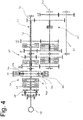
- the Figure 4 essentially corresponds to the switching principle of Figure 3 , whereby the clutch for the downstream group 60 is not in the form of a multi-plate clutch, as is the case with the embodiments of Figure 2 and Figure 3 was the case, but is implemented in the form of a cone clutch.
- FIG. 5 essentially corresponds to the switching principle of Figures 2 to 4 , although the intermediate gear 40 now has no planetary gear stage 44. Rather, the inner shaft 43 is coupled to the outer shaft 42 either directly via the clutch Hi or indirectly via the counter gear pairs 45, provided that the clutch Lo is actuated. The reversal of the direction of rotation of the outer shaft 42 is implemented via the coupling 47 and a total of three gears 46 connected in series.
Landscapes
- Engineering & Computer Science (AREA)
- General Engineering & Computer Science (AREA)
- Mechanical Engineering (AREA)
- Structure Of Transmissions (AREA)
Applications Claiming Priority (1)
| Application Number | Priority Date | Filing Date | Title |
|---|---|---|---|
| DE102019206979.7A DE102019206979A1 (de) | 2019-05-14 | 2019-05-14 | Lastschaltgetriebe für Landmaschinen |
Publications (1)
| Publication Number | Publication Date |
|---|---|
| EP3739238A1 true EP3739238A1 (fr) | 2020-11-18 |
Family
ID=70681733
Family Applications (1)
| Application Number | Title | Priority Date | Filing Date |
|---|---|---|---|
| EP20174037.0A Withdrawn EP3739238A1 (fr) | 2019-05-14 | 2020-05-12 | Transmission de puissance pour les machines agricoles |
Country Status (3)
| Country | Link |
|---|---|
| US (1) | US11391353B2 (fr) |
| EP (1) | EP3739238A1 (fr) |
| DE (1) | DE102019206979A1 (fr) |
Families Citing this family (2)
| Publication number | Priority date | Publication date | Assignee | Title |
|---|---|---|---|---|
| DE102020121209A1 (de) | 2020-08-12 | 2022-02-17 | Deere & Company | Lastschaltgetriebe und Fahrzeug |
| US12044296B2 (en) | 2021-12-20 | 2024-07-23 | Deere & Company | Power shift transmission |
Citations (9)
| Publication number | Priority date | Publication date | Assignee | Title |
|---|---|---|---|---|
| EP0745198B1 (fr) | 1994-02-16 | 1998-08-12 | Detlef Tolksdorf | Boite de vitesse, notamment pour machines de chantier et de travail mobiles, et procede de commande de boites de vitesse |
| EP2158417A2 (fr) * | 2007-05-19 | 2010-03-03 | Valtra Inc | Transmissions |
| WO2013064371A1 (fr) | 2011-10-31 | 2013-05-10 | Deere & Company | Boîte de vitesses avec commande sous charge |
| WO2013099840A1 (fr) * | 2011-12-26 | 2013-07-04 | 本田技研工業株式会社 | Transmission |
| CN103459894A (zh) * | 2011-10-18 | 2013-12-18 | Dti集团有限公司 | 变速器系统及改变传动比的方法 |
| DE102013110709A1 (de) * | 2013-09-27 | 2015-04-02 | CLAAS Tractor S.A.S | Schaltgetriebeanordnung |
| DE102015215726A1 (de) * | 2015-08-18 | 2017-02-23 | Deere & Company | Gruppenschaltgetriebe und Getriebeanordnung mit einem Gruppenschaltgetriebe |
| EP3428480A2 (fr) * | 2017-06-22 | 2019-01-16 | Kubota Corporation | Transmission de véhicule de travail et véhicule de travail en étant équipé |
| EP3446556A1 (fr) * | 2016-04-01 | 2019-02-27 | LS Mtron Ltd. | Appareil de transmission d'automobile de travail agricole |
Family Cites Families (21)
| Publication number | Priority date | Publication date | Assignee | Title |
|---|---|---|---|---|
| US4074592A (en) * | 1976-04-29 | 1978-02-21 | Caterpillar Tractor Co. | Direct drive transmission with hydraulically actuated forward and reverse clutches |
| US4074581A (en) * | 1976-05-11 | 1978-02-21 | Caterpillar Tractor Co. | Compact transmission having a power takeoff shaft and hydraulically actuated clutches |
| JP4968494B2 (ja) | 2001-03-05 | 2012-07-04 | アイシン・エィ・ダブリュ株式会社 | 車両用変速機 |
| DE10260179A1 (de) | 2002-12-20 | 2004-07-01 | Zf Friedrichshafen Ag | Mehrganggetriebe in Vorgelenebauweise mit Leistungsverzweigung |
| WO2008151443A1 (fr) * | 2007-06-15 | 2008-12-18 | Magna Powertrain Inc. | Transmission d'embrayage double équipée de train d'engrenage planétaire |
| JP4466685B2 (ja) * | 2007-06-19 | 2010-05-26 | トヨタ自動車株式会社 | 車両用動力伝達装置 |
| EP2431633B1 (fr) * | 2009-05-13 | 2020-08-19 | Yanmar Co., Ltd. | Dispositif de transmission pour véhicules de travaux |
| US8596157B2 (en) | 2010-08-25 | 2013-12-03 | Deere & Company | Powershift transmission with twenty-four forward modes |
| DE102011084037A1 (de) | 2011-09-02 | 2013-03-07 | Schaeffler Technologies AG & Co. KG | Kraftfahrzeuggetriebe |
| DE102011085495A1 (de) | 2011-10-31 | 2013-05-02 | Deere & Company | Lastschaltgetriebe |
| DE102012021599B4 (de) | 2012-10-30 | 2018-10-04 | Audi Ag | Schaltvorrichtung für ein Doppelkupplungsgetriebe |
| DE102012220829A1 (de) | 2012-11-15 | 2014-05-15 | Zf Friedrichshafen Ag | Verfahren zum Betreiben einer Antriebseinheit für ein Hybridfahrzeug |
| US9879761B2 (en) | 2014-10-30 | 2018-01-30 | Deere & Company | Powershift transmission with twenty-seven forward modes |
| DE102014226469B4 (de) | 2014-12-18 | 2023-06-07 | Airbus Helicopters Technik Gmbh | Umlaufrädergetriebe mit mehreren Lastpfaden und mechanisch begrenztem Verdrehwinkel der Pfade |
| JP6396841B2 (ja) * | 2015-04-21 | 2018-09-26 | 株式会社クボタ | トラクタに備えられる伝動装置 |
| DE102015208166A1 (de) | 2015-05-04 | 2016-11-10 | Deere & Company | Getriebeanordnung |
| DE102015208164A1 (de) | 2015-05-04 | 2016-11-10 | Deere & Company | Getriebeanordnung |
| JP2016210357A (ja) * | 2015-05-12 | 2016-12-15 | 本田技研工業株式会社 | ハイブリッド車両及び変速機 |
| DE102015211809A1 (de) | 2015-06-25 | 2016-12-29 | Deere & Company | Getriebeanordnung |
| US10086686B2 (en) | 2016-01-14 | 2018-10-02 | Deere & Company | Transmission with a mode selection apparatus |
| JP6286460B2 (ja) * | 2016-02-18 | 2018-02-28 | 本田技研工業株式会社 | 遊星歯車機構及び変速機 |
-
2019
- 2019-05-14 DE DE102019206979.7A patent/DE102019206979A1/de active Pending
-
2020
- 2020-04-29 US US16/861,403 patent/US11391353B2/en active Active
- 2020-05-12 EP EP20174037.0A patent/EP3739238A1/fr not_active Withdrawn
Patent Citations (9)
| Publication number | Priority date | Publication date | Assignee | Title |
|---|---|---|---|---|
| EP0745198B1 (fr) | 1994-02-16 | 1998-08-12 | Detlef Tolksdorf | Boite de vitesse, notamment pour machines de chantier et de travail mobiles, et procede de commande de boites de vitesse |
| EP2158417A2 (fr) * | 2007-05-19 | 2010-03-03 | Valtra Inc | Transmissions |
| CN103459894A (zh) * | 2011-10-18 | 2013-12-18 | Dti集团有限公司 | 变速器系统及改变传动比的方法 |
| WO2013064371A1 (fr) | 2011-10-31 | 2013-05-10 | Deere & Company | Boîte de vitesses avec commande sous charge |
| WO2013099840A1 (fr) * | 2011-12-26 | 2013-07-04 | 本田技研工業株式会社 | Transmission |
| DE102013110709A1 (de) * | 2013-09-27 | 2015-04-02 | CLAAS Tractor S.A.S | Schaltgetriebeanordnung |
| DE102015215726A1 (de) * | 2015-08-18 | 2017-02-23 | Deere & Company | Gruppenschaltgetriebe und Getriebeanordnung mit einem Gruppenschaltgetriebe |
| EP3446556A1 (fr) * | 2016-04-01 | 2019-02-27 | LS Mtron Ltd. | Appareil de transmission d'automobile de travail agricole |
| EP3428480A2 (fr) * | 2017-06-22 | 2019-01-16 | Kubota Corporation | Transmission de véhicule de travail et véhicule de travail en étant équipé |
Also Published As
| Publication number | Publication date |
|---|---|
| US11391353B2 (en) | 2022-07-19 |
| US20200362950A1 (en) | 2020-11-19 |
| DE102019206979A1 (de) | 2020-11-19 |
Similar Documents
| Publication | Publication Date | Title |
|---|---|---|
| EP3109509B1 (fr) | Système d'engrenage | |
| EP2914874B1 (fr) | Transmission à double embrayage | |
| DE102010029597A1 (de) | Getriebeanordnung | |
| EP3754226B1 (fr) | Boîte de vitesses à commande sous charge | |
| EP3280931B1 (fr) | Chaîne cinématique pour un engin de travail agricole | |
| DE2328353A1 (de) | Getriebeanordnung | |
| EP3812621B1 (fr) | Engrenage, utilisation d'un engrenage et procédé pour un engrenage | |
| DE102021211734B3 (de) | Drei- oder Vierganggetriebe für einen elektrischen Antrieb | |
| DE2227718B2 (de) | Stufenloses, leistungsverzeigendes hydrostatisch-mechanisches Getriebe | |
| DE60317975T2 (de) | Stufenloses Getriebe für Kraftfahrzeuge, insbesondere für landwirtschaftliche Traktoren | |
| DE102019207925A1 (de) | Nebenabtriebsgetriebe und landwirtschaftliche Arbeitsmaschine | |
| DE102020202008B4 (de) | Leistungsverzweigtes stufenloses Getriebe | |
| EP3739238A1 (fr) | Transmission de puissance pour les machines agricoles | |
| EP4098908B1 (fr) | Engrenage prise de force et véhicule utilitaire agricole | |
| EP3085567A2 (fr) | Pignon prise de force et engin agricole | |
| DE102018215232A1 (de) | Getriebe für ein Kraftfahrzeug | |
| DE102019204891B4 (de) | Leistungsverzweigungsgetriebe sowie Verfahren zum Betrieb eines Leistungsverzweigungsgetriebes und Antriebsstrang | |
| DE102015212047A1 (de) | Nebenabtriebsgetriebe und landwirtschaftliche Arbeitsmaschine | |
| EP2864661B1 (fr) | Unité comprenant une boîte de vitesses et des embrayages et procédé de contrôle pour un agencement de transmission la comprenant | |
| EP3757423B1 (fr) | Boîte de vitesses | |
| EP3705750B1 (fr) | Boîte de vitesses à commande sous charge pour machines agricoles | |
| DE102017222723A1 (de) | Getriebe für ein Kraftfahrzeug | |
| EP3705751A1 (fr) | Boîte de vitesses à commande sous charge pour machines agricoles | |
| EP3705749A1 (fr) | Boîte de vitesses à commande sous charge pour machines agricoles | |
| DE102020201775B3 (de) | Leistungsverzweigtes stufenloses Getriebe |
Legal Events
| Date | Code | Title | Description |
|---|---|---|---|
| PUAI | Public reference made under article 153(3) epc to a published international application that has entered the european phase |
Free format text: ORIGINAL CODE: 0009012 |
|
| STAA | Information on the status of an ep patent application or granted ep patent |
Free format text: STATUS: THE APPLICATION HAS BEEN PUBLISHED |
|
| AK | Designated contracting states |
Kind code of ref document: A1 Designated state(s): AL AT BE BG CH CY CZ DE DK EE ES FI FR GB GR HR HU IE IS IT LI LT LU LV MC MK MT NL NO PL PT RO RS SE SI SK SM TR |
|
| AX | Request for extension of the european patent |
Extension state: BA ME |
|
| STAA | Information on the status of an ep patent application or granted ep patent |
Free format text: STATUS: REQUEST FOR EXAMINATION WAS MADE |
|
| 17P | Request for examination filed |
Effective date: 20210518 |
|
| RBV | Designated contracting states (corrected) |
Designated state(s): AL AT BE BG CH CY CZ DE DK EE ES FI FR GB GR HR HU IE IS IT LI LT LU LV MC MK MT NL NO PL PT RO RS SE SI SK SM TR |
|
| STAA | Information on the status of an ep patent application or granted ep patent |
Free format text: STATUS: EXAMINATION IS IN PROGRESS |
|
| 17Q | First examination report despatched |
Effective date: 20211006 |
|
| STAA | Information on the status of an ep patent application or granted ep patent |
Free format text: STATUS: THE APPLICATION IS DEEMED TO BE WITHDRAWN |
|
| 18D | Application deemed to be withdrawn |
Effective date: 20220217 |