EP3739321A1 - Qualifizierungsverfahren für kryoelektronenmikroskopie-proben sowie dazugehöriger probenhalter - Google Patents
Qualifizierungsverfahren für kryoelektronenmikroskopie-proben sowie dazugehöriger probenhalter Download PDFInfo
- Publication number
- EP3739321A1 EP3739321A1 EP19175196.5A EP19175196A EP3739321A1 EP 3739321 A1 EP3739321 A1 EP 3739321A1 EP 19175196 A EP19175196 A EP 19175196A EP 3739321 A1 EP3739321 A1 EP 3739321A1
- Authority
- EP
- European Patent Office
- Prior art keywords
- sample
- grid
- cryoelectron
- qualification
- cryoelectron microscopy
- Prior art date
- Legal status (The legal status is an assumption and is not a legal conclusion. Google has not performed a legal analysis and makes no representation as to the accuracy of the status listed.)
- Granted
Links
Images



Classifications
-
- G—PHYSICS
- G01—MEASURING; TESTING
- G01N—INVESTIGATING OR ANALYSING MATERIALS BY DETERMINING THEIR CHEMICAL OR PHYSICAL PROPERTIES
- G01N15/00—Investigating characteristics of particles; Investigating permeability, pore-volume or surface-area of porous materials
- G01N15/02—Investigating particle size or size distribution
- G01N15/0205—Investigating particle size or size distribution by optical means
- G01N15/0211—Investigating a scatter or diffraction pattern
-
- G—PHYSICS
- G01—MEASURING; TESTING
- G01N—INVESTIGATING OR ANALYSING MATERIALS BY DETERMINING THEIR CHEMICAL OR PHYSICAL PROPERTIES
- G01N15/00—Investigating characteristics of particles; Investigating permeability, pore-volume or surface-area of porous materials
- G01N15/02—Investigating particle size or size distribution
-
- G—PHYSICS
- G01—MEASURING; TESTING
- G01N—INVESTIGATING OR ANALYSING MATERIALS BY DETERMINING THEIR CHEMICAL OR PHYSICAL PROPERTIES
- G01N15/00—Investigating characteristics of particles; Investigating permeability, pore-volume or surface-area of porous materials
- G01N15/02—Investigating particle size or size distribution
- G01N15/0205—Investigating particle size or size distribution by optical means
-
- G—PHYSICS
- G01—MEASURING; TESTING
- G01N—INVESTIGATING OR ANALYSING MATERIALS BY DETERMINING THEIR CHEMICAL OR PHYSICAL PROPERTIES
- G01N23/00—Investigating or analysing materials by the use of wave or particle radiation, e.g. X-rays or neutrons, not covered by groups G01N3/00 – G01N17/00, G01N21/00 or G01N22/00
- G01N23/02—Investigating or analysing materials by the use of wave or particle radiation, e.g. X-rays or neutrons, not covered by groups G01N3/00 – G01N17/00, G01N21/00 or G01N22/00 by transmitting the radiation through the material
- G01N23/06—Investigating or analysing materials by the use of wave or particle radiation, e.g. X-rays or neutrons, not covered by groups G01N3/00 – G01N17/00, G01N21/00 or G01N22/00 by transmitting the radiation through the material and measuring the absorption
-
- G—PHYSICS
- G01—MEASURING; TESTING
- G01N—INVESTIGATING OR ANALYSING MATERIALS BY DETERMINING THEIR CHEMICAL OR PHYSICAL PROPERTIES
- G01N1/00—Sampling; Preparing specimens for investigation
- G01N1/28—Preparing specimens for investigation including physical details of (bio-)chemical methods covered elsewhere, e.g. G01N33/50, C12Q
- G01N1/42—Low-temperature sample treatment, e.g. cryofixation
-
- G—PHYSICS
- G01—MEASURING; TESTING
- G01N—INVESTIGATING OR ANALYSING MATERIALS BY DETERMINING THEIR CHEMICAL OR PHYSICAL PROPERTIES
- G01N15/00—Investigating characteristics of particles; Investigating permeability, pore-volume or surface-area of porous materials
- G01N15/02—Investigating particle size or size distribution
- G01N15/0205—Investigating particle size or size distribution by optical means
- G01N15/0211—Investigating a scatter or diffraction pattern
- G01N2015/0222—Investigating a scatter or diffraction pattern from dynamic light scattering, e.g. photon correlation spectroscopy
-
- G—PHYSICS
- G01—MEASURING; TESTING
- G01N—INVESTIGATING OR ANALYSING MATERIALS BY DETERMINING THEIR CHEMICAL OR PHYSICAL PROPERTIES
- G01N2223/00—Investigating materials by wave or particle radiation
- G01N2223/03—Investigating materials by wave or particle radiation by transmission
- G01N2223/04—Investigating materials by wave or particle radiation by transmission and measuring absorption
-
- G—PHYSICS
- G01—MEASURING; TESTING
- G01N—INVESTIGATING OR ANALYSING MATERIALS BY DETERMINING THEIR CHEMICAL OR PHYSICAL PROPERTIES
- G01N2223/00—Investigating materials by wave or particle radiation
- G01N2223/30—Accessories, mechanical or electrical features
- G01N2223/31—Accessories, mechanical or electrical features temperature control
- G01N2223/3103—Accessories, mechanical or electrical features temperature control cooling, cryostats
Definitions
- the invention relates to the field of dynamic light scattering, DLS for short, and the field of cryoelectron microscopy, cryo-EM for short, in particular the qualification of a sample prepared for cryoelectron microscopy on a sample carrier arranged for cryoelectron microscopy, or sample on a cryo-EM grid for short.
- DLS is an analysis method that is carried out on dissolved or suspended samples, mostly proteins, by means of scattered light from a laser.
- DLS is a non-invasive method that can measure both absolute particle sizes and the distribution of sizes in a mixture of different particles.
- TEM transmission electron microscopy
- the method of dynamic light scattering for determining the aggregation behavior in a sample is not an imaging method.
- the state of the art for dynamic light scattering is the so-called in situ DLS technique, in which a focused Laser beam is directed directly into a sample, which is located in a transparent container, and the fluctuations of the scattered light are evaluated quantitatively, whereby the particle size and its distribution are calculated from these interference phenomena using mathematical methods.
- cryo-EM being a form of transmission electron microscopy in which biological samples are examined at cryogenic temperatures of approximately or less than -150 ° C., in particular an examination close to the native state of the sample can, in particular, the three-dimensional structure elucidation of macromolecules can take place by means of single-particle electron microscopy.
- cryoelectron microscopy Before a sample is actually examined using cryoelectron microscopy, it is usually first examined (qualified) for its suitability, with the aim of increasing the probability that the sample or type of particle to be examined using cryoelectron microscopy is not clumped.
- cryoelectron microscopy - sample carriers also referred to as cryo-EM grid
- DLS dynamic light scattering
- the dynamic light scattering DLS can for the first time be measured on samples that are located directly on a sample carrier intended for cryoelectron microscopy (cryoelectron microscopy - sample carrier, also referred to as a cryo-EM grid).
- cryo-EM grid the actual cryo-electron microscopy sample carrier
- the grid material itself does not affect the sample.
- previous investigations have shown an influence of the grid material on the sample, which the inventors worked out during the investigations (see Fig. 5a, 5b ). Therefore, an examination of the sample on the cryo-electron microscopy sample carrier (Cryo-EM Grid) is crucial for a reliable assessment of the sample quality. All internal and external influences that affect the aggregation behavior and thus the sample quality are taken into account in one procedure.
- DLS is a suitable detection method. This has already been demonstrated on samples that have been examined with a conventional DLS system.
- the sample volume used of less than one to a few microliters, as well as the area to be covered of approx. 7 square millimeters leads to a thin layer thickness of the sample, which is an enormous challenge for measurements with dynamic light scattering.
- the sample must be protected from evaporation during the measurement period, as otherwise the sample composition will vary, i.e. the sample will dry out, which in turn has the same negative effects as that Drying the TEM sample could result.
- a corresponding design can be achieved by various methods, namely, for example, air conditioning of the measuring chamber or by sealing.
- the invention allows both a qualitative determination of the size of particles on the sample carrier for cryoelectron microscopy and a quantitative assessment of the size distributions. Both properties can be used for sample assessment.
- the quantitative size measurement is used here to assess whether, for example, a macromolecular complex is intact or broken down into its sub-contents.
- DLS two directions of quality are accessible, namely on the one hand the homogeneity of the sample (generally necessary for the cryo-EM evaluation, since it is an averaging method) and on the other hand the absolute size, ensuring the correct size of the desired macromolecule (e.g. disintegration of complexes in homogeneous form).
- the sample By determining the particle size distribution, the sample can in particular be examined for clumping.
- sample can be examined on and with the sample carrier used for qualification by means of cryoelectron microscopy.
- the laser beam path can be guided through the sample without hitting the sample carrier provided for cryoelectron microscopy.
- cryoelectron sample carrier parameters can also be adapted as part of the sample preparation for cryoelectron microscopy Coordination of the cryoelectron sample carrier material and / or other properties of the cryoelectron sample carrier take place.
- cryoelectron microscopy sample carrier Cryo-EM-Grid
- various parameters can be varied, for example the grid material (copper, gold, silicon, platinum), the surface coating of the grid, static charging or the so-called Buffer substance in which the sample is located.
- the grid material copper, gold, silicon, platinum
- the surface coating of the grid static charging or the so-called Buffer substance in which the sample is located.
- Buffer substance in which the sample is located.
- the qualitative size distribution determination can, as already described, be used to recognize the clumping effect of the grid surface and to exclude it as far as possible by systematically varying the grid parameters. This would allow a standardization of the adaptation of the grid parameters as part of the sample preparation for cryoelectron microscopy for the first time.
- the dynamic light scattering arrangement (DLS arrangement) is shown below as an example, but not necessarily restrictive: A laser and a detector optics are arranged in an optical head, the scattered light of the laser, caused by the scattering of particles, being bundled onto an optical fiber.
- the fiber guides the scattered light to an amplifier, in this specific case implemented by a photomultiplier. This converts the incoming photons into electrical signals, which are evaluated by an autocorrelator using mathematical algorithms.
- the result is a particle size distribution that can be displayed in the form of diagrams, cf. Fig. 1 .
- the sample volume that is penetrated by the laser is located directly on the surface of a sample carrier designed for cryoelectron microscopy, or Cryo-EM-Grid for short.
- the sample is protected from drying out by a layer of paraffin oil.
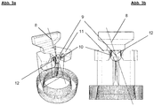
- the cryo-EM grid is arranged vertically, the sample holder according to the invention having been developed for this purpose, which enables easy handling of the grid, cf. Fig. 2a, 2b and 3a, 3b .
- the dynamic light scattering arrangement is designed for the execution of the qualification method according to the method according to the invention in such a way that the laser beam path is guided through the sample without hitting the sample carrier intended for cryoelectron microscopy.
- the laser should be positioned in such a way that the beam path leads through the sample volume without hitting the grid surface, as this can lead on the one hand to undesired scattered light through the grid and on the other hand to heating the grid and thus the sample. In addition, it must be ensured that the fluctuating scattered light interference pattern, caused by the particle movement, can be recorded by the detector.
- the sample holder according to the invention and belonging to the dynamic light scattering arrangement is designed for the execution of the qualification method according to the invention and using a dynamic light scattering arrangement in such a way that the sample holder has a receptacle for the sample carrier intended for cryoelectron microscopy, with the one provided for cryoelectron microscopy according to the invention Sample carrier the sample is applied during the qualification process.
- Fig. 1 a schematic representation of an exemplary embodiment of the DLS measuring apparatus is shown.
- Fig. 1 shows the basic DLS measurement setup consisting of the most important optical and electronic components.
- the confocal adjustment of laser 8 and detector is carried out in the optical head 6 5, which must be guaranteed for the measuring principle.
- This measurement volume 9 is positioned within the drop that adheres to the grid.
- Fig. 2a and 2b show a schematic representation of an embodiment of the grid holder 11 with the sample 12 adhering to the grid surface.
- FIG. 3a and 3b are schematic representations of an embodiment of the grid holder 11 shown with an inserted grid.
- a holder is inserted into a multiwell plate that can accommodate a grid in such a way that the laser beam 8 passes the grid, in this case parallel to the grid surface, into the sample 12 (for better clarity in Fig.3a , b not shown) meets.
- the detector looks at the focal point of the laser 8 (confocal arrangement, see Fig. 1 ).
- the sample 12 is sealed by the oil 14 in the well and therefore cannot evaporate, so the concentration ratios remain constant.
- the focal point or the measurement volume 9 within the sample 12 can be individually positioned due to the possibility of positioning within the well, which is ensured in the specific implementation by motorized X, Y and Z positioning units. This is not necessary with a correspondingly precise holder.
- a prepared cryo-EM grid (coating, charge is applied in advance) is loaded with a few microliters of the sample 12; this is usually done by manual pipetting. The same work steps are carried out here as for the further cryo-EM examination.
- the grid is then inserted into the grid holder 11. And the grid holder in turn is transferred to the container filled with paraffin oil. Sealed in this way, the sample 12 can be measured over longer periods of time (possibly several hours).
- the subsequent measurement is suitable for determining whether and, if so, when the contact with the grid surface has an effect on the sample 12.
- the DLS measurements are usually carried out as a series of individual measurements, which are then summarized as a photon count rate / time diagram or as a radius / time diagram.
- a control sample is prepared while observing the identical conditions (paraffin oil seal, temperature, measurement period, etc.), which, in contrast to sample 12, rests on a polystyrene surface (not shown).
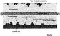
- Fig. 4a, 4b and 4c show a schematic representation of the processes during grid-induced aggregation of the sample 12 and a surface attachment of the macromolecules as a result of electrostatic attractive forces.
- Fig. 5a and 5b are schematic representations of an embodiment of the diffusion times as a function of the diffusion constants and distances shown.
- the measurements on the control sample are usually used as a comparison (control) before the grid is loaded and after the measurement series on the grid has ended. If the contact of the sample 12 with the grid surface has an adverse effect on the solubility of the sample 12, this becomes visible after a certain time as a change in the particle size or the scattered light intensity ( Fig. 5a, 5b , Photon count rate as a function of time).
- a sample 12 both on the grid and in the control should have unchanged values for the counting rate and radius distribution even over a comparatively long period of time. In this case, it can be assumed that the sample 12 does not aggregate through interactions with the grid or that the complexes disintegrate if an identical grid is loaded with this sample 12 for the shock freezing.
- Fig. 4a and b show an obvious mechanism.
- the buffer has corrosive properties, as a result of which the grid material is attacked.
- the metal ions released from the metal lattice of the grid accumulate in the sample volume.
- the copper ion concentration reaches a critical value, if this is exceeded the macromolecule aggregates rapidly.
- the time it takes to reach this critical ion concentration depends on both the buffer and the macromolecule.
- the plasma charge which is a central step in the grid preparation.
- the parameter of the charge density can be varied. It has been shown that a certain charge density value on the one hand binds only a few macromolecules to surfaces, but at the same time offers sufficient hydrophilicity of the grid surface so that the sample sufficiently covers the grid.
- DLS measurements of the drop volume of the sample 12 on the grid conclusions can be drawn about the aggregation behavior of the individual molecules directly on the grid surface.
- the triggering agent diffuses into the sample volume until the critical ion concentration is exceeded.
- the DLS measurement volume 9 serves here as a representative partial volume in order to draw conclusions about the aggregation behavior of the sample 12 in the entire sample volume. The information can be used as a reliable timer for the subsequent shock freezing process.
Landscapes
- Chemical & Material Sciences (AREA)
- General Health & Medical Sciences (AREA)
- Life Sciences & Earth Sciences (AREA)
- Health & Medical Sciences (AREA)
- Analytical Chemistry (AREA)
- Biochemistry (AREA)
- Physics & Mathematics (AREA)
- General Physics & Mathematics (AREA)
- Immunology (AREA)
- Pathology (AREA)
- Dispersion Chemistry (AREA)
- Analysing Materials By The Use Of Radiation (AREA)
- Sampling And Sample Adjustment (AREA)
Abstract
Description
- Die Erfindung betrifft das Gebiet der dynamischen Lichtstreuung, kurz DLS, und das Gebiet der Kryoelektronenmikroskopie, kurz Cryo-EM, insbesondere die Qualifizierung einer für die Kryoelektronenmikroskopie vorbereiteten Probe auf einem für die Kryoelektronenmikroskopie angeordneten Probenträger, kurz auch Probe auf einem Cryo-EM Grid.
- Bei der DLS handelt es sich um eine Analysemethode, die an gelösten oder suspendierten Proben, meist Proteine, mittels Streulichtes eines Lasers erfolgt. DLS ist ein non-invasives Verfahren, das sowohl absolute Partikelgrößen, als auch die Verteilung von Größen in einer Mischung verschiedener Partikel messen kann. Im Unterschied zu der Transmissionselektronenmikroskopie, kurz TEM, stellt das Verfahren der dynamischen Lichtstreuung zur Bestimmung des Aggregationsverhaltens in einer Probe kein bildgebendes Verfahren dar. Als Stand der Technik bezüglich der dynamischen Lichtstreuung ist die sog. in situ DLS-Technik bekannt, bei der ein fokussierter Laserstrahl direkt in eine Probe gerichtet wird, die sich in einem durchsichtigen Behältnis befindet, und die Fluktuationen des gestreuten Lichts werden quantitativ ausgewertet, wobei durch mathematische Verfahren aus diesen Interferenzerscheinungen die Partikelgröße und deren Verteilung errechnet werden.
- Weiter im Stand der Technik ist die Kryoelektronenmikroskopie bekannt, wobei Cryo-EM eine Form der Transmissionselektronenmikroskopie ist, bei der biologische Proben bei kryogenen Temperaturen ungefähr bzw. kleiner als -150 °C untersucht werden, wobei insbesondere eine Untersuchung nahe am nativen Zustand der Probe erfolgen kann, insbesondere kann die dreidimensionale Strukturaufklärung von Makromolekülen durch Einzelpartikel-Elektronenmikroskopie erfolgen.
- Vor der tatsächlichen Untersuchung einer Probe mittels Kryoelektronenmikroskopie wird diese üblicherweise zunächst auf ihre Eignung hin untersucht (qualifiziert), mit dem Ziel, die Wahrscheinlichkeit zu erhöhen, dass die mittels Kryoelektronenmikroskopie zu untersuchende Probe bzw. Teilchenart nicht verklumpt vorliegt.
- Seit Jahren wird diese Qualifizierung vorwiegend durch eine Voruntersuchung mit einem im Vergleich zur Gefrier- bzw. Kryoelektronenmikroskopie kostengünstigen Verfahren, der Transmissions-Elektronenmikroskopie, kurz TEM, gelöst, indem ein Bild der Probe mit geringerer Vergrößerung aufgezeichnet und hier die Größenverteilung anhand der Erscheinung der Partikel auf dem Bild beurteilt wird.
- Diese Herangehensweise weist jedoch einige Nachteile auf, die die Aussagekraft dieser Voruntersuchungsmethode über die Qualität einer Probe beeinträchtigt. Nachteilig ist beispielsweise, dass die Probe für dieses Qualifizierungsverfahren mittels TEM vollständig eingetrocknet sein muss, da Wasser das zur Bildgebung benötigte Vakuum im Mikroskop beeinträchtigen würde. Da Wasser jedoch häufig den Hauptbestandteil der Pufferlösung der biologischen Makromoleküle darstellt, kommt es beim Trocknen nicht selten zur Übersättigung und damit Aggregation der Probe. In dem Fall würde die TEM-Voruntersuchung ein falsches negatives Qualifizierungsresultat vorweisen, also die Probe als nicht geeignet zur Kryoelektronenmikroskopie ausweisen. Da als Kontrastmittel der TEM-Untersuchung zusätzlich Schwermetallsalze wie Uranylazetat Verwendung finden und diese an der Oberfläche von z.B. biologischen Makromolekülen, bspw. Proteinen gebunden werden können, kann die gleichartige Ladung zu Abstoßungseffekten führen. Daher kann nicht ausgeschlossen werden, dass das Protein de-aggregiert und damit ein falsch positives Qualifizierungsergebnis nach der TEM-Voruntersuchung vorliegt. TEM stellt damit keine verlässliche Voruntersuchungsmethode bzw. Qualifizierungsmethode dar, da die Probe für diese Untersuchung erheblich verändert werden muss. Somit handelt es sich um ein invasives Verfahren, bei dem die Probenbeurteilung nicht unter den gleichen Bedingungen wie die nachfolgende Cryo-EM-Aufnahme stattfindet. Die Qualifizierung mittels Transmissionselektronenmikroskopie gibt also lediglich Hinweise darauf, dass die Probe intakt sein könnte, wenn Komplexe nicht dissoziiert und Makromoleküle nicht aggregiert vorgelegen haben.
- Weitere Nachteile der Transmissionselektronenmikroskopie sind natürlich der erhebliche technische Aufwand, den eine Bildaufzeichnung mittels TEM darstellt. Hierfür sind nicht nur die Anschaffungs- und Betriebskosten von TEM selbst zu nennen, sondern auch der hohe Qualifikationsgrad des Anwenders, sowie der konstruktionsbedingte vergleichsweise geringe Probendurchsatz.
- Insgesamt ergibt sich daher die technische Aufgabe, ein zur TransmissionselektronenMikroskopie alternatives Verfahren zur Qualifizierung von für die Kryoelektronenmikroskopie vorgesehenen Proben anzugeben, dass zum einen die Nachteile der TEM überwindet und zudem noch ergänzende Probleme löst bzw. von vornherein ausschließen kann, wobei hierzu insbesondere seitens der Erfinder erkannt wurde, dass der Probenträger für eine Probe zur Kryoelektronenmikroskopie als mögliche problem- bzw. fehlerverursachende Quelle in Frage kommt. Es muss sichergestellt werden, dass bei Einzelpartikel-Elektronenmikroskopie die zu untersuchende Teilchenart nicht verklumpt bzw. Molekülkomplexe nicht dissoziiert vorliegen, was in der praktischen Anwendung ein häufig auftretendes Problem darstellt.
- Gelöst wird diese Aufgabe mit einem Qualifizierungsverfahren gemäß Hauptanspruch sowie einer dynamischen-Lichtstreuungsanordnung und entsprechend zugehörigem Probenhalter gemäß nebengeordneten Ansprüchen. Weitere vorteilhafte Ausgestaltungsvarianten finden sich in den Unteransprüchen.
- Das Qualifizierungsverfahren einer für die und mittels Kryoelektronenmikroskopie zu untersuchenden Probe ist gekennzeichnet durch das Aufbringen der Probe auf einen für die Kryoelektronenmikroskopie vorgesehenen Probenträger (Kryoelektronenmikroskopie - Probenträge, auch als Cryo-EM Grid bezeichnet) und anschließendes Untersuchen der auf dem Probenträger angeordneten Probe mittels dynamischer Lichtstreuung (DLS), wobei mittels der dynamischen Lichtstreuung eine Bestimmung der Partikelgrößenverteilung innerhalb der Probe erfolgt.
- Neu an der Erfindung ist insbesondere, dass die dynamische Lichtstreuung DLS erstmalig an Proben gemessen werden kann, die sich direkt auf einem für die Kryoelektronenmikroskopie vorgesehenen Probenträger (Kryoelektronenmikroskopie - Probenträge, auch als Cryo-EM Grid bezeichnet) befinden.
- Im Zusammenhang mit dieser Erfindung erkannten die Erfinder, dass auch der eigentliche Kryoelektronenmikroskopie - Probenträger (Cryo-EM Grid) eine verklumpende Wirkung auf die Probe ausüben kann. Idealerweise nimmt das Grid-Material selbst keinen Einfluss auf die Probe. Die bisherigen Untersuchungen haben jedoch einen Einfluss des Grid-Materials auf die Probe gezeigt, was seitens der Erfinder während den Untersuchungen herausgearbeitet wurde (siehe
Abb. 5a, 5b ). Daher ist eine Untersuchung der Probe auf dem Kryoelektronenmikroskopie - Probenträger (Cryo-EM Grid) entscheidend für eine verlässliche Beurteilung der Probenqualität. Damit werden alle internen und externen Einflüsse, die sich auf das Aggregationsverhalten und somit die Probenqualität auswirken, in einem Verfahren berücksichtigt. Veränderungen der Probe infolge von Wechselwirkungen mit dem Grid-Material resultieren häufig in einer Veränderung der Partikelgrößenverteilung, die dann mittels DLS festgestellt werden kann. Beginnend mit einer uniformen Partikelgröße kann sowohl eine Verkleinerung als auch eine Vergrößerung der Partikel, in Folge des Kontakts mit der Grid-Oberfläche, als unerwünschte Wechselwirkung auftreten. - Statt einer Abbildung der Teilchen wird ein Größen/Häufigkeitsdiagramm erhalten. Da für elektronenmikroskopische Anwendungen, im Bereich der makromolekularen Strukturaufklärung, diskrete Teilchengrößen, sowie möglichst uniforme Proben eingesetzt werden müssen, stellt DLS hier ein geeignetes Nachweisverfahren dar. Dies konnte bisher schon an Proben gezeigt werden, die mit einem herkömmlichen DLS-System untersucht wurden.
- Als Ausführungshinweis sei erwähnt, dass das eingesetzte Probenvolumen von unter einem bis zu wenigen Mikrolitern, sowie die zu bedeckende Fläche von ca. 7 Quadratmillimetern zu einer geringen Schichtdicke der Probe führt, wobei dies an Messungen mit dynamischer Lichtstreuung eine enorme Herausforderung darstellt. Zudem muss die Probe über den Messzeitraum vor Verdampfung geschützt werden, da ansonsten die Probenzusammensetzung variiert, die Probe also austrocknet, was wiederum zu den gleichen negativen Effekten wie das Trocknen der TEM-Probe führen könnte. Eine entsprechende Ausführung kann durch verschiedene Verfahren erreicht werden, nämlich beispielsweise Klimatisierung der Messkammer oder durch eine Versiegelung.
- Entscheidende Vorteile gegenüber der Voruntersuchung mittels TEM sind insbesondere:
- keine Veränderung der Probe, da ein nicht invasives in situ Verfahren zur Qualifizierung der Probe angewendet wird - kein Einfluss der Messung auf die Probe wie Erwärmen, inelastische Streuung, chemische Veränderung;
- erheblich geringerer technischer Aufwand von DLS im Vergleich zu TEM und damit Zeit- und Kostenersparnis;
- deutlich höherer Probendurchsatz und damit einhergehend die Möglichkeit mehrere Parameter in Kombinationen zu erproben;
- ferner kann eine analoge Probenbehandlung zum Schockgefrierverfahren genutzt werden; sowie
- geringere nötige Qualifikation des Anwenders.
- Es handelt sich um technische als auch um wirtschaftliche Vorteile der Erfindung, da kostengünstiger gearbeitet werden kann und erstmalig auch tatsächlich eine hochgradig verlässliche Qualifizierung der Proben für die Kryoelektronenmikroskopie erfolgen kann.
- Die Erfindung erlaubt sowohl eine qualitative Größenbestimmung von Partikeln auf dem Probenträger für die Kryoelektronenmikroskopie als auch eine quantitative Beurteilung der Größenverteilungen. Beide Eigenschaften können für die Probenbeurteilung ausgenutzt werden. Die quantitative Größenmessung wird hierbei eingesetzt, um zu beurteilen, ob bspw. ein makromolekularer Komplex intakt oder in seine Untereinhalten zerfallen vorliegt.
- Durch DLS sind zwei Richtungen der Qualität zugänglich, nämlich zum einen Homogenität der Probe (generell notwendig für die Cryo-EM-Auswertung, da es sich um ein mittelndes Verfahren handelt) und zum zweiten die absolute Größe, Sicherstellung der richtigen Größe des gewünschten Makromoleküls (z.B. Zerfall von Komplexen in homogener Form).
- Mittels der Bestimmung der Partikelgrößenverteilung kann insbesondere eine Untersuchung der Probe auf Verklumpungen erfolgen.
- Weiter kann die Probe auf und mit dem zur Qualifizierung verwendeten Probenträger mittels Kryoelektronenmikroskopie untersucht werden.
- Insbesondere kann der Laser-Strahlengang durch die Probe geführt werden ohne auf den für die Kryoelektronenmikroskopie vorgesehenen Probenträger zu treffen.
- Weiter kann in einer weiterführenden Ausführungsvariante eine Anpassung der Kryoelektronen-Probenträger-Parameter als Teil der Probenvorbereitung für Kryoelektronenmikroskopie durch Abstimmung des Kryoelektronen-Probenträger-Materials und/oder weiterer Eigenschaften des Kryoelektronen-Probenträgers erfolgen. Zur Vermeidung von Verklumpung auf dem Kryoelektronenmikroskopie Probenträger (Cryo-EM-Grid) können verschiedene Parameter variiert werden, hierzu zählen z.B. das Grid-Material, (Kupfer, Gold, Silizium, Platin), die Oberflächenbeschichtung des Grids, statische Aufladung oder aber die sog. Puffersubstanz, in welcher sich die Probe befindet. Um diese Parameter allerdings gezielt an eine Probe anpassen zu können, ist die Feststellung erforderlich, welche Auswirkung die Variationen der Parameter auf die Probe haben. Bislang erfolgte dies durch Elektronenmikroskopie selbst was jedoch ein zeit- und kostenintensives Verfahren zur Feststellung der Probenqualität darstellt. Die Messung mittels DLS direkt auf den Grids bietet hier entscheidende Vorteile, nämlich die Zeit- und Gerätekostenersparnis, die hohe Verlässlichkeit der Aussage sowie die einfache Durchführung.
- Die qualitative Größenverteilungsbestimmung kann, wie bereits beschrieben, eingesetzt werden, um die verklumpende Wirkung der Grid-Oberfläche zu erkennen und durch systematische Variation der Grid-Parameter möglichst auszuschließen. Dies würde eine Standardisierung der Anpassung der Grid-Parameter als Teil der Probenvorbereitung für Kryoelektronenmikroskopie erstmalig erlauben.
- Die Dynamische Lichtstreuungs-Anordnung (DLS-Anordnung) ist nachfolgend exemplarisch aber gleichwohl nicht zwingend beschränkend dargelegt:
Ein Laser und eine Detektoroptik sind in einem Optikkopf angeordnet, wobei das Streulicht des Lasers, hervorgerufen durch die Streuung an Partikeln, auf eine optische Faser gebündelt wird. Die Faser leitet das Streulicht zu einem Verstärker, im konkreten Fall durch einen Photomultiplier realisiert. Dieser wandelt die eingehenden Photonen in elektrische Signale um, die von einem Autokorrelator durch Anwendung mathematischer Algorithmen ausgewertet werden. Das Ergebnis ist eine Partikelgrößenverteilung, die in Form von Diagrammen dargestellt werden können, vgl.Abb. 1 . - Das Probenvolumen, das vom Laser durchdrungen wird, befindet sich erfindungsgemäß direkt auf der Oberfläche eines für die Kryoelektronenmikroskopie ausgebildeten Probenträgers, kurz Cryo-EM-Grid oder auch nur Grid.
- Vor Austrocknung wird die Probe durch eine Schicht Paraffinöl geschützt. Das Cryo-EM-Grid ist in diesem Fall vertikal angeordnet, wobei dafür der erfindungsgemäße Probenhalter entwickelt wurde, der eine einfache Handhabung des Grids ermöglicht, vgl.
Abb. 2a, 2b und3a, 3b . - Die dynamische Lichtstreuungs-Anordnung ist derart für die Ausführung des Qualifizierungsverfahrens gemäß des erfindungsgemäßen Verfahrens ausgebildet, dass der Laser-Strahlengang durch die Probe geführt ist ohne auf den für die Kryoelektronenmikroskopie vorgesehenen Probenträger zu treffen.
- Der Laser sollte so positioniert werden, dass der Strahlengang durch das Probenvolumen führt, ohne dabei auf die Grid-Oberfläche zu treffen, da dies zum einen zu unerwünschtem Streulicht durch das Grid, zum anderen zu einer Erwärmung des Grids und somit der Probe führen kann. Zusätzlich muss darauf geachtet werden, dass das fluktuierende Streulicht-Interferenzmuster, hervorgerufen durch die Partikelbewegung, vom Detektor aufgezeichnet werden kann.
- Der erfindungsgemäße und zu der dynamischen Lichtstreuungs-Anordnung zugehörige Probenhalter ist für die Ausführung des erfindungsgemäßen Qualifizierungsverfahrens und unter Verwendung einer Dynamischen Lichtstreuungs-Anordnung derart ausgebildet, dass der Probenhalter eine Aufnahme des für die Kryoelektronenmikroskopie vorgesehenen Probenträgers aufweist, wobei erfindungsgemäß auf dem für die Kryoelektronenmikroskopie vorgesehenen Probenträger die Probe bei der Durchführung des Qualifizierungsverfahrens aufgebracht ist.
- Nachfolgend werden Ausführungsbeispiele der Erfindung anhand der beiliegenden Abbildungen in der Beschreibung detailliert beschrieben, wobei diese die Erfindung erläutern sollen und nicht beschränkend zu werten sind:
Es zeigen: - Abb. 1
- eine schematische Darstellung eines Ausführungsbeispiels der DLS Messapparatur;
- Abb. 2a, b
- eine schematische Darstellung eines Ausführungsbeispiels des Grid-Halters 11 mit der Probe 12, die sich ihrerseits auf dem Grid befindet;
- Abb. 3a, b
- eine schematische Darstellung eines Ausführungsbeispiels des Grid-Halters 11 mit eingesetztem Grid;
- Abb. 4a, b
- eine schematische Darstellung der Vorgänge bei Grid-induzierter Aggregation der Probe 12 und
- Abb. 5a, b
- eine schematische Darstellung eines Ausführungsbeispiels der Diffusionszeiten in Abhängigkeit der Diffusionskonstanten und Distanzen.
- An dieser Stelle soll darauf hingewiesen werden, dass das Ausführungsbeispiel bzw. die Ausführungsformen der Erläuterung dienen und nicht zwingend beschränkend zu werten sind.
- In
Abb. 1 ist eine schematische Darstellung eines Ausführungsbeispiels der DLS Messapparatur dargestellt. -
Abb. 1 zeigt den prinzipiellen DLS-Messaufbau bestehend aus den wichtigsten Optik- und Elektronikkomponenten. Im Optikkopf 6 wird die konfokale Justierung von Laser 8 und Detektor 5, die für das Messprinzip gewährleistet werden muss, realisiert. Dieses Messvolumen 9 wird innerhalb des Tropfens, der auf dem Grid haftet, positioniert. -
Abb. 2a und 2b zeigen eine schematische Darstellung eines Ausführungsbeispiels des Grid-Halters 11 mit der Probe 12, die an der Grid-Oberfläche haftet. - In
Abb. 3a und 3b sind schematische Darstellungen eines Ausführungsbeispiels des Grid-Halters 11 mit eingesetztem Grid gezeigt. - In oben dargestellter Ausführung (
Abb. 2a, 2b und3a, 3b ) wird in eine Multiwell-Platte ein Halter eingesetzt, der ein Grid so aufnehmen kann, dass der Laserstrahl 8 am Grid vorbei, in diesem Fall parallel zur Grid-Oberfläche, in die Probe 12 (zur besseren Übersichtlichkeit inAbb. 3a ,b nicht dargestellt) trifft. Der Detektor blickt auf den Fokuspunkt des Lasers 8 (konfokale Anordnung, sieheAbb. 1 ). Die Probe 12 wird durch das in dem Well befindliche Öl 14 versiegelt und kann daher nicht evaporieren, die Konzentrationsverhältnisse bleiben also konstant. Durch die Positioniermöglichkeit innerhalb des Wells, in der konkreten Realisierung durch motorisierte X, Y- und Z- Positioniereinheiten gewährleistet, kann der Fokuspunkt bzw. das Messvolumen 9 innerhalb der Probe 12 individuell positioniert werden. Bei entsprechend genauem Halter ist dies nicht notwendig. - Ein vorbereitetes Cryo-EM-Grid (Beschichtung, Ladung werden vorab aufgebracht) wird mit einigen Mikrolitern der Probe 12 beladen, üblicherweise geschieht dies durch manuelles Pipettieren. Hierbei werden die gleichen Arbeitsschritte wie bei der weiteren Cryo-EM-Untersuchung durchgeführt. Anschließend wird das Grid in den Grid-Halter 11 eingesetzt. Und der Grid-Halter seinerseits in den mit Paraffinöl gefüllten Behälter überführt. Auf diese Weise versiegelt, kann an der Probe 12 über längere Zeiträume (u.U. mehrere Stunden) gemessen werden. Die anschließende Messung ist geeignet, um festzustellen, ob und ggf. wann der Kontakt mit der Grid-Oberfläche eine Auswirkung auf die Probe 12 hat. Dabei werden die DLS-Messungen üblicherweise als eine Serie von Einzelmessungen durchgeführt, die anschließend zusammengefasst als Photonenzählrate/Zeit-Diagramm oder als Radius/Zeit-Diagramm dargestellt werden. Üblicherweise wird eine Kontrollprobe unter Einhaltung der identischen Bedingungen (Paraffinölversiegelung, Temperatur, Messzeitraum etc.) angesetzt, die im Unterschied zur Probe 12 auf einer Polystyroloberfläche aufliegt (nicht dargestellt).
-
Abb. 4a, 4b und4c zeigen eine schematische Darstellung der Vorgänge bei Grid-induzierter Aggregation der Probe 12 sowie eine Oberflächenanlagerung der Makromoleküle in Folge elektrostatischer Anziehungskräfte. - In
Abb. 5a und 5b sind schematische Darstellungen eines Ausführungsbeispiels der Diffusionszeiten in Abhängigkeit der Diffusionskonstanten und Distanzen gezeigt. - Die Messungen an der Kontrollprobe werden in der Regel vor Beladung des Grids sowie nach beendeter Messreihe auf dem Grid als Vergleich (Kontrolle) herangezogen. Wirkt sich der Kontakt der Probe 12 mit der Grid-Oberfläche ungünstig für die Löslichkeit der Probe 12 aus, so wird dies nach einer gewissen Zeit als Veränderung der Partikelgröße bzw. Streulichtintensität sichtbar (
Abb. 5a, 5b , Photonenzählrate in Abhängigkeit der Zeit). Idealerweise sollte eine Probe 12, sowohl auf dem Grid als auch in der Kontrolle, selbst über einen vergleichsweise langen Zeitraum, unveränderte Werte der Zählrate und Radiusverteilung aufweisen. In diesem Fall kann davon ausgegangen werden, dass die Probe 12 nicht durch Wechselwirkungen mit dem Grid aggregiert bzw. die Komplexe zerfallen, wenn ein identisches Grid für die Schockgefrierung mit dieser Probe 12 beladen wird. Mehrere Erklärungsmodelle sind denkbar, weshalb der Kontakt der Probe 12 mit der Grid-Oberfläche, Auswirkungen auf das Aggregationsverhalten der Probe hat.Abb. 4a und b zeigen einen naheligenden Mechanismus auf. Der Puffer weist korrosive Eigenschaften auf, wodurch das Grid-Material angegriffen wird. Die sich aus dem Metallgitter des Grids lösenden Metallionen reichen sich dabei im Probenvolumen an. In einer gewissen Zeit erreicht die Kupferionenkonzentration einen kritischen Wert, wird dieser überschritten erfolgt eine rasche Aggregation des Makromoleküls. Die Zeit die zum Erreichen dieser kritischen lonenkonzenration erreicht wird ist sowohl Pufferals auch Makromolekülabhängig. Darüber hinaus gibt es noch einen weiteren aggregierenden Effekt und das ist die Plasmaaufladung, die einen zentralen Arbeitsschritt der Grid-Vorbereitung darstellt. Hier kann der Parameter der Ladungsdichte variiert werden. Es hat sich gezeigt, dass ein bestimmter Ladungsdichtewert zum einen nur wenig Makromoleküle an Oberflächen bindet, zugleich aber noch ausreichend Hydrophilie der Grid-Oberfläche bietet, so dass die Probe das Grid ausreichend bedeckt. - Durch DLS-Messungen der im Tropfenvolumen der Probe 12 auf dem Grid lassen sich Rückschlüsse ziehen auf das Aggregationsverhalten der Einzelmoleküle direkt an der Grid-Oberfläche. Bei t0 wird mittels DLS noch keine Aggregation detektiert. Das auslösende Agens diffundiert in das Probenvolumen, bis die kritische lonenkonzentration überschritten ist. Das DLS-Messvolumen 9 dient hier als repräsentatives Teilvolumen, um Rückschlüsse auf das Aggregationsverhalten der Probe 12 im gesamten Probenvolumen zu ziehen. Die Information kann als verlässlicher Zeitgeber für den späteren Schockgefriervorgang verwendet werden.
-
- 1
- Anzeigegerät
- 2
- Autokorrelator
- 3
- Photomultiplier
- 4
- Lichtleiter
- 5
- Detektoroptik
- 6
- Optikkopf
- 7
- Streulichtpfad
- 8
- DLS-Laserstrahl
- 9
- Detektorfokus / Messvolumen
- 10
- Kryoelektronenmikroskopie-Träger (Grid)
- 11
- Grid-Halter [DLS] (für das Cryo-EM-Grid mit Probe)
- 12
- Probe
- 13
- Behältnis
- 14
- Paraffinöl
Claims (6)
- Qualifizierungsverfahren einer für die und mittels Kryoelektronenmikroskopie zu untersuchenden Probe (12),
gekennzeichnet durch
das Aufbringen der Probe (12) auf einen für die Kryoelektronenmikroskopie vorgesehenen Probenträger (10) und anschließendes Untersuchen der auf dem Probenträger angeordneten Probe (12) mittels dynamischer Lichtstreuung, wobei mittels der dynamischen Lichtstreuung eine Bestimmung der Partikelgrößenverteilung innerhalb der Probe (12) erfolgt. - Qualifizierungsverfahren nach dem vorangehenden Anspruch,
dadurch gekennzeichnet, dass
mittels der Bestimmung der Partikelgrößenverteilung eine Untersuchung der Probe (12) auf Verklumpungen und/oder Dissoziation von Molekülkomplexen erfolgt. - Qualifizierungsverfahren nach einem der vorangehenden Ansprüche,
dadurch gekennzeichnet, dass
die Probe (12) auf und mit dem zur Qualifizierung verwendeten Probenträger mittels Kryoelektronenmikroskopie untersucht wird. - Qualifizierungsverfahren nach einem der vorangehenden Ansprüche,
dadurch gekennzeichnet, dass
der Laser-Strahlengang (8) durch die Probe (12) geführt wird ohne auf den für die Kryoelektronenmikroskopie vorgesehenen Probenträger (10) zu treffen. - Qualifizierungsverfahren nach einem der vorangehenden Ansprüche,
dadurch gekennzeichnet, dass
eine Anpassung der Kryoelektronen-Probenträger-Parameter als Teil der Probenvorbereitung für Kryoelektronenmikroskopie durch Abstimmung des Kryoelektronen-Probenträger-Materials und/oder weiterer Eigenschaften des Kryoelektronen-Probenträgers und/oder Pufferbedingungen der Probe erfolgt. - Probenhalter ausgebildet für die Ausführung des Qualifizierungsverfahrens gemäß einem der vorangehenden Verfahrensansprüche und unter Verwendung einer Dynamischen Lichtstreuungs-Anordnung,
dadurch gekennzeichnet, dass
der Probenhalter eine Aufnahme des für die Kryoelektronenmikroskopie vorgesehenen Probenträgers aufweist, wobei erfindungsgemäß auf dem für die Kryoelektronenmikroskopie vorgesehenen Probenträger (10) die Probe (12) aufgebracht ist.
Priority Applications (2)
| Application Number | Priority Date | Filing Date | Title |
|---|---|---|---|
| EP19175196.5A EP3739321B1 (de) | 2019-05-17 | 2019-05-17 | Qualifizierungsverfahren für kryoelektronenmikroskopie-proben sowie dazugehöriger probenhalter |
| US15/931,776 US11609171B2 (en) | 2019-05-17 | 2020-05-14 | Qualification process for cryo-electron microscopy samples as well as related sample holder |
Applications Claiming Priority (1)
| Application Number | Priority Date | Filing Date | Title |
|---|---|---|---|
| EP19175196.5A EP3739321B1 (de) | 2019-05-17 | 2019-05-17 | Qualifizierungsverfahren für kryoelektronenmikroskopie-proben sowie dazugehöriger probenhalter |
Publications (2)
| Publication Number | Publication Date |
|---|---|
| EP3739321A1 true EP3739321A1 (de) | 2020-11-18 |
| EP3739321B1 EP3739321B1 (de) | 2023-03-08 |
Family
ID=66625002
Family Applications (1)
| Application Number | Title | Priority Date | Filing Date |
|---|---|---|---|
| EP19175196.5A Active EP3739321B1 (de) | 2019-05-17 | 2019-05-17 | Qualifizierungsverfahren für kryoelektronenmikroskopie-proben sowie dazugehöriger probenhalter |
Country Status (2)
| Country | Link |
|---|---|
| US (1) | US11609171B2 (de) |
| EP (1) | EP3739321B1 (de) |
Families Citing this family (2)
| Publication number | Priority date | Publication date | Assignee | Title |
|---|---|---|---|---|
| DE102020126737A1 (de) * | 2020-10-12 | 2022-04-14 | Carl Zeiss Microscopy Gmbh | Verfahren und Mikroskop zum Erzeugen eines Übersichtsbildes einer Probe |
| CN113720842B (zh) * | 2021-08-30 | 2023-04-18 | 武汉大学 | 一种生物样品成像辅助装置、生物样品成像系统及方法 |
Family Cites Families (28)
| Publication number | Priority date | Publication date | Assignee | Title |
|---|---|---|---|---|
| CZ20013103A3 (cs) * | 1999-03-02 | 2002-01-16 | The Liposome Company, Inc. | Způsob zapouzdřování bioaktivních komplexů do liposomů |
| GB2429058B (en) * | 2004-03-06 | 2008-12-03 | Michael Trainer | Method and apparatus for determining the size and shape of particles |
| US9732337B2 (en) * | 2009-06-16 | 2017-08-15 | The United Stated of America, as represented by the Secretary, Department of Health & Human Services | RNA nanoparticles and nanotubes |
| US9644038B2 (en) * | 2011-12-21 | 2017-05-09 | The Regents Of The University Of California | Apolipoprotein nanodiscs with telodendrimer |
| US9884893B2 (en) * | 2012-05-21 | 2018-02-06 | Distributed Bio, Inc. | Epitope focusing by variable effective antigen surface concentration |
| US10172795B2 (en) * | 2012-12-12 | 2019-01-08 | University of Pittsburgh—of the Commonwealth System of Higher Education | Formulations and carrier systems including compound interactive domains |
| CA2919724C (en) * | 2013-08-20 | 2018-06-19 | Advanced Polymer Monitoring Technologies, Inc. | Characterization of polymer and colloid solutions |
| US10301621B2 (en) * | 2013-09-17 | 2019-05-28 | The United States Of America, As Represented By The Secretary, Department Of Health And Human Services | Multifunctional RNA nanoparticles and methods of use |
| DE102014007355B3 (de) * | 2014-05-19 | 2015-08-20 | Particle Metrix Gmbh | Verfahren der Partikel Tracking Aalyse mit Hilfe von Streulicht (PTA) und eine Vorrichtung zur Erfassung und Charakterisierung von Partikeln in Flüssigkeiten aller Art in der Größenordnung von Nanometern |
| US10835493B2 (en) * | 2015-04-20 | 2020-11-17 | Academia Sinica | Platelet-like proteo-microparticles and method of using such in drug delivery |
| US10456452B2 (en) * | 2015-07-02 | 2019-10-29 | Poseida Therapeutics, Inc. | Compositions and methods for improved encapsulation of functional proteins in polymeric vesicles |
| GB201516851D0 (en) * | 2015-09-23 | 2015-11-04 | Malvern Instr Ltd | Cuvette carrier |
| US11002655B2 (en) * | 2015-09-23 | 2021-05-11 | Malvern Panalytical Limited | Cuvette carrier |
| GB201604460D0 (en) * | 2016-03-16 | 2016-04-27 | Malvern Instr Ltd | Dynamic light scattering |
| AU2017324718B2 (en) * | 2016-09-09 | 2022-09-29 | Irisys, Inc. | Lipsomal anticancer compositions |
| EP3309536A1 (de) * | 2016-10-11 | 2018-04-18 | Malvern Panalytical Limited | Partikelcharakterisierungsinstrument |
| DE102016013236B4 (de) * | 2016-11-07 | 2020-07-16 | Particle Metrix Gmbh | Vorrichtung und Verfahren zum Messen der Konzentration, der Größe und des Zetapotentials von Nanopartikeln in Flüssigkeiten im Streulichtmodus und im Fluoreszenzmodus |
| WO2018092573A1 (ja) * | 2016-11-16 | 2018-05-24 | 株式会社堀場製作所 | 粒子径分布測定装置、粒子径分布測定方法、及び粒子径分布測定装置用プログラム |
| US11415499B2 (en) * | 2016-11-17 | 2022-08-16 | Horiba, Ltd. | Particle size distribution measurement device and program for a particle size distribution measurement device |
| EP3379232A1 (de) * | 2017-03-23 | 2018-09-26 | Malvern Panalytical Limited | Partikelcharakterisierung |
| US11207422B2 (en) * | 2017-05-02 | 2021-12-28 | Lawrence Livermore National Security, Llc | MOMP telonanoparticles, and related compositions, methods and systems |
| ES2774703T3 (es) * | 2017-06-27 | 2020-07-22 | Univ Graz Medizinische | Método y dispositivo para analizar una muestra fluídica con partículas dispersadas |
| IT201700073456A1 (it) * | 2017-06-30 | 2018-12-30 | Eos S R L | Metodo per la caratterizzazione di oggetti mediante analisi della radiazione diffusa e relativa strumentazione. |
| EP3720568B1 (de) * | 2017-12-08 | 2022-01-12 | The Procter & Gamble Company | Screening-verfahren für milde hautreiniger |
| EP3521806B1 (de) * | 2018-02-06 | 2024-12-04 | Malvern Panalytical Limited | Dynamische mehrwinkellichtstreuung |
| GB201803523D0 (en) * | 2018-03-05 | 2018-04-18 | Malvern Panalytical Ltd | Improved particle sizing by optical diffraction |
| WO2019230624A1 (ja) * | 2018-06-01 | 2019-12-05 | 株式会社堀場製作所 | 粒子径分布測定装置及び粒子径分布測定装置用プログラム |
| JP7233980B2 (ja) * | 2019-03-08 | 2023-03-07 | キオクシア株式会社 | 粒子計測方法及び検出液 |
-
2019
- 2019-05-17 EP EP19175196.5A patent/EP3739321B1/de active Active
-
2020
- 2020-05-14 US US15/931,776 patent/US11609171B2/en active Active
Non-Patent Citations (1)
| Title |
|---|
| A MEYER ET AL: "A time-efficient identification of the best conditions for cryo-EM, NMR, SAXS and crystallization applying in situ DLS", INEXT MEETS INDUSTRY, 5 March 2018 (2018-03-05), Grenoble - France, XP055633814, Retrieved from the Internet <URL:http://www.esrf.eu/files/live/sites/www/files/events/conferences/2018/iNEXT%20meets%20industry/abstractsforposters/Meyer.pdf> [retrieved on 20191018] * |
Also Published As
| Publication number | Publication date |
|---|---|
| EP3739321B1 (de) | 2023-03-08 |
| US20200363345A1 (en) | 2020-11-19 |
| US11609171B2 (en) | 2023-03-21 |
Similar Documents
| Publication | Publication Date | Title |
|---|---|---|
| EP3146308B1 (de) | Verfahren der partikel trackinq analyse mit hilfe von streulicht (pta) und eine vorrichtung zur erfassung und charakterisierung von partikeln in flüssigkeiten aller art in der grössenordnung von nanometern | |
| AT515577B1 (de) | Gemeinsamer Strahlungspfad zum Ermitteln von Partikel-information durch Direktbildauswertung und durch Differenzbildanalyse | |
| DE3146423C2 (de) | ||
| DE69921463T2 (de) | Verfahren um blutzellzählungen durchzuführen | |
| DE2261695C2 (de) | Vorrichtung zur Schnellanalyse und zum Sortieren kleiner Teilchen | |
| DE102020100020A1 (de) | Verfahren und Vorrichtung für die Bestimmung von Merkmalen von Partikeln durch multiparametrische Erfassung von Streulicht- und Extinktionssignalen | |
| DE69632998T2 (de) | Hochempfindliches, genaues und präzises automatisiertes Messverfahren und Vorrichtung zur Identifizierung und Quantifizierung von Blutplättchen und zur Bestimmung des Blutplättchenaktivitätszustands unter Verwendung von Ganzblutproben | |
| DE112011105007B4 (de) | Probenhalter für ein Elektronenmikroskop und Probenuntersuchungsverfahren | |
| EP3739321B1 (de) | Qualifizierungsverfahren für kryoelektronenmikroskopie-proben sowie dazugehöriger probenhalter | |
| EP2102886B1 (de) | Elektronenmikroskop und ein verfahren zur messung der defokusstreuung oder der grenzauflösung | |
| DE102013102535A1 (de) | Verbund-ladungspartikelstrahl-vorrichtung | |
| EP3374755B1 (de) | Lichtmikroskop und verfahren zum bestimmen einer wellenlängenabhängigen brechzahl eines probenmediums | |
| WO2015028365A1 (de) | Analyseverfahren zur ermittlung der typen und konzentrationen biologischer partikel | |
| DE2440376A1 (de) | Teilchengroessen-analyse von polydispersen systemen mit hilfe der laserlichtstreuung | |
| EP3133384A2 (de) | Vorrichtung und verfahren zur thermo-optischen untersuchung von proben | |
| DE112016006056T5 (de) | Betrachtungsvorrichtung | |
| EP0425809A2 (de) | Verfahren zum Bestimmen des Permeationsverhaltens | |
| DE19733784C2 (de) | Verfahren und Vorrichtung zur Bestimmung der Verteilung der Feststoffdichte von Einzelpartikeln in einem Partikelkollektiv | |
| DE60115591T2 (de) | Verfahren zur Messung des Volumens von einzelnen roten Blutkörperchen | |
| AT527236B1 (de) | Verfahren zum Analysieren einer Probe sowie Vorrichtung hierzu | |
| WO2016102152A1 (de) | Verfahren zum quantitativen und qualitativen erfassen von partikeln in flüssigkeit | |
| DE102007060438A1 (de) | Untersuchung einzelner biologischer Zellen | |
| DE19931128A1 (de) | Verfahren und Vorrichtung zur Messung der Korrosionsschutzwirkung von Beschichtungen und Inhibitoren | |
| DE102008042179B9 (de) | Verfahren zur Analyse einer Probe | |
| DE102020115491B4 (de) | Verfahren zur Analyse einer Partikelansammlung auf einer Membran, Vorrichtung zur automatisierten Analyse und Probenvorbereitungseinheit dafür |
Legal Events
| Date | Code | Title | Description |
|---|---|---|---|
| PUAI | Public reference made under article 153(3) epc to a published international application that has entered the european phase |
Free format text: ORIGINAL CODE: 0009012 |
|
| STAA | Information on the status of an ep patent application or granted ep patent |
Free format text: STATUS: THE APPLICATION HAS BEEN PUBLISHED |
|
| AK | Designated contracting states |
Kind code of ref document: A1 Designated state(s): AL AT BE BG CH CY CZ DE DK EE ES FI FR GB GR HR HU IE IS IT LI LT LU LV MC MK MT NL NO PL PT RO RS SE SI SK SM TR |
|
| AX | Request for extension of the european patent |
Extension state: BA ME |
|
| STAA | Information on the status of an ep patent application or granted ep patent |
Free format text: STATUS: REQUEST FOR EXAMINATION WAS MADE |
|
| 17P | Request for examination filed |
Effective date: 20210512 |
|
| RBV | Designated contracting states (corrected) |
Designated state(s): AL AT BE BG CH CY CZ DE DK EE ES FI FR GB GR HR HU IE IS IT LI LT LU LV MC MK MT NL NO PL PT RO RS SE SI SK SM TR |
|
| GRAP | Despatch of communication of intention to grant a patent |
Free format text: ORIGINAL CODE: EPIDOSNIGR1 |
|
| STAA | Information on the status of an ep patent application or granted ep patent |
Free format text: STATUS: GRANT OF PATENT IS INTENDED |
|
| GRAJ | Information related to disapproval of communication of intention to grant by the applicant or resumption of examination proceedings by the epo deleted |
Free format text: ORIGINAL CODE: EPIDOSDIGR1 |
|
| STAA | Information on the status of an ep patent application or granted ep patent |
Free format text: STATUS: REQUEST FOR EXAMINATION WAS MADE |
|
| INTG | Intention to grant announced |
Effective date: 20220913 |
|
| INTC | Intention to grant announced (deleted) | ||
| GRAP | Despatch of communication of intention to grant a patent |
Free format text: ORIGINAL CODE: EPIDOSNIGR1 |
|
| STAA | Information on the status of an ep patent application or granted ep patent |
Free format text: STATUS: GRANT OF PATENT IS INTENDED |
|
| INTG | Intention to grant announced |
Effective date: 20221121 |
|
| GRAS | Grant fee paid |
Free format text: ORIGINAL CODE: EPIDOSNIGR3 |
|
| GRAA | (expected) grant |
Free format text: ORIGINAL CODE: 0009210 |
|
| STAA | Information on the status of an ep patent application or granted ep patent |
Free format text: STATUS: THE PATENT HAS BEEN GRANTED |
|
| AK | Designated contracting states |
Kind code of ref document: B1 Designated state(s): AL AT BE BG CH CY CZ DE DK EE ES FI FR GB GR HR HU IE IS IT LI LT LU LV MC MK MT NL NO PL PT RO RS SE SI SK SM TR |
|
| REG | Reference to a national code |
Ref country code: CH Ref legal event code: EP Ref country code: AT Ref legal event code: REF Ref document number: 1552891 Country of ref document: AT Kind code of ref document: T Effective date: 20230315 |
|
| REG | Reference to a national code |
Ref country code: DE Ref legal event code: R096 Ref document number: 502019007131 Country of ref document: DE |
|
| REG | Reference to a national code |
Ref country code: IE Ref legal event code: FG4D Free format text: LANGUAGE OF EP DOCUMENT: GERMAN |
|
| REG | Reference to a national code |
Ref country code: LT Ref legal event code: MG9D |
|
| REG | Reference to a national code |
Ref country code: NL Ref legal event code: MP Effective date: 20230308 |
|
| PG25 | Lapsed in a contracting state [announced via postgrant information from national office to epo] |
Ref country code: RS Free format text: LAPSE BECAUSE OF FAILURE TO SUBMIT A TRANSLATION OF THE DESCRIPTION OR TO PAY THE FEE WITHIN THE PRESCRIBED TIME-LIMIT Effective date: 20230308 Ref country code: NO Free format text: LAPSE BECAUSE OF FAILURE TO SUBMIT A TRANSLATION OF THE DESCRIPTION OR TO PAY THE FEE WITHIN THE PRESCRIBED TIME-LIMIT Effective date: 20230608 Ref country code: LV Free format text: LAPSE BECAUSE OF FAILURE TO SUBMIT A TRANSLATION OF THE DESCRIPTION OR TO PAY THE FEE WITHIN THE PRESCRIBED TIME-LIMIT Effective date: 20230308 Ref country code: LT Free format text: LAPSE BECAUSE OF FAILURE TO SUBMIT A TRANSLATION OF THE DESCRIPTION OR TO PAY THE FEE WITHIN THE PRESCRIBED TIME-LIMIT Effective date: 20230308 Ref country code: HR Free format text: LAPSE BECAUSE OF FAILURE TO SUBMIT A TRANSLATION OF THE DESCRIPTION OR TO PAY THE FEE WITHIN THE PRESCRIBED TIME-LIMIT Effective date: 20230308 Ref country code: ES Free format text: LAPSE BECAUSE OF FAILURE TO SUBMIT A TRANSLATION OF THE DESCRIPTION OR TO PAY THE FEE WITHIN THE PRESCRIBED TIME-LIMIT Effective date: 20230308 |
|
| PG25 | Lapsed in a contracting state [announced via postgrant information from national office to epo] |
Ref country code: SE Free format text: LAPSE BECAUSE OF FAILURE TO SUBMIT A TRANSLATION OF THE DESCRIPTION OR TO PAY THE FEE WITHIN THE PRESCRIBED TIME-LIMIT Effective date: 20230308 Ref country code: NL Free format text: LAPSE BECAUSE OF FAILURE TO SUBMIT A TRANSLATION OF THE DESCRIPTION OR TO PAY THE FEE WITHIN THE PRESCRIBED TIME-LIMIT Effective date: 20230308 Ref country code: GR Free format text: LAPSE BECAUSE OF FAILURE TO SUBMIT A TRANSLATION OF THE DESCRIPTION OR TO PAY THE FEE WITHIN THE PRESCRIBED TIME-LIMIT Effective date: 20230609 Ref country code: FI Free format text: LAPSE BECAUSE OF FAILURE TO SUBMIT A TRANSLATION OF THE DESCRIPTION OR TO PAY THE FEE WITHIN THE PRESCRIBED TIME-LIMIT Effective date: 20230308 |
|
| PG25 | Lapsed in a contracting state [announced via postgrant information from national office to epo] |
Ref country code: SM Free format text: LAPSE BECAUSE OF FAILURE TO SUBMIT A TRANSLATION OF THE DESCRIPTION OR TO PAY THE FEE WITHIN THE PRESCRIBED TIME-LIMIT Effective date: 20230308 Ref country code: RO Free format text: LAPSE BECAUSE OF FAILURE TO SUBMIT A TRANSLATION OF THE DESCRIPTION OR TO PAY THE FEE WITHIN THE PRESCRIBED TIME-LIMIT Effective date: 20230308 Ref country code: PT Free format text: LAPSE BECAUSE OF FAILURE TO SUBMIT A TRANSLATION OF THE DESCRIPTION OR TO PAY THE FEE WITHIN THE PRESCRIBED TIME-LIMIT Effective date: 20230710 Ref country code: EE Free format text: LAPSE BECAUSE OF FAILURE TO SUBMIT A TRANSLATION OF THE DESCRIPTION OR TO PAY THE FEE WITHIN THE PRESCRIBED TIME-LIMIT Effective date: 20230308 Ref country code: CZ Free format text: LAPSE BECAUSE OF FAILURE TO SUBMIT A TRANSLATION OF THE DESCRIPTION OR TO PAY THE FEE WITHIN THE PRESCRIBED TIME-LIMIT Effective date: 20230308 |
|
| PG25 | Lapsed in a contracting state [announced via postgrant information from national office to epo] |
Ref country code: SK Free format text: LAPSE BECAUSE OF FAILURE TO SUBMIT A TRANSLATION OF THE DESCRIPTION OR TO PAY THE FEE WITHIN THE PRESCRIBED TIME-LIMIT Effective date: 20230308 Ref country code: PL Free format text: LAPSE BECAUSE OF FAILURE TO SUBMIT A TRANSLATION OF THE DESCRIPTION OR TO PAY THE FEE WITHIN THE PRESCRIBED TIME-LIMIT Effective date: 20230308 Ref country code: IS Free format text: LAPSE BECAUSE OF FAILURE TO SUBMIT A TRANSLATION OF THE DESCRIPTION OR TO PAY THE FEE WITHIN THE PRESCRIBED TIME-LIMIT Effective date: 20230708 |
|
| REG | Reference to a national code |
Ref country code: DE Ref legal event code: R097 Ref document number: 502019007131 Country of ref document: DE |
|
| REG | Reference to a national code |
Ref country code: CH Ref legal event code: PL |
|
| PLBE | No opposition filed within time limit |
Free format text: ORIGINAL CODE: 0009261 |
|
| STAA | Information on the status of an ep patent application or granted ep patent |
Free format text: STATUS: NO OPPOSITION FILED WITHIN TIME LIMIT |
|
| PG25 | Lapsed in a contracting state [announced via postgrant information from national office to epo] |
Ref country code: MC Free format text: LAPSE BECAUSE OF FAILURE TO SUBMIT A TRANSLATION OF THE DESCRIPTION OR TO PAY THE FEE WITHIN THE PRESCRIBED TIME-LIMIT Effective date: 20230308 |
|
| REG | Reference to a national code |
Ref country code: BE Ref legal event code: MM Effective date: 20230531 |
|
| PG25 | Lapsed in a contracting state [announced via postgrant information from national office to epo] |
Ref country code: SI Free format text: LAPSE BECAUSE OF FAILURE TO SUBMIT A TRANSLATION OF THE DESCRIPTION OR TO PAY THE FEE WITHIN THE PRESCRIBED TIME-LIMIT Effective date: 20230308 Ref country code: MC Free format text: LAPSE BECAUSE OF FAILURE TO SUBMIT A TRANSLATION OF THE DESCRIPTION OR TO PAY THE FEE WITHIN THE PRESCRIBED TIME-LIMIT Effective date: 20230308 Ref country code: LU Free format text: LAPSE BECAUSE OF NON-PAYMENT OF DUE FEES Effective date: 20230517 Ref country code: LI Free format text: LAPSE BECAUSE OF NON-PAYMENT OF DUE FEES Effective date: 20230531 Ref country code: DK Free format text: LAPSE BECAUSE OF FAILURE TO SUBMIT A TRANSLATION OF THE DESCRIPTION OR TO PAY THE FEE WITHIN THE PRESCRIBED TIME-LIMIT Effective date: 20230308 Ref country code: CH Free format text: LAPSE BECAUSE OF NON-PAYMENT OF DUE FEES Effective date: 20230531 |
|
| 26N | No opposition filed |
Effective date: 20231211 |
|
| REG | Reference to a national code |
Ref country code: IE Ref legal event code: MM4A |
|
| PG25 | Lapsed in a contracting state [announced via postgrant information from national office to epo] |
Ref country code: IE Free format text: LAPSE BECAUSE OF NON-PAYMENT OF DUE FEES Effective date: 20230517 |
|
| PG25 | Lapsed in a contracting state [announced via postgrant information from national office to epo] |
Ref country code: IE Free format text: LAPSE BECAUSE OF NON-PAYMENT OF DUE FEES Effective date: 20230517 |
|
| PG25 | Lapsed in a contracting state [announced via postgrant information from national office to epo] |
Ref country code: IT Free format text: LAPSE BECAUSE OF FAILURE TO SUBMIT A TRANSLATION OF THE DESCRIPTION OR TO PAY THE FEE WITHIN THE PRESCRIBED TIME-LIMIT Effective date: 20230308 Ref country code: FR Free format text: LAPSE BECAUSE OF NON-PAYMENT OF DUE FEES Effective date: 20230531 Ref country code: BE Free format text: LAPSE BECAUSE OF NON-PAYMENT OF DUE FEES Effective date: 20230531 |
|
| PG25 | Lapsed in a contracting state [announced via postgrant information from national office to epo] |
Ref country code: BG Free format text: LAPSE BECAUSE OF FAILURE TO SUBMIT A TRANSLATION OF THE DESCRIPTION OR TO PAY THE FEE WITHIN THE PRESCRIBED TIME-LIMIT Effective date: 20230308 |
|
| PG25 | Lapsed in a contracting state [announced via postgrant information from national office to epo] |
Ref country code: BG Free format text: LAPSE BECAUSE OF FAILURE TO SUBMIT A TRANSLATION OF THE DESCRIPTION OR TO PAY THE FEE WITHIN THE PRESCRIBED TIME-LIMIT Effective date: 20230308 |
|
| PGFP | Annual fee paid to national office [announced via postgrant information from national office to epo] |
Ref country code: DE Payment date: 20250519 Year of fee payment: 7 |
|
| PGFP | Annual fee paid to national office [announced via postgrant information from national office to epo] |
Ref country code: GB Payment date: 20250522 Year of fee payment: 7 |
|
| REG | Reference to a national code |
Ref country code: AT Ref legal event code: MM01 Ref document number: 1552891 Country of ref document: AT Kind code of ref document: T Effective date: 20240517 |
|
| PG25 | Lapsed in a contracting state [announced via postgrant information from national office to epo] |
Ref country code: AT Free format text: LAPSE BECAUSE OF NON-PAYMENT OF DUE FEES Effective date: 20240517 |
|
| PG25 | Lapsed in a contracting state [announced via postgrant information from national office to epo] |
Ref country code: CY Free format text: LAPSE BECAUSE OF FAILURE TO SUBMIT A TRANSLATION OF THE DESCRIPTION OR TO PAY THE FEE WITHIN THE PRESCRIBED TIME-LIMIT; INVALID AB INITIO Effective date: 20190517 |
|
| PG25 | Lapsed in a contracting state [announced via postgrant information from national office to epo] |
Ref country code: HU Free format text: LAPSE BECAUSE OF FAILURE TO SUBMIT A TRANSLATION OF THE DESCRIPTION OR TO PAY THE FEE WITHIN THE PRESCRIBED TIME-LIMIT; INVALID AB INITIO Effective date: 20190517 |
|
| PG25 | Lapsed in a contracting state [announced via postgrant information from national office to epo] |
Ref country code: TR Free format text: LAPSE BECAUSE OF FAILURE TO SUBMIT A TRANSLATION OF THE DESCRIPTION OR TO PAY THE FEE WITHIN THE PRESCRIBED TIME-LIMIT Effective date: 20230308 |
|
| PGFP | Annual fee paid to national office [announced via postgrant information from national office to epo] |
Ref country code: AT Payment date: 20260410 Year of fee payment: 5 |