EP3739345A1 - Détection d'un courant électrique circulant dans une conduite électrique - Google Patents
Détection d'un courant électrique circulant dans une conduite électrique Download PDFInfo
- Publication number
- EP3739345A1 EP3739345A1 EP19174895.3A EP19174895A EP3739345A1 EP 3739345 A1 EP3739345 A1 EP 3739345A1 EP 19174895 A EP19174895 A EP 19174895A EP 3739345 A1 EP3739345 A1 EP 3739345A1
- Authority
- EP
- European Patent Office
- Prior art keywords
- magnetic field
- current
- measuring arrangement
- electric current
- electrical
- Prior art date
- Legal status (The legal status is an assumption and is not a legal conclusion. Google has not performed a legal analysis and makes no representation as to the accuracy of the status listed.)
- Withdrawn
Links
- 238000001514 detection method Methods 0.000 title 1
- 230000005291 magnetic effect Effects 0.000 claims abstract description 198
- 230000035699 permeability Effects 0.000 claims description 11
- 238000005259 measurement Methods 0.000 claims description 8
- 238000000034 method Methods 0.000 claims description 7
- 239000003302 ferromagnetic material Substances 0.000 claims description 6
- 230000002452 interceptive effect Effects 0.000 description 8
- 239000004020 conductor Substances 0.000 description 5
- 239000000463 material Substances 0.000 description 4
- 238000012937 correction Methods 0.000 description 3
- 230000000694 effects Effects 0.000 description 3
- 229910000976 Electrical steel Inorganic materials 0.000 description 2
- 230000005355 Hall effect Effects 0.000 description 2
- 230000005540 biological transmission Effects 0.000 description 2
- 238000004891 communication Methods 0.000 description 2
- 238000010276 construction Methods 0.000 description 2
- 230000007423 decrease Effects 0.000 description 2
- 230000001419 dependent effect Effects 0.000 description 2
- 230000005684 electric field Effects 0.000 description 2
- 230000004907 flux Effects 0.000 description 2
- 238000009434 installation Methods 0.000 description 2
- 238000012544 monitoring process Methods 0.000 description 2
- 238000012545 processing Methods 0.000 description 2
- 230000033228 biological regulation Effects 0.000 description 1
- 239000003795 chemical substances by application Substances 0.000 description 1
- 238000011161 development Methods 0.000 description 1
- 230000018109 developmental process Effects 0.000 description 1
- 238000010586 diagram Methods 0.000 description 1
- 230000007613 environmental effect Effects 0.000 description 1
- 238000001914 filtration Methods 0.000 description 1
- 238000000265 homogenisation Methods 0.000 description 1
- XWHPIFXRKKHEKR-UHFFFAOYSA-N iron silicon Chemical compound [Si].[Fe] XWHPIFXRKKHEKR-UHFFFAOYSA-N 0.000 description 1
- 238000004519 manufacturing process Methods 0.000 description 1
- 239000002184 metal Substances 0.000 description 1
- 229910052751 metal Inorganic materials 0.000 description 1
- 230000000630 rising effect Effects 0.000 description 1
- 239000002699 waste material Substances 0.000 description 1
Images




Classifications
-
- G—PHYSICS
- G01—MEASURING; TESTING
- G01R—MEASURING ELECTRIC VARIABLES; MEASURING MAGNETIC VARIABLES
- G01R15/00—Details of measuring arrangements of the types provided for in groups G01R17/00 - G01R29/00, G01R33/00 - G01R33/26 or G01R35/00
- G01R15/14—Adaptations providing voltage or current isolation, e.g. for high-voltage or high-current networks
- G01R15/20—Adaptations providing voltage or current isolation, e.g. for high-voltage or high-current networks using galvano-magnetic devices, e.g. Hall-effect devices, i.e. measuring a magnetic field via the interaction between a current and a magnetic field, e.g. magneto resistive or Hall effect devices
- G01R15/207—Constructional details independent of the type of device used
Definitions
- the invention relates to a measuring arrangement for detecting an electrical current flowing in an electrical line.
- the invention also relates to a method for detecting an electrical current flowing in an electrical line.
- control cabinets, plug-in units or building automation systems, cables or busbars are used for power distribution.
- Growing environmental awareness and rising energy costs require avoidance of energy waste and, in particular, efficient use of electrical energy.
- the energy management required for this requires detailed monitoring of the energy distribution as an input variable.
- the energy flows to the consumers connected to an electrical energy supply network are of particular interest here.
- electrical currents in particular must be recorded that flow in electrical lines between the energy supply network and the consumers.
- DE 102010043254 A1 (Siemens AG) May 3, 2012 discloses a measuring system for monitoring at least one phase of an electrical system, for example a load feeder, with Hall sensors being used as current measuring devices.
- Hall sensors With a Hall sensor based on the Hall effect, direct currents can be measured without contact: With such a current measurement, the Hall sensor measures the current-proportional magnetic flux around a current-carrying electrical conductor. If the control current of the Hall sensor arranged in this magnetic field is kept constant, the Hall voltage U H occurring in the Hall sensor is proportional to Field strength of the magnetic field and thus proportional to the conductor current.
- the invention is based on the object of providing an improved measuring arrangement for detecting an electrical current flowing in an electrical line.
- the invention is also based on the object of providing an improved method for detecting an electrical current flowing in an electrical line.
- the object of providing an improved measuring arrangement is achieved by a measuring arrangement for detecting an electrical current flowing in an electrical line, the measuring arrangement comprising the electrical line, a current measuring unit which has at least two magnetic field sensors for detecting a magnetic field caused by the electrical current, and a filter unit for homogenizing magnetic fields not caused by the electric current at the location of the magnetic field sensors.
- the measuring arrangement is used to record an electrical current which flows through an electrical line.
- a target variable obtained through the acquisition is the current intensity I of the electric current.
- the measuring arrangement comprises a current measuring unit which has at least two magnetic field sensors for detecting a magnetic field caused by the electric current. Every electrical current generates a surrounding magnetic field: a magnetic field is formed around an electrical line when the circuit is closed. The magnetic field acts perpendicular to the current-carrying line itself. The field lines are arranged in a circle around the line that forms the center of the magnetic field.
- the measuring arrangement also comprises a filter unit for homogenizing external magnetic fields, i. of magnetic fields, which are not caused by the electric current flowing through the electrical line, at the location of the magnetic field sensors. Similar to homogeneous electric fields, homogeneous magnetic fields have the property that they are equally strong and in the same direction at every location. If there is neither a change in flux nor a difference in field strength between two points of a magnetic field and if the field is constant, the field lines of which all run parallel in the same direction, one speaks of a homogeneous magnetic field.
- the object of providing an improved method is achieved by a method for detecting an electrical current flowing in an electrical line, at least two magnetic field sensors being arranged in the area of a magnetic field which is caused by the electrical current; with external magnetic fields not caused by the electric current being homogenized at the location of the magnetic field sensors; wherein the magnetic field caused by the electric current and the homogenized magnetic fields superimposed on it are detected with the aid of the magnetic field sensors; and wherein the strength of the electrical current is determined from the measurement signals of the magnetic field sensors.
- the method is used to detect an electrical current flowing in an electrical line.
- Be there at least two magnetic field sensors are arranged in the area of a magnetic field which is caused by the electric current.
- External magnetic fields which are not caused by the electric current, are influenced in such a way that they are present as homogeneous magnetic fields at the location of the magnetic field sensors.
- the magnetic field caused by the electric current and the homogenized magnetic fields superimposed on it are recorded with the aid of the magnetic field sensors.
- the strength of the electrical current is determined from the measurement signals from the magnetic field sensors.
- the invention is based on the knowledge that it is not possible with an economically justifiable effort to completely displace one or more external magnetic fields from the measuring arrangement at the location of the magnetic field sensors. If the external magnetic field (s) could be completely displaced from the measuring arrangement at the location of the magnetic field sensors, then a single magnetic field sensor would be sufficient to detect a magnetic field caused by the electric current, since in this case only one unknown variable existed: the magnetic field to be measured, which caused by the electric current flowing through the electric line. However, since it is not possible with an economically justifiable effort to completely displace the external magnetic field or fields from the measuring arrangement at the location of the magnetic field sensors, the present invention is based on making the external magnetic field or fields as homogeneous as possible using the filter unit.
- the magnetic field to be measured which is caused by the electric current flowing through the electrical line
- the or the external magnetic fields which act as interference fields.
- there are two unknown variables, namely two magnetic fields of different origin at least two magnetic field sensors are required so that the magnetic field to be measured can be distinguished from the external magnetic fields can be determined, for example, can be calculated using an algorithm in a computing unit.
- This structure according to the invention ensures that disruptive external inhomogeneous magnetic fields, e.g. B. in the form of arcs or otherwise distorted fields, are homogenized at the location of the magnetic field sensors.
- the interfering external magnetic field is not diverted or shielded from the measuring arrangement, but is instead passed through the measuring arrangement in this homogenized form.
- An inhomogeneous external magnetic field delivers at every location of the magnetic field to be measured, i.e. that magnetic field that is caused by the electric current flowing through the electrical line makes a different contribution to the resulting magnetic field, which results from the superposition of the external magnetic field and the magnetic field to be measured.
- the magnetic field to be measured is thus significantly falsified without a simple correction of the measured values being possible.
- a homogeneous external magnetic field makes the same contribution to the resulting magnetic field at every location of the magnetic field to be measured.
- the external magnetic field therefore only leads to a constant offset of the field strength of the magnetic field to be measured at every location of the magnetic field to be measured.
- a simple correction of the measured values of the magnetic field sensors is thus possible, simply by subtracting the constant offset that originates from the external magnetic field from the measured values.
- the measuring arrangement according to the invention prevents interfering external magnetic fields, ie magnetic fields not caused by the current to be measured, from also being measured in a current measurement based on a magnetic field measurement and thus the current measurement is falsified.
- the interfering external magnetic fields include, for example, the earth's magnetic field, magnetic fields from permanent magnets arranged in the vicinity of the electrical line, or magnetic fields from further electrical currents running in the vicinity of the electrical line.
- the measuring arrangement according to the invention dispenses with the shielding of interfering external magnetic fields with the aid of a closed housing made of metal, since the shielding brings many problems with it:
- metallic shielding housings electrical lines, circuit boards, printed circuit boards or other device parts can pass through the shielding housing must be guided.
- openings weaken the shielding and sharp edges lead to high fields and can break out the filtering or shielding.
- ESD Electro-Static Discharge
- the filter unit has two filter elements, between which the electrical line and the magnetic field sensors are arranged.
- the filter elements are preferably flat, ie planar. If the filter elements were not flat, but rather, for example, convex or concave, the "homogenized" magnetic field between the two filter elements would no longer be completely homogeneous.
- the filter elements are preferably flat: flat filter elements are structurally the simplest and most effective. But the filter elements do not have to be be designed as closed plates, but it is permissible that the filter elements have grids or holes, analogous to a Faraday cage.
- the filter elements have a ferromagnetic material with a permeability number ⁇ r> 1.
- the filter elements preferably have a ferromagnetic material which, at a magnetic field strength H of 1000 A / m, has a permeability number ⁇ r > 1000.
- the filter elements are made of silicon iron or of electrical steel M 330-50 A or M 530-50 A according to DIN EN 10106: 2016-03.
- At least one of the filter elements is at a distance a from the electrical line and the current measuring unit has at least two adjacent magnetic field sensors at a distance b, the distance a being greater than or equal to the distance b.
- the current measuring unit is arranged on a printed circuit board.
- This offers the advantage that other electrical components and electronic components, e.g. Communication components for producing a communication interface for the transmission of measurement results, e.g. B. for transmission to a cloud, can be easily integrated.
- This also offers the advantage that a compact and modular construction of the measuring arrangement is facilitated, whereby costs and installation space can be saved.
- the electrical line is arranged on a printed circuit board. This offers the advantage that a compact and modular construction of the measuring arrangement is facilitated, whereby costs and installation space can be saved.
- the current measuring unit comprises a computing unit, for example a processor, which calculates the electrical current flowing in the electrical line from the magnetic field signals of the magnetic field sensors.
- the computing unit and the current measuring unit and / or the electrical line are preferably arranged on the same printed circuit board.
- the magnetic field signals are available as Hall voltage U H.
- the homogenized external magnetic field delivers the same Hall voltage at every location of the magnetic field to be measured, ie a constant offset of the Hall voltages which the magnetic field to be measured causes.
- a simple correction of the Hall voltages measured by the magnetic field sensors is thus possible, simply by subtracting the constant Hall voltage, which originates from the homogenized external magnetic field, from the Hall voltages, which are measured by the magnetic field sensors as a superposition of the magnetic field to be measured and the homogenized external magnetic field becomes. This is easily possible if the magnetic field sensors do so in relation to the magnetic field to be measured be arranged symmetrically so that the Hall voltage assumes both positive and negative values.
- Fig. 1 shows a section through a straight electrical line 5 arranged on a first surface 31 of a printed circuit board 3 in the form of a busbar with a square cross section, along the longitudinal axis of which an electrical current flows, caused by a voltage difference applied to the electrical line 5.
- the technical current direction ie from the electrical positive to the negative pole, is in the plane of the drawing so that the direction of rotation of the field lines 6 of the magnetic field generated by the current flow is clockwise according to the corkscrew rule.
- a current measuring module 2 is arranged on a second surface 32 of the circuit board 3, which is opposite to the first surface 31 with respect to the circuit board 3, which has four Hall sensors 1a to 1d arranged in a row across the electrical line 5 as magnetic field sensors. These Hall sensors 1a to 1d detect the Hall voltage U H occurring in the Hall sensor, which is proportional to the field strength of the magnetic field and thus proportional to the conductor current, and send the voltage values via a signal line 14 to a processing unit 12, where the strength of the in the electric current flowing in the electric line 5 is calculated.
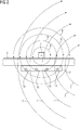
- Fig. 2 represents, based on Fig. 1 , the case that the magnetic field 6 generated by the current flow is superimposed on an external inhomogeneous magnetic field 7, which is, for example, the earth's magnetic field or the magnetic field of a permanent magnet or which is caused by a further current-carrying line, not shown. Since the inhomogeneity of the external magnetic field 7, which is superimposed on the magnetic field 6 to be measured, ie the useful signal, is unknown, as is the case in practice, it is impossible to determine the strength of the magnetic field 6 to be measured alone. A correct indication of the strength of the electric current flowing in the electric line 5 is therefore not possible.
- an external inhomogeneous magnetic field 7 which is, for example, the earth's magnetic field or the magnetic field of a permanent magnet or which is caused by a further current-carrying line, not shown. Since the inhomogeneity of the external magnetic field 7, which is superimposed on the magnetic field 6 to be measured, ie the useful signal, is unknown, as is the case in practice
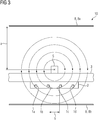
- Fig. 3 based on Fig. 1 , represents a measuring arrangement according to the invention.
- the illustrated measuring arrangement according to the invention has a filter unit 8 for homogenizing magnetic fields not caused by the electric current in the electric line 5 at the location of the magnetic field sensors 1a, 1b, 1c, 1d.
- the filter unit 8 is formed by two plate-shaped filter elements 8a and 8b, between which the electrical line 5 and the magnetic field sensors 1a, 1b, 1c, 1d are arranged.
- One of the filter elements 8a is at a distance a from the electrical line 5.
- Two adjacent magnetic field sensors 1b, 1c are at a distance b from one another, the distance a being greater than the distance b.
- Fig. 4 represents, based on Fig. 3 , represents the case that the magnetic field 6 generated by the current flow is superimposed by an external inhomogeneous magnetic field 7, which z. B. the earth's magnetic field or the magnetic field of a permanent magnet or which is caused by a further current-carrying line, not shown. Due to the filter unit, the external magnetic field 7 between the two plate-shaped filter elements 8 has homogeneous, ie parallel magnetic field lines 9 of the same magnetic field strength, ie the external magnetic field 7 is homogenized between the two plate-shaped filter elements 8.
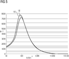
- Fig. 5 shows in an H- ⁇ r diagram with the magnetic field strength H in the unit A / m along the x-axis and the dimensionless permeability number ⁇ r along the y-axis, the curves 16, 18 of permeability numbers ⁇ r as a function of the magnetic field strength H for two exemplary ferromagnetic materials suitable for plate-shaped filter elements, namely the course 16 of the permeability number ⁇ r for the electrical sheet M 330-50 A and the curve 18 of the permeability number ⁇ r for the electrical sheet M 530-50 A, each with a sheet thickness of 0.50 mm.
- the course of the permeability number ⁇ r is roughly the same for both materials: up to a magnetic field strength H in the range of 80 or 100 A / m, the permeability number increases, reaches a maximum at 80 or 100 A / m, and decreases steadily from there from.
- the two materials were chosen because at a magnetic field strength H of 1000 A / m they still have a permeability number ⁇ r > 1000.
- Both types of electrical steel are only to be understood as examples of suitable materials and not restrictive; other ferromagnetic materials can also be used to manufacture the filter elements.
- Fig. 6 is a section through a further embodiment of a measuring arrangement according to the invention.
- a printed circuit board 3 Arranged internally in a printed circuit board 3 is a straight electrical line 5 with a square cross section, along the longitudinal axis of which an electrical current flows, caused by a voltage difference applied to the electrical line 5.
- the technical current direction ie from the electrical positive to the negative pole, is in the plane of the drawing so that the direction of rotation of the field lines 6 of the magnetic field generated by the current flow is clockwise according to the corkscrew rule.
- a current measuring module 2 is arranged on a surface 32 of the printed circuit board 3 and has four Hall sensors 1 a to 1 d arranged in a row across the electrical line 5 as magnetic field sensors. These Hall sensors 1a to 1d detect the Hall voltage U H occurring in the Hall sensor, which is proportional to the field strength of the magnetic field and thus proportional to the conductor current, and send the voltage values via a signal line 14 to a processing unit 12, where the strength of the in the electric current flowing in the electric line 5 is calculated.
- the measuring arrangement 10 has a filter unit 8 for homogenizing magnetic fields, which are not caused by the electric current in the electric line 5, at the location of the magnetic field sensors 1a, 1b, 1c, 1d.
- the filter unit 8 comprises two plate-shaped filter elements 8a and 8b, which are arranged on opposite sides of the electrical line 5 and the magnetic field sensors 1a, 1b, 1c, 1d.
- a first filter element 8a is held in position at a distance a from the electrical line 5 by a first support element 22, which is supported on the printed circuit board 3 and is fastened to the printed circuit board 3.
- a second filter element 8b is held in position by a second support element 20, which is connected to the first support element 22, at a distance a from the electrical line 5.
- the two filter elements 8a, 8b are arranged in a fixed, defined position relative to one another and relative to the printed circuit board 3, and thus also in relation to the electrical line 5 and the current measuring module 2.
- FIGS 7 to 9 illustrate the homogenizing effect of the filter unit under the aspect of the magnetic field strength broken down into subcomponents.
- Fig. 7 shows a magnetic field 6 to be measured, which is caused by a line 5 through which current flows.
- the on Hall sensors arranged in positions 1b and 1c are aligned in such a way that they measure the magnetic field strength of the magnetic field 6 indicated by H only in a transverse direction indicated by ⁇ .
- the Hall sensor arranged at a first position 1b measures only the transverse component H b ⁇ of the magnetic field strength H b present at the first position 1 b , while the parallel component H b does not contribute to the signal of the Hall sensor.
- the Hall sensor arranged at a second position 1c measures only the transverse component H c ⁇ of the magnetic field strength H c present at the second position 1c, while the parallel component H c ⁇ does not contribute to the signal of the Hall sensor. It should be noted that due to the symmetrical positioning of the two Hall sensors, the first cross-component b H ⁇ and the second transverse component having in relation to the electrical current carrying line 5 H c ⁇ different signs.
- Fig. 8 shows an external inhomogeneous magnetic field 7, which is not caused by the current-carrying line 5, but, for example, by a permanent magnet.
- the Hall sensors arranged at positions 1b and 1c are aligned in such a way that they measure the magnetic field strength of the magnetic field 7 indicated by G only in a transverse direction indicated by ⁇ .
- the Hall sensor arranged at a first position 1b measures only the transverse component G b ⁇ of the magnetic field strength G b present at the first position 1 b , while the parallel component G b ⁇ does not contribute to the signal of the Hall sensor.
- the Hall sensor arranged at a second position 1c measures only the transverse component G c ⁇ of the magnetic field strength G c present at the second position 1 c , which due to the course of the magnetic field 7 is identical to the magnetic field strength G c .
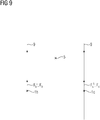
- Fig. 9 shows an external homogenized magnetic field 9, which is generated by a filter unit from the in Fig. 8 shown inhomogeneous magnetic field 7 was created.
- the Hall sensors arranged at positions 1b and 1c are aligned in such a way that they achieve the magnetic field strength of the indicated by F Measure the magnetic field 9 only in a transverse direction indicated by ⁇ .
- the Hall sensor arranged at a first position 1b measures only the transverse component F b ⁇ of the magnetic field strength F b present at the first position 1 b , which due to the course of the magnetic field 9 is identical to the magnetic field strength F b .
- the Hall sensor arranged at a second position 1c measures only the transverse component F c ⁇ of the magnetic field strength F c present at the second position 1 c , which due to the course of the magnetic field 9 is identical to the magnetic field strength F c .
Landscapes
- Physics & Mathematics (AREA)
- General Physics & Mathematics (AREA)
- Measuring Instrument Details And Bridges, And Automatic Balancing Devices (AREA)
Priority Applications (6)
| Application Number | Priority Date | Filing Date | Title |
|---|---|---|---|
| EP19174895.3A EP3739345A1 (fr) | 2019-05-16 | 2019-05-16 | Détection d'un courant électrique circulant dans une conduite électrique |
| PCT/EP2020/062806 WO2020229326A1 (fr) | 2019-05-16 | 2020-05-08 | Dispositif de mesure pour détecter un courant continu |
| US17/611,721 US12013418B2 (en) | 2019-05-16 | 2020-05-08 | Measuring assembly for detecting a direct current |
| DE112020002405.9T DE112020002405A5 (de) | 2019-05-16 | 2020-05-08 | Messanordnung zum Erfassen eines Gleichstroms |
| EP20728950.5A EP3948310A1 (fr) | 2019-05-16 | 2020-05-08 | Dispositif de mesure pour détecter un courant continu |
| CN202080044039.7A CN113994219B (zh) | 2019-05-16 | 2020-05-08 | 用于采集直流电流的测量装置 |
Applications Claiming Priority (1)
| Application Number | Priority Date | Filing Date | Title |
|---|---|---|---|
| EP19174895.3A EP3739345A1 (fr) | 2019-05-16 | 2019-05-16 | Détection d'un courant électrique circulant dans une conduite électrique |
Publications (1)
| Publication Number | Publication Date |
|---|---|
| EP3739345A1 true EP3739345A1 (fr) | 2020-11-18 |
Family
ID=66597514
Family Applications (2)
| Application Number | Title | Priority Date | Filing Date |
|---|---|---|---|
| EP19174895.3A Withdrawn EP3739345A1 (fr) | 2019-05-16 | 2019-05-16 | Détection d'un courant électrique circulant dans une conduite électrique |
| EP20728950.5A Pending EP3948310A1 (fr) | 2019-05-16 | 2020-05-08 | Dispositif de mesure pour détecter un courant continu |
Family Applications After (1)
| Application Number | Title | Priority Date | Filing Date |
|---|---|---|---|
| EP20728950.5A Pending EP3948310A1 (fr) | 2019-05-16 | 2020-05-08 | Dispositif de mesure pour détecter un courant continu |
Country Status (5)
| Country | Link |
|---|---|
| US (1) | US12013418B2 (fr) |
| EP (2) | EP3739345A1 (fr) |
| CN (1) | CN113994219B (fr) |
| DE (1) | DE112020002405A5 (fr) |
| WO (1) | WO2020229326A1 (fr) |
Families Citing this family (5)
| Publication number | Priority date | Publication date | Assignee | Title |
|---|---|---|---|---|
| EP4249924B1 (fr) * | 2022-03-23 | 2025-05-14 | Melexis Technologies SA | Système de capteur de courant |
| DE102023108272A1 (de) | 2023-03-31 | 2024-10-02 | Phoenix Contact Gmbh & Co. Kg | Verfahren und Mess-Anordnung zur Messung der Stromstärke eines durch einen Leiter fließenden elektrischen Stroms |
| LU503820B1 (de) | 2023-03-31 | 2024-09-30 | Phoenix Contact Gmbh & Co | Messgerät zur kontaktlosen Strommessung und Verfahren zu dessen Kalibrierung |
| DE102023108308A1 (de) | 2023-03-31 | 2024-10-02 | Phoenix Contact Gmbh & Co. Kg | Messgerät zur kontaktlosen Strommessung und Verfahren zu dessen Kalibrierung |
| LU503815B1 (de) * | 2023-03-31 | 2024-09-30 | Phoenix Contact Gmbh & Co | Verfahren und Mess-Anordnung zur Messung der Stromstärke eines durch einen Leiter fließenden elektrischen Stroms |
Citations (5)
| Publication number | Priority date | Publication date | Assignee | Title |
|---|---|---|---|---|
| DE20017512U1 (de) * | 2000-10-11 | 2001-02-08 | Honeywell Ag, 63067 Offenbach | Einrichtung zum Messen von Strom auf Leiterplatten |
| WO2008030129A2 (fr) * | 2006-09-06 | 2008-03-13 | Radivoje Popovic | Capteur permettant de mesurer le courant dans une barre omnibus avec correction de l'effet pelliculaire et procédé associé |
| DE102010043254A1 (de) | 2010-11-03 | 2012-05-03 | Siemens Aktiengesellschaft | Messsystem zur Überwachung mindestens einer Phase eines Systems |
| US20150084617A1 (en) * | 2013-09-02 | 2015-03-26 | Senis Ag | Current Transducer For Measuring An Electrical Current |
| DE112015000490T5 (de) * | 2014-01-23 | 2016-11-10 | Denso Corporation | Stromerfassungssystem |
Family Cites Families (11)
| Publication number | Priority date | Publication date | Assignee | Title |
|---|---|---|---|---|
| JP2000258464A (ja) * | 1999-03-09 | 2000-09-22 | Mitsubishi Materials Corp | 電流センサ |
| US7164263B2 (en) * | 2004-01-16 | 2007-01-16 | Fieldmetrics, Inc. | Current sensor |
| DE102007025505A1 (de) | 2007-06-01 | 2008-12-04 | Epcos Ag | Anordnung zur Messung eines in einem elektrischen Leiter fließenden Stroms |
| US20110121827A1 (en) * | 2007-08-06 | 2011-05-26 | Christopher Paul Yakymyshyn | Slotted current transducer using magnetic field point sensors |
| DE102009029209A1 (de) | 2009-09-04 | 2011-03-10 | Robert Bosch Gmbh | Stromsensor, Strommessmodul und Verfahren zur Strommessung |
| JP2011164019A (ja) * | 2010-02-12 | 2011-08-25 | Alps Green Devices Co Ltd | 電流測定装置 |
| US8400139B2 (en) * | 2010-03-26 | 2013-03-19 | Infineon Technologies Ag | Sensor package having a sensor chip |
| US9063184B2 (en) * | 2011-02-09 | 2015-06-23 | International Business Machines Corporation | Non-contact current-sensing and voltage-sensing clamp |
| DE102012012759A1 (de) | 2012-06-27 | 2014-01-02 | Sensitec Gmbh | Anordnung zur Strommessung |
| DE102016210970A1 (de) | 2016-06-20 | 2017-12-21 | Siemens Aktiengesellschaft | Vorrichtung und Verfahren zur Messung der Stromstärke eines einzelnen Leiters eines Mehrleitersystems |
| EP3376238A1 (fr) | 2017-03-16 | 2018-09-19 | LEM Intellectual Property SA | Transducteur de courant électrique avec capteur de gradient de champ magnétique |
-
2019
- 2019-05-16 EP EP19174895.3A patent/EP3739345A1/fr not_active Withdrawn
-
2020
- 2020-05-08 WO PCT/EP2020/062806 patent/WO2020229326A1/fr not_active Ceased
- 2020-05-08 EP EP20728950.5A patent/EP3948310A1/fr active Pending
- 2020-05-08 US US17/611,721 patent/US12013418B2/en active Active
- 2020-05-08 CN CN202080044039.7A patent/CN113994219B/zh active Active
- 2020-05-08 DE DE112020002405.9T patent/DE112020002405A5/de active Pending
Patent Citations (5)
| Publication number | Priority date | Publication date | Assignee | Title |
|---|---|---|---|---|
| DE20017512U1 (de) * | 2000-10-11 | 2001-02-08 | Honeywell Ag, 63067 Offenbach | Einrichtung zum Messen von Strom auf Leiterplatten |
| WO2008030129A2 (fr) * | 2006-09-06 | 2008-03-13 | Radivoje Popovic | Capteur permettant de mesurer le courant dans une barre omnibus avec correction de l'effet pelliculaire et procédé associé |
| DE102010043254A1 (de) | 2010-11-03 | 2012-05-03 | Siemens Aktiengesellschaft | Messsystem zur Überwachung mindestens einer Phase eines Systems |
| US20150084617A1 (en) * | 2013-09-02 | 2015-03-26 | Senis Ag | Current Transducer For Measuring An Electrical Current |
| DE112015000490T5 (de) * | 2014-01-23 | 2016-11-10 | Denso Corporation | Stromerfassungssystem |
Also Published As
| Publication number | Publication date |
|---|---|
| EP3948310A1 (fr) | 2022-02-09 |
| US12013418B2 (en) | 2024-06-18 |
| DE112020002405A5 (de) | 2022-01-27 |
| US20230349955A1 (en) | 2023-11-02 |
| CN113994219B (zh) | 2024-11-22 |
| CN113994219A (zh) | 2022-01-28 |
| WO2020229326A1 (fr) | 2020-11-19 |
Similar Documents
| Publication | Publication Date | Title |
|---|---|---|
| WO2020229326A1 (fr) | Dispositif de mesure pour détecter un courant continu | |
| DE10041599B4 (de) | Stromsensor und elektrischer Schaltkreis, der diesen benutzt | |
| EP1166131A1 (fr) | Mesureur de courant | |
| EP1772737A2 (fr) | Module pour mesurer un courant | |
| DE102020122262A1 (de) | Stromsensor | |
| DE4020228A1 (de) | Anordnung zum detektieren eines bewegten ferromagnetischen elements | |
| EP1352254A2 (fr) | Dispositif, amperemetre et vehicule motorise | |
| DE112018000561T5 (de) | Element-einheit mit magnetoresistivem effekt und vorrichtung mit element-einheit mit magnetoresistivem effekt | |
| DE102021110370A1 (de) | Stromsensor | |
| DE102019109225A1 (de) | PCBA mit Punktfelddetektor und magnetischer Abschirmungsanordnung, die sich auf der gleichen Seite eines Leiters befindet | |
| DE10107811A1 (de) | Vorrichtung, Strommesser und Kraftfahrzeug | |
| EP2174147B1 (fr) | Dispositif de mesure d'un courant circulant dans un conducteur électrique | |
| DE102010036040A1 (de) | Strommesseinrichtung, insbesondere in einem Umrichter eines Flurförderzeugs | |
| DE102005028572B4 (de) | Stromsensoranordung mit einem Magnetkern | |
| EP3593152B1 (fr) | Connecteur modulaire avec agencement de capteurs de courant et procédé de mesure de courant | |
| DE102020100635A1 (de) | Hochvolt-Anschlussmodul und Stromrichter | |
| DE202013010178U1 (de) | Stromerfassungsvorrichtung | |
| AT510380B1 (de) | Vorrichtung zur strommessung bei leistungskondensatoren | |
| DE10107812B4 (de) | Vorrichtung zur Messung der elektrischen Stromstärke | |
| EP2116855B1 (fr) | Dispositif de mesure de courant | |
| DE102017218737A1 (de) | Stromerfassungseinrichtung mit orthogonal zueinander ausgerichteten Messbereichen | |
| DE102020117557B4 (de) | Stromsensor zur Messung des elektrischen Stroms einer Stromschiene | |
| EP4139696B1 (fr) | Unité capteur de courant | |
| EP3734298B1 (fr) | Dispositif de mesure permettant de détecter un courant électrique | |
| DE102019115339B4 (de) | Sensorvorrichtung zur Messung von Wechselströmen mit einem verbesserten Schließmechanismus |
Legal Events
| Date | Code | Title | Description |
|---|---|---|---|
| PUAI | Public reference made under article 153(3) epc to a published international application that has entered the european phase |
Free format text: ORIGINAL CODE: 0009012 |
|
| STAA | Information on the status of an ep patent application or granted ep patent |
Free format text: STATUS: THE APPLICATION HAS BEEN PUBLISHED |
|
| AK | Designated contracting states |
Kind code of ref document: A1 Designated state(s): AL AT BE BG CH CY CZ DE DK EE ES FI FR GB GR HR HU IE IS IT LI LT LU LV MC MK MT NL NO PL PT RO RS SE SI SK SM TR |
|
| AX | Request for extension of the european patent |
Extension state: BA ME |
|
| STAA | Information on the status of an ep patent application or granted ep patent |
Free format text: STATUS: THE APPLICATION IS DEEMED TO BE WITHDRAWN |
|
| 18D | Application deemed to be withdrawn |
Effective date: 20210519 |