EP3739348A1 - Procédé de diagnostic d'appareillage de commutation et dispositif associé - Google Patents
Procédé de diagnostic d'appareillage de commutation et dispositif associé Download PDFInfo
- Publication number
- EP3739348A1 EP3739348A1 EP20171369.0A EP20171369A EP3739348A1 EP 3739348 A1 EP3739348 A1 EP 3739348A1 EP 20171369 A EP20171369 A EP 20171369A EP 3739348 A1 EP3739348 A1 EP 3739348A1
- Authority
- EP
- European Patent Office
- Prior art keywords
- switchgear
- frequency
- diagnosis
- learning data
- feature values
- Prior art date
- Legal status (The legal status is an assumption and is not a legal conclusion. Google has not performed a legal analysis and makes no representation as to the accuracy of the status listed.)
- Withdrawn
Links
Images


Classifications
-
- G—PHYSICS
- G01—MEASURING; TESTING
- G01R—MEASURING ELECTRIC VARIABLES; MEASURING MAGNETIC VARIABLES
- G01R31/00—Arrangements for testing electric properties; Arrangements for locating electric faults; Arrangements for electrical testing characterised by what is being tested not provided for elsewhere
- G01R31/327—Testing of circuit interrupters, switches or circuit-breakers
- G01R31/3271—Testing of circuit interrupters, switches or circuit-breakers of high voltage or medium voltage devices
- G01R31/3275—Fault detection or status indication
-
- G—PHYSICS
- G01—MEASURING; TESTING
- G01H—MEASUREMENT OF MECHANICAL VIBRATIONS OR ULTRASONIC, SONIC OR INFRASONIC WAVES
- G01H17/00—Measuring mechanical vibrations or ultrasonic, sonic or infrasonic waves, not provided for in the other groups of this subclass
-
- G—PHYSICS
- G01—MEASURING; TESTING
- G01R—MEASURING ELECTRIC VARIABLES; MEASURING MAGNETIC VARIABLES
- G01R31/00—Arrangements for testing electric properties; Arrangements for locating electric faults; Arrangements for electrical testing characterised by what is being tested not provided for elsewhere
- G01R31/327—Testing of circuit interrupters, switches or circuit-breakers
-
- G—PHYSICS
- G01—MEASURING; TESTING
- G01R—MEASURING ELECTRIC VARIABLES; MEASURING MAGNETIC VARIABLES
- G01R31/00—Arrangements for testing electric properties; Arrangements for locating electric faults; Arrangements for electrical testing characterised by what is being tested not provided for elsewhere
- G01R31/327—Testing of circuit interrupters, switches or circuit-breakers
- G01R31/3271—Testing of circuit interrupters, switches or circuit-breakers of high voltage or medium voltage devices
- G01R31/3272—Apparatus, systems or circuits therefor
- G01R31/3274—Details related to measuring, e.g. sensing, displaying or computing; Measuring of variables related to the contact pieces, e.g. wear, position or resistance
-
- G—PHYSICS
- G01—MEASURING; TESTING
- G01P—MEASURING LINEAR OR ANGULAR SPEED, ACCELERATION, DECELERATION, OR SHOCK; INDICATING PRESENCE, ABSENCE, OR DIRECTION, OF MOVEMENT
- G01P15/00—Measuring acceleration; Measuring deceleration; Measuring shock, i.e. sudden change of acceleration
Definitions
- the present invention relates to a diagnostic method of switchgear and a device thereof that diagnose a state of a switchgear.
- a switchgear has an important role of cutting off an accident current to protect a device of a load. Once the switchgear breaks down, an influence due to a power failure is large, and its repair takes time.
- an acceleration sensor is mounted to a breaker to measure a vibration waveform at the time of switching, calculate a coefficient of correlation with an initial vibration waveform, and evaluate a state of the breaker.
- Patent Literature 2 an acceleration sensor and a vibration exciter are mounted to a breaker and a casing of the breaker is vibrated by the vibration exciter to measure a vibration waveform and evaluate a difference from a resonance point of the spectrum in normal to detect looseness of a bolt, which becomes a cause of a damage accident.
- Patent Literature 1 to obtain the vibration waveform, a switching operation of the breaker needs to be waited. Therefore, with a breaker of low switching frequency, a frequency that the state can be diagnosed is low and therefore regularly grasping the state has been difficult.
- Patent Literature 2 mounting the vibration exciter to the breaker is also necessary to obtain the vibration waveform, thereby having a problem in reliability.
- an object of the present invention is to provide a diagnostic method of switchgear and a device thereof that allow regularly grasping a state with high accuracy with a simple configuration.
- a diagnostic method of switchgear includes: obtaining signals from an acceleration sensor mounted to a switchgear and a load current flowing through the switchgear; determining a frequency to be focused from a spectrum analysis result of the signals from the acceleration sensor in an advance preparation phase of diagnosis of the switchgear, generating learning data using at least the frequency and the load current as feature values; and regularly diagnosing a state of the switchgear from the feature values obtained during diagnosis and the learning data during the diagnosis of the switchgear.
- a diagnostic device of switchgear includes an input unit, a learning data database, and a state estimator.
- the input unit is configured to obtain signals from an acceleration sensor mounted to a switchgear and a load current flowing through the switchgear.
- the learning data database is configured to store learning data.
- the learning data is generated by determining a frequency to be focused from a spectrum analysis result of the signals from the acceleration sensor in an advance preparation phase of diagnosis of the switchgear and using at least the frequency and the load current as feature values.
- the state estimator is configured to regularly diagnose a state of the switchgear from the feature values obtained during diagnosis and the learning data during the diagnosis of the switchgear.
- a diagnostic method of switchgear and a device thereof that allow regularly grasping a state with high accuracy with a simple configuration can be provided.
- the present invention features that a state of a switchgear, that is, presence/absence of abnormality is estimated with high accuracy without a wait for switching operation.
- Fig. 1 illustrates a basic configuration example of a diagnostic device of switchgear according to the embodiment of the present invention.
- the diagnostic device of the present invention includes an acceleration sensor 10 mounted to a switchgear 1 as a diagnostic target, a state estimator 5, and a learning data database 6.
- a plurality of the acceleration sensors 10 may be mounted.
- a current I (load current) fed to the switchgear 1 and a voltage V (applied voltage) are input to the state estimator 5.
- Fig. 2 illustrates another basic configuration example of the diagnostic device of switchgear according to the embodiment of the present invention.
- information on the voltage V (applied voltage) input to the state estimator 5 is usually maintained to be constant. Accordingly, its magnitude is of small importance. If anything, since it is only necessary that whether the voltage is applied or not can be determined, the information is substitution for switching information S on a switch contact point.
- Fig. 3 illustrates an example of the switchgear 1 to which the present invention is applied.
- a power supply-side breaker 1e and a load-side breaker 1d of a transformer coupled to a bus bar in an electrical substation are targets for application.
- further breakers 1a, 1b, and 1c of power-transmission lines branched from the bus bar of the electrical substation, and the like are targets for application.
- various disconnectors can be application targets of the present invention.
- the state estimator 5 calculates a degree of match with the input based on learning with learning data stored in a learning data database 6 representative of the input state in normal and notifies (result notification) the evaluation result equivalent to an amount of deviation from the normal state.
- the smaller evaluation result means that the input matches the pattern in normal, and the larger evaluation result means that a degree of deterioration increases.
- Fig. 4 is a drawing illustrating a relationship between the load current (horizontal axis) and the magnitude of the acceleration (vertical axis) and illustrates a result of actually measuring the magnitude of the acceleration relative to the load current.
- the magnitude of the acceleration increases by a square of the load current.
- the acceleration at the load current of 0 (A) is considered to be a sum of a noise component and the electrostatic force generated by voltage. That is, the magnitude of the acceleration depends on the current I and the voltage V. Based on the knowledge, considering the magnitudes of the current I and the voltage V, states in normal and in abnormality are highly sensitively identifiable from the acceleration vibration waveform that is regularly measured.
- the switchgear 1 can be determined as abnormal.
- a state in which the measured acceleration has a value departed from a threshold is continuously observed sometimes due to progress of deterioration with, for example, progress of an operating period of the switchgear 1 progresses.
- the value is usually in a predetermined range according to the current I.
- Fig. 5 and Fig. 6 are drawings illustrating an example of determining abnormality from a secular change (horizontal axis) in an evaluation result (vertical axis) of the magnitude of observed acceleration.
- Fig. 5 and Fig. 6 illustrate an example of a screen that displays trend data based on a notification result given by the state estimator 5.
- the evaluation result by analysis is sequentially plotted to be time-oriented and determined as abnormal when a predetermined threshold is exceeded.
- a rate of change in the trend of the evaluation result is monitored.
- this state is recognized as an abnormal preliminary state, and time intersecting with the threshold is roughly estimated by prediction and time when abnormality occurs is estimated, thus ensuring scheduled inspection.
- abnormality such as seizing, looseness of a bolt, and insufficient contact pressure, which have been conventionally overlooked, can be found by taking measures when the evaluation value or its changing rate exceeds a predetermined value or a predetermined range. Therefore, these methods are useful to avoid an accident in advance.
- a further specific evaluation method using multivariate analysis method (for example, the Mahalanobis-Taguchi method and VQC) will be described as the internal process in the state estimator 5 based on the flowchart.
- the internal process in the state estimator 5 is divided into a process in an advance preparation phase before diagnosis and a process in a diagnostic phase where various kinds of data are prepared and diagnosis is performed and executed.
- Fig. 7 illustrates the processes in the advance preparation phase before diagnosis.
- the advance preparation phase before diagnosis generates the learning data database 6 in Fig. 1 .
- the process here are processes of two phases, which are a process of determining feature values (process step S1) and a process of generating the learning data (process step S2) .
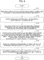
- Fig. 8 depicts the detailed flowchart of the process step S1, which is the process of determining the feature values.
- step S11 which is the first process of determining the feature values (process step S1) depicted in Fig. 8 .
- Nn pieces of the acceleration waveforms in normal and Na pieces of the acceleration waveforms in abnormality are measured by the acceleration sensor 10 mounted to the switchgear 1.
- the acceleration waveform when a switchgear for simulation is purposely operated as an abnormal state may be used as the acceleration waveform in abnormality, or the acceleration waveform in abnormality may be prepared from the already known information.
- a process step S12 frequency spectra of all of the acceleration waveforms (Nn + Na pieces) are derived by FFT. As a result, a spectrum value for each discrete frequency is determined in each waveform of the acceleration waveforms (Nn + Na pieces). Note that it is conceivable that the spectrum waveform itself is used as the feature value. However, to obtain identification performance between abnormality and normal, a part related to state diagnosis needs to be extracted.
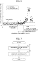
- Fig. 9 illustrates an example of results of frequency spectrum analysis of Nn pieces of the acceleration waveforms in normal and Na pieces of the acceleration waveforms in abnormality.
- Fig. 9 plotting a frequency on the horizontal axis and a spectrum value on the vertical axis, while an analysis result of Nn pieces of the acceleration waveforms in normal exhibits a tendency like N, the analysis result of Na pieces of the acceleration waveforms in abnormality exhibits a tendency like A.
- the two waveforms exhibit a large difference at a frequency f of f 1 and f 2 , by grasping and monitoring the magnitudes at the frequencies f 1 and f 2 as the feature values, abnormality and normal are identifiable. Performing the following processes allows achieving the identification process.
- mean values Mn(f) and standard deviations on(f) of a spectrum of the frequency f for Nn pieces of acceleration waveform groups in normal are calculated.
- mean values Mn(f) and standard deviations on(f) of a spectrum of the frequency f for Na pieces of acceleration waveform groups in abnormality are calculated.
- an evaluation formula g(f) that becomes large when a difference in average between in normal and in abnormality
- is large and becomes small when the standard deviations ⁇ n (f) and ⁇ a(f) are large is generated. It is conceivable that, for sensitive identification between abnormality and normal, the larger the difference in average is, the easier the identification is, and when the difference is small, the difference does not contribute to the identification. To reduce false detection, one with low variation is preferably employed. As the evaluation formula g(f), for example, the following Equation (1) is preferably employed. [Math. 1] g f Mn f ⁇ Ma f / ⁇ ⁇ n f ⁇ a f
- N-2 pieces of the frequencies f at which the value of the evaluation formula g(f) increases is selected, and each of them is defined as f(1), f(2),..., f(N-2).
- the current I, the voltage V, and spectrum values Sp(1),..., Sp(N-2) corresponding to the frequencies f(1), f(2),..., f(N-2) are determined as the feature values. This allows extracting one set of feature values from measurement data at certain time. As described above, the process of Fig. 8 allows determining the feature values.
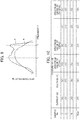
- the feature values constituting the learning data illustrated in Fig. 10 are a collection of a plurality of samples of spectrum values at the respective frequencies (f(1), f(2),..., f(N-2)) according to each combination of magnitudes of voltages and currents.
- the learning data is generated by obtaining Nsm pieces (> N) of data in normal and extracting Nsm sets of feature values determined in the process step S1 of Fig. 7 .
- This learning data a large number of various conditions that probably occur in normal are preferably obtained.
- I denotes an effective value of current (A)
- t denotes time (s) .
- an acceleration a u of the conductor u and an acceleration a w of the conductor w are expressed by Equations (3) and (4), respectively.
- the accelerations of the conductors from the accelerations a w and a u are proportionate to a square of an effective value of the current in a horizontal direction. Additionally, the accelerations are periodic to ⁇ t at a cycle ⁇ . That is, it is seen that the vibration occurs at a frequency twice a fundamental frequency.
- a device coupled to a commercial frequency of 50 Hz is vibrated at 100 Hz and a device coupled to the commercial frequency of 60 Hz is vibrated at 120 Hz by electromagnetic force.
- selecting a harmonic to the commercial frequency as a monitoring target frequency is effective.
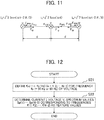
- Fig. 12 depicts a detailed procedure for another method of determining the feature value.
- the current I, the voltage V, and the spectrum values Sp(1),..., Sp(N-2) corresponding to the frequencies f(1), f(2),..., f(N-2) are determined as feature values.
- This method is effective in a case where data in abnormality cannot be obtained and is a simple method.
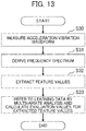
- Fig. 13 depicts processes in the diagnostic phase.
- a process step S30 the acceleration vibration waveform is measured, subsequently its frequency spectrum is derived in a process step S31, and subsequently the above-described feature values are extracted in a process step S32.
- the feature values are collated with the learning data illustrated in Fig. 10 by multivariate analysis method, such as the Mahalanobis-Taguchi method and VQC, and evaluation values for the extracted feature values are calculated.
- the above-described method allows the regular evaluation of the state of the switchgear.
- Fig. 6 described above illustrates the example of the results when the abnormality is simulated for experiment in the embodiment of the present invention, and therefore the identification results will be described with reference to the drawing. Note that, in Fig. 6 , the white circles indicate the evaluation results in normal and the black circles indicate the evaluation results in abnormality.
- a method for determining the threshold to eliminate the false detection as many as possible includes, for example, the use of a straight line passing through the maximum evaluation value of the data measured in normal as the threshold, or the use of, for example, "mean value + 3 ⁇ standard deviation" as the threshold using a mean value and a standard deviation of the evaluation values in normal.
Landscapes
- Physics & Mathematics (AREA)
- General Physics & Mathematics (AREA)
- Engineering & Computer Science (AREA)
- Theoretical Computer Science (AREA)
- Arc-Extinguishing Devices That Are Switches (AREA)
- Testing Of Devices, Machine Parts, Or Other Structures Thereof (AREA)
- Gas-Insulated Switchgears (AREA)
Applications Claiming Priority (1)
| Application Number | Priority Date | Filing Date | Title |
|---|---|---|---|
| JP2019092765A JP7227846B2 (ja) | 2019-05-16 | 2019-05-16 | 開閉装置の診断方法及び装置 |
Publications (1)
| Publication Number | Publication Date |
|---|---|
| EP3739348A1 true EP3739348A1 (fr) | 2020-11-18 |
Family
ID=70464894
Family Applications (1)
| Application Number | Title | Priority Date | Filing Date |
|---|---|---|---|
| EP20171369.0A Withdrawn EP3739348A1 (fr) | 2019-05-16 | 2020-04-24 | Procédé de diagnostic d'appareillage de commutation et dispositif associé |
Country Status (4)
| Country | Link |
|---|---|
| US (1) | US11249137B2 (fr) |
| EP (1) | EP3739348A1 (fr) |
| JP (1) | JP7227846B2 (fr) |
| CN (1) | CN111948528B (fr) |
Cited By (1)
| Publication number | Priority date | Publication date | Assignee | Title |
|---|---|---|---|---|
| CN117607679A (zh) * | 2024-01-23 | 2024-02-27 | 东莞市钜欣电子有限公司 | 一种薄膜开关的性能检测方法、系统、处理器和存储介质 |
Families Citing this family (3)
| Publication number | Priority date | Publication date | Assignee | Title |
|---|---|---|---|---|
| CN113503289A (zh) * | 2021-07-29 | 2021-10-15 | 杭州力龙液压有限公司 | 一种液压马达故障检测方法、装置、系统及挖掘机 |
| EP4163616B1 (fr) * | 2021-10-06 | 2025-08-20 | Hitachi Energy Ltd | Surveillance de dispositif de puissance |
| CN121388955B (zh) * | 2025-12-25 | 2026-04-07 | 浙江华采科技有限公司 | 一种高压开关操作机构故障预测方法及系统 |
Citations (9)
| Publication number | Priority date | Publication date | Assignee | Title |
|---|---|---|---|---|
| JP2002367492A (ja) | 2001-06-07 | 2002-12-20 | Hitachi Engineering & Services Co Ltd | 遮断器のボルトの緩み診断評価方法および装置 |
| US20100169030A1 (en) * | 2007-05-24 | 2010-07-01 | Alexander George Parlos | Machine condition assessment through power distribution networks |
| JP2011103230A (ja) | 2009-11-11 | 2011-05-26 | Sumitomo Metal Ind Ltd | 開閉器の診断方法及び開閉器の診断装置 |
| CN107450017A (zh) * | 2017-08-04 | 2017-12-08 | 内蒙古电力(集团)有限责任公司包头供电局 | 一种开关设备缺陷智能检测系统 |
| CN207148285U (zh) * | 2017-08-21 | 2018-03-27 | 国网上海市电力公司 | 一种开关设备智能检测终端 |
| KR101865086B1 (ko) * | 2017-11-15 | 2018-06-07 | (주) 동보파워텍 | 사고데이터 분석과 내부 이상상태 감시 및 진단 기능을 구비한 고장감시진단장치 내장형 수배전반 |
| CN108152726A (zh) * | 2017-12-18 | 2018-06-12 | 西安辰耀电气技术有限公司 | 在线监测断路器机械状态的智能电力仪表及高压开关柜 |
| CN105703258B (zh) * | 2016-03-21 | 2019-01-01 | 广东电网有限责任公司东莞供电局 | Gis开关设备动作状态监测系统及其使用方法 |
| CN109425826A (zh) * | 2017-08-21 | 2019-03-05 | 国网上海市电力公司 | 一种开关设备智能检测终端 |
Family Cites Families (14)
| Publication number | Priority date | Publication date | Assignee | Title |
|---|---|---|---|---|
| US4975800A (en) * | 1988-03-14 | 1990-12-04 | Hitachi, Ltd. | Contact abnormality detecting system |
| JPH0690892B2 (ja) * | 1988-03-14 | 1994-11-14 | 株式会社日立製作所 | ガス絶縁開閉機器の通電異常検出装置 |
| JP2997571B2 (ja) * | 1991-07-10 | 2000-01-11 | 三菱電機株式会社 | 監視診断装置 |
| JP3100757B2 (ja) * | 1992-06-02 | 2000-10-23 | 三菱電機株式会社 | 監視診断装置 |
| CN101709995A (zh) * | 2009-12-24 | 2010-05-19 | 浙江大学 | 电力变压器振动在线监测及故障诊断方法 |
| CN202066583U (zh) * | 2011-03-17 | 2011-12-07 | 中国电力科学研究院 | 一种变压器有载分接开关的振动测量系统 |
| CN104181460B (zh) * | 2014-07-07 | 2017-06-06 | 沈阳工业大学 | 一种基于多信息融合的永磁机构真空断路器故障诊断方法 |
| CN105116320B (zh) * | 2015-08-24 | 2018-08-03 | 国家电网公司 | 一种气体绝缘组合电器隔离开关接触状态试验与测试系统 |
| CN105510813A (zh) * | 2015-10-12 | 2016-04-20 | 国家电网公司 | 一种基于振动原理的换流变分接开关状态在线监测系统 |
| CN105548874B (zh) * | 2015-12-31 | 2019-03-01 | 北京四方继保自动化股份有限公司 | 一种智能开关状态综合在线监测与故障诊断装置 |
| CN106643877A (zh) * | 2016-11-18 | 2017-05-10 | 西安亚能电气有限责任公司 | 基于多传感信息融合的电力变压器在线监测系统及方法 |
| CN107356869A (zh) * | 2017-07-31 | 2017-11-17 | 海南电网有限责任公司琼海供电局 | 一种变压器有载调压开关故障诊断系统 |
| CN108445382A (zh) * | 2018-04-23 | 2018-08-24 | 温州大学 | 一种高压断路器的快速失效检测方法 |
| CN109188258A (zh) * | 2018-07-17 | 2019-01-11 | 国网浙江省电力有限公司检修分公司 | 基于振电结合的高压断路器特征提取及分类方法 |
-
2019
- 2019-05-16 JP JP2019092765A patent/JP7227846B2/ja active Active
-
2020
- 2020-04-24 EP EP20171369.0A patent/EP3739348A1/fr not_active Withdrawn
- 2020-05-12 US US16/872,585 patent/US11249137B2/en not_active Expired - Fee Related
- 2020-05-15 CN CN202010410630.1A patent/CN111948528B/zh active Active
Patent Citations (9)
| Publication number | Priority date | Publication date | Assignee | Title |
|---|---|---|---|---|
| JP2002367492A (ja) | 2001-06-07 | 2002-12-20 | Hitachi Engineering & Services Co Ltd | 遮断器のボルトの緩み診断評価方法および装置 |
| US20100169030A1 (en) * | 2007-05-24 | 2010-07-01 | Alexander George Parlos | Machine condition assessment through power distribution networks |
| JP2011103230A (ja) | 2009-11-11 | 2011-05-26 | Sumitomo Metal Ind Ltd | 開閉器の診断方法及び開閉器の診断装置 |
| CN105703258B (zh) * | 2016-03-21 | 2019-01-01 | 广东电网有限责任公司东莞供电局 | Gis开关设备动作状态监测系统及其使用方法 |
| CN107450017A (zh) * | 2017-08-04 | 2017-12-08 | 内蒙古电力(集团)有限责任公司包头供电局 | 一种开关设备缺陷智能检测系统 |
| CN207148285U (zh) * | 2017-08-21 | 2018-03-27 | 国网上海市电力公司 | 一种开关设备智能检测终端 |
| CN109425826A (zh) * | 2017-08-21 | 2019-03-05 | 国网上海市电力公司 | 一种开关设备智能检测终端 |
| KR101865086B1 (ko) * | 2017-11-15 | 2018-06-07 | (주) 동보파워텍 | 사고데이터 분석과 내부 이상상태 감시 및 진단 기능을 구비한 고장감시진단장치 내장형 수배전반 |
| CN108152726A (zh) * | 2017-12-18 | 2018-06-12 | 西安辰耀电气技术有限公司 | 在线监测断路器机械状态的智能电力仪表及高压开关柜 |
Non-Patent Citations (1)
| Title |
|---|
| OGI H ET AL: "Fault Diagnosis Of Gas Insulated Switchgear Using Adaptive Neural Networks", 19930905; 19930905 - 19930908, vol. 1, 5 September 1993 (1993-09-05), pages 49 - 56, XP010278981 * |
Cited By (2)
| Publication number | Priority date | Publication date | Assignee | Title |
|---|---|---|---|---|
| CN117607679A (zh) * | 2024-01-23 | 2024-02-27 | 东莞市钜欣电子有限公司 | 一种薄膜开关的性能检测方法、系统、处理器和存储介质 |
| CN117607679B (zh) * | 2024-01-23 | 2024-04-23 | 东莞市钜欣电子有限公司 | 一种薄膜开关的性能检测方法、系统、处理器和存储介质 |
Also Published As
| Publication number | Publication date |
|---|---|
| CN111948528B (zh) | 2023-04-18 |
| JP7227846B2 (ja) | 2023-02-22 |
| JP2020187955A (ja) | 2020-11-19 |
| US11249137B2 (en) | 2022-02-15 |
| US20200363473A1 (en) | 2020-11-19 |
| CN111948528A (zh) | 2020-11-17 |
Similar Documents
| Publication | Publication Date | Title |
|---|---|---|
| EP3739348A1 (fr) | Procédé de diagnostic d'appareillage de commutation et dispositif associé | |
| KR101874286B1 (ko) | 전력설비 모니터링 및 진단 시스템 | |
| US8095326B2 (en) | Method and device to predict a state of a power system in the time domain | |
| EP3268760B1 (fr) | Dispositif de surveillance de terre neutre de générateur à l'aide d'une mesure et d'une analyse de composantes de courant continu | |
| KR102427372B1 (ko) | 이상 진단 장치, 이상 진단 방법 및 이상 진단 시스템 | |
| EP3648338B1 (fr) | Dispositif de diagnostic de moteur électrique | |
| EP3474029B1 (fr) | Dispositif de détection d'anomalie de charge | |
| EP3579404B1 (fr) | Dispositif de diagnostic de moteur | |
| CN113647013B (zh) | 电动机设备的异常诊断装置、电动机设备的异常诊断方法和电动机设备的异常诊断系统 | |
| WO2014156386A1 (fr) | Dispositif de diagnostic de moteur électrique et dispositif commutateur | |
| EP2082246A2 (fr) | Détection de défaut de câble | |
| CN110689252A (zh) | 一种电容式电压互感器计量误差态势感知系统 | |
| CN116430110A (zh) | 一种电流同步采集方法、系统、终端设备及存储介质 | |
| Bugajska et al. | Impedance-based short circuit—Short circuit fault location method in coaxial cables | |
| KR101413788B1 (ko) | 변압기 이상 진단 방법 및 장치 | |
| Bengtsson et al. | Power transformer performance monitoring presented in SCADA | |
| EP4600682A1 (fr) | Système et procédé mis en oeuvre dans celui-ci | |
| JPH04212076A (ja) | 電気機器の異常診断方法およびその装置 | |
| Sahraoui et al. | An improved algorithm for detection of rotor faults in squirrel cage induction motors based on a new fault indicator | |
| RU2814857C1 (ru) | Система мониторинга и диагностирования состояния турбогенератора | |
| JP2002131367A (ja) | 電気設備の絶縁劣化診断方法 | |
| Stojcic et al. | Detecting incipient stator winding conductor faults in inverter fed machines | |
| KR20230078353A (ko) | 부분방전 측정 시스템 및 이를 위한 동작 방법 |
Legal Events
| Date | Code | Title | Description |
|---|---|---|---|
| PUAI | Public reference made under article 153(3) epc to a published international application that has entered the european phase |
Free format text: ORIGINAL CODE: 0009012 |
|
| STAA | Information on the status of an ep patent application or granted ep patent |
Free format text: STATUS: REQUEST FOR EXAMINATION WAS MADE |
|
| 17P | Request for examination filed |
Effective date: 20200424 |
|
| AK | Designated contracting states |
Kind code of ref document: A1 Designated state(s): AL AT BE BG CH CY CZ DE DK EE ES FI FR GB GR HR HU IE IS IT LI LT LU LV MC MK MT NL NO PL PT RO RS SE SI SK SM TR |
|
| AX | Request for extension of the european patent |
Extension state: BA ME |
|
| GRAP | Despatch of communication of intention to grant a patent |
Free format text: ORIGINAL CODE: EPIDOSNIGR1 |
|
| STAA | Information on the status of an ep patent application or granted ep patent |
Free format text: STATUS: GRANT OF PATENT IS INTENDED |
|
| INTG | Intention to grant announced |
Effective date: 20230127 |
|
| STAA | Information on the status of an ep patent application or granted ep patent |
Free format text: STATUS: THE APPLICATION IS DEEMED TO BE WITHDRAWN |
|
| 18D | Application deemed to be withdrawn |
Effective date: 20230607 |