EP3739403A1 - Verfahren zum betrieb und zur prädiktiven überwachung eines feldgerätes - Google Patents
Verfahren zum betrieb und zur prädiktiven überwachung eines feldgerätes Download PDFInfo
- Publication number
- EP3739403A1 EP3739403A1 EP20168733.2A EP20168733A EP3739403A1 EP 3739403 A1 EP3739403 A1 EP 3739403A1 EP 20168733 A EP20168733 A EP 20168733A EP 3739403 A1 EP3739403 A1 EP 3739403A1
- Authority
- EP
- European Patent Office
- Prior art keywords
- deviations
- deviation
- determined
- field device
- monitoring
- Prior art date
- Legal status (The legal status is an assumption and is not a legal conclusion. Google has not performed a legal analysis and makes no representation as to the accuracy of the status listed.)
- Granted
Links
Images
Classifications
-
- G—PHYSICS
- G05—CONTROLLING; REGULATING
- G05B—CONTROL OR REGULATING SYSTEMS IN GENERAL; FUNCTIONAL ELEMENTS OF SUCH SYSTEMS; MONITORING OR TESTING ARRANGEMENTS FOR SUCH SYSTEMS OR ELEMENTS
- G05B19/00—Program-control systems
- G05B19/02—Program-control systems electric
- G05B19/04—Program control other than numerical control, i.e. in sequence controllers or logic controllers
- G05B19/042—Program control other than numerical control, i.e. in sequence controllers or logic controllers using digital processors
-
- G—PHYSICS
- G01—MEASURING; TESTING
- G01F—MEASURING VOLUME, VOLUME FLOW, MASS FLOW OR LIQUID LEVEL; METERING BY VOLUME
- G01F1/00—Measuring the volume flow or mass flow of fluid or fluent solid material wherein the fluid passes through a meter in a continuous flow
- G01F1/66—Measuring the volume flow or mass flow of fluid or fluent solid material wherein the fluid passes through a meter in a continuous flow by measuring frequency, phase shift or propagation time of electromagnetic or other waves, e.g. using ultrasonic flowmeters
- G01F1/662—Constructional details
-
- G—PHYSICS
- G01—MEASURING; TESTING
- G01D—MEASURING NOT SPECIALLY ADAPTED FOR A SPECIFIC VARIABLE; ARRANGEMENTS FOR MEASURING TWO OR MORE VARIABLES NOT COVERED IN A SINGLE OTHER SUBCLASS; TARIFF METERING APPARATUS; MEASURING OR TESTING NOT OTHERWISE PROVIDED FOR
- G01D1/00—Measuring arrangements giving results other than momentary value of variable, of general application
- G01D1/14—Measuring arrangements giving results other than momentary value of variable, of general application giving a distribution function of a value, i.e. number of times the value comes within specified ranges of amplitude
-
- G—PHYSICS
- G01—MEASURING; TESTING
- G01D—MEASURING NOT SPECIALLY ADAPTED FOR A SPECIFIC VARIABLE; ARRANGEMENTS FOR MEASURING TWO OR MORE VARIABLES NOT COVERED IN A SINGLE OTHER SUBCLASS; TARIFF METERING APPARATUS; MEASURING OR TESTING NOT OTHERWISE PROVIDED FOR
- G01D1/00—Measuring arrangements giving results other than momentary value of variable, of general application
- G01D1/18—Measuring arrangements giving results other than momentary value of variable, of general application with arrangements for signalling that a predetermined value of an unspecified parameter has been exceeded
-
- G—PHYSICS
- G01—MEASURING; TESTING
- G01D—MEASURING NOT SPECIALLY ADAPTED FOR A SPECIFIC VARIABLE; ARRANGEMENTS FOR MEASURING TWO OR MORE VARIABLES NOT COVERED IN A SINGLE OTHER SUBCLASS; TARIFF METERING APPARATUS; MEASURING OR TESTING NOT OTHERWISE PROVIDED FOR
- G01D3/00—Indicating or recording apparatus with provision for the special purposes referred to in the subgroups
- G01D3/08—Indicating or recording apparatus with provision for the special purposes referred to in the subgroups with provision for safeguarding the apparatus, e.g. against abnormal operation, against breakdown
-
- G—PHYSICS
- G01—MEASURING; TESTING
- G01F—MEASURING VOLUME, VOLUME FLOW, MASS FLOW OR LIQUID LEVEL; METERING BY VOLUME
- G01F25/00—Testing or calibration of apparatus for measuring volume, volume flow or liquid level or for metering by volume
- G01F25/10—Testing or calibration of apparatus for measuring volume, volume flow or liquid level or for metering by volume of flowmeters
-
- G—PHYSICS
- G01—MEASURING; TESTING
- G01K—MEASURING TEMPERATURE; MEASURING QUANTITY OF HEAT; THERMALLY-SENSITIVE ELEMENTS NOT OTHERWISE PROVIDED FOR
- G01K13/00—Thermometers specially adapted for specific purposes
-
- G—PHYSICS
- G01—MEASURING; TESTING
- G01K—MEASURING TEMPERATURE; MEASURING QUANTITY OF HEAT; THERMALLY-SENSITIVE ELEMENTS NOT OTHERWISE PROVIDED FOR
- G01K15/00—Testing or calibrating of thermometers
- G01K15/005—Calibration
-
- G—PHYSICS
- G01—MEASURING; TESTING
- G01N—INVESTIGATING OR ANALYSING MATERIALS BY DETERMINING THEIR CHEMICAL OR PHYSICAL PROPERTIES
- G01N27/00—Investigating or analysing materials by the use of electric, electrochemical, or magnetic means
- G01N27/26—Investigating or analysing materials by the use of electric, electrochemical, or magnetic means by investigating electrochemical variables; by using electrolysis or electrophoresis
- G01N27/416—Systems
- G01N27/4163—Systems checking the operation of, or calibrating, the measuring apparatus
-
- G—PHYSICS
- G01—MEASURING; TESTING
- G01N—INVESTIGATING OR ANALYSING MATERIALS BY DETERMINING THEIR CHEMICAL OR PHYSICAL PROPERTIES
- G01N27/00—Investigating or analysing materials by the use of electric, electrochemical, or magnetic means
- G01N27/26—Investigating or analysing materials by the use of electric, electrochemical, or magnetic means by investigating electrochemical variables; by using electrolysis or electrophoresis
- G01N27/416—Systems
- G01N27/4166—Systems measuring a particular property of an electrolyte
- G01N27/4167—Systems measuring a particular property of an electrolyte pH
-
- G—PHYSICS
- G05—CONTROLLING; REGULATING
- G05B—CONTROL OR REGULATING SYSTEMS IN GENERAL; FUNCTIONAL ELEMENTS OF SUCH SYSTEMS; MONITORING OR TESTING ARRANGEMENTS FOR SUCH SYSTEMS OR ELEMENTS
- G05B23/00—Testing or monitoring of control systems or parts thereof
- G05B23/02—Electric testing or monitoring
- G05B23/0205—Electric testing or monitoring by means of a monitoring system capable of detecting and responding to faults
- G05B23/0259—Electric testing or monitoring by means of a monitoring system capable of detecting and responding to faults characterized by the response to fault detection
- G05B23/0283—Predictive maintenance, e.g. involving the monitoring of a system and, based on the monitoring results, taking decisions on the maintenance schedule of the monitored system; Estimating remaining useful life [RUL]
-
- G—PHYSICS
- G07—CHECKING-DEVICES
- G07C—TIME OR ATTENDANCE REGISTERS; REGISTERING OR INDICATING THE WORKING OF MACHINES; GENERATING RANDOM NUMBERS; VOTING OR LOTTERY APPARATUS; ARRANGEMENTS, SYSTEMS OR APPARATUS FOR CHECKING NOT PROVIDED FOR ELSEWHERE
- G07C3/00—Registering or indicating the condition or the working of machines or other apparatus, other than vehicles
- G07C3/14—Quality control systems
- G07C3/146—Quality control systems during manufacturing process
Definitions
- the invention concerns a method of operating a field device for measuring and/or monitoring at least one measurement variable at an operating site and of predictive monitoring of a compliancy of at least one characteristic of said field device to a requirement specified for said field device.
- Field devices for measuring and/or monitoring at least one measurement variable are operated at operating sites in nearly all branches of industry.
- Field device e.g. measurement devices, sensors, measurement probes etc.
- These field devices are commonly used to measure and/or monitor measurement variables, such as e.g. physical quantities related to ongoing production processes or properties of a medium or product.
- Field device are e.g. applied to measure and/or monitor a level of a product in a container, a flow of a medium flowing through a pipe, a temperature of a gas, a liquid or an object, a pressure of a medium, a pH-value of a medium or a concentration of an analyte comprised in a fluid.
- Measurement results provided by these field devices are commonly used in process automation for monitoring, controlling and/or regulating industrial processes, e.g. production processes.
- field devices play a vital part in industry and non-compliancy of a characteristic of a field device to a requirement specified for the device may have severe consequences, ranging from impaired production processes, the production of faulty products to potential hazards to people and/or the environment.
- field devices fulfill requirements specified for them, like e.g. a specified measurement accuracy or other performance related requirements, field devices are subjected to regularly performed service actions such as calibrations and/or maintenance procedures.
- Calibrations are usually performed on specially designed calibration sites capable of providing one or more different predefined values of the measurement variable with very high accuracy.
- a typical calibration procedure foresees determining at least one measurement error of the field device based a measured value of the measurement variable determined by the field device and a corresponding reference value provided by means foreseen at the calibration site.
- the measurement errors exceed a maximum permissible error, the device is considered not to conform.
- adjustment, repair or replacement of the measurement device is required.
- Required adjustments are usually performed based on the data obtained during the calibration procedure. They include for example adjustments of offset, gain and/or span of the measurement indication. If the measurement errors do not exceed the maximum permissible error conformity of the field device is declared and generally no further actions are taken.
- Maintenance procedures are usually performed by specially trained service technicians and may include visual inspections, replacements of parts subjected to wear and/or tear, as well as special tests or inspections of individual components of the field device.
- the field device With respect to any service action the field device is subjected to on a regular basis, there is a need in industry, to optimize the time intervals between consecutive service actions.
- the time intervals should be as long as possible in order to reduce the time, costs and efforts involved in their performance.
- the time intervals need to be as short as necessary in order to ensure safe and faultless operation of the field device in between consecutive service actions.
- EP 2 602 680 B1 describes a method of determining an optimized next calibration time, at which a specific field device requires re-calibration.
- the next calibration time is determined as a time which is earlier or equal to a time, at which a measurement error of the device will exceed a predetermined maximum permissible error.
- This time is determined based on a Monte Carlo simulation performed based on the measurement errors of the field device determined during at least two previously performed calibrations and probability density functions for determining a measurement error in the respective calibration solely due to an uncertainty inherent to the respective calibration.
- This method does however require for the uncertainty inherent to the calibrations to be determined. This requires additional information, which may not be available.
- the optimal lengths of time intervals in between consecutive service actions performed on a specific field device depends on the time scale on which the performance and/or the measurement error of the field device can be expected to change. This time scale not only depends on the long term stability of the performance of the field device, but also on other influences or conditions, such as e.g. environmental conditions, the device may be exposed to prior to the next service action, which may not always be predictable.
- field devices can be equipped with means allowing for the performance of the field device or of individual components of the field device to be monitored during operation.
- field devices comprising means for performing a self-diagnosis.
- field devices offered by the Endress+Hauser Group comprising a Heartbeat function, enabling the field device to monitor its performance. Also monitoring can be performed by performing on-site calibrations or verifications during operation of the field device.
- Monitoring methods of this kind are usually performed based on a comparison between a measured value of a predefined variable determined by the field device and a corresponding refence value, wherein a deviation between the two is indicative of the a degree of compliancy of the field device to a requirement specified for the device.
- compliancy of the field device can be determined each time the deviation can be determined.
- the capabilities of these methods are limited by the frequency or rate of availability of the measured value and the reference value.
- it is too late to prevent this from happening. To make preemptive measures preventing the operation of non-compliant devices possible, it would be necessary to know in advance, at which point in time in the future a presently compliant field device will become non-compliant.
- the European Patent Application No.: 18214501 filed on December 20, 2018 by the applicant: Endress+ Hauser Consult AG, Reinach, Switzerland, describes a method of determining a remaining time interval until a measurement characteristic, e.g. a measurement error, of a field device will have drifted outside a predetermined tolerance range.
- This method comprises the steps of a) continuously registering the measurement characteristic, b) estimating a lag time interval, wherein the estimated lag time depends on the drift of the measurement characteristic in the process specific application, and d) at the end of the lag time interval determining the remaining time interval by using a method of artificial intelligence or a Monte Carlo simulation.
- the invention comprises a method of operating a field device for measuring and/or monitoring at least one measurement variable at an operating site and of predictive monitoring of a compliancy of at least one characteristic of said field device to a requirement specified for said field device comprising the steps of:
- each simulated value accounts for an average rate of change of the deviations, that occurred in a time interval elapsed in-between the first and the second deviation of the respective deviation pair. Since each deviation pair is different, each simulated value accounts for the average rate of change of the deviations in a different time interval. Thus, in combination the simulated values truly account for the time dependency of the deviations in all time intervals covered by the deviation pairs, even if the time dependency changed during the monitoring time interval.
- Another advantage is, that the method neither requires for the deviations to be available at a fixed rate, nor for the deviations to be available at previously known points in time.
- a first refinement comprises a method according to the invention, wherein:
- a refinement of the first refinement comprises a method, wherein:
- a refinement of the first refinement or the refinement of the first refinement comprises a method, wherein at least one determination of the remaining time is performed based on simulated values of the remaining time determined for a set of different deviation pairs, wherein said set of different deviation pairs:
- a refinement of the last mentioned refinement comprises a method, wherein a time difference between the times corresponding to the first and the second deviation of each of the deviation pairs comprised in the set is larger or equal to a predetermined minimal time difference.
- a refinement at least of one of: the first refinement and at least one refinement of the first refinement comprises a method, wherein at least one determination of the remaining time is performed based on simulated values of the remaining time determined for a set of different deviation pairs, wherein said set of different deviation pairs is selected such, that:
- a second refinement of the method according to the invention comprises a method, wherein:
- a third refinement of the method comprises a method, wherein:
- a fourth refinement of the method comprises a method, wherein said noise:
- a refinement of the fourth refinement comprises at least one of the steps of:
- a fifth refinement comprises the steps of:
- a sixth refinement further comprises at least one of the steps of:
- a seventh refinement of the method comprises a method, wherein:
- the invention further comprises a system for performing the method according to the invention, comprising
- the invention further comprises refinement of the system, wherein:
- the invention concerns a method of operating a field device 1 for measuring and/or monitoring at least one measurement variable p at an operating site 3 and of predictive monitoring of a compliancy of at least one characteristic of said field device 1 to a requirement specified for said field device 1.
- the method according to the invention can e.g. be applied to any of the field devices mentioned above.
- the characteristic is continuously monitored by at consecutive times ti determining and recording a deviation D(ti) between a measured value M(ti) of a monitored variable m determined by the field device 1 and a corresponding reference value R(ti) of the monitored variable m, wherein the deviations D(ti) are indicative of a degree of compliancy of the field device 1 to the requirement.
- the deviations D(ti) are considered to be indicative of the degree of compliancy in case the requirement can be translated into a deviation range DR for the deviation D(t), such that the field device 1 will be considered non-compliant to the requirement in case the deviation D(t) exceeds the deviation range DR.
- the deviations D(ti) can e.g. each be determined as a difference between the measured value M(ti) and the corresponding reference value R(ti).
- the deviation range DR comprises an upper and a lower deviation limit DL+, DL-, not to be exceeded during operation of the field device 1 at the operating site 3.
- the deviations D(ti) can e.g. be determined as positive absolute values of the differences.
- the deviation range DR comprises a maximum permissible deviation MPD, not to be exceeded.
- the monitored variable m is preferably chosen based on the requirement specified for the field device 1 under consideration, the functions and capabilities of the field device 1, as well as based on the availability of the measured values M(ti) and corresponding the refence values R(ti).
- each of the measurement variables p determined by the field device 1 can be applied as monitored variable m.
- the deviations D(ti) corresponds to the measurement error of the field device 1, which is indicative of the degree of compliancy to a measurement accuracy specified for the field device 1.
- field devices 1 comprising means, e.g. monitoring means, diagnosing means, verification means or calibration means, allowing for the performance of the entire field device 1 and/or of one or more components thereof to be monitored during operation based on measured values of a predefined variable determined by these means and corresponding refence values, these predefined variables can be used as monitored variables m in the method described herein.
- the monitored variable m can e.g. be determined by the field device 1 based on one or several input variables determined or provided by the field device 1 and/or based on one or more input parameters determined or provided by the field device 1.
- the monitored variable m can e.g. be determined as a function of at least one input variable and/or at least one input parameter, which is indicative of a certain property of the field device 1.
- the corresponding reference values R(ti) can either be provided by the field device 1 itself or by other means.
- the reference values R(ti) can e.g. be given by target values stored in the field device 1 or they can be measured or determined by means comprised in the field device 1.
- the other means can e.g. comprise an additional device, that can either be permanently installed at the operation site 3, e.g. a redundant measurement device measuring the monitored variable m, or that can be operated in parallel to the field device 1 intermittently at consecutive times ti.
- reference values R(ti) for a flow measured by a flow meter installed on a pipe can e.g. be provided by an additional permanently installed flow meter or by an ultrasonic clamp on flow meter solely clamped onto the pipe at the consecutive times ti.
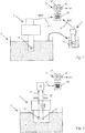
- Fig. 1 shows another example, wherein the field device 1 comprises a sensor 5 continuously measuring a measured variable p of a medium 7 located at the operation site 3, e.g. a pH-value or a concentration of an analyte comprised in the medium 7.
- the monitored variable m is equal to the measured variable p
- the reference values R(ti) are provided at consecutive times ti by reference measurements performed by another measurement device 9 on samples 11 of the medium 7 taken at the consecutive times ti.
- Fig. 2 shows another example, wherein the field device 1 comprises a temperature sensor 13 continuously measuring a temperature and means 15 detecting phase transitions of a material 17 located near the temperature sensor 13 and exhibiting a phase transition at a known transition temperature, as e.g. described in DE 10 2016 123 856 A1 .
- the transition temperature constitutes a reference value R(ti) for the temperature measured by the field device 1, which is provided by the means 15 at the consecutive times ti at which the phase transitions occur.
- Fig. 3 shows another example, wherein the field device 1 comprises a sensor 19 and a measurement electronic 21 processing a primary signal S generated by the sensor 19.
- This field device 1 comprises means 23 for superimposing a test signal H onto the primary signal S and means 25 for determining a property, like for example a frequency f or an amplitude A, of the processed test signal H' available at the output of the measurement electronic 21.
- the property of the processed test signal H' constitutes the monitored variable m available every time a test signal H is superimposed and the corresponding reference values R(ti) are given by the values of the property to be expected during proper operation of the measurement electronic 21 based on the test signal H applied.
- the deviations D(ti) are not only indicative of the performance of the measurement electronic 19, but also of other characteristics of the field device 1, like e.g. the measurement accuracy, affected by the performance of the measurement electronic 21.
- the deviations D(ti) between the measured value M(ti) of the monitored variable m determined by the field device 1 and the corresponding reference value R(ti) are preferably determined for each of the consecutive times ti, at which or for which both the measured value M(ti) and the reference value R(ti) are available.
- the thus determined deviations D(ti) and the corresponding times ti are recorded.
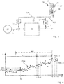
- Fig. 4 shows an example of recorded deviations D(ti), indicated by dots, recorded over a time range comprising a preliminary time interval PTI and a monitoring time interval MTI following the preliminary time interval PTI.
- the recorded deviations D(ti) are filtered by applying a filter to the recorded deviations D(ti).
- the filter can be any means or method capable of separating the signal comprised in the recorded deviations D(ti) from a noise superimposed on the signal.
- a smoothing filter or a Kalman filter can be used.
- the filtered deviations FD(ti) thus determined for each of the times ti corresponding to the times ti of the recorded deviations D(ti) can either be determined as individual values as exemplary indicated by a cross x in Fig. 4 or based on a function FD(t) of time t, also shown in Fig. 4 .
- the noise N superimposed on the filtered deviations FD(ti) is determined based on the recorded deviations D(ti) and the filtered deviations FD(ti).
- This noise N is preferably determined a as probability distribution PDF( ⁇ ) representing the noise N.
- the probability distribution PDF( ⁇ ) can be determined based on a given type of distribution, like e.g.
- a Gaussian distribution by fitting at least one parameter of the distribution to a corresponding property of the noise N determined based on the recorded deviations D(ti) and the corresponding filtered deviations FD(ti).
- the noise N is preferably determined based on a sufficiently high number of deviations D(ti), e.g. a number larger or equal to 10, preferably larger or equal to 30, of recorded deviations D(ti) and corresponding filtered deviations FD(ti).
- the noise N can e.g. be determined based on recorded deviations D(ti) and corresponding filtered deviations FD(ti) comprised in a preliminary time interval PTI, during which a correspondingly high number of deviations D(ti), have been recorded.
- a remaining time RT until the initially compliant field device 1 will no longer be compliant to the requirement can be determined.
- the remaining time RT corresponds to the time remaining until the deviations D(t) will exceed the deviation range DR.
- the remaining time RT can be determined as a remaining time interval RTI given by the amount of time remaining until the deviations D(ti) will exceed the deviation range DR and/or as a point in time t RT at which the deviations D(t) will exceed the deviation range DR.
- the remaining time RT depends on the time dependency of the deviations D(t).
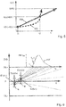
- Fig. 5 showing an example of a maximal permissible deviation MPD together with deviations A(t) comprising a linear time dependency and deviations B(t) comprising a non-linearly increasing time dependency.
- the future development of these deviations A(t), B(t) can be expected to be very different as indicated by arrows.
- time dependency of the deviations D(t) cannot be determined with a sufficient degree of accuracy and/or wherein the time dependency may change significantly during the life time of the field device 1 in an unpredictable manner, e.g. due to unexpected and/or unpredictable changes of the performance capabilities of the field device 1 and/or due to unexpected and/or unpredictable changes of environmental or other conditions the field device 1 is exposed to.
- Each determination of the remaining time RT comprises a step of for at least two different deviation pairs k, each comprising a first and a second deviation D1 k (t1 k ), D2 k (t2 k ) determined based on the filtered deviations FD(ti) comprised in the monitoring time interval (MTI), determining a simulated value SRT k of the remaining time RT by performing a Monte Carlo simulation based on the noise N and the respective deviation pair k. Following this, the remaining time RT is determined based on all previously determined simulated values SRT k and an output informing about the remaining time RT is generated.
- the invention further comprises a system for performing the method according to the invention, comprising:
- the computing means 29 can be located in the field device 1, at the operation site 3 or at a remote location. Alternatively, cloud computing can be applied.
- the data transfer means 27 preferably comprise hard wired and/or wireless transmission lines. To this extent, data bus communication systems applied in process automation, like e.g. Fieldbus, wired or wireless local area networks LAN, WLAN and/or short range wireless communication means, such as Bluetooth or Near Field Communication (NFC), can be applied.
- the data transferred to and from the computing means 29 can e.g. either be transferred directly and/or continuously, as e.g. shown in Fig. 1 , or via a buffer 33 collecting and transmitting batches of data, as e.g. shown in Fig. 2 .
- the output means 31 preferably comprise a signal output 35 providing an output signal representing the output generated by the method and/or a display 37 displaying the output.
- the remaining time RT is determined at least once and each determination of the remaining time RT is performed at the end of a monitoring time interval MTI.
- the monitoring time intervals MTI may comprise consecutive intervals, overlapping time intervals, at least one interval of a fixed length and/or at least one interval of individually determined length.
- Monitoring time intervals MTI of a fixed length are preferably applied in applications, wherein the measured values M(ti) and the corresponding reference values R(ti) are available at fairly constant rate or frequency.
- the fixed length is preferably longer than a time required for at least three consecutive deviations D(ti) to be recorded and of the same order of magnitude as a timescale on which the deviations D(ti) may exceed the deviation range DR.
- Monitoring time intervals MTI of individually determined lengths are preferably applied in applications, wherein the time differences between consecutive times ti at which or for which the deviations D(ti) are available is unknown and/or may vary significantly.
- the end of each monitoring time interval MTI is preferably determined to be equal to the time at which a predefined number n of deviations D(ti) larger or equal to three has been recorded after the beginning of the respective monitoring time MTI.
- each subsequent monitoring time interval MTI is preferably determined as a point in time after the beginning of the previous monitoring time MTI and before or at the end of the previous monitoring time interval MTI. This leads to individually determined monitoring time intervals MTI, wherein the length of each interval is determined based on the present rate of availability of the deviations D(ti).
- the noise N can be determined based on the deviations D(ti) recorded during a preliminary time interval PTI.
- the beginning of the first monitoring time MTI can be a point in time at or after the end of the preliminary time interval PTI.
- the length of at least one of the monitoring time intervals MTI can be determined to be longer or equal to the time required for a number of consecutive deviations D(ti) sufficient to determine the noise N to be recorded.
- One example of this alternative length of the monitoring time interval MTI is indicated by a dotted double arrow shown in Fig. 4 .
- the noise N, as well as the remaining time RT can be determined as described above based on the deviations D(ti) recorded during each of these correspondingly long monitoring time intervals MTI.
- the determination of the remaining time RT requires for the field device 1 to be compliant to the requirement during the preceding monitoring interval MTI. This is preferably ensured by monitoring, whether any of the determined deviations D(ti) exceeded the deviation range DR.
- safety of operating the field device 1 can be further enhanced by generating an alarm when at least one of the recorded deviations D(ti) exceeded the deviation range DR. These alarms are preferably issued by the output means 29.
- the method according to the invention is preferably resumed by determining at least one more remaining time RT based on the previously determined noise N or restarted from the beginning.
- Restarting the method from the beginning has the advantage, that the noise N will be newly determined. This has the advantage, that changes of the uncertainty inherent to the determination of the measured values M(ti) and/or the reference values R(ti) that may have been caused by the service action, will be accounted for.
- a crossing time t S is determined as the time at which a straight line passing through the first random deviation E1(t1 k ) at the first time t1 k and through the second random deviation E2(t2 k ) at the second time t2 k will exceed the deviation range DR.
- Some examples of the thus determined straight lines are shown as dotted lines in Fig. 6 together with the deviation range DR, represented by the upper and the lower deviation limit DL+, DL- shown in Fig. 6 .
- a probability density function PDF(t S ) of the crossing times t S is determined and the simulated value SRT k is determined based on the probability density function PDF(t S ) of the crossing times t S .
- the confidence level is preferably set based on the severity of the consequences involved, should the field device 1 become non-compliant during operation at the operating site 3.
- the first and the second deviation D1 k (t1 k ), D2 k (t2 k ) of each deviation pair k are determined based on the filtered deviations FD(ti) comprised in the monitoring time interval MTI. This has the advantage, that the influence of outliers or erroneous values of individual recorded deviations D(ti) on the determination of the remaining time RT is minimized.
- the first deviation D1 k (t1 k ) of each deviation pair k is preferably given by one of the filtered deviations FD(t1 k ) comprised in the monitoring time interval MTI.
- the second deviation D2 k (t2 k ) of each pair k is preferably either given by another filtered deviation FD(ti) comprised in the monitoring time interval MTI or given by a predicted deviation PD(t2 k ), forecasted for a corresponding time t2 k after the end of the monitoring time interval MTI. Examples of predicted deviations PD(tn+1), PD(tn+2) forecasted for the corresponding times tn+1, tn+2 after the end of the monitoring time interval MTI are indicated by circles in Fig.
- the predicted deviations PD(t2 k ) are preferably determined based on the filtered deviations FD(ti) comprised in the monitoring time interval MTI. They can for example be determined by applying mathematical forecasting methods, like e.g. time series forecasting. Alternatively, machine learning, deep learning or neural networks can be applied to forecast at least one predicted deviation PD(t2 k ).
- Predicted deviations PD(ti) forecasted for corresponding times ti in the very near future are very reliable.
- the reliability of the forecasts does however decrease as the time difference between the corresponding time ti and the end of the monitoring time interval MTI increases.
- the use of predicted deviations PD(ti) is preferably limited to predictions made for corresponding times ti, which exceed the end of the monitoring interval MTI by less than a small fraction of the length of the monitoring time interval MTI, e.g. by less than one fifth, preferably by less than one tenth of the length of the monitoring time interval MTI.
- the set There are different ways of determining the set of different deviation pairs k for which the simulated values SRT k are determined.
- One approach is for the set to comprise all or at least a large fraction of all the different deviation pairs k available based on either the filtered deviations FD(ti) comprised in the monitoring time interval MTI or the filtered deviations FD(ti) comprised in the monitoring time interval MTI and the predicted deviations PD(ti).
- This brute force approach renders reasonably good results. It does however require a large amount of computing power.
- the set solely comprises a limited selection of all the different deviation pairs k available. Even though the different deviation pairs k can be randomly selected, the selection is preferably optimized to enhance the capability of the method to account for the time dependency of the recorded deviations D(ti) based on the limited number of pairs k comprised in the set.
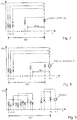
- Fig. 7 shows an example of n filtered deviations FD(t1), ..., FD(tn) comprised in the monitoring time interval MTI, wherein the set of deviation pairs k, indicated by double arrows, is selected such, that the second deviation D2 k (t2 k ) of each pair k is given by the last filtered deviation FD(tn) or one of the last filtered deviation FD(ti) comprised in the monitoring time interval MTI.
- Fig. 8 shows another example of n filtered deviations FD(t1), ..., FD(tn) comprised in the monitoring time interval MTI, wherein the set of pairs k, indicated by double arrows, is selected such, that the second deviation D2 k (t2 k ) of each pair k is given by one of the predicted deviations PD(t2 k ) or the same predicted deviation PD(t2 k ) forecasted for the corresponding time t2 k after the end of the monitoring time interval MTI.
- the selection methods shown in Fig. 7 and 8 can be further improved by only selecting deviation pairs k, wherein the time difference t2 k -t1 k between the times t2 k , t1 k corresponding to the first and the second deviation D1 k (t1 k ), D2 k (t2 k ) is larger or equal to a predetermined minimal time difference ⁇ t min .
- This way the influence of short term fluctuations of the filtered deviations FD(t) occurring shortly before or at the end of the monitoring time interval MTI, which do not represent the true time dependency of the deviations D(t) in this time range, on the determination of the remaining time RT is reduced.
- This option makes the determination of the remaining time RT more robust and stable.
- Fig. 9 shows another example wherein the set of deviation pairs k, indicated by double arrows, is selected such, the first deviation D1 k (t1 k ) of the first deviation pair k of the set is located at or near the beginning of the monitoring time interval MTI.
- the first deviation D1 k (t1 k ) of each of these deviation pairs k is selected such, that the corresponding time t1 k is larger than the corresponding time t1 k of the first deviation D1 k (t1 k ) of the previous deviation pair k and the second deviation D2 k (t2 k ) of each pair k is selected such, that the corresponding time t2 k is larger than the corresponding time t2 k of the second deviation D2 k (t2 k ) of the previous deviation pair k.
- the times elapsed between the first and second deviations D1 k (t1 k ), D2 k (t2 k ) of the consecutive deviation pairs k of the set form a sliding time window of fixed or variable length sliding along the monitoring time interval MTI.
- the deviation pairs k are preferably determined such, that the section [t1 k , t2 k ] of the monitoring time interval MTI enclosed between the two times t1 k , t2 k corresponding to the first and the second deviation D1 k (t1 k ), D2 k (t2 k ) of each pair k comprises two or more recorded deviations D(ti), wherein t1 k ⁇ ti ⁇ t2 k .
- first deviations D1 k (t1 k ) of all deviation pairs k are each given by one of the filtered deviations FD(t1 k ), comprised in the monitoring time interval MTI and second deviations D2 k (t2 k ) of the deviation pairs k are either each given by one of the filtered deviations FD(t2 k ) comprised in the monitoring time interval MTI or comprise at least one second deviation D2 k (t2 k ) given by a predicted deviation PD(t2 k ).
- each remaining time RT is determined based on the simulated values SRT k determined for each deviation pair k, e.g. as an average or a weighted average of the simulated values SRT k .
- the corresponding output generated by the method according to the invention is preferably applied by scheduling and/or performing at least one service action, e.g. a calibration and/or a maintenance procedure, on the field device 1 before the point in time t RT given by the remaining time RT, at which the deviations D(ti) will exceed the deviation range DR.
- the method according to the invention is preferably resumed based on the previously determined noise N or restarted form the beginning as described above.
- the method according to the invention can be further improved by following the determination of at least one remaining time RT determining at least one more remaining time RT as described above before the point in time t RT at which the deviations D(ti) will exceed the deviation range DR according to the previously determined remaining time RT.
- the output informing about the remaining time RT is preferably updated accordingly every time a new remaining time RT has been determined.
- scheduling and/or performance of the service actions is preferably performed based on the most recently determined remaining time RT. Again, following any of these service action, the method according to the invention is preferably resumed based on the previously determined noise N or restarted form the beginning as described above.
- the consecutive determination of two or more remaining times RT is not mandatory, it enhances the capability of the method to detect and account for more sudden changes of the characteristic of the field device 1, e.g. changes due to unexpected wear and tear of the field device 1 and/or due to changes of environment and/or operating conditions the field device 1 is exposed to.
- the method according to the invention can be further improved by at least once re-determining the noise N as described above based on more recently recorded deviations D(ti) and the corresponding filtered deviations FD(ti).
- any redetermination of the noise N is preferably performed based on a sufficiently large number of more recently recorded deviations D(ti) and the corresponding filtered deviations FD(ti).
- tests can be performed based on recently recorded deviations D(ti) testing whether the noise N has changed significantly since it has last been determined.
- test methods used in statistical data analysis like e.g. hypothesis-testing, e.g. based on Chi-Square tests, can be applied. Based on these tests changes of the noise N can be detected with a fairly high level of confidence based on a number of recently recorded deviations D(ti) and the corresponding filtered deviations FD(ti), which is smaller than the number of recorded and filtered deviations D(ti), FD(ti) required to re-determine the noise N with a correspondingly high level of accuracy.
- the noise N is preferably only re-determined in case a significant change of the noise N has been determined based on the tests.
- the noise N can be continuously updated, based on the deviations D(ti) recorded after the first determination of the noise N and the corresponding filtered deviations FD(ti).
- monitoring time intervals MTI comprising at least ten, preferably at least thirty recorded deviations D(ti)
- the noise N and the remaining time RT can both be determined at the end of each of these monitoring time intervals MTI based on the recorded deviations D(ti) comprised therein.
- List of reference numerals 1 field device 21 measurement electronics 3 operating site 23 means for superimposing a test signal 5 sensor 25 means 7 medium 27 data transfer means 9 measurement device 29 computing means 11 sample 31 output means 13 temperature sensor 33 buffer 15 means 35 signal output 17 material 37 display 19 sensor
Landscapes
- Physics & Mathematics (AREA)
- General Physics & Mathematics (AREA)
- Health & Medical Sciences (AREA)
- Chemical & Material Sciences (AREA)
- Life Sciences & Earth Sciences (AREA)
- Engineering & Computer Science (AREA)
- Automation & Control Theory (AREA)
- Immunology (AREA)
- Pathology (AREA)
- Molecular Biology (AREA)
- Biochemistry (AREA)
- Chemical Kinetics & Catalysis (AREA)
- Electrochemistry (AREA)
- Analytical Chemistry (AREA)
- General Health & Medical Sciences (AREA)
- Fluid Mechanics (AREA)
- Electromagnetism (AREA)
- Manufacturing & Machinery (AREA)
- Quality & Reliability (AREA)
- Testing And Monitoring For Control Systems (AREA)
- Measuring And Recording Apparatus For Diagnosis (AREA)
- Testing Of Devices, Machine Parts, Or Other Structures Thereof (AREA)
Applications Claiming Priority (1)
| Application Number | Priority Date | Filing Date | Title |
|---|---|---|---|
| DE102019112745 | 2019-05-15 |
Publications (2)
| Publication Number | Publication Date |
|---|---|
| EP3739403A1 true EP3739403A1 (de) | 2020-11-18 |
| EP3739403B1 EP3739403B1 (de) | 2022-12-07 |
Family
ID=70277199
Family Applications (1)
| Application Number | Title | Priority Date | Filing Date |
|---|---|---|---|
| EP20168733.2A Active EP3739403B1 (de) | 2019-05-15 | 2020-04-08 | Verfahren zum betrieb und zur prädiktiven überwachung eines feldgerätes |
Country Status (3)
| Country | Link |
|---|---|
| US (1) | US11435212B2 (de) |
| EP (1) | EP3739403B1 (de) |
| CN (1) | CN111947688B (de) |
Cited By (2)
| Publication number | Priority date | Publication date | Assignee | Title |
|---|---|---|---|---|
| EP4002041A1 (de) * | 2020-11-19 | 2022-05-25 | Endress+Hauser Group Services AG | Verfahren zur prädiktiven überwachung einer variablen eines mediums und der messgenauigkeit einer vorrichtung, die diese variable misst |
| DE102021130639A1 (de) | 2021-11-23 | 2023-05-25 | Endress+Hauser Conducta Gmbh+Co. Kg | Verfahren zum Bestimmen anwendungsspezifischer Gesamtplausibilitäten von Messwerten mindestens einer von einem Messsystem in einer spezifischen Anwendung gemessenen Messgröße |
Families Citing this family (3)
| Publication number | Priority date | Publication date | Assignee | Title |
|---|---|---|---|---|
| EP4273719A1 (de) * | 2022-05-06 | 2023-11-08 | Endress+Hauser Group Services AG | Filterverfahren zur filterung von messwerten einer messgrösse und verfahren zur anwendung dieses filterverfahrens |
| WO2024263965A1 (en) * | 2023-06-21 | 2024-12-26 | Tomea LLC | System and methods for water testing compliance |
| CN119848612B (zh) * | 2025-03-19 | 2025-05-16 | 山西城安数智科技有限公司 | 一种基于人工智能的化工设备安全监测方法及系统 |
Citations (3)
| Publication number | Priority date | Publication date | Assignee | Title |
|---|---|---|---|---|
| EP2602680B1 (de) | 2011-12-09 | 2014-06-18 | Endress + Hauser Messtechnik GmbH+Co. KG | Verfahren zur Bestimmung eines Kalibrierzeitintervalls zur Kalibrierung einer Messvorrichtung |
| DE102014118845A1 (de) * | 2014-12-17 | 2016-06-23 | Endress + Hauser Messtechnik Gmbh+Co. Kg | Verfahren und Vorrichtung zur Erkennung von Anomalien von Feldgeräten |
| DE102016123856A1 (de) | 2016-12-08 | 2018-06-14 | Endress + Hauser Wetzer Gmbh + Co. Kg | Verfahren zur in situ Kalibrierung eines Thermometers |
Family Cites Families (7)
| Publication number | Priority date | Publication date | Assignee | Title |
|---|---|---|---|---|
| DE50306976D1 (de) * | 2003-11-19 | 2007-05-16 | Siemens Ag | Verfahren zur Überwachung einer technischen Einrichtung |
| DE102005062388A1 (de) * | 2005-12-23 | 2007-06-28 | Endress + Hauser Conducta Gesellschaft für Mess- und Regeltechnik mbH + Co. KG | Kalibrierung im Laborreferenzverfahren |
| US8103463B2 (en) * | 2006-09-21 | 2012-01-24 | Impact Technologies, Llc | Systems and methods for predicting failure of electronic systems and assessing level of degradation and remaining useful life |
| US20090070069A1 (en) | 2007-09-07 | 2009-03-12 | Csi Technology, Inc. | Apparatus and method for optimizing measurement reporting in a field device |
| EP2551650B1 (de) * | 2011-07-27 | 2019-09-25 | Endress+Hauser Consult AG | Kalibrierverfahren |
| EP3002651B1 (de) * | 2014-09-30 | 2021-01-13 | Endress+Hauser Group Services AG | Überwachungseinrichtung und Überwachungsverfahren zur Überwachung von mindestens einem Schritt eines an einem Industriestandort durchgeführten Prozesses |
| DE102017116167A1 (de) | 2017-07-18 | 2019-01-24 | Endress+Hauser Process Solutions Ag | Verfahren zum Überwachen einer Automatisierungsanlage |
-
2020
- 2020-04-08 EP EP20168733.2A patent/EP3739403B1/de active Active
- 2020-05-13 CN CN202010401333.0A patent/CN111947688B/zh active Active
- 2020-05-15 US US16/875,678 patent/US11435212B2/en active Active
Patent Citations (3)
| Publication number | Priority date | Publication date | Assignee | Title |
|---|---|---|---|---|
| EP2602680B1 (de) | 2011-12-09 | 2014-06-18 | Endress + Hauser Messtechnik GmbH+Co. KG | Verfahren zur Bestimmung eines Kalibrierzeitintervalls zur Kalibrierung einer Messvorrichtung |
| DE102014118845A1 (de) * | 2014-12-17 | 2016-06-23 | Endress + Hauser Messtechnik Gmbh+Co. Kg | Verfahren und Vorrichtung zur Erkennung von Anomalien von Feldgeräten |
| DE102016123856A1 (de) | 2016-12-08 | 2018-06-14 | Endress + Hauser Wetzer Gmbh + Co. Kg | Verfahren zur in situ Kalibrierung eines Thermometers |
Cited By (3)
| Publication number | Priority date | Publication date | Assignee | Title |
|---|---|---|---|---|
| EP4002041A1 (de) * | 2020-11-19 | 2022-05-25 | Endress+Hauser Group Services AG | Verfahren zur prädiktiven überwachung einer variablen eines mediums und der messgenauigkeit einer vorrichtung, die diese variable misst |
| US11994488B2 (en) | 2020-11-19 | 2024-05-28 | Endress+Hauser Group Services Ag | Method of predictive monitoring of a variable of a medium and of a measurement accuracy of a measurement device measuring this variable |
| DE102021130639A1 (de) | 2021-11-23 | 2023-05-25 | Endress+Hauser Conducta Gmbh+Co. Kg | Verfahren zum Bestimmen anwendungsspezifischer Gesamtplausibilitäten von Messwerten mindestens einer von einem Messsystem in einer spezifischen Anwendung gemessenen Messgröße |
Also Published As
| Publication number | Publication date |
|---|---|
| EP3739403B1 (de) | 2022-12-07 |
| CN111947688B (zh) | 2022-08-30 |
| US11435212B2 (en) | 2022-09-06 |
| CN111947688A (zh) | 2020-11-17 |
| US20200363245A1 (en) | 2020-11-19 |
Similar Documents
| Publication | Publication Date | Title |
|---|---|---|
| EP3739403B1 (de) | Verfahren zum betrieb und zur prädiktiven überwachung eines feldgerätes | |
| EP2551650B1 (de) | Kalibrierverfahren | |
| US10747188B2 (en) | Information processing apparatus, information processing method, and, recording medium | |
| EP1247268B1 (de) | Zweidraht-temperaturübertrager mit selbstprüfung und niedriger leistung | |
| EP2602680B1 (de) | Verfahren zur Bestimmung eines Kalibrierzeitintervalls zur Kalibrierung einer Messvorrichtung | |
| US10901371B2 (en) | Method of determining a calibration or maintenance time interval | |
| EP2856269B1 (de) | Überwachung des stroms in einer prozess-stromschleife | |
| JP4858255B2 (ja) | シミュレーションにより異常診断支援を行うフィールド機器 | |
| US20140350873A1 (en) | Method for generating a signal indicating an oscillation in an electrical energy supply network | |
| EP2631724B1 (de) | Verfahren zur messung des gesundheitsindex von anlagen mit reflexion des status von unterbaugruppen und computerlesbares speichermedium mit darauf gespeichertem programm zur ausführung dieses verfahrens | |
| US20160138960A1 (en) | Method for operating a flow meter | |
| JP4369313B2 (ja) | 臨床検査システム | |
| US11994488B2 (en) | Method of predictive monitoring of a variable of a medium and of a measurement accuracy of a measurement device measuring this variable | |
| JP4372473B2 (ja) | データ管理システムおよびそれに適用される分析装置 | |
| EP2597436A1 (de) | Verfahren zur Bestimmung eines Kalibrierzeitintervalls für ein Messinstrument | |
| CN103733041A (zh) | 管理装置、管理方法、程序及记录介质 | |
| KR102385007B1 (ko) | 산업용 측정장비 상태 정보(시계열 자료) 신뢰수준 기반 교정 시점 예측 장치 및 방법 | |
| CN114545107A (zh) | 用测量仪器监视过程设备中测量的被测变量的方法 | |
| US20240200990A1 (en) | Method of measuring measurands of a medium and a measurement system configured to perform this method | |
| EP2587326B1 (de) | Verfahren zur Bewertung eines mit dem Betrieb eines Messgerätes an einer Messstelle in einem industriellen Prozess verbunden Risikos | |
| CN120344931A (zh) | 流体网络的整体多向异常和场景转变检测 | |
| JP2024040655A (ja) | 故障予測システムおよび故障予測方法 | |
| Lubcke | Methods to interconnect functional safety and self-monitoring of field devices in process control loops | |
| Pugh et al. | Benefits of Long-Range Wireless Ultrasonic Corrosion Sensors in Refinery Applications | |
| RU2491510C1 (ru) | Способ контроля метрологической исправности интеллектуального средства измерений |
Legal Events
| Date | Code | Title | Description |
|---|---|---|---|
| PUAI | Public reference made under article 153(3) epc to a published international application that has entered the european phase |
Free format text: ORIGINAL CODE: 0009012 |
|
| STAA | Information on the status of an ep patent application or granted ep patent |
Free format text: STATUS: THE APPLICATION HAS BEEN PUBLISHED |
|
| AK | Designated contracting states |
Kind code of ref document: A1 Designated state(s): AL AT BE BG CH CY CZ DE DK EE ES FI FR GB GR HR HU IE IS IT LI LT LU LV MC MK MT NL NO PL PT RO RS SE SI SK SM TR |
|
| AX | Request for extension of the european patent |
Extension state: BA ME |
|
| STAA | Information on the status of an ep patent application or granted ep patent |
Free format text: STATUS: REQUEST FOR EXAMINATION WAS MADE |
|
| 17P | Request for examination filed |
Effective date: 20201120 |
|
| RBV | Designated contracting states (corrected) |
Designated state(s): AL AT BE BG CH CY CZ DE DK EE ES FI FR GB GR HR HU IE IS IT LI LT LU LV MC MK MT NL NO PL PT RO RS SE SI SK SM TR |
|
| GRAP | Despatch of communication of intention to grant a patent |
Free format text: ORIGINAL CODE: EPIDOSNIGR1 |
|
| STAA | Information on the status of an ep patent application or granted ep patent |
Free format text: STATUS: GRANT OF PATENT IS INTENDED |
|
| RIC1 | Information provided on ipc code assigned before grant |
Ipc: G05B 23/02 20060101ALI20220805BHEP Ipc: G05B 19/042 20060101AFI20220805BHEP |
|
| INTG | Intention to grant announced |
Effective date: 20220914 |
|
| GRAS | Grant fee paid |
Free format text: ORIGINAL CODE: EPIDOSNIGR3 |
|
| GRAA | (expected) grant |
Free format text: ORIGINAL CODE: 0009210 |
|
| STAA | Information on the status of an ep patent application or granted ep patent |
Free format text: STATUS: THE PATENT HAS BEEN GRANTED |
|
| AK | Designated contracting states |
Kind code of ref document: B1 Designated state(s): AL AT BE BG CH CY CZ DE DK EE ES FI FR GB GR HR HU IE IS IT LI LT LU LV MC MK MT NL NO PL PT RO RS SE SI SK SM TR |
|
| REG | Reference to a national code |
Ref country code: GB Ref legal event code: FG4D |
|
| REG | Reference to a national code |
Ref country code: CH Ref legal event code: EP Ref country code: AT Ref legal event code: REF Ref document number: 1536660 Country of ref document: AT Kind code of ref document: T Effective date: 20221215 |
|
| REG | Reference to a national code |
Ref country code: DE Ref legal event code: R096 Ref document number: 602020006711 Country of ref document: DE |
|
| REG | Reference to a national code |
Ref country code: IE Ref legal event code: FG4D |
|
| REG | Reference to a national code |
Ref country code: NL Ref legal event code: FP |
|
| REG | Reference to a national code |
Ref country code: LT Ref legal event code: MG9D |
|
| PG25 | Lapsed in a contracting state [announced via postgrant information from national office to epo] |
Ref country code: SE Free format text: LAPSE BECAUSE OF FAILURE TO SUBMIT A TRANSLATION OF THE DESCRIPTION OR TO PAY THE FEE WITHIN THE PRESCRIBED TIME-LIMIT Effective date: 20221207 Ref country code: NO Free format text: LAPSE BECAUSE OF FAILURE TO SUBMIT A TRANSLATION OF THE DESCRIPTION OR TO PAY THE FEE WITHIN THE PRESCRIBED TIME-LIMIT Effective date: 20230307 Ref country code: LT Free format text: LAPSE BECAUSE OF FAILURE TO SUBMIT A TRANSLATION OF THE DESCRIPTION OR TO PAY THE FEE WITHIN THE PRESCRIBED TIME-LIMIT Effective date: 20221207 Ref country code: FI Free format text: LAPSE BECAUSE OF FAILURE TO SUBMIT A TRANSLATION OF THE DESCRIPTION OR TO PAY THE FEE WITHIN THE PRESCRIBED TIME-LIMIT Effective date: 20221207 Ref country code: ES Free format text: LAPSE BECAUSE OF FAILURE TO SUBMIT A TRANSLATION OF THE DESCRIPTION OR TO PAY THE FEE WITHIN THE PRESCRIBED TIME-LIMIT Effective date: 20221207 |
|
| REG | Reference to a national code |
Ref country code: AT Ref legal event code: MK05 Ref document number: 1536660 Country of ref document: AT Kind code of ref document: T Effective date: 20221207 |
|
| PG25 | Lapsed in a contracting state [announced via postgrant information from national office to epo] |
Ref country code: RS Free format text: LAPSE BECAUSE OF FAILURE TO SUBMIT A TRANSLATION OF THE DESCRIPTION OR TO PAY THE FEE WITHIN THE PRESCRIBED TIME-LIMIT Effective date: 20221207 Ref country code: PL Free format text: LAPSE BECAUSE OF FAILURE TO SUBMIT A TRANSLATION OF THE DESCRIPTION OR TO PAY THE FEE WITHIN THE PRESCRIBED TIME-LIMIT Effective date: 20221207 Ref country code: LV Free format text: LAPSE BECAUSE OF FAILURE TO SUBMIT A TRANSLATION OF THE DESCRIPTION OR TO PAY THE FEE WITHIN THE PRESCRIBED TIME-LIMIT Effective date: 20221207 Ref country code: HR Free format text: LAPSE BECAUSE OF FAILURE TO SUBMIT A TRANSLATION OF THE DESCRIPTION OR TO PAY THE FEE WITHIN THE PRESCRIBED TIME-LIMIT Effective date: 20221207 Ref country code: GR Free format text: LAPSE BECAUSE OF FAILURE TO SUBMIT A TRANSLATION OF THE DESCRIPTION OR TO PAY THE FEE WITHIN THE PRESCRIBED TIME-LIMIT Effective date: 20230308 |
|
| P01 | Opt-out of the competence of the unified patent court (upc) registered |
Effective date: 20230601 |
|
| PG25 | Lapsed in a contracting state [announced via postgrant information from national office to epo] |
Ref country code: SM Free format text: LAPSE BECAUSE OF FAILURE TO SUBMIT A TRANSLATION OF THE DESCRIPTION OR TO PAY THE FEE WITHIN THE PRESCRIBED TIME-LIMIT Effective date: 20221207 Ref country code: RO Free format text: LAPSE BECAUSE OF FAILURE TO SUBMIT A TRANSLATION OF THE DESCRIPTION OR TO PAY THE FEE WITHIN THE PRESCRIBED TIME-LIMIT Effective date: 20221207 Ref country code: PT Free format text: LAPSE BECAUSE OF FAILURE TO SUBMIT A TRANSLATION OF THE DESCRIPTION OR TO PAY THE FEE WITHIN THE PRESCRIBED TIME-LIMIT Effective date: 20230410 Ref country code: EE Free format text: LAPSE BECAUSE OF FAILURE TO SUBMIT A TRANSLATION OF THE DESCRIPTION OR TO PAY THE FEE WITHIN THE PRESCRIBED TIME-LIMIT Effective date: 20221207 Ref country code: CZ Free format text: LAPSE BECAUSE OF FAILURE TO SUBMIT A TRANSLATION OF THE DESCRIPTION OR TO PAY THE FEE WITHIN THE PRESCRIBED TIME-LIMIT Effective date: 20221207 Ref country code: AT Free format text: LAPSE BECAUSE OF FAILURE TO SUBMIT A TRANSLATION OF THE DESCRIPTION OR TO PAY THE FEE WITHIN THE PRESCRIBED TIME-LIMIT Effective date: 20221207 |
|
| PG25 | Lapsed in a contracting state [announced via postgrant information from national office to epo] |
Ref country code: SK Free format text: LAPSE BECAUSE OF FAILURE TO SUBMIT A TRANSLATION OF THE DESCRIPTION OR TO PAY THE FEE WITHIN THE PRESCRIBED TIME-LIMIT Effective date: 20221207 Ref country code: IS Free format text: LAPSE BECAUSE OF FAILURE TO SUBMIT A TRANSLATION OF THE DESCRIPTION OR TO PAY THE FEE WITHIN THE PRESCRIBED TIME-LIMIT Effective date: 20230407 Ref country code: AL Free format text: LAPSE BECAUSE OF FAILURE TO SUBMIT A TRANSLATION OF THE DESCRIPTION OR TO PAY THE FEE WITHIN THE PRESCRIBED TIME-LIMIT Effective date: 20221207 |
|
| REG | Reference to a national code |
Ref country code: DE Ref legal event code: R097 Ref document number: 602020006711 Country of ref document: DE |
|
| PLBE | No opposition filed within time limit |
Free format text: ORIGINAL CODE: 0009261 |
|
| STAA | Information on the status of an ep patent application or granted ep patent |
Free format text: STATUS: NO OPPOSITION FILED WITHIN TIME LIMIT |
|
| PG25 | Lapsed in a contracting state [announced via postgrant information from national office to epo] |
Ref country code: DK Free format text: LAPSE BECAUSE OF FAILURE TO SUBMIT A TRANSLATION OF THE DESCRIPTION OR TO PAY THE FEE WITHIN THE PRESCRIBED TIME-LIMIT Effective date: 20221207 |
|
| 26N | No opposition filed |
Effective date: 20230908 |
|
| PG25 | Lapsed in a contracting state [announced via postgrant information from national office to epo] |
Ref country code: SI Free format text: LAPSE BECAUSE OF FAILURE TO SUBMIT A TRANSLATION OF THE DESCRIPTION OR TO PAY THE FEE WITHIN THE PRESCRIBED TIME-LIMIT Effective date: 20221207 |
|
| PG25 | Lapsed in a contracting state [announced via postgrant information from national office to epo] |
Ref country code: LU Free format text: LAPSE BECAUSE OF NON-PAYMENT OF DUE FEES Effective date: 20230408 |
|
| REG | Reference to a national code |
Ref country code: BE Ref legal event code: MM Effective date: 20230430 |
|
| PG25 | Lapsed in a contracting state [announced via postgrant information from national office to epo] |
Ref country code: MC Free format text: LAPSE BECAUSE OF FAILURE TO SUBMIT A TRANSLATION OF THE DESCRIPTION OR TO PAY THE FEE WITHIN THE PRESCRIBED TIME-LIMIT Effective date: 20221207 |
|
| PG25 | Lapsed in a contracting state [announced via postgrant information from national office to epo] |
Ref country code: MC Free format text: LAPSE BECAUSE OF FAILURE TO SUBMIT A TRANSLATION OF THE DESCRIPTION OR TO PAY THE FEE WITHIN THE PRESCRIBED TIME-LIMIT Effective date: 20221207 |
|
| REG | Reference to a national code |
Ref country code: IE Ref legal event code: MM4A |
|
| PG25 | Lapsed in a contracting state [announced via postgrant information from national office to epo] |
Ref country code: BE Free format text: LAPSE BECAUSE OF NON-PAYMENT OF DUE FEES Effective date: 20230430 |
|
| PG25 | Lapsed in a contracting state [announced via postgrant information from national office to epo] |
Ref country code: IE Free format text: LAPSE BECAUSE OF NON-PAYMENT OF DUE FEES Effective date: 20230408 |
|
| PG25 | Lapsed in a contracting state [announced via postgrant information from national office to epo] |
Ref country code: IE Free format text: LAPSE BECAUSE OF NON-PAYMENT OF DUE FEES Effective date: 20230408 |
|
| PG25 | Lapsed in a contracting state [announced via postgrant information from national office to epo] |
Ref country code: BG Free format text: LAPSE BECAUSE OF FAILURE TO SUBMIT A TRANSLATION OF THE DESCRIPTION OR TO PAY THE FEE WITHIN THE PRESCRIBED TIME-LIMIT Effective date: 20221207 |
|
| PG25 | Lapsed in a contracting state [announced via postgrant information from national office to epo] |
Ref country code: BG Free format text: LAPSE BECAUSE OF FAILURE TO SUBMIT A TRANSLATION OF THE DESCRIPTION OR TO PAY THE FEE WITHIN THE PRESCRIBED TIME-LIMIT Effective date: 20221207 |
|
| PGFP | Annual fee paid to national office [announced via postgrant information from national office to epo] |
Ref country code: NL Payment date: 20250418 Year of fee payment: 6 |
|
| PGFP | Annual fee paid to national office [announced via postgrant information from national office to epo] |
Ref country code: DE Payment date: 20250422 Year of fee payment: 6 |
|
| PGFP | Annual fee paid to national office [announced via postgrant information from national office to epo] |
Ref country code: GB Payment date: 20250423 Year of fee payment: 6 |
|
| PGFP | Annual fee paid to national office [announced via postgrant information from national office to epo] |
Ref country code: IT Payment date: 20250424 Year of fee payment: 6 |
|
| PGFP | Annual fee paid to national office [announced via postgrant information from national office to epo] |
Ref country code: FR Payment date: 20250425 Year of fee payment: 6 |
|
| PGFP | Annual fee paid to national office [announced via postgrant information from national office to epo] |
Ref country code: CH Payment date: 20250501 Year of fee payment: 6 |
|
| PG25 | Lapsed in a contracting state [announced via postgrant information from national office to epo] |
Ref country code: CY Free format text: LAPSE BECAUSE OF FAILURE TO SUBMIT A TRANSLATION OF THE DESCRIPTION OR TO PAY THE FEE WITHIN THE PRESCRIBED TIME-LIMIT; INVALID AB INITIO Effective date: 20200408 |
|
| PG25 | Lapsed in a contracting state [announced via postgrant information from national office to epo] |
Ref country code: HU Free format text: LAPSE BECAUSE OF FAILURE TO SUBMIT A TRANSLATION OF THE DESCRIPTION OR TO PAY THE FEE WITHIN THE PRESCRIBED TIME-LIMIT; INVALID AB INITIO Effective date: 20200408 |
|
| PG25 | Lapsed in a contracting state [announced via postgrant information from national office to epo] |
Ref country code: TR Free format text: LAPSE BECAUSE OF FAILURE TO SUBMIT A TRANSLATION OF THE DESCRIPTION OR TO PAY THE FEE WITHIN THE PRESCRIBED TIME-LIMIT Effective date: 20221207 |