EP3739735B1 - Motor - Google Patents
Motor Download PDFInfo
- Publication number
- EP3739735B1 EP3739735B1 EP18899599.7A EP18899599A EP3739735B1 EP 3739735 B1 EP3739735 B1 EP 3739735B1 EP 18899599 A EP18899599 A EP 18899599A EP 3739735 B1 EP3739735 B1 EP 3739735B1
- Authority
- EP
- European Patent Office
- Prior art keywords
- segment
- tooth
- coil
- around
- wound around
- Prior art date
- Legal status (The legal status is an assumption and is not a legal conclusion. Google has not performed a legal analysis and makes no representation as to the accuracy of the status listed.)
- Active
Links
Images


Classifications
-
- H—ELECTRICITY
- H02—GENERATION; CONVERSION OR DISTRIBUTION OF ELECTRIC POWER
- H02K—DYNAMO-ELECTRIC MACHINES
- H02K23/00—DC commutator motors or generators having mechanical commutator; Universal AC/DC commutator motors
- H02K23/26—DC commutator motors or generators having mechanical commutator; Universal AC/DC commutator motors characterised by the armature windings
- H02K23/38—DC commutator motors or generators having mechanical commutator; Universal AC/DC commutator motors characterised by the armature windings having winding or connection for improving commutation, e.g. equipotential connection
-
- H—ELECTRICITY
- H02—GENERATION; CONVERSION OR DISTRIBUTION OF ELECTRIC POWER
- H02K—DYNAMO-ELECTRIC MACHINES
- H02K13/00—Structural associations of current collectors with motors or generators, e.g. brush mounting plates or connections to windings; Disposition of current collectors in motors or generators; Arrangements for improving commutation
- H02K13/04—Connections between commutator segments and windings
-
- H—ELECTRICITY
- H02—GENERATION; CONVERSION OR DISTRIBUTION OF ELECTRIC POWER
- H02K—DYNAMO-ELECTRIC MACHINES
- H02K15/00—Processes or apparatus specially adapted for manufacturing, assembling, maintaining or repairing of dynamo-electric machines
- H02K15/08—Forming windings by laying conductors into or around core parts
- H02K15/09—Forming windings by laying conductors into or around core parts by laying conductors into slotted rotors
-
- H—ELECTRICITY
- H02—GENERATION; CONVERSION OR DISTRIBUTION OF ELECTRIC POWER
- H02K—DYNAMO-ELECTRIC MACHINES
- H02K23/00—DC commutator motors or generators having mechanical commutator; Universal AC/DC commutator motors
- H02K23/26—DC commutator motors or generators having mechanical commutator; Universal AC/DC commutator motors characterised by the armature windings
-
- H—ELECTRICITY
- H02—GENERATION; CONVERSION OR DISTRIBUTION OF ELECTRIC POWER
- H02K—DYNAMO-ELECTRIC MACHINES
- H02K3/00—Details of windings
- H02K3/04—Windings characterised by the conductor shape, form or construction, e.g. with bar conductors
- H02K3/28—Layout of windings or of connections between windings
Definitions
- the present invention relates to a motor.
- a brushed motor there is a three-phase brushed DC motor (hereinafter referred to as a brushed motor) mounted on a vehicle or the like.
- This brushed motor includes a cylindrical yoke having a permanent magnet attached to an inner peripheral surface thereof, and an armature rotatably provided radially inside the yoke.
- the armature has a rotary shaft, an armature core externally fitted and fixed to the rotary shaft, and a commutator externally fitted and fixed to the rotary shaft so as to be adjacent to the armature core.
- the armature core has a plurality of teeth extending along a radial direction and disposed radially. Dovetail groove-like slots are formed between each tooth adjacent in a circumferential direction. A coil is wound around each tooth via these slots.
- a plurality of segments are disposed on the commutator along the circumferential direction.
- the coil is connected to these segments.
- a brush comes into slide contact with each segment.
- the brush is electrically connected to an external power supply. By applying the power of the external power supply to each segment via the brush, a current is supplied to each coil.
- armature core a predetermined magnetic field is formed in the armature core, and magnetic attractive force or repulsive force is generated between the magnetic field and the permanent magnet. Hence, the armature rotates.
- a winding start terminal of the coil is connected to the seventh segment.
- the coil is connected from the seventh segment to the first segment, and is wound around the first tooth in a forward direction from the first segment.
- the coil is connected from the first tooth to the second segment, and is connected from the second segment to the eighth segment.
- the coil is wound around the third tooth in a reverse direction from the eighth segment, and is connected from the third tooth to the third segment.
- the coil is connected from the third segment to the ninth segment, and is wound around the fifth tooth in the forward direction from the ninth segment.
- the coil is connected from the fifth tooth to the tenth segment, and is connected from the tenth segment to the fourth segment.
- the coil is wound around the first tooth in the reverse direction from the fourth segment, and is connected from the first tooth to the eleventh segment.
- the coil is connected from the eleventh segment to the fifth segment, and is wound around the third tooth in the forward direction from the fifth segment.
- the coil is connected from the third tooth to the sixth segment, and is connected from the sixth segment to the twelfth segment.
- the coil is wound around the fifth tooth in the reverse direction from the twelfth segment.
- a winding end terminal pulled out from the fifth tooth is again connected to the seventh segment.
- the segments having the same potential are short-circuited by an equalizer (connection line) (for example, see Patent Document 1).
- each tooth includes a first coil electrically connected between adjacent segments and wound in the forward direction, and a second coil electrically connected between other adjacent segments and wound in the reverse direction.
- Relative positions of the segment to which the winding start terminal of the first coil is connected and the segment to which the winding start terminal of the second coil is connected are set to correspond to relative positions of a pair of brushes.
- the segments having the same potential are short-circuited by an equalizer (connection line) (for example, see Patent Document 2).
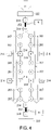
- FIG. 4 is an explanatory diagram showing an electric circuit of a coil 207 in Patent Document 2.
- the coil 207 is in a form in which electric circuits are connected in parallel between the seventh segment 214 connected with the first segment 214 via an equalizer 252 and the tenth segment 214 connected with the fourth segment 214 via the equalizer 252.
- a current supplied to the brush 222 has a current value of 4[i]
- a current supplied to the equalizer 252 between the first and seventh segments 214 has a current value of 4[i].
- the current supplied to the equalizer 252 between the fourth and tenth segments 214 also has a current value of 4[i].
- the value of the current flowing through the equalizer 252 may increase, and there is a possibility that the equalizer 252 may be damaged.
- Patent Document 2 since the coil wound around the teeth is connected to each segment, the value of the current flowing through the equalizer can be reduced as compared with Patent Document 1.
- the winding device to realize a coil winding structure as in Patent Document 2, it is necessary for the winding device to perform the coil winding operation on two coils simultaneously by a so-called double flyer that has two flyers for drawing the coils. For this reason, the winding device becomes complex.
- the double flyer since the double flyer is used, the amount of winding of the coil is increased, and there is a problem that it is difficult to improve a space factor of the coil.
- the present invention provides a motor that can be reduced in size and that is capable of reducing the value of the current flowing through the equalizer, simplifying the winding device, improving the space factor of the coil, and facilitating the winding operation.
- a motor includes: a yoke having four magnetic poles; an armature core, having a rotary shaft rotatably provided radially inside the yoke, six teeth attached to the rotary shaft and extending radially outward, and six slots formed between each of the teeth adjacent in a circumferential direction; a coil wound around each of the teeth; a commutator provided adjacent to the armature core on the rotary shaft, on which twelve segments are disposed in the circumferential direction; and a plurality of brushes supplying power to the coil via each of the segments.
- a winding start terminal of the coil is connected to the first segment, and the coil is pulled around in one direction in a rotational direction of the rotary shaft from the first segment and wound around the fifth tooth in a forward direction, pulled around in the one direction from the fifth tooth and wound around the second tooth in the forward direction, pulled around in the one direction from the second tooth and connected to the twelfth segment, pulled around in the one direction from the twelfth segment and connected to the sixth segment, pulled around in the one direction from the sixth segment and wound around the sixth tooth in a reverse direction opposite the forward direction, pulled around in the one direction from the sixth tooth and wound around the third tooth in the reverse direction, pulled around in the one direction from the third tooth and connected to the eleventh segment, pulled around in the one direction from the eleventh segment and connected to the fifth segment, pulled around in the one direction from the fifth segment and wound around the first tooth in the forward direction
- the motor can be reduced in size, and the coil wound around the teeth can be connected to each segment. Hence, it can be prevented that a value of a current flowing through the coil connecting the segments having the same potential may increase.
- the coil winding operation can be performed continuously in a single stroke.
- a winding device can be simplified and the coil winding operation can be facilitated.
- each coil is coated.
- the coating is performed in which the amount of coating has substantially the same thickness even when wire diameters are different.
- a motor can be provided that can be reduced in size and that is capable of reducing a value of a current flowing through a connection line, simplifying a winding device, improving a space factor of a coil, and facilitating a winding operation.
- FIG. 1 is a cross-sectional view of a brushed motor 1 along an axial direction.
- the brushed motor 1 is, for example, used as a driving source for electrical equipment mounted on a vehicle.
- the brushed motor 1 includes an armature 3 rotatably provided in a substantially bottomed cylindrical yoke 2, and an opening part 2c of the yoke 2 is closed with an end bracket 17.
- the armature 3 includes an armature core 6 fixed to a rotary shaft 5, a coil 7 wound around the armature core 6, and a commutator 13 disposed at one end of the armature core 6.
- the armature core 6 is formed by, for example, laminating a plurality of ring-shaped metal plates 8 in the axial direction.
- the armature core 6 may be formed by compression molding soft magnetic powder.
- T-shaped teeth 50 are formed radially at equal intervals along the circumferential direction when viewed from the axial direction. Since the plurality of metal plates 8 are externally fitted to the rotary shaft 5, dovetail groove-like slots 51 are formed between adjacent teeth 50 on an outer periphery of the armature core 6. The slots 51 extend along the axial direction, and there are six slots 51 formed at equal intervals along the circumferential direction. Through these slots 51, the coil 7 is wound around the teeth 50 by a concentrated winding method (the details will be described later).
- the commutator 13 is externally fitted and fixed to one end of the rotary shaft 5. Twelve segments 14 formed of a conductive material are attached to an outer peripheral surface of the commutator 13.
- the brushed motor 1 of the present embodiment is a so-called four-pole six-slot twelve-segment (double segment) motor, having four permanent magnets 4 (the number of magnetic poles is four), six slots 51 (six teeth 50), and twelve segments 14.
- the segments 14 are formed of plate-shaped metal pieces that are long in the axial direction, and are fixed in parallel at equal intervals along the circumferential direction while being insulated from each other.
- a riser 15 bent in the form of being folded back to an outer diameter side is formed integrally with the segment 14.
- the coil 7 wound around the teeth 50 is wound around the riser 15 and fixed by, for example, fusing. Accordingly, the segments 14 and the corresponding coil 7 are electrically connected.
- the coil 7 is connected so that predetermined two of the segments 14, that is, two segments 14 having the same potential, are short-circuited (see FIG. 2 ; the details will be described later).
- the coil 7 that short-circuits the two segments 14 having the same potential functions as an equalizer (connection line) 52.
- These equalizers 52 are also wound around the riser 15 of the predetermined segments 14 and fixed by, for example, fusing.
- the other end of the rotary shaft 5 is rotatably supported by a bearing 12 in a boss formed protruding from a bottom part 2b of the yoke 2.
- the end bracket 17 is provided at an end of the yoke 2 toward the opening part 2c.
- a holder stay 20 is attached inside the end bracket 17.
- the brush holders 21 are respectively equipped with brushes 22 that are freely retractable while being energized via a spring 23.
- Each brush 22 is electrically connected to an external power supply via a pigtail 16.
- Each brush 22 is classified into a positive brush and a negative brush. Tip parts of these brushes 22 come into slide contact with the commutator 13 because they are energized by the spring 23, and external power is supplied to the commutator 13 via the brushes 22.
- FIG. 2 is an expanded view of the permanent magnets 4 as well as the teeth 50, the segments 14, and the coil 7 (equalizers 52) of the armature 3, wherein gaps between the adjacent teeth 50 correspond to the slots 51.
- the armature 3 has a three-phase (U-phase, V-phase, and W-phase) structure, and each tooth 50 is assigned as the U-phase, the V-phase, and the W-phase in this order along the circumferential direction.
- the phases and numbers assigned to each tooth 50 are sequentially assigned, and each segment 14 is sequentially numbered in the circumferential direction and described.
- each segment 14 is numbered so that the first segment 14 is located in the vicinity of the tooth 50 numbered U1(1), the present invention is not limited thereto and the location of the first segment 14 can be set arbitrarily.
- the coil 7 is continuously pulled around each tooth 50 and each segment 14 in a single stroke. In addition, the coil 7 is always pulled around in one direction in a rotational direction of the armature 3 (rotary shaft 5). In FIG. 2 , the coil 7 is pulled around to the right.
- a winding start terminal 7a of the coil 7 is connected to the first segment 14. Subsequently, the coil 7 is wound around the tooth 50 numbered V2(5) in a forward direction (clockwise direction in FIG. 2 ) from the first segment 14 to form a second V-phase forward coil 72Va.
- the coil 7 is pulled out from the tooth 50 numbered V2(5), and the coil 7 is wound around the tooth 50 numbered V1(2) in the forward direction to form a first V-phase forward coil 71Va.
- the coil 7 is pulled out from the tooth 50 numbered V1(2), and the coil 7 is wound around the riser 15 of the twelfth segment 14.
- the coil 7 is wound around the riser 15 of the sixth segment 14 from the twelfth segment 14.
- the coil 7 is pulled out from the sixth segment 14, and the coil 7 is wound around the tooth 50 numbered W2(6) in a reverse direction (counterclockwise direction in FIG. 2 ) to form a second W-phase reverse coil 72Wb.
- the coil 7 is pulled out from the tooth 50 numbered W2(6), and the coil 7 is wound around the tooth 50 numbered W1(3) in the reverse direction to form a first W-phase reverse coil 71Wb.
- the coil 7 is pulled out from the tooth 50 numbered W1(3), and the coil 7 is wound around the riser 15 of the eleventh segment 14.
- the coil 7 is wound around the riser 15 of the fifth segment 14 from the eleventh segment 14.
- the coil 7 is pulled out from the fifth segment 14, and the coil 7 is wound around the tooth 50 numbered U1(1) in the forward direction to form a first U-phase forward coil 71Ua.
- the coil 7 is pulled out from the tooth 50 numbered U1(1), and the coil 7 is wound around the tooth 50 numbered U2(4) in the forward direction to form a second U-phase forward coil 72Ua.
- the coil 7 is pulled out from the tooth 50 numbered U2(4), and the coil 7 is wound around the riser 15 of the fourth segment 14.
- the coil 7 is wound around the riser 15 of the tenth segment 14 from the fourth segment 14.
- the coil 7 is pulled out from the tenth segment 14, and the coil 7 is wound around the tooth 50 numbered V1(2) in the reverse direction to form a first V-phase reverse coil 71Vb.
- the coil 7 is pulled out from the tooth 50 numbered V1(2), and the coil 7 is wound around the tooth 50 numbered V2(5) in the reverse direction to form a second V-phase reverse coil 72Vb.
- the coil 7 is pulled out from the tooth 50 numbered V2(5), and the coil 7 is wound around the riser 15 of the third segment 14.
- the coil 7 is wound around the riser 15 of the ninth segment 14 from the third segment 14.
- the coil 7 is pulled out from the ninth segment 14, and the coil 7 is wound around the tooth 50 numbered W1(3) in the forward direction to form a first W-phase forward coil 71Wa.
- the coil 7 is pulled out from the tooth 50 numbered W1(3), and the coil 7 is wound around the tooth 50 numbered W2(6) in the forward direction to form a second W-phase forward coil 72Wa.
- the coil 7 is pulled out from the tooth 50 numbered W2(6), and the coil 7 is wound around the riser 15 of the eighth segment 14.
- the coil 7 is wound around the riser 15 of the second segment 14 from the eighth segment 14.
- the coil 7 is pulled out from the second segment 14, and the coil 7 is wound around the tooth 50 numbered U2(4) in the reverse direction to form a second U-phase reverse coil 72Ub.
- the coil 7 is pulled out from the tooth 50 numbered U2(4), and the coil 7 is wound around the tooth 50 numbered U1(1) in the reverse direction to form a first U-phase reverse coil 71Ub.
- the coil 7 is pulled out from the tooth 50 numbered U1(1), and the coil 7 is wound around the riser 15 of the seventh segment 14.
- the coil 7 is pulled out from the seventh segment 14, and a winding end terminal 7b of the coil 7 is connected to the first segment 14. Accordingly, a winding operation of the coil 7 is completed.
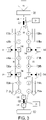
- FIG. 3 is an explanatory diagram showing an electric circuit of the coil 7.
- a circuit to which the coil 7 is connected in series is formed between the first and fourth segments 14, and a circuit to which the coil 7 is connected in series is formed between the seventh and tenth segments 14.
- These two circuits are connected in parallel.
- a current value supplied to the brush 22 is 4[i]
- currents supplied to each circuit each have a current value of 2[i].
- a current supplied to the equalizer 52 also has a current value of 2[i].
- the coil 7 wound around each tooth 50 can be connected to each segment 14. Hence, it can be prevented that the value of the current flowing through the coil 7 connecting the segments 14 having the same potential may increase.
- the winding operation of the coil 7 can be performed continuously in a single stroke.
- a winding device can be simplified and the winding operation of the coil 7 can be facilitated.
- the number of turns of the coil 7 can be reduced, and the amount of coating of the coil 7 can be reduced. As a result, it is possible to improve a space factor of the coil 7.
- the brushed motor 1 is used as the driving source for electrical equipment (for example, a power window) mounted on a vehicle.
- electrical equipment for example, a power window
- the present invention is not limited thereto, and the brushed motor 1 can be employed for driving various machines.
- a motor can be provided that can be reduced in size and that is capable of reducing a value of a current flowing through a connection line, simplifying a winding device, improving a space factor of a coil, and facilitating a winding operation.
Landscapes
- Engineering & Computer Science (AREA)
- Power Engineering (AREA)
- Manufacturing & Machinery (AREA)
- Dc Machiner (AREA)
- Windings For Motors And Generators (AREA)
Claims (1)
- Motor (1), umfassend:ein Joch (2) mit vier Magnetpolen (4);einen Ankerkern (6) mit einer rotierbaren Welle (5), die radial innerhalb des Jochs (2) vorgesehen ist, sechs Zähnen (50), die an der rotierbaren Welle (5) angebracht sind und sich radial nach außen erstrecken, und sechs Schlitzen (51), die zwischen jedem der Zähne (50) benachbart in einer Umfangsrichtung ausgebildet sind;eine Spule (7), die um jeden der Zähne (50) gewickelt ist;einen Kommutator (13), der benachbart zu dem Ankerkern (6) auf der rotierbaren Welle (5) vorgesehen ist und auf dem zwölf Segmente (14) in der Umfangsrichtung angeordnet sind; undeine Vielzahl von Bürsten (22), die die Spule (7) über jedes der Segmente (14) mit Energie versorgen, wobeiwenn die Zähne (50) in der Umfangsrichtung fortlaufend von 1 bis 6 nummeriert sind und die Segmente (14) in der Umfangsrichtung fortlaufend von 1 bis 12 nummeriert sind,ein Wicklungsanfangsanschluss (7a) der Spule (7) mit dem ersten Segment (14) verbunden ist und die Spule (7) istin einer Richtung in einer Rotationsrichtung der rotierbaren Welle (5) von dem ersten Segment (14) herumgezogen und um den fünften Zahn (50) in einer Vorwärtsrichtung gewickelt,von dem fünften Zahn (50) in der einen Richtung herumgezogen und um den zweiten Zahn (50) in der Vorwärtsrichtung gewickelt,in der einen Richtung vom zweiten Zahn (50) herumgezogen und mit dem zwölften Segment (14) verbunden,in der einen Richtung vom zwölften Segment (14) herumgezogen und mit dem sechsten Segment (14) verbunden,in der einen Richtung vom sechsten Segment (14) herumgezogen und um den sechsten Zahn (50) in einer der Vorwärtsrichtung entgegengesetzten Richtung gewickelt,in der einen Richtung vom sechsten Zahn (50) herumgezogen und in der entgegengesetzten Richtung um den dritten Zahn (50) gewickelt,in der einen Richtung vom dritten Zahn (50) herumgezogen und mit dem elften Segment (14) verbunden,in der einen Richtung vom elften Segment (14) herumgezogen und mit dem fünften Segment (14) verbunden,in der einen Richtung vom fünften Segment (14) herumgezogen und um den ersten Zahn (50) in der Vorwärtsrichtung gewickelt,in der einen Richtung vom ersten Zahn (50) herumgezogen und um den vierten Zahn (50) in der Vorwärtsrichtung gewickelt,in der einen Richtung vom vierten Zahn (50) herumgezogen und mit dem vierten Segment (14) verbunden,in der einen Richtung vom vierten Segment (14) herumgezogen und mit dem zehnten Segment (14) verbunden,in der einen Richtung vom zehnten Segment (14) herumgezogen und in der entgegengesetzten Richtung um den zweiten Zahn (50) gewickelt,in der einen Richtung vom zweiten Zahn (50) herumgezogen und in der entgegengesetzten Richtung um den fünften Zahn (50) gewickelt,in der einen Richtung von dem fünften Zahn (50) herumgezogen und mit dem dritten Segment (14) verbunden,in der einen Richtung vom dritten Segment (14) herumgezogen und mit dem neunten Segment (14) verbunden,in der einen Richtung vom neunten Segment (14) herumgezogen und um den dritten Zahn (50) in der Vorwärtsrichtung gewickelt,in der einen Richtung vom dritten Zahn (50) herumgezogen und um den sechsten Zahn (50) in der Vorwärtsrichtung gewickelt,in der einen Richtung vom sechsten Zahn (50) herumgezogen und mit dem achten Segment (14) verbunden,in der einen Richtung vom achten Segment (14) herumgezogen und mit dem zweiten Segment (14) verbunden,in der einen Richtung vom zweiten Segment (14) herumgezogen und in entgegengesetzten Richtung um den vierten Zahn (50) gewickelt,in der einen Richtung vom vierten Zahn (50) herumgezogen und in der entgegengesetzten Richtung um den ersten Zahn (50) gewickelt,in der einen Richtung von dem ersten Zahn (50) herumgezogen und mit dem siebten Segment (14) verbunden, undin der einen Richtung vom siebten Segment (14) herumgezogen und mit dem ersten Segment (14) verbunden.
Applications Claiming Priority (2)
| Application Number | Priority Date | Filing Date | Title |
|---|---|---|---|
| JP2018002168A JP6928563B2 (ja) | 2018-01-10 | 2018-01-10 | モータ |
| PCT/JP2018/040278 WO2019138662A1 (ja) | 2018-01-10 | 2018-10-30 | モータ |
Publications (3)
| Publication Number | Publication Date |
|---|---|
| EP3739735A1 EP3739735A1 (de) | 2020-11-18 |
| EP3739735A4 EP3739735A4 (de) | 2021-10-13 |
| EP3739735B1 true EP3739735B1 (de) | 2022-09-21 |
Family
ID=67218693
Family Applications (1)
| Application Number | Title | Priority Date | Filing Date |
|---|---|---|---|
| EP18899599.7A Active EP3739735B1 (de) | 2018-01-10 | 2018-10-30 | Motor |
Country Status (4)
| Country | Link |
|---|---|
| US (1) | US11043886B2 (de) |
| EP (1) | EP3739735B1 (de) |
| JP (1) | JP6928563B2 (de) |
| WO (1) | WO2019138662A1 (de) |
Families Citing this family (1)
| Publication number | Priority date | Publication date | Assignee | Title |
|---|---|---|---|---|
| EP3961881B1 (de) * | 2020-08-28 | 2026-04-15 | Brose Fahrzeugteile SE & Co. Kommanditgesellschaft, Coburg | Rotor für einen elektromotor |
Family Cites Families (10)
| Publication number | Priority date | Publication date | Assignee | Title |
|---|---|---|---|---|
| CN101297464B (zh) * | 2005-11-22 | 2011-08-24 | 株式会社美姿把 | 旋转电机中的电枢及其制造方法 |
| JP4886469B2 (ja) | 2006-10-30 | 2012-02-29 | 株式会社ミツバ | 直流モータのアーマチュア、直流モータ及び直流モータのアーマチュア巻線方法 |
| EP2302769A4 (de) * | 2008-06-30 | 2017-08-23 | Mitsuba Corporation | Elektromotor |
| JP5523318B2 (ja) * | 2008-07-22 | 2014-06-18 | 株式会社ミツバ | 3相直流モータ |
| CN201975875U (zh) * | 2011-01-27 | 2011-09-14 | 德昌电机(深圳)有限公司 | 电动工具及其永磁电机 |
| JP6141608B2 (ja) * | 2012-08-30 | 2017-06-07 | 株式会社ミツバ | 電動モータ |
| JP6316032B2 (ja) * | 2014-03-14 | 2018-04-25 | 株式会社ミツバ | 電動モータ |
| US20170324313A1 (en) * | 2014-06-19 | 2017-11-09 | Nidec Corporation | Motor |
| JP6579967B2 (ja) | 2016-01-20 | 2019-09-25 | 株式会社ミツバ | モータ |
| JP2018002168A (ja) | 2016-06-27 | 2018-01-11 | ライオン株式会社 | 容器のキャップ |
-
2018
- 2018-01-10 JP JP2018002168A patent/JP6928563B2/ja active Active
- 2018-10-30 WO PCT/JP2018/040278 patent/WO2019138662A1/ja not_active Ceased
- 2018-10-30 EP EP18899599.7A patent/EP3739735B1/de active Active
- 2018-10-30 US US16/648,239 patent/US11043886B2/en active Active
Also Published As
| Publication number | Publication date |
|---|---|
| US20200235648A1 (en) | 2020-07-23 |
| US11043886B2 (en) | 2021-06-22 |
| JP6928563B2 (ja) | 2021-09-01 |
| WO2019138662A1 (ja) | 2019-07-18 |
| JP2019122195A (ja) | 2019-07-22 |
| EP3739735A4 (de) | 2021-10-13 |
| EP3739735A1 (de) | 2020-11-18 |
Similar Documents
| Publication | Publication Date | Title |
|---|---|---|
| US8274193B2 (en) | Electric motor | |
| US8125117B2 (en) | Electric motor and rotor therefor | |
| JP5523318B2 (ja) | 3相直流モータ | |
| CN101584104B (zh) | 直流电动机的电枢、直流电动机以及直流电动机的电枢绕组方法 | |
| EP3116101A1 (de) | Ankerkern, anker und elektromotor | |
| EP3739735B1 (de) | Motor | |
| JP7074557B2 (ja) | 電動モータ | |
| JP6579967B2 (ja) | モータ | |
| JP2012196043A (ja) | 直流モータの巻線巻装方法、及び直流モータ | |
| JP6316032B2 (ja) | 電動モータ | |
| JP2010004597A (ja) | ブラシ付モータ | |
| JP5491588B2 (ja) | ブラシ付モータ | |
| JP2009240031A (ja) | 電動モータ | |
| JP5044360B2 (ja) | 電動モータ | |
| JP5714948B2 (ja) | 直流モータの巻線巻装方法、及び直流モータ | |
| JP5058753B2 (ja) | 電動モータ | |
| JP5980096B2 (ja) | 電動モータ | |
| JP6934373B2 (ja) | モータ | |
| JP2020058173A (ja) | アーマチュア、及び電動モータ | |
| JP2009303389A (ja) | ブラシ付モータ | |
| JP5491587B2 (ja) | 電動モータ | |
| WO2019049582A1 (ja) | モータ | |
| JP2019161727A (ja) | モータ | |
| WO2019039262A1 (ja) | 回転電機用インシュレータ及び回転電機 |
Legal Events
| Date | Code | Title | Description |
|---|---|---|---|
| STAA | Information on the status of an ep patent application or granted ep patent |
Free format text: STATUS: THE INTERNATIONAL PUBLICATION HAS BEEN MADE |
|
| PUAI | Public reference made under article 153(3) epc to a published international application that has entered the european phase |
Free format text: ORIGINAL CODE: 0009012 |
|
| STAA | Information on the status of an ep patent application or granted ep patent |
Free format text: STATUS: REQUEST FOR EXAMINATION WAS MADE |
|
| 17P | Request for examination filed |
Effective date: 20200310 |
|
| AK | Designated contracting states |
Kind code of ref document: A1 Designated state(s): AL AT BE BG CH CY CZ DE DK EE ES FI FR GB GR HR HU IE IS IT LI LT LU LV MC MK MT NL NO PL PT RO RS SE SI SK SM TR |
|
| AX | Request for extension of the european patent |
Extension state: BA ME |
|
| DAV | Request for validation of the european patent (deleted) | ||
| DAX | Request for extension of the european patent (deleted) | ||
| A4 | Supplementary search report drawn up and despatched |
Effective date: 20210914 |
|
| RIC1 | Information provided on ipc code assigned before grant |
Ipc: H02K 23/38 20060101ALN20210908BHEP Ipc: H02K 15/09 20060101ALI20210908BHEP Ipc: H02K 13/04 20060101ALI20210908BHEP Ipc: H02K 3/28 20060101ALI20210908BHEP Ipc: H02K 23/26 20060101AFI20210908BHEP |
|
| GRAP | Despatch of communication of intention to grant a patent |
Free format text: ORIGINAL CODE: EPIDOSNIGR1 |
|
| STAA | Information on the status of an ep patent application or granted ep patent |
Free format text: STATUS: GRANT OF PATENT IS INTENDED |
|
| RIC1 | Information provided on ipc code assigned before grant |
Ipc: H02K 23/38 20060101ALN20220504BHEP Ipc: H02K 15/09 20060101ALI20220504BHEP Ipc: H02K 13/04 20060101ALI20220504BHEP Ipc: H02K 3/28 20060101ALI20220504BHEP Ipc: H02K 23/26 20060101AFI20220504BHEP |
|
| INTG | Intention to grant announced |
Effective date: 20220601 |
|
| GRAS | Grant fee paid |
Free format text: ORIGINAL CODE: EPIDOSNIGR3 |
|
| GRAA | (expected) grant |
Free format text: ORIGINAL CODE: 0009210 |
|
| STAA | Information on the status of an ep patent application or granted ep patent |
Free format text: STATUS: THE PATENT HAS BEEN GRANTED |
|
| AK | Designated contracting states |
Kind code of ref document: B1 Designated state(s): AL AT BE BG CH CY CZ DE DK EE ES FI FR GB GR HR HU IE IS IT LI LT LU LV MC MK MT NL NO PL PT RO RS SE SI SK SM TR |
|
| REG | Reference to a national code |
Ref country code: GB Ref legal event code: FG4D |
|
| REG | Reference to a national code |
Ref country code: CH Ref legal event code: EP |
|
| REG | Reference to a national code |
Ref country code: IE Ref legal event code: FG4D |
|
| REG | Reference to a national code |
Ref country code: DE Ref legal event code: R096 Ref document number: 602018041005 Country of ref document: DE |
|
| REG | Reference to a national code |
Ref country code: AT Ref legal event code: REF Ref document number: 1520456 Country of ref document: AT Kind code of ref document: T Effective date: 20221015 |
|
| REG | Reference to a national code |
Ref country code: LT Ref legal event code: MG9D |
|
| REG | Reference to a national code |
Ref country code: NL Ref legal event code: MP Effective date: 20220921 |
|
| PG25 | Lapsed in a contracting state [announced via postgrant information from national office to epo] |
Ref country code: SE Free format text: LAPSE BECAUSE OF FAILURE TO SUBMIT A TRANSLATION OF THE DESCRIPTION OR TO PAY THE FEE WITHIN THE PRESCRIBED TIME-LIMIT Effective date: 20220921 Ref country code: RS Free format text: LAPSE BECAUSE OF FAILURE TO SUBMIT A TRANSLATION OF THE DESCRIPTION OR TO PAY THE FEE WITHIN THE PRESCRIBED TIME-LIMIT Effective date: 20220921 Ref country code: NO Free format text: LAPSE BECAUSE OF FAILURE TO SUBMIT A TRANSLATION OF THE DESCRIPTION OR TO PAY THE FEE WITHIN THE PRESCRIBED TIME-LIMIT Effective date: 20221221 Ref country code: LV Free format text: LAPSE BECAUSE OF FAILURE TO SUBMIT A TRANSLATION OF THE DESCRIPTION OR TO PAY THE FEE WITHIN THE PRESCRIBED TIME-LIMIT Effective date: 20220921 Ref country code: LT Free format text: LAPSE BECAUSE OF FAILURE TO SUBMIT A TRANSLATION OF THE DESCRIPTION OR TO PAY THE FEE WITHIN THE PRESCRIBED TIME-LIMIT Effective date: 20220921 Ref country code: FI Free format text: LAPSE BECAUSE OF FAILURE TO SUBMIT A TRANSLATION OF THE DESCRIPTION OR TO PAY THE FEE WITHIN THE PRESCRIBED TIME-LIMIT Effective date: 20220921 |
|
| REG | Reference to a national code |
Ref country code: AT Ref legal event code: MK05 Ref document number: 1520456 Country of ref document: AT Kind code of ref document: T Effective date: 20220921 |
|
| PG25 | Lapsed in a contracting state [announced via postgrant information from national office to epo] |
Ref country code: HR Free format text: LAPSE BECAUSE OF FAILURE TO SUBMIT A TRANSLATION OF THE DESCRIPTION OR TO PAY THE FEE WITHIN THE PRESCRIBED TIME-LIMIT Effective date: 20220921 Ref country code: GR Free format text: LAPSE BECAUSE OF FAILURE TO SUBMIT A TRANSLATION OF THE DESCRIPTION OR TO PAY THE FEE WITHIN THE PRESCRIBED TIME-LIMIT Effective date: 20221222 |
|
| PG25 | Lapsed in a contracting state [announced via postgrant information from national office to epo] |
Ref country code: SM Free format text: LAPSE BECAUSE OF FAILURE TO SUBMIT A TRANSLATION OF THE DESCRIPTION OR TO PAY THE FEE WITHIN THE PRESCRIBED TIME-LIMIT Effective date: 20220921 Ref country code: RO Free format text: LAPSE BECAUSE OF FAILURE TO SUBMIT A TRANSLATION OF THE DESCRIPTION OR TO PAY THE FEE WITHIN THE PRESCRIBED TIME-LIMIT Effective date: 20220921 Ref country code: PT Free format text: LAPSE BECAUSE OF FAILURE TO SUBMIT A TRANSLATION OF THE DESCRIPTION OR TO PAY THE FEE WITHIN THE PRESCRIBED TIME-LIMIT Effective date: 20230123 Ref country code: ES Free format text: LAPSE BECAUSE OF FAILURE TO SUBMIT A TRANSLATION OF THE DESCRIPTION OR TO PAY THE FEE WITHIN THE PRESCRIBED TIME-LIMIT Effective date: 20220921 Ref country code: CZ Free format text: LAPSE BECAUSE OF FAILURE TO SUBMIT A TRANSLATION OF THE DESCRIPTION OR TO PAY THE FEE WITHIN THE PRESCRIBED TIME-LIMIT Effective date: 20220921 Ref country code: AT Free format text: LAPSE BECAUSE OF FAILURE TO SUBMIT A TRANSLATION OF THE DESCRIPTION OR TO PAY THE FEE WITHIN THE PRESCRIBED TIME-LIMIT Effective date: 20220921 |
|
| PG25 | Lapsed in a contracting state [announced via postgrant information from national office to epo] |
Ref country code: SK Free format text: LAPSE BECAUSE OF FAILURE TO SUBMIT A TRANSLATION OF THE DESCRIPTION OR TO PAY THE FEE WITHIN THE PRESCRIBED TIME-LIMIT Effective date: 20220921 Ref country code: PL Free format text: LAPSE BECAUSE OF FAILURE TO SUBMIT A TRANSLATION OF THE DESCRIPTION OR TO PAY THE FEE WITHIN THE PRESCRIBED TIME-LIMIT Effective date: 20220921 Ref country code: IS Free format text: LAPSE BECAUSE OF FAILURE TO SUBMIT A TRANSLATION OF THE DESCRIPTION OR TO PAY THE FEE WITHIN THE PRESCRIBED TIME-LIMIT Effective date: 20230121 Ref country code: EE Free format text: LAPSE BECAUSE OF FAILURE TO SUBMIT A TRANSLATION OF THE DESCRIPTION OR TO PAY THE FEE WITHIN THE PRESCRIBED TIME-LIMIT Effective date: 20220921 |
|
| REG | Reference to a national code |
Ref country code: CH Ref legal event code: PL |
|
| REG | Reference to a national code |
Ref country code: DE Ref legal event code: R097 Ref document number: 602018041005 Country of ref document: DE |
|
| REG | Reference to a national code |
Ref country code: BE Ref legal event code: MM Effective date: 20221031 |
|
| PG25 | Lapsed in a contracting state [announced via postgrant information from national office to epo] |
Ref country code: NL Free format text: LAPSE BECAUSE OF FAILURE TO SUBMIT A TRANSLATION OF THE DESCRIPTION OR TO PAY THE FEE WITHIN THE PRESCRIBED TIME-LIMIT Effective date: 20220921 Ref country code: MC Free format text: LAPSE BECAUSE OF FAILURE TO SUBMIT A TRANSLATION OF THE DESCRIPTION OR TO PAY THE FEE WITHIN THE PRESCRIBED TIME-LIMIT Effective date: 20220921 Ref country code: LU Free format text: LAPSE BECAUSE OF NON-PAYMENT OF DUE FEES Effective date: 20221030 Ref country code: AL Free format text: LAPSE BECAUSE OF FAILURE TO SUBMIT A TRANSLATION OF THE DESCRIPTION OR TO PAY THE FEE WITHIN THE PRESCRIBED TIME-LIMIT Effective date: 20220921 |
|
| PLBE | No opposition filed within time limit |
Free format text: ORIGINAL CODE: 0009261 |
|
| STAA | Information on the status of an ep patent application or granted ep patent |
Free format text: STATUS: NO OPPOSITION FILED WITHIN TIME LIMIT |
|
| PG25 | Lapsed in a contracting state [announced via postgrant information from national office to epo] |
Ref country code: LI Free format text: LAPSE BECAUSE OF NON-PAYMENT OF DUE FEES Effective date: 20221031 Ref country code: DK Free format text: LAPSE BECAUSE OF FAILURE TO SUBMIT A TRANSLATION OF THE DESCRIPTION OR TO PAY THE FEE WITHIN THE PRESCRIBED TIME-LIMIT Effective date: 20220921 Ref country code: CH Free format text: LAPSE BECAUSE OF NON-PAYMENT OF DUE FEES Effective date: 20221031 |
|
| GBPC | Gb: european patent ceased through non-payment of renewal fee |
Effective date: 20221221 |
|
| 26N | No opposition filed |
Effective date: 20230622 |
|
| PG25 | Lapsed in a contracting state [announced via postgrant information from national office to epo] |
Ref country code: SI Free format text: LAPSE BECAUSE OF FAILURE TO SUBMIT A TRANSLATION OF THE DESCRIPTION OR TO PAY THE FEE WITHIN THE PRESCRIBED TIME-LIMIT Effective date: 20220921 |
|
| PG25 | Lapsed in a contracting state [announced via postgrant information from national office to epo] |
Ref country code: BE Free format text: LAPSE BECAUSE OF NON-PAYMENT OF DUE FEES Effective date: 20221031 |
|
| PG25 | Lapsed in a contracting state [announced via postgrant information from national office to epo] |
Ref country code: IE Free format text: LAPSE BECAUSE OF NON-PAYMENT OF DUE FEES Effective date: 20221030 Ref country code: GB Free format text: LAPSE BECAUSE OF NON-PAYMENT OF DUE FEES Effective date: 20221221 |
|
| PG25 | Lapsed in a contracting state [announced via postgrant information from national office to epo] |
Ref country code: FR Free format text: LAPSE BECAUSE OF NON-PAYMENT OF DUE FEES Effective date: 20221121 |
|
| PG25 | Lapsed in a contracting state [announced via postgrant information from national office to epo] |
Ref country code: CY Free format text: LAPSE BECAUSE OF FAILURE TO SUBMIT A TRANSLATION OF THE DESCRIPTION OR TO PAY THE FEE WITHIN THE PRESCRIBED TIME-LIMIT Effective date: 20220921 |
|
| PG25 | Lapsed in a contracting state [announced via postgrant information from national office to epo] |
Ref country code: MK Free format text: LAPSE BECAUSE OF FAILURE TO SUBMIT A TRANSLATION OF THE DESCRIPTION OR TO PAY THE FEE WITHIN THE PRESCRIBED TIME-LIMIT Effective date: 20220921 Ref country code: IT Free format text: LAPSE BECAUSE OF FAILURE TO SUBMIT A TRANSLATION OF THE DESCRIPTION OR TO PAY THE FEE WITHIN THE PRESCRIBED TIME-LIMIT Effective date: 20220921 Ref country code: HU Free format text: LAPSE BECAUSE OF FAILURE TO SUBMIT A TRANSLATION OF THE DESCRIPTION OR TO PAY THE FEE WITHIN THE PRESCRIBED TIME-LIMIT; INVALID AB INITIO Effective date: 20181030 |
|
| PG25 | Lapsed in a contracting state [announced via postgrant information from national office to epo] |
Ref country code: TR Free format text: LAPSE BECAUSE OF FAILURE TO SUBMIT A TRANSLATION OF THE DESCRIPTION OR TO PAY THE FEE WITHIN THE PRESCRIBED TIME-LIMIT Effective date: 20220921 |
|
| PG25 | Lapsed in a contracting state [announced via postgrant information from national office to epo] |
Ref country code: BG Free format text: LAPSE BECAUSE OF FAILURE TO SUBMIT A TRANSLATION OF THE DESCRIPTION OR TO PAY THE FEE WITHIN THE PRESCRIBED TIME-LIMIT Effective date: 20220921 |
|
| PG25 | Lapsed in a contracting state [announced via postgrant information from national office to epo] |
Ref country code: MT Free format text: LAPSE BECAUSE OF FAILURE TO SUBMIT A TRANSLATION OF THE DESCRIPTION OR TO PAY THE FEE WITHIN THE PRESCRIBED TIME-LIMIT Effective date: 20220921 |
|
| PGFP | Annual fee paid to national office [announced via postgrant information from national office to epo] |
Ref country code: DE Payment date: 20250902 Year of fee payment: 8 |