EP3739906B1 - Instrument auditif - Google Patents
Instrument auditif Download PDFInfo
- Publication number
- EP3739906B1 EP3739906B1 EP20159933.9A EP20159933A EP3739906B1 EP 3739906 B1 EP3739906 B1 EP 3739906B1 EP 20159933 A EP20159933 A EP 20159933A EP 3739906 B1 EP3739906 B1 EP 3739906B1
- Authority
- EP
- European Patent Office
- Prior art keywords
- battery
- hearing instrument
- coil
- hearing
- connection contacts
- Prior art date
- Legal status (The legal status is an assumption and is not a legal conclusion. Google has not performed a legal analysis and makes no representation as to the accuracy of the status listed.)
- Active
Links
Images

Classifications
-
- B—PERFORMING OPERATIONS; TRANSPORTING
- B60—VEHICLES IN GENERAL
- B60T—VEHICLE BRAKE CONTROL SYSTEMS OR PARTS THEREOF; BRAKE CONTROL SYSTEMS OR PARTS THEREOF, IN GENERAL; ARRANGEMENT OF BRAKING ELEMENTS ON VEHICLES IN GENERAL; PORTABLE DEVICES FOR PREVENTING UNWANTED MOVEMENT OF VEHICLES; VEHICLE MODIFICATIONS TO FACILITATE COOLING OF BRAKES
- B60T13/00—Transmitting braking action from initiating means to ultimate brake actuator with power assistance or drive; Brake systems incorporating such transmitting means, e.g. air-pressure brake systems
- B60T13/74—Transmitting braking action from initiating means to ultimate brake actuator with power assistance or drive; Brake systems incorporating such transmitting means, e.g. air-pressure brake systems with electrical assistance or drive
- B60T13/745—Transmitting braking action from initiating means to ultimate brake actuator with power assistance or drive; Brake systems incorporating such transmitting means, e.g. air-pressure brake systems with electrical assistance or drive acting on a hydraulic system, e.g. a master cylinder
-
- H—ELECTRICITY
- H04—ELECTRIC COMMUNICATION TECHNIQUE
- H04R—LOUDSPEAKERS, MICROPHONES, GRAMOPHONE PICK-UPS OR LIKE ACOUSTIC ELECTROMECHANICAL TRANSDUCERS; ELECTRIC HEARING AIDS; PUBLIC ADDRESS SYSTEMS
- H04R25/00—Electric hearing aids
- H04R25/65—Housing parts, e.g. shells, tips or moulds, or their manufacture
-
- B—PERFORMING OPERATIONS; TRANSPORTING
- B60—VEHICLES IN GENERAL
- B60T—VEHICLE BRAKE CONTROL SYSTEMS OR PARTS THEREOF; BRAKE CONTROL SYSTEMS OR PARTS THEREOF, IN GENERAL; ARRANGEMENT OF BRAKING ELEMENTS ON VEHICLES IN GENERAL; PORTABLE DEVICES FOR PREVENTING UNWANTED MOVEMENT OF VEHICLES; VEHICLE MODIFICATIONS TO FACILITATE COOLING OF BRAKES
- B60T13/00—Transmitting braking action from initiating means to ultimate brake actuator with power assistance or drive; Brake systems incorporating such transmitting means, e.g. air-pressure brake systems
- B60T13/10—Transmitting braking action from initiating means to ultimate brake actuator with power assistance or drive; Brake systems incorporating such transmitting means, e.g. air-pressure brake systems with fluid assistance, drive, or release
- B60T13/12—Transmitting braking action from initiating means to ultimate brake actuator with power assistance or drive; Brake systems incorporating such transmitting means, e.g. air-pressure brake systems with fluid assistance, drive, or release the fluid being liquid
- B60T13/14—Transmitting braking action from initiating means to ultimate brake actuator with power assistance or drive; Brake systems incorporating such transmitting means, e.g. air-pressure brake systems with fluid assistance, drive, or release the fluid being liquid using accumulators or reservoirs fed by pumps
- B60T13/142—Systems with master cylinder
-
- B—PERFORMING OPERATIONS; TRANSPORTING
- B60—VEHICLES IN GENERAL
- B60T—VEHICLE BRAKE CONTROL SYSTEMS OR PARTS THEREOF; BRAKE CONTROL SYSTEMS OR PARTS THEREOF, IN GENERAL; ARRANGEMENT OF BRAKING ELEMENTS ON VEHICLES IN GENERAL; PORTABLE DEVICES FOR PREVENTING UNWANTED MOVEMENT OF VEHICLES; VEHICLE MODIFICATIONS TO FACILITATE COOLING OF BRAKES
- B60T13/00—Transmitting braking action from initiating means to ultimate brake actuator with power assistance or drive; Brake systems incorporating such transmitting means, e.g. air-pressure brake systems
- B60T13/10—Transmitting braking action from initiating means to ultimate brake actuator with power assistance or drive; Brake systems incorporating such transmitting means, e.g. air-pressure brake systems with fluid assistance, drive, or release
- B60T13/66—Electrical control in fluid-pressure brake systems
- B60T13/68—Electrical control in fluid-pressure brake systems by electrically-controlled valves
- B60T13/686—Electrical control in fluid-pressure brake systems by electrically-controlled valves in hydraulic systems or parts thereof
-
- H—ELECTRICITY
- H01—ELECTRIC ELEMENTS
- H01M—PROCESSES OR MEANS, e.g. BATTERIES, FOR THE DIRECT CONVERSION OF CHEMICAL ENERGY INTO ELECTRICAL ENERGY
- H01M10/00—Secondary cells; Manufacture thereof
- H01M10/05—Accumulators with non-aqueous electrolyte
- H01M10/052—Li-accumulators
- H01M10/0525—Rocking-chair batteries, i.e. batteries with lithium insertion or intercalation in both electrodes; Lithium-ion batteries
-
- H—ELECTRICITY
- H01—ELECTRIC ELEMENTS
- H01M—PROCESSES OR MEANS, e.g. BATTERIES, FOR THE DIRECT CONVERSION OF CHEMICAL ENERGY INTO ELECTRICAL ENERGY
- H01M10/00—Secondary cells; Manufacture thereof
- H01M10/42—Methods or arrangements for servicing or maintenance of secondary cells or secondary half-cells
- H01M10/425—Structural combination with electronic components, e.g. electronic circuits integrated to the outside of the casing
-
- H—ELECTRICITY
- H01—ELECTRIC ELEMENTS
- H01M—PROCESSES OR MEANS, e.g. BATTERIES, FOR THE DIRECT CONVERSION OF CHEMICAL ENERGY INTO ELECTRICAL ENERGY
- H01M10/00—Secondary cells; Manufacture thereof
- H01M10/42—Methods or arrangements for servicing or maintenance of secondary cells or secondary half-cells
- H01M10/46—Accumulators structurally combined with charging apparatus
-
- H—ELECTRICITY
- H01—ELECTRIC ELEMENTS
- H01M—PROCESSES OR MEANS, e.g. BATTERIES, FOR THE DIRECT CONVERSION OF CHEMICAL ENERGY INTO ELECTRICAL ENERGY
- H01M50/00—Constructional details or processes of manufacture of the non-active parts of electrochemical cells other than fuel cells, e.g. hybrid cells
- H01M50/20—Mountings; Secondary casings or frames; Racks, modules or packs; Suspension devices; Shock absorbers; Transport or carrying devices; Holders
- H01M50/204—Racks, modules or packs for multiple batteries or multiple cells
- H01M50/207—Racks, modules or packs for multiple batteries or multiple cells characterised by their shape
- H01M50/213—Racks, modules or packs for multiple batteries or multiple cells characterised by their shape adapted for cells having curved cross-section, e.g. round or elliptic
-
- H—ELECTRICITY
- H01—ELECTRIC ELEMENTS
- H01M—PROCESSES OR MEANS, e.g. BATTERIES, FOR THE DIRECT CONVERSION OF CHEMICAL ENERGY INTO ELECTRICAL ENERGY
- H01M50/00—Constructional details or processes of manufacture of the non-active parts of electrochemical cells other than fuel cells, e.g. hybrid cells
- H01M50/20—Mountings; Secondary casings or frames; Racks, modules or packs; Suspension devices; Shock absorbers; Transport or carrying devices; Holders
- H01M50/247—Mountings; Secondary casings or frames; Racks, modules or packs; Suspension devices; Shock absorbers; Transport or carrying devices; Holders specially adapted for portable devices, e.g. mobile phones, computers, hand tools or pacemakers
-
- H—ELECTRICITY
- H04—ELECTRIC COMMUNICATION TECHNIQUE
- H04R—LOUDSPEAKERS, MICROPHONES, GRAMOPHONE PICK-UPS OR LIKE ACOUSTIC ELECTROMECHANICAL TRANSDUCERS; ELECTRIC HEARING AIDS; PUBLIC ADDRESS SYSTEMS
- H04R25/00—Electric hearing aids
- H04R25/35—Electric hearing aids using translation techniques
- H04R25/353—Frequency, e.g. frequency shift or compression
-
- H—ELECTRICITY
- H04—ELECTRIC COMMUNICATION TECHNIQUE
- H04R—LOUDSPEAKERS, MICROPHONES, GRAMOPHONE PICK-UPS OR LIKE ACOUSTIC ELECTROMECHANICAL TRANSDUCERS; ELECTRIC HEARING AIDS; PUBLIC ADDRESS SYSTEMS
- H04R25/00—Electric hearing aids
- H04R25/55—Electric hearing aids using an external connection, either wireless or wired
- H04R25/554—Electric hearing aids using an external connection, either wireless or wired using a wireless connection, e.g. between microphone and amplifier or using Tcoils
-
- H—ELECTRICITY
- H04—ELECTRIC COMMUNICATION TECHNIQUE
- H04R—LOUDSPEAKERS, MICROPHONES, GRAMOPHONE PICK-UPS OR LIKE ACOUSTIC ELECTROMECHANICAL TRANSDUCERS; ELECTRIC HEARING AIDS; PUBLIC ADDRESS SYSTEMS
- H04R25/00—Electric hearing aids
- H04R25/60—Mounting or interconnection of hearing aid parts, e.g. inside tips, housings or to ossicles
- H04R25/602—Mounting or interconnection of hearing aid parts, e.g. inside tips, housings or to ossicles of batteries
-
- H—ELECTRICITY
- H04—ELECTRIC COMMUNICATION TECHNIQUE
- H04R—LOUDSPEAKERS, MICROPHONES, GRAMOPHONE PICK-UPS OR LIKE ACOUSTIC ELECTROMECHANICAL TRANSDUCERS; ELECTRIC HEARING AIDS; PUBLIC ADDRESS SYSTEMS
- H04R25/00—Electric hearing aids
- H04R25/60—Mounting or interconnection of hearing aid parts, e.g. inside tips, housings or to ossicles
- H04R25/604—Mounting or interconnection of hearing aid parts, e.g. inside tips, housings or to ossicles of acoustic or vibrational transducers
-
- H—ELECTRICITY
- H04—ELECTRIC COMMUNICATION TECHNIQUE
- H04R—LOUDSPEAKERS, MICROPHONES, GRAMOPHONE PICK-UPS OR LIKE ACOUSTIC ELECTROMECHANICAL TRANSDUCERS; ELECTRIC HEARING AIDS; PUBLIC ADDRESS SYSTEMS
- H04R25/00—Electric hearing aids
- H04R25/60—Mounting or interconnection of hearing aid parts, e.g. inside tips, housings or to ossicles
- H04R25/609—Mounting or interconnection of hearing aid parts, e.g. inside tips, housings or to ossicles of circuitry
-
- H—ELECTRICITY
- H04—ELECTRIC COMMUNICATION TECHNIQUE
- H04R—LOUDSPEAKERS, MICROPHONES, GRAMOPHONE PICK-UPS OR LIKE ACOUSTIC ELECTROMECHANICAL TRANSDUCERS; ELECTRIC HEARING AIDS; PUBLIC ADDRESS SYSTEMS
- H04R9/00—Transducers of moving-coil, moving-strip, or moving-wire type
- H04R9/02—Details
- H04R9/04—Construction, mounting, or centering of coil
- H04R9/045—Mounting
-
- H—ELECTRICITY
- H04—ELECTRIC COMMUNICATION TECHNIQUE
- H04R—LOUDSPEAKERS, MICROPHONES, GRAMOPHONE PICK-UPS OR LIKE ACOUSTIC ELECTROMECHANICAL TRANSDUCERS; ELECTRIC HEARING AIDS; PUBLIC ADDRESS SYSTEMS
- H04R9/00—Transducers of moving-coil, moving-strip, or moving-wire type
- H04R9/06—Loudspeakers
-
- H—ELECTRICITY
- H04—ELECTRIC COMMUNICATION TECHNIQUE
- H04R—LOUDSPEAKERS, MICROPHONES, GRAMOPHONE PICK-UPS OR LIKE ACOUSTIC ELECTROMECHANICAL TRANSDUCERS; ELECTRIC HEARING AIDS; PUBLIC ADDRESS SYSTEMS
- H04R9/00—Transducers of moving-coil, moving-strip, or moving-wire type
- H04R9/08—Microphones
-
- H—ELECTRICITY
- H01—ELECTRIC ELEMENTS
- H01M—PROCESSES OR MEANS, e.g. BATTERIES, FOR THE DIRECT CONVERSION OF CHEMICAL ENERGY INTO ELECTRICAL ENERGY
- H01M2220/00—Batteries for particular applications
- H01M2220/30—Batteries in portable systems, e.g. mobile phone, laptop
-
- H—ELECTRICITY
- H04—ELECTRIC COMMUNICATION TECHNIQUE
- H04R—LOUDSPEAKERS, MICROPHONES, GRAMOPHONE PICK-UPS OR LIKE ACOUSTIC ELECTROMECHANICAL TRANSDUCERS; ELECTRIC HEARING AIDS; PUBLIC ADDRESS SYSTEMS
- H04R2225/00—Details of deaf aids covered by H04R25/00, not provided for in any of its subgroups
- H04R2225/021—Behind the ear [BTE] hearing aids
-
- H—ELECTRICITY
- H04—ELECTRIC COMMUNICATION TECHNIQUE
- H04R—LOUDSPEAKERS, MICROPHONES, GRAMOPHONE PICK-UPS OR LIKE ACOUSTIC ELECTROMECHANICAL TRANSDUCERS; ELECTRIC HEARING AIDS; PUBLIC ADDRESS SYSTEMS
- H04R2225/00—Details of deaf aids covered by H04R25/00, not provided for in any of its subgroups
- H04R2225/025—In the ear hearing aids [ITE] hearing aids
-
- H—ELECTRICITY
- H04—ELECTRIC COMMUNICATION TECHNIQUE
- H04R—LOUDSPEAKERS, MICROPHONES, GRAMOPHONE PICK-UPS OR LIKE ACOUSTIC ELECTROMECHANICAL TRANSDUCERS; ELECTRIC HEARING AIDS; PUBLIC ADDRESS SYSTEMS
- H04R2225/00—Details of deaf aids covered by H04R25/00, not provided for in any of its subgroups
- H04R2225/31—Aspects of the use of accumulators in hearing aids, e.g. rechargeable batteries or fuel cells
-
- H—ELECTRICITY
- H04—ELECTRIC COMMUNICATION TECHNIQUE
- H04R—LOUDSPEAKERS, MICROPHONES, GRAMOPHONE PICK-UPS OR LIKE ACOUSTIC ELECTROMECHANICAL TRANSDUCERS; ELECTRIC HEARING AIDS; PUBLIC ADDRESS SYSTEMS
- H04R2225/00—Details of deaf aids covered by H04R25/00, not provided for in any of its subgroups
- H04R2225/43—Signal processing in hearing aids to enhance the speech intelligibility
-
- H—ELECTRICITY
- H04—ELECTRIC COMMUNICATION TECHNIQUE
- H04R—LOUDSPEAKERS, MICROPHONES, GRAMOPHONE PICK-UPS OR LIKE ACOUSTIC ELECTROMECHANICAL TRANSDUCERS; ELECTRIC HEARING AIDS; PUBLIC ADDRESS SYSTEMS
- H04R2225/00—Details of deaf aids covered by H04R25/00, not provided for in any of its subgroups
- H04R2225/51—Aspects of antennas or their circuitry in or for hearing aids
-
- Y—GENERAL TAGGING OF NEW TECHNOLOGICAL DEVELOPMENTS; GENERAL TAGGING OF CROSS-SECTIONAL TECHNOLOGIES SPANNING OVER SEVERAL SECTIONS OF THE IPC; TECHNICAL SUBJECTS COVERED BY FORMER USPC CROSS-REFERENCE ART COLLECTIONS [XRACs] AND DIGESTS
- Y02—TECHNOLOGIES OR APPLICATIONS FOR MITIGATION OR ADAPTATION AGAINST CLIMATE CHANGE
- Y02E—REDUCTION OF GREENHOUSE GAS [GHG] EMISSIONS, RELATED TO ENERGY GENERATION, TRANSMISSION OR DISTRIBUTION
- Y02E60/00—Enabling technologies; Technologies with a potential or indirect contribution to GHG emissions mitigation
- Y02E60/10—Energy storage using batteries
Definitions
- the invention relates to a hearing instrument according to the preamble of claim 1, with a rechargeable battery and a (magnetically) inductive transmitting and/or receiving coil.
- a “hearing instrument” is generally a device that picks up ambient sound, modifies it in terms of signal technology and emits a modified sound signal to the ears of a person wearing the hearing instrument ("wearer").
- a hearing instrument that is designed to supply a hearing-impaired wearer and that processes, in particular amplifies, acoustic ambient signals in such a way that the hearing impairment is fully or partially compensated is referred to here and below as a “hearing aid”.
- a hearing aid usually comprises an input converter, for example in the form of a microphone, a signal processing unit with an amplifier, and an output converter.
- the output converter is usually implemented as a miniature loudspeaker and is also referred to as a "receiver”.
- hearing instruments that are designed for people with normal hearing in order to protect the hearing of the wearer or to support sound perception (e.g. understanding speech in complex noise environments) for certain purposes.
- Such hearing instruments are often constructed in a similar way to hearing aids and in particular also include the above-mentioned components of input transducer, signal processing and output transducer.
- a housing equipped with the input transducer, signal processing and a battery is worn behind the ear.
- the output transducer can be located directly in the wearer's ear canal (so-called ex-receiver hearing instruments or receiver-in-the-canal, RIC for short).
- the output transducer is located within the housing itself.
- a flexible sound tube also known as a "tube” conducts the acoustic output signals of the output transducer from the housing to the ear canal (sound tube hearing instruments).
- ITE hearing instruments In-the-Ear, IdO for short
- CIC Compactly-in-Canal
- hearing instruments Due to the increasing number of integrated functions, hearing instruments have an increasing energy requirement that cannot be satisfactorily covered by today's disposable batteries.
- the aim is therefore to use powerful rechargeable batteries, in particular lithium-ion batteries (Li-ion batteries for short), as a power source for hearing instruments.
- rechargeable batteries generate parasitic magnetic fields and can therefore interfere with the inductive transmitting and/or receiving coils (e.g. telephone coils or inductive transceivers for wireless communication between the hearing instrument and a peripheral device) that are often integrated in hearing instruments, in particular hearing aids.
- the simultaneous and interference-free arrangement of a rechargeable battery and an inductive transmitting and/or receiving coil in a hearing instrument housing is therefore complicated and in many cases even impossible - given the extremely limited space in the housing of a hearing instrument.
- a hearing instrument according to the preamble of claim 1 is made of US 2016/0365751 A1 known.
- the invention is based on the object of realizing a compact arrangement of both a powerful rechargeable battery and an inductive transmitting and/or receiving coil in a hearing instrument, wherein an undesirable influence of the transmitting and/or receiving coil by the battery is to be prevented or at least largely reduced.
- the hearing instrument has a rechargeable battery on the one hand and an inductive transmitting and/or receiving coil on the other hand (hereinafter referred to as coil).
- the battery is designed in the so-called stack construction, i.e. as a layered stack.
- the battery designed in the stack construction comprises a plurality of layers that are stacked on top of one another in a layering direction (or stacking direction).
- the layering plane (or stacking plane) is a plane that is aligned orthogonally (i.e. at a right angle) to the layering direction. This layering plane is parallel to the interfaces at which adjacent layers of the battery designed in the stack construction abut one another.
- the coil is arranged in such a way that its axis is orthogonal to the layering direction (i.e. parallel to a layering plane) of the battery. This ensures that the parasitic magnetic fields generated by the battery during operation of the hearing instrument do not interfere with the coil or only interfere with it to a very small extent. This in turn enables a particularly compact arrangement of the battery and the coil in a housing of the hearing instrument.
- the coil can be arranged particularly close to the battery without the function of the coil being interfered with by the battery. Magnetic shielding of the coil from the battery is - depending on the design - either completely unnecessary and therefore not present or can at least be designed to be comparatively simple.
- the battery is preferably in the form of a Li-ion battery.
- the coil is in particular a telephone coil (telecoil) or an inductive transceiver.
- Telephone coils are designed to receive alternating magnetic fields in the typical frequency range of audible sound waves (e.g. approx. 100 Hz to 10 kHz) and are used to receive acoustic information that has been converted directly into alternating magnetic fields (e.g. by induction loops installed in churches or museums).
- Inductive transceivers are designed to send and/or receive alternating magnetic fields of higher frequencies, typically in the megahertz range. They are typically used for wireless information transmission between the hearing instrument and a peripheral device, e.g. another hearing instrument to supply the wearer's other ear, a remote control, an external audio interface device or an external microphone.
- the coil can also be a component of a magnetic sensor, such as an electronic compass.
- the battery is arranged in the housing of the hearing aid in such a way that the layering direction of the battery is aligned approximately in the direction of view of the wearer when the hearing instrument is worn in the intended position in or on the ear.
- the wearer's viewing direction is defined as the direction of view - regardless of from the position of the wearer's eyes - refers to the direction in the plane of symmetry of the head, which is horizontal when the head is held straight, and which is therefore also aligned orthogonally to the transverse direction of the head (i.e. the straight connection between the wearer's ears).
- This alignment of the battery is particularly advantageous, especially as it allows a favorable, but at the same time interference-proof arrangement of the coil.
- the coil is arranged in particular in such a way that its axis is aligned both orthogonally to the layering direction and vertically in the surrounding space (i.e. at a right angle to the ground) in the intended wearing position of the hearing instrument in or on the ear.
- the vertical alignment of the coil axis enables particularly good reception, in particular when the coil is designed as a telephone coil.
- the coil is arranged in such a way that its axis is aligned both orthogonally to the layering direction and parallel to the transverse direction of the head in the intended wearing position of the hearing instrument in or on the ear.
- the alignment of the coil axis in the transverse direction enables particularly efficient signal transmission, in particular when the coil is designed as an inductive transceiver and is used to exchange signals with another hearing instrument worn on the wearer's other ear.
- the battery has two electrical connection contacts (battery poles) in a practical embodiment.
- the structural unit formed from the two connection contacts is also referred to below as a "contact arrangement".
- the two connection contacts are arranged at a distance from one another that is small compared to the longitudinal extent of the battery.
- the longitudinal extent is understood here to be the size of the longest edge or dimension of the battery.
- the distance between the two termination contacts is at most one third, preferably at most one quarter, of the longitudinal extent of the battery.
- the two connection contacts are arranged next to one another parallel to the axis of the coil (ie along a line parallel to the axis of the coil).
- the coil is further preferably positioned - viewed transversely to its axis - centered with the contact arrangement, namely in particular such that a geometric center of the coil is arranged equidistant from both connection contacts of the battery.
- the coil is arranged near a bottom of the battery, i.e. near a side of the battery facing away from the terminating contacts, since here the current density within the battery and thus also the influence of the battery on the coil are particularly low.
- the battery generally has the shape of a straight mathematical cylinder with polygonal end faces and at least one side wall perpendicular thereto. The end faces are aligned perpendicular to the layering direction (parallel to the layering plane).
- the battery has the shape of a cuboid (which in this respect forms a special form of the above-mentioned straight mathematical cylinder).
- the battery has two end faces that are opposite one another in the layering direction of the battery, two wide sides that are opposite one another (perpendicular to the end faces) and two narrow sides that are opposite one another (perpendicular to the end faces and the wide sides).
- the cuboid design of the battery has the particular advantage that it allows a comparatively large number of battery layers to be accommodated in a flat battery housing that can be integrated particularly well (i.e. in a space-optimized manner) into the housing of the hearing instrument.
- the two connection contacts are preferably arranged on one of the two end faces. In other words, both termination contacts are arranged on the same front side.
- the coil is arranged adjacent to the side wall (or one of several side walls) of the battery.
- each of the two connection contacts is arranged on the edge of an associated front side facing away from the battery.
- the connection contacts are therefore particularly far away from the coil, which further reduces the likelihood of the battery interfering with the coil.
- the coil is preferably arranged adjacent to a narrow side of the battery, as this is particularly advantageous for reasons of space optimization and because it also allows the coil to be arranged at a particularly large distance from the battery's connection contacts.
- This arrangement is particularly advantageous for comparatively small coils, e.g. inductive transceivers.
- an alternative embodiment of the invention is preferred for reasons of space optimization, in which the coil is arranged adjacent to one of the two broad sides of the cuboid-shaped battery.
- the coil is preferably positioned - seen transversely to its axis - centered on the broad side of the battery.
- the invention described above is preferably used in a BTE hearing instrument.
- the battery and the coil are arranged in a housing that is worn behind the wearer's ear.
- the invention can also be used in hearing instruments of a different design, in particular ITE hearing instruments or (fully or partially) implanted hearing instruments.
- the hearing instrument is in particular a hearing aid - constructed as described above - for supplying a hearing-impaired wearer.
- the hearing instrument preferably has at least one input converter (for example in the form of a microphone), a signal processing unit with a (particularly digital) signal processor and/or an amplifier and an output converter (particularly a receiver).
- the output converter is optionally integrated into the housing or arranged in an earpiece separate from the housing.
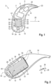
- FIG.1 A hearing instrument 2 in the form of a (BTE) hearing aid is shown roughly schematically.
- the hearing instrument 2 comprises a housing 4 to be worn behind the ear of a hearing-impaired wearer, in which the main components are two input converters 6 in the form of microphones, a signal processing unit 8 with a digital signal processor and/or a microcontroller, an output converter 10 in the form of a receiver and a rechargeable battery 12.
- the battery 12 is a Li-ion battery.
- the hearing instrument 2 also comprises a (magnetic) inductive coil 14 for sending and/or receiving magnetic alternating signals.
- a large part of the electrical and electronic components of the hearing instrument 2, in particular the input transducer 6, the signal processing unit 8 and the output transducer 8, are mounted on an electronics frame 16.
- the electronics frame 16 is a framework manufactured separately from the housing 4, in particular from plastic, on which the aforementioned electrical and electronic components can be pre-assembled outside the housing 4.
- the battery 12 and/or the coil 14 are preferably also fastened in or to the electronics frame 16.
- the battery 12 and the coil 14 are inserted into a recess 18 of the electronics frame 16 such that the battery 12 and the coil 14 are fixed in a defined relative position to one another and to the housing 4.
- a sound signal from the environment of the hearing instrument 2 is recorded by means of the input transducer 6 and output to the signal processing unit 8 as an audio signal (i.e. as an electrical signal carrying sound information).
- the recorded audio signal is processed by the signal processing unit 8, in particular amplified in a frequency-dependent manner in order to compensate for the wearer's hearing impairment.
- the signal processing unit 8 outputs a modified audio signal resulting from this processing to the output transducer 10. This in turn converts the modified audio signal into a sound signal.
- This sound signal (modified compared to the sound recorded from the environment) is first transmitted by the output transducer 10 through a sound channel 20 to a tip 22 of the housing. 4, and from there through a sound tube not explicitly shown into the wearer’s ear.
- the coil 14 is designed as an inductive transceiver for exchanging data with a second hearing instrument, whereby this second hearing instrument is worn on the other ear of the wearer.
- the coil 14 is designed for this purpose for sending and receiving magnetic alternating signals in the megahertz range (eg with a frequency of 3.3 MHz).
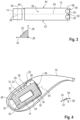
- the battery 12 is constructed in a stack design, ie as a layer stack 24. It therefore comprises a plurality of active layers 26 which are stacked on top of one another in a layering direction 28.
- the layers 26 of the battery 12 lie against one another at interfaces 30 which are parallel to a (eg in the Fig.2 and 3 shown) layering plane 32.
- This layering plane 32 is orthogonal to the layering direction 28 and is arranged in a Fig.2 and 3
- the coordinate system shown is spanned by two directions orthogonal to each other and to the layering direction 28, namely a longitudinal direction 34 and a transverse direction 36.
- the battery 12 has the shape of a cuboid with two end faces 38 and 40, which are opposite each other in the layering direction 28.
- the two end faces 38 and 40 are each aligned orthogonally to the layering direction 28 (thus parallel to the layering plane 32) and are separated by four side walls, namely two opposing broad sides 42 and 44 ( Fig.3 ) and two opposite narrow sides 46 and 48.
- the battery 12 has two electrical connection contacts 50, both of which are arranged next to each other on the front side 38.
- the assembly formed by the connection contacts 50 is also referred to collectively as contact arrangement 52 ( Fig.2 ).
- the connection contacts 50 are arranged on an edge of the front side 38, which borders on the narrow side 46 facing the tip 22 of the housing 4.
- the coil 14 is arranged adjacent to the narrow side 48 of the battery 12 facing away from the tip 22 of the housing 4. The coil 14 is thus comparatively far away from the connection contacts 50 of the battery 12.
- the coil 14 is oriented such that its axis 54 ( Fig.3 ) parallel to the transverse direction 36, and thus orthogonal to the layering direction 28 (hence parallel to the layering plane 32).
- connection contacts 50 are arranged at a distance from each other that is small compared to the longitudinal extension of the battery 12 - in the example according to Fig. 1 to 3 the distance between the connection contacts 50 measured along a connecting line 56 corresponds to only about one seventh of the longitudinal extent of the battery 12, which here is formed by the length of the edge of the battery 12 running in the longitudinal direction 34.
- the two connection contacts 50 are arranged next to one another parallel to the axis 54 of the coil 14.
- the connecting line 56 between the connection contacts 50 is aligned parallel to the axis 54 of the coil 14.
- the coil 14 - seen transversely to its axis 54 - is positioned centered with the contact arrangement 52, i.e.
- the coil 14 is arranged such that it is arranged orthogonally and centered to the parasitic magnetic fields caused by circulating currents in the battery 12, whereby interactions of these magnetic fields with the coil 14 are excluded or at least largely reduced.
- the battery 12 is aligned such that its layering direction 28 is aligned exactly or at least approximately parallel to the direction of view of the wearer.
- the axis 54 of the coil 14, which is perpendicular to this, is aligned exactly or at least approximately in the transverse direction of the head, and thus to the second hearing instrument worn on the other ear of the wearer. This ensures effective data transmission between the two hearing instruments.
- a second embodiment of the hearing instrument 2 is shown, in which the coil 14 is designed as a telephone coil. Due to the significantly larger size of the coil 14 here and due to the desired orientation of the coil 14 in the wearing position of the hearing instrument 2, the coil 14 in the example according to Fig.4 and 5 adjacent to the broad side 44 of the battery 12. As in the previous example, the axis 54 of the coil 14 is aligned orthogonally to the layering direction 28 (and thus parallel to the layering plane 32). In addition, the distance between the connection contacts 50 is also small compared to the longitudinal extent of the battery 12 - here it corresponds to approximately one fifth of the longitudinal extent of the battery 12.
- connection contacts 50 are arranged next to each other parallel to the axis 54 of the coil 14.
- the coil 14 is again - seen transversely to its axis - positioned centered with the contact arrangement 52 (see Fig.5 ).
- the axis 54 of the coil 14, which is orthogonal to the layering direction 28 of the battery 12, is exactly or at least approximately vertical in space and thus aligned towards the ground. This enables effective reception of magnetic alternating signals emitted by induction loops - usually laid in the floor.
Landscapes
- Engineering & Computer Science (AREA)
- Signal Processing (AREA)
- Acoustics & Sound (AREA)
- Physics & Mathematics (AREA)
- Chemical & Material Sciences (AREA)
- Otolaryngology (AREA)
- Health & Medical Sciences (AREA)
- General Health & Medical Sciences (AREA)
- Neurosurgery (AREA)
- General Chemical & Material Sciences (AREA)
- Electrochemistry (AREA)
- Chemical Kinetics & Catalysis (AREA)
- Manufacturing & Machinery (AREA)
- Computer Networks & Wireless Communication (AREA)
- Transportation (AREA)
- Mechanical Engineering (AREA)
- Microelectronics & Electronic Packaging (AREA)
- Materials Engineering (AREA)
- Life Sciences & Earth Sciences (AREA)
- Biophysics (AREA)
- Computer Hardware Design (AREA)
- Battery Mounting, Suspending (AREA)
- Charge And Discharge Circuits For Batteries Or The Like (AREA)
Claims (9)
- Instrument auditif (2), comprenant une batterie rechargeable (12) et une bobine d'induction émettrice et/ou réceptrice (14), dans lequel la batterie (12) est réalisée sous la forme d'un empilement de couches (24) et comprend deux contacts de connexion (50),
caractérisé- en ce que la bobine émettrice et/ou réceptrice (14) est disposée de telle sorte que son axe (54) est aligné perpendiculairement à un sens d'empilement (28) de la batterie (12),- en ce que la batterie (12) est réalisée sous la forme d'un parallélépipède et présente deux faces frontales polygonales (38, 40, 62, 64) opposées l'une à l'autre dans le sens d'empilement (28) et des parois latérales (42, 44, 46, 48, 66) perpendiculaires à celles-ci- en ce que les parois latérales présentent deux grands côtés opposés l'un à l'autre (42, 44) et deux petits côtés opposés l'un à l'autre (46, 48), et- en ce que la bobine émettrice et/ou réceptrice (14) est disposée à côté d'une paroi latérale (48, 66) de la batterie (12), et dans lequel chacun des deux contacts de connexion (50) est disposé sur le bord d'une face frontale (38, 62) associée, détourné de la bobine émettrice et/ou réceptrice (14). - Instrument auditif (2) selon la revendication 1, dans lequel la batterie (12) est disposée dans un boîtier (4) de l'instrument auditif (2) de telle sorte que le sens d'empilement (28) est alignée exactement ou approximativement en parallèle à la direction du regard d'une personne qui porte l'instrument auditif (2) dans une position de port correcte dans ou sur l'une de ses oreilles.
- Instrument auditif (2) selon la revendication 1 ou 2, dans lequel la batterie (12) présente un agencement de contacts (52) pourvu des deux contacts de connexion électriques (50).
- Instrument auditif (2) selon la revendication 3, dans lequel les deux contacts de connexion (50) sont disposés à une distance l'un par rapport à l'autre qui mesure au maximum un tiers, de préférence au maximum un quart, de l'extension longitudinale de la batterie (12) .
- Instrument auditif (2) selon la revendication 3 ou 4, dans lequel les deux contacts de connexion (50) sont disposés l'un à côté de l'autre en parallèle à l'axe (54) de la bobine émettrice et/ou réceptrice (14).
- Instrument auditif (2) selon l'une quelconque des revendications 3 à 5, dans lequel la bobine émettrice et/ou réceptrice (14) est positionnée de manière centrée par rapport à l'agencement de contacts (52), vue transversalement à son axe (54).
- Instrument auditif (2) selon l'une quelconque des revendications 1 à 6, dans lequel les deux contacts de connexion (50) sont disposés sur l'une des deux faces frontales (38, 40, 62, 64).
- Instrument auditif (2) selon l'une quelconque des revendications 1 à 7, comprenant un boîtier (4) à porter derrière l'oreille d'une personne et dans lequel sont disposées la batterie (12) et la bobine émettrice et/ou réceptrice (14).
- Instrument auditif (2) selon l'une quelconque des revendications 1 à 8, dans lequel la batterie (12) est une batterie Li-ion.
Priority Applications (1)
| Application Number | Priority Date | Filing Date | Title |
|---|---|---|---|
| EP24190202.2A EP4425665A3 (fr) | 2019-05-14 | 2020-02-27 | Instrument auditif |
Applications Claiming Priority (1)
| Application Number | Priority Date | Filing Date | Title |
|---|---|---|---|
| DE102019207008.6A DE102019207008A1 (de) | 2019-05-14 | 2019-05-14 | Hörinstrument |
Related Child Applications (1)
| Application Number | Title | Priority Date | Filing Date |
|---|---|---|---|
| EP24190202.2A Division EP4425665A3 (fr) | 2019-05-14 | 2020-02-27 | Instrument auditif |
Publications (3)
| Publication Number | Publication Date |
|---|---|
| EP3739906A1 EP3739906A1 (fr) | 2020-11-18 |
| EP3739906B1 true EP3739906B1 (fr) | 2024-08-14 |
| EP3739906C0 EP3739906C0 (fr) | 2024-08-14 |
Family
ID=72800808
Family Applications (2)
| Application Number | Title | Priority Date | Filing Date |
|---|---|---|---|
| EP20159933.9A Active EP3739906B1 (fr) | 2019-05-14 | 2020-02-27 | Instrument auditif |
| EP24190202.2A Pending EP4425665A3 (fr) | 2019-05-14 | 2020-02-27 | Instrument auditif |
Family Applications After (1)
| Application Number | Title | Priority Date | Filing Date |
|---|---|---|---|
| EP24190202.2A Pending EP4425665A3 (fr) | 2019-05-14 | 2020-02-27 | Instrument auditif |
Country Status (4)
| Country | Link |
|---|---|
| US (1) | US20200367000A1 (fr) |
| EP (2) | EP3739906B1 (fr) |
| CN (1) | CN111954140A (fr) |
| DE (1) | DE102019207008A1 (fr) |
Families Citing this family (1)
| Publication number | Priority date | Publication date | Assignee | Title |
|---|---|---|---|---|
| US12046914B2 (en) | 2021-06-07 | 2024-07-23 | Gn Hearing A/S | Wirelessly rechargeable in-ear hearing device and charger for same |
Citations (2)
| Publication number | Priority date | Publication date | Assignee | Title |
|---|---|---|---|---|
| US20110097609A1 (en) * | 2000-03-24 | 2011-04-28 | Cymbet Corporation | Method and apparatus for integrated-circuit battery devices |
| US20130162197A1 (en) * | 2011-12-23 | 2013-06-27 | Semiconductor Energy Laboratory Co., Ltd. | Method for charging lithium ion secondary battery and battery charger |
Family Cites Families (5)
| Publication number | Priority date | Publication date | Assignee | Title |
|---|---|---|---|---|
| JP6513895B2 (ja) * | 2013-02-20 | 2019-05-15 | 日東電工株式会社 | 携帯機器及びその充電機器、携帯機器充電システム |
| JP2015159664A (ja) * | 2014-02-24 | 2015-09-03 | 日東電工株式会社 | 携帯機器用電源装置及びその充電装置 |
| US10306381B2 (en) * | 2015-12-30 | 2019-05-28 | Earlens Corporation | Charging protocol for rechargable hearing systems |
| US11206499B2 (en) * | 2016-08-18 | 2021-12-21 | Qualcomm Incorporated | Hearable device comprising integrated device and wireless functionality |
| CN109037501A (zh) * | 2018-08-30 | 2018-12-18 | 深圳市能锐创新科技有限公司 | 扣式锂离子电池壳体及扣式叠片锂离子电池 |
-
2019
- 2019-05-14 DE DE102019207008.6A patent/DE102019207008A1/de active Pending
-
2020
- 2020-02-27 EP EP20159933.9A patent/EP3739906B1/fr active Active
- 2020-02-27 EP EP24190202.2A patent/EP4425665A3/fr active Pending
- 2020-04-30 US US16/863,050 patent/US20200367000A1/en not_active Abandoned
- 2020-05-07 CN CN202010376583.3A patent/CN111954140A/zh active Pending
Patent Citations (2)
| Publication number | Priority date | Publication date | Assignee | Title |
|---|---|---|---|---|
| US20110097609A1 (en) * | 2000-03-24 | 2011-04-28 | Cymbet Corporation | Method and apparatus for integrated-circuit battery devices |
| US20130162197A1 (en) * | 2011-12-23 | 2013-06-27 | Semiconductor Energy Laboratory Co., Ltd. | Method for charging lithium ion secondary battery and battery charger |
Also Published As
| Publication number | Publication date |
|---|---|
| DE102019207008A1 (de) | 2020-11-19 |
| EP4425665A2 (fr) | 2024-09-04 |
| CN111954140A (zh) | 2020-11-17 |
| US20200367000A1 (en) | 2020-11-19 |
| EP3739906C0 (fr) | 2024-08-14 |
| EP3739906A1 (fr) | 2020-11-18 |
| EP4425665A3 (fr) | 2024-11-27 |
Similar Documents
| Publication | Publication Date | Title |
|---|---|---|
| EP2811761B1 (fr) | Dispositif d'antenne pour appareils auditifs | |
| EP2770753B1 (fr) | Système de charge sans fil pour instruments auditifs | |
| EP2894880B1 (fr) | Dispositif d'antenne pour appareils auditifs | |
| EP3413587B1 (fr) | Appareil auditif, en particulier appareil de correction auditive derrière l'oreille | |
| EP2932559B1 (fr) | Antenne modulaire pour appareils d'aide auditive | |
| EP3579336B1 (fr) | Antenne ainsi qu'appareil doté d'une telle antenne | |
| EP3491846B1 (fr) | Prothese auditive et dispositif de prothese auditive | |
| EP1962557A2 (fr) | Appareil auditif doté d'un système de réception d'énergie spécial et procédé correspondant | |
| DE202019006059U1 (de) | Im Ohr getragenes elektronisches Hörgerät mit einer Antenne mit Aussparungen | |
| EP3567672A1 (fr) | Appareil d'aide auditive pourvu de cadre électronique et d'antenne intégrée audit appareil | |
| EP3209032B1 (fr) | Module de haut-parleur pour un appareil auditif et appareil auditif | |
| EP1944850A2 (fr) | Un dispositif de chargement pour un appareil de correction auditive, un appareil de correction auditive et télécommande d'appareil de correction auditive | |
| EP3809723A1 (fr) | Appareil auditif | |
| EP3739906B1 (fr) | Instrument auditif | |
| EP3614494B1 (fr) | Antenne inductive magnétique performante pour un appareil auditif | |
| DE102021201095A1 (de) | Platzsparende Antenne für ein Hörinstrument | |
| EP2053878B1 (fr) | Prothèse auditive utilisant un régulateur de commutation inductif en tant qu'émetteur radio | |
| EP0660642B1 (fr) | Prothèse auditive à porter à la tête | |
| WO2018024392A1 (fr) | Aide auditive équipée d'une antenne rf | |
| DE102017012195B4 (de) | Hörgerät, insbesondere Hinter-dem-Ohr-Hörhilfegerät | |
| DE102020205153A1 (de) | Batteriemodul und Hörvorrichtung | |
| DE102020205155A1 (de) | Batteriemodul und Hörvorrichtung | |
| DE102014219017A1 (de) | Hörinstrument mit Energieversorgungseinrichtung und Hörinstrumentensystem mit Energieversorgungseinrichtung | |
| DE102006049469B4 (de) | Hörgerät mit stromführendem Metallbügel | |
| DE102017220187A1 (de) | Hörhilfegerät |
Legal Events
| Date | Code | Title | Description |
|---|---|---|---|
| PUAI | Public reference made under article 153(3) epc to a published international application that has entered the european phase |
Free format text: ORIGINAL CODE: 0009012 |
|
| STAA | Information on the status of an ep patent application or granted ep patent |
Free format text: STATUS: THE APPLICATION HAS BEEN PUBLISHED |
|
| AK | Designated contracting states |
Kind code of ref document: A1 Designated state(s): AL AT BE BG CH CY CZ DE DK EE ES FI FR GB GR HR HU IE IS IT LI LT LU LV MC MK MT NL NO PL PT RO RS SE SI SK SM TR |
|
| AX | Request for extension of the european patent |
Extension state: BA ME |
|
| STAA | Information on the status of an ep patent application or granted ep patent |
Free format text: STATUS: REQUEST FOR EXAMINATION WAS MADE |
|
| 17P | Request for examination filed |
Effective date: 20210518 |
|
| RBV | Designated contracting states (corrected) |
Designated state(s): AL AT BE BG CH CY CZ DE DK EE ES FI FR GB GR HR HU IE IS IT LI LT LU LV MC MK MT NL NO PL PT RO RS SE SI SK SM TR |
|
| STAA | Information on the status of an ep patent application or granted ep patent |
Free format text: STATUS: EXAMINATION IS IN PROGRESS |
|
| 17Q | First examination report despatched |
Effective date: 20220429 |
|
| GRAP | Despatch of communication of intention to grant a patent |
Free format text: ORIGINAL CODE: EPIDOSNIGR1 |
|
| STAA | Information on the status of an ep patent application or granted ep patent |
Free format text: STATUS: GRANT OF PATENT IS INTENDED |
|
| RIC1 | Information provided on ipc code assigned before grant |
Ipc: H01M 10/0525 20100101ALN20240319BHEP Ipc: H01M 50/247 20210101ALI20240319BHEP Ipc: H01M 50/213 20210101ALI20240319BHEP Ipc: H01M 10/46 20060101ALI20240319BHEP Ipc: H01M 10/42 20060101ALI20240319BHEP Ipc: B60T 13/74 20060101ALI20240319BHEP Ipc: B60T 13/68 20060101ALI20240319BHEP Ipc: B60T 13/14 20060101ALI20240319BHEP Ipc: H04R 25/00 20060101AFI20240319BHEP |
|
| RIC1 | Information provided on ipc code assigned before grant |
Ipc: H01M 10/0525 20100101ALN20240322BHEP Ipc: H01M 50/247 20210101ALI20240322BHEP Ipc: H01M 50/213 20210101ALI20240322BHEP Ipc: H01M 10/46 20060101ALI20240322BHEP Ipc: H01M 10/42 20060101ALI20240322BHEP Ipc: B60T 13/74 20060101ALI20240322BHEP Ipc: B60T 13/68 20060101ALI20240322BHEP Ipc: B60T 13/14 20060101ALI20240322BHEP Ipc: H04R 25/00 20060101AFI20240322BHEP |
|
| INTG | Intention to grant announced |
Effective date: 20240412 |
|
| GRAS | Grant fee paid |
Free format text: ORIGINAL CODE: EPIDOSNIGR3 |
|
| GRAA | (expected) grant |
Free format text: ORIGINAL CODE: 0009210 |
|
| STAA | Information on the status of an ep patent application or granted ep patent |
Free format text: STATUS: THE PATENT HAS BEEN GRANTED |
|
| AK | Designated contracting states |
Kind code of ref document: B1 Designated state(s): AL AT BE BG CH CY CZ DE DK EE ES FI FR GB GR HR HU IE IS IT LI LT LU LV MC MK MT NL NO PL PT RO RS SE SI SK SM TR |
|
| REG | Reference to a national code |
Ref country code: GB Ref legal event code: FG4D Free format text: NOT ENGLISH |
|
| REG | Reference to a national code |
Ref country code: CH Ref legal event code: EP |
|
| REG | Reference to a national code |
Ref country code: DE Ref legal event code: R096 Ref document number: 502020008840 Country of ref document: DE |
|
| REG | Reference to a national code |
Ref country code: IE Ref legal event code: FG4D Free format text: LANGUAGE OF EP DOCUMENT: GERMAN |
|
| U01 | Request for unitary effect filed |
Effective date: 20240814 |
|
| U07 | Unitary effect registered |
Designated state(s): AT BE BG DE DK EE FI FR IT LT LU LV MT NL PT SE SI Effective date: 20240823 |
|
| PG25 | Lapsed in a contracting state [announced via postgrant information from national office to epo] |
Ref country code: NO Free format text: LAPSE BECAUSE OF FAILURE TO SUBMIT A TRANSLATION OF THE DESCRIPTION OR TO PAY THE FEE WITHIN THE PRESCRIBED TIME-LIMIT Effective date: 20241114 |
|
| PG25 | Lapsed in a contracting state [announced via postgrant information from national office to epo] |
Ref country code: PL Free format text: LAPSE BECAUSE OF FAILURE TO SUBMIT A TRANSLATION OF THE DESCRIPTION OR TO PAY THE FEE WITHIN THE PRESCRIBED TIME-LIMIT Effective date: 20240814 Ref country code: GR Free format text: LAPSE BECAUSE OF FAILURE TO SUBMIT A TRANSLATION OF THE DESCRIPTION OR TO PAY THE FEE WITHIN THE PRESCRIBED TIME-LIMIT Effective date: 20241115 |
|
| PG25 | Lapsed in a contracting state [announced via postgrant information from national office to epo] |
Ref country code: IS Free format text: LAPSE BECAUSE OF FAILURE TO SUBMIT A TRANSLATION OF THE DESCRIPTION OR TO PAY THE FEE WITHIN THE PRESCRIBED TIME-LIMIT Effective date: 20241214 |
|
| PG25 | Lapsed in a contracting state [announced via postgrant information from national office to epo] |
Ref country code: HR Free format text: LAPSE BECAUSE OF FAILURE TO SUBMIT A TRANSLATION OF THE DESCRIPTION OR TO PAY THE FEE WITHIN THE PRESCRIBED TIME-LIMIT Effective date: 20240814 |
|
| PG25 | Lapsed in a contracting state [announced via postgrant information from national office to epo] |
Ref country code: ES Free format text: LAPSE BECAUSE OF FAILURE TO SUBMIT A TRANSLATION OF THE DESCRIPTION OR TO PAY THE FEE WITHIN THE PRESCRIBED TIME-LIMIT Effective date: 20240814 Ref country code: RS Free format text: LAPSE BECAUSE OF FAILURE TO SUBMIT A TRANSLATION OF THE DESCRIPTION OR TO PAY THE FEE WITHIN THE PRESCRIBED TIME-LIMIT Effective date: 20241114 |
|
| PG25 | Lapsed in a contracting state [announced via postgrant information from national office to epo] |
Ref country code: RS Free format text: LAPSE BECAUSE OF FAILURE TO SUBMIT A TRANSLATION OF THE DESCRIPTION OR TO PAY THE FEE WITHIN THE PRESCRIBED TIME-LIMIT Effective date: 20241114 Ref country code: PL Free format text: LAPSE BECAUSE OF FAILURE TO SUBMIT A TRANSLATION OF THE DESCRIPTION OR TO PAY THE FEE WITHIN THE PRESCRIBED TIME-LIMIT Effective date: 20240814 Ref country code: NO Free format text: LAPSE BECAUSE OF FAILURE TO SUBMIT A TRANSLATION OF THE DESCRIPTION OR TO PAY THE FEE WITHIN THE PRESCRIBED TIME-LIMIT Effective date: 20241114 Ref country code: IS Free format text: LAPSE BECAUSE OF FAILURE TO SUBMIT A TRANSLATION OF THE DESCRIPTION OR TO PAY THE FEE WITHIN THE PRESCRIBED TIME-LIMIT Effective date: 20241214 Ref country code: HR Free format text: LAPSE BECAUSE OF FAILURE TO SUBMIT A TRANSLATION OF THE DESCRIPTION OR TO PAY THE FEE WITHIN THE PRESCRIBED TIME-LIMIT Effective date: 20240814 Ref country code: GR Free format text: LAPSE BECAUSE OF FAILURE TO SUBMIT A TRANSLATION OF THE DESCRIPTION OR TO PAY THE FEE WITHIN THE PRESCRIBED TIME-LIMIT Effective date: 20241115 Ref country code: ES Free format text: LAPSE BECAUSE OF FAILURE TO SUBMIT A TRANSLATION OF THE DESCRIPTION OR TO PAY THE FEE WITHIN THE PRESCRIBED TIME-LIMIT Effective date: 20240814 |
|
| U20 | Renewal fee for the european patent with unitary effect paid |
Year of fee payment: 6 Effective date: 20250121 |
|
| PG25 | Lapsed in a contracting state [announced via postgrant information from national office to epo] |
Ref country code: SM Free format text: LAPSE BECAUSE OF FAILURE TO SUBMIT A TRANSLATION OF THE DESCRIPTION OR TO PAY THE FEE WITHIN THE PRESCRIBED TIME-LIMIT Effective date: 20240814 |
|
| PGFP | Annual fee paid to national office [announced via postgrant information from national office to epo] |
Ref country code: CH Payment date: 20250301 Year of fee payment: 6 |
|
| PG25 | Lapsed in a contracting state [announced via postgrant information from national office to epo] |
Ref country code: CZ Free format text: LAPSE BECAUSE OF FAILURE TO SUBMIT A TRANSLATION OF THE DESCRIPTION OR TO PAY THE FEE WITHIN THE PRESCRIBED TIME-LIMIT Effective date: 20240814 |
|
| PG25 | Lapsed in a contracting state [announced via postgrant information from national office to epo] |
Ref country code: SK Free format text: LAPSE BECAUSE OF FAILURE TO SUBMIT A TRANSLATION OF THE DESCRIPTION OR TO PAY THE FEE WITHIN THE PRESCRIBED TIME-LIMIT Effective date: 20240814 |
|
| PLBE | No opposition filed within time limit |
Free format text: ORIGINAL CODE: 0009261 |
|
| STAA | Information on the status of an ep patent application or granted ep patent |
Free format text: STATUS: NO OPPOSITION FILED WITHIN TIME LIMIT |
|
| 26N | No opposition filed |
Effective date: 20250515 |
|
| PG25 | Lapsed in a contracting state [announced via postgrant information from national office to epo] |
Ref country code: MC Free format text: LAPSE BECAUSE OF FAILURE TO SUBMIT A TRANSLATION OF THE DESCRIPTION OR TO PAY THE FEE WITHIN THE PRESCRIBED TIME-LIMIT Effective date: 20240814 |
|
| PG25 | Lapsed in a contracting state [announced via postgrant information from national office to epo] |
Ref country code: IE Free format text: LAPSE BECAUSE OF NON-PAYMENT OF DUE FEES Effective date: 20250227 |
|
| U20 | Renewal fee for the european patent with unitary effect paid |
Year of fee payment: 7 Effective date: 20260121 |
|
| REG | Reference to a national code |
Ref country code: CH Ref legal event code: U11 Free format text: ST27 STATUS EVENT CODE: U-0-0-U10-U11 (AS PROVIDED BY THE NATIONAL OFFICE) Effective date: 20260301 |
|
| PGFP | Annual fee paid to national office [announced via postgrant information from national office to epo] |
Ref country code: GB Payment date: 20260121 Year of fee payment: 7 |
|
| PG25 | Lapsed in a contracting state [announced via postgrant information from national office to epo] |
Ref country code: RO Free format text: LAPSE BECAUSE OF FAILURE TO SUBMIT A TRANSLATION OF THE DESCRIPTION OR TO PAY THE FEE WITHIN THE PRESCRIBED TIME-LIMIT Effective date: 20240814 |