EP3740372B1 - Werkzeug zum dreidimensionalen auftragen von material durch extrusion - Google Patents
Werkzeug zum dreidimensionalen auftragen von material durch extrusion Download PDFInfo
- Publication number
- EP3740372B1 EP3740372B1 EP19706729.1A EP19706729A EP3740372B1 EP 3740372 B1 EP3740372 B1 EP 3740372B1 EP 19706729 A EP19706729 A EP 19706729A EP 3740372 B1 EP3740372 B1 EP 3740372B1
- Authority
- EP
- European Patent Office
- Prior art keywords
- extrusion
- thermoplastic material
- distribution block
- extrusion die
- die
- Prior art date
- Legal status (The legal status is an assumption and is not a legal conclusion. Google has not performed a legal analysis and makes no representation as to the accuracy of the status listed.)
- Active
Links
Images




Classifications
-
- B—PERFORMING OPERATIONS; TRANSPORTING
- B29—WORKING OF PLASTICS; WORKING OF SUBSTANCES IN A PLASTIC STATE IN GENERAL
- B29C—SHAPING OR JOINING OF PLASTICS; SHAPING OF MATERIAL IN A PLASTIC STATE, NOT OTHERWISE PROVIDED FOR; AFTER-TREATMENT OF THE SHAPED PRODUCTS, e.g. REPAIRING
- B29C64/00—Additive manufacturing, i.e. manufacturing of three-dimensional [3D] objects by additive deposition, additive agglomeration or additive layering, e.g. by 3D printing, stereolithography or selective laser sintering
- B29C64/10—Processes of additive manufacturing
- B29C64/106—Processes of additive manufacturing using only liquids or viscous materials, e.g. depositing a continuous bead of viscous material
-
- B—PERFORMING OPERATIONS; TRANSPORTING
- B29—WORKING OF PLASTICS; WORKING OF SUBSTANCES IN A PLASTIC STATE IN GENERAL
- B29C—SHAPING OR JOINING OF PLASTICS; SHAPING OF MATERIAL IN A PLASTIC STATE, NOT OTHERWISE PROVIDED FOR; AFTER-TREATMENT OF THE SHAPED PRODUCTS, e.g. REPAIRING
- B29C64/00—Additive manufacturing, i.e. manufacturing of three-dimensional [3D] objects by additive deposition, additive agglomeration or additive layering, e.g. by 3D printing, stereolithography or selective laser sintering
- B29C64/20—Apparatus for additive manufacturing; Details thereof or accessories therefor
- B29C64/205—Means for applying layers
- B29C64/209—Heads; Nozzles
-
- B—PERFORMING OPERATIONS; TRANSPORTING
- B29—WORKING OF PLASTICS; WORKING OF SUBSTANCES IN A PLASTIC STATE IN GENERAL
- B29C—SHAPING OR JOINING OF PLASTICS; SHAPING OF MATERIAL IN A PLASTIC STATE, NOT OTHERWISE PROVIDED FOR; AFTER-TREATMENT OF THE SHAPED PRODUCTS, e.g. REPAIRING
- B29C64/00—Additive manufacturing, i.e. manufacturing of three-dimensional [3D] objects by additive deposition, additive agglomeration or additive layering, e.g. by 3D printing, stereolithography or selective laser sintering
- B29C64/30—Auxiliary operations or equipment
- B29C64/307—Handling of material to be used in additive manufacturing
- B29C64/321—Feeding
- B29C64/336—Feeding of two or more materials
-
- B—PERFORMING OPERATIONS; TRANSPORTING
- B33—ADDITIVE MANUFACTURING TECHNOLOGY
- B33Y—ADDITIVE MANUFACTURING, i.e. MANUFACTURING OF THREE-DIMENSIONAL [3D] OBJECTS BY ADDITIVE DEPOSITION, ADDITIVE AGGLOMERATION OR ADDITIVE LAYERING, e.g. BY 3D PRINTING, STEREOLITHOGRAPHY OR SELECTIVE LASER SINTERING
- B33Y30/00—Apparatus for additive manufacturing; Details thereof or accessories therefor
Definitions
- the present invention relates to the field of devices for depositing molten polymers and shaping them on a support by an automated system.
- the invention relates more particularly to the field of devices for additive manufacturing, 3D printing, 3D overprinting or any other similar device.
- Additive manufacturing based on polymer materials known as 3D printing by the general public, consists of depositing and superimposing layers of materials on a support with a device adapted according to the coordinates transmitted by a 3D file, this device generally comprising a automated system of the multi-axis robot or gantry type.
- the most well-known technique for manufacturing parts is based on a technique of modeling by deposition of molten polymer filaments of circular section from a coil of thermoplastic material wire.
- This technique consists in depositing layer by layer a filament or rod of molten thermoplastic material often above 200°C which, by overlapping, gives shape to the object.
- the print head moves according to X, Y and Z coordinates (length, width and height) transmitted by a 3D file corresponding to the 3D model of the object to be manufactured.
- the rod is made of a single material, of constant diameter and it is deposited along an axis of extrusion that is usually vertical, or at least perpendicular to the plane of deposition.
- the object of the present invention therefore aims to overcome the drawbacks of the prior art by proposing a new additive manufacturing device based on a distribution block according to claim 1 comprising a die ensuring the deposition of material, said die allowing a greater and faster material deposition than previous techniques, with improved solidity for the manufactured object, and with the possibility of manufacturing large three-dimensional objects.
- An embodiment of the present invention aims to propose a new additive manufacturing device allowing the use of several different materials simultaneously, without mixing them, or even to be able to add a continuous reinforcement within the material or materials ( s) filed.
- the lateral expulsion of the molten thermoplastic provides many advantages and in particular makes it possible to adapt the extrusion orifice to different needs. It allows in particular an expulsion of the molten thermoplastic material in a plane parallel to the laying plane of the extruded material.
- the passage channel makes an angle ⁇ strictly less than 90° with respect to the extrusion axis, preferably less than 60° with respect to the extrusion axis and more preferably less than 30° relative to the extrusion axis.
- the extrusion orifice has an extrusion surface extending in a plane having an angle preferably between 45° and 90° and more preferably between 80° and 90° with respect to the laying plane of the extruded thermoplastic material.
- the extrusion die can be in the form of a simple parallelepiped or in the form of a parallelepiped with a truncated face, which simplifies its manufacture and reduces its cost.
- the extrusion orifice has a width greater than its height, preferably with a width greater than one and a half times its height, and more preferably with a width greater than twice his height.
- the molten thermoplastic material can be deposited in large quantities compared to conventional dies, which in particular saves time during the manufacture of a three-dimensional object.
- the extrusion orifice is 0.5 to 10 millimeters high (thickness of the layer of material deposited) and 1.0 to 50 millimeters wide (width of the layer of deposited material).
- the extrusion orifice has an outline of substantially rectangular general shape.
- This specific shape in addition to making it possible to deposit a large quantity of molten thermoplastic material during each pass, makes it possible in particular to increase the contact surface between the layers, to make the various deposited layers adhere well, to improve the aesthetic appearance (surface roughness) of the object and to provide good strength for the manufactured object.
- the contour of the shape of the extrusion orifice comprises at least one recessed or raised shape in its part opposite to the laying plane of the extruded material so that the deposited thermoplastic material has an undercut shape on its upper and lower faces.
- This recessed or relief shape advantageously makes it possible to improve the adhesion of the different layers to each other, in particular by mechanical anchoring of the different layers deposited.
- the extrusion die further comprises at least one additional passage channel into which is introduced at least one continuous reinforcement and which communicates with the extrusion orifice so that said continuous reinforcement is deposited simultaneously with the extruded material.
- the distribution block according to the invention therefore advantageously makes it possible to reinforce the solidity of the object manufactured by means of a continuous reinforcement.
- the continuous reinforcement is coated with the extruded material during its removal.
- the continuous reinforcement is embedded in the thermoplastic material for greater solidity of the manufactured object, and it is not visible, so it does not harm the aesthetics of the manufactured object.
- the extrusion die comprises a first passage channel for a first thermoplastic material and a second passage channel for a second thermoplastic material different from the first thermoplastic material, said passage opening both at the same extrusion orifice, the first passage channel being provided substantially at the center of the second passage channel so that the deposited extruded material is formed of a core consisting of the first thermoplastic material and enveloped by a skin consisting of second thermoplastic material.
- thermoplastic material for the core which has advantageous characteristics for the manufactured object but which presents difficulties in bonding to the layer of material previously deposited.
- thermoplastic material forming the casing which performs this welding function, and which ensures the cohesion of the various layers deposited.
- the extrusion die can thus deposit molten thermoplastic material according to any pattern or trajectory because the molten thermoplastic material is deposited in a parallel plane to the laying plane of the extruded material with the possibility of forming curves during changes in direction of the extrusion die, without having to interrupt the laying of molten thermoplastic material.
- the rotary spindle is a part of substantially cylindrical shape housed for rotation in a cylindrical recess provided in the body of the distribution block.
- the rotary spindle comprises at least one annular groove open towards the internal face of the cylindrical recess of the body of the distribution block, this annular groove communicating both with the passage channels of the extrusion die and with at least one channel passage provided in the body of the distribution block and communicating with a thermoplastic material supply device.
- This conformation advantageously makes it possible to supply the extrusion die with one or more molten thermoplastic materials regardless of the rotational movements of the rotary spindle.
- an extrusion system comprising a distribution block as previously described, comprising at least one thermoplastic material supply device and actuating members for moving the distribution block in translation along three orthogonal axes or following a displacement vector and to move the rotary spindle in rotation in a plane parallel to the laying plane of the extruded material.
- a vector displacement makes it possible to deposit not only plane layers but also curved or left layers. This also makes it possible to choose the orientation of a reinforcement to mechanically reinforce the part in a privileged direction.
- Such an extrusion system not only makes it possible to quickly produce a three-dimensional object having great solidity and a satisfactory aesthetic appearance, but it also makes it possible to produce large three-dimensional objects because the movements of the extrusion die are not limited in space than by the amplitude of the displacement movements provided by the actuating members. If the latter include a gantry and/or a robotic arm, they can easily be dimensioned for the manufacture of three-dimensional objects of very large dimensions compared to prior systems.
- the extrusion system further comprises a preheating device which heats the laying plane of the previously extruded thermoplastic material upstream of the extrusion die before the laying of a new layer of thermoplastic material or a heating device which superficially heats the surface of the previous layer of extruded thermoplastic material.
- This preheating device or this heating device makes it possible in particular to improve the welding between the various layers of material deposited, which further increases the solidity of the three-dimensional object produced.
- the extrusion system further comprises a support device located downstream of the extrusion die and which exerts pressure on the layer of molten thermoplastic material which is deposited .
- This support device further improves the welding between the different layers of deposited material.
- At least one extrusion die is provided to pivot in a vertical plane according to an angle of inclination +/-a with respect to the support, said angle a being such that 0° ⁇ ⁇ 90°, preferentially such that 0° ⁇ 70°, and more preferentially such that 0° ⁇ 50°.
- This characteristic allows in particular the extrusion die to adapt to the angle of inclination of the support and of the laying plane. It also allows the different layers of material to be deposited in an oscillating manner, first in one direction of movement of the extrusion system with an angle of inclination +a, then in the other direction with an angle of inclination -a , much like how you manipulate a paintbrush to paint a surface.
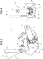
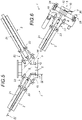
- the extrusion system (1) of the invention as shown in the figures 3 to 6 comprises a thermoplastic material supply device (2) which supplies a distribution block (3) provided for the distribution of molten thermoplastic material (4) through an extrusion die (5) in order to deposit it and superimposing in layers (6, 6', 6") on a support (7) in order to manufacture a three-dimensional object (8).
- the extrusion die (5) as represented according to different variants on the figures 13 to 20 is in particular specific in that it comprises at least one extrusion orifice (9) supplied with thermoplastic material (4) through a passage channel (10) and having a determined contour shape, said extrusion orifice (9) being located laterally in the lower part of the extrusion die (5).
- the extrusion orifice (9) has an exit passage oriented so that the thermoplastic material (4) is expelled along an extrusion axis (11) located in a horizontal plane.
- the laying plane of the extruded thermoplastic material (4) is also horizontal and the thermoplastic material (4) is expelled horizontally, where it would be expelled vertically with a conventional extrusion die.
- the extrusion die (5) as shown schematically in the picture 2 thus differs from conventional and earlier extrusion dies (5a) as shown schematically in the figure 1 , in which the extrusion orifice (9a) is located on the underside of the lower part of the extrusion die, in the vertical extension thereof, and not laterally.
- the passage channel (10) in the distal part located just before the extrusion orifice (9), has an outlet duct (29) which extends perpendicularly to the general axis of the extrusion system (1) of the invention.
- the outlet duct (29) extends along a horizontal axis.
- this outlet duct (29) is no longer horizontal but is inclined with the whole of the extrusion die (5).
- the passage channel (10) forms an angle ⁇ strictly less than 90° with respect to the extrusion axis (11), preferably less than 60° with respect to the axis of extrusion (11) and more preferably less than 30° relative to the extrusion axis (11).
- the extrusion die (5) can have several passage channels (10) in the case where it is provided for extruding several thermoplastic materials (4, 4') simultaneously or not.
- the extrusion die (5) can be provided to carry out mono-extrusion (extrusion of a single thermoplastic material), co-extrusion (simultaneous extrusion of several thermoplastic materials) or multi-extrusion (successive extrusion of several thermoplastic materials).
- the extrusion system (1) of the invention comprises a feed device (2) for thermoplastic material which feeds a distribution block (3) connected to an extrusion die ( 5).
- the extrusion system (1) of the invention comprises several supply devices (2) of thermoplastic material which each supply the same distribution block (3) connected to the same die. extrusion (5).
- the extrusion system (1) of the invention comprises several supply devices (2) of thermoplastic material which each supply the same distribution block (3) connected to one or more dies of extrusion (5).
- the extrusion system (1) of the invention shown in the figures 3 to 6 is a multi-extrusion extrusion system (1), that is to say an extrusion system (1) which makes it possible to deposit several distinct thermoplastic materials simultaneously or alternately.
- the extrusion orifice (9) has an extrusion surface which can be arbitrary, which extends in a plane preferably presenting an angle comprised between 45° and 90°, and more preferentially an angle comprised between 80° and 90°. ° relative to the laying plane of the extruded thermoplastic material (4). He can however have another orientation, in the case for example where the extrusion orifice (9) is bevelled (not shown).
- the extrusion die (5) is also specific in that the extrusion orifice (9) has a width greater than its height, preferably with a width greater than one and a half times its height, and more preferably with a width more than twice its height.
- thermoplastic material (4) in the form of a strip, the width of which depends on the dimensions of the extrusion orifice (9).
- the formation of superimposed layers (6, 6', 6") of thermoplastic material (4) in the form of strips makes it possible to manufacture three-dimensional objects (8) much more quickly than with previous systems where only a thread of material is deposited at each passage of the die.
- the extrusion orifice (9) preferably has an outline of substantially rectangular general shape.
- thermoplastic material(s) (4, 4') are shown.
- the layers (6, 6', 6") have a rectangular cross-section. They are for example layers (6, 6', 6") produced by an extrusion die (5) according to the invention represented on the figures 13 and 14 .
- the extrusion die (5) represented on the figures 13 and 14 comprises a supply chamber (12) of thermoplastic material (4) intended to be supplied with molten thermoplastic material (4) by the distribution block (3) on which it is mounted, said supply chamber (12) supplying in turn the passage channel (10) made of thermoplastic material (4).
- the layers (6, 6', 6") have a rectangular cross-section with an undercut shape on their upper face.
- the extrusion die (5) shown in the figures 18 to 20 has an extrusion orifice (9) the shape of which comprises at least one recessed or raised shape (13) in its part opposite to the plane for depositing the extruded thermoplastic material (4), that is to say say in its upper part as shown in the figures.
- the molten thermoplastic material deposited on a layer (6') has an undercut shape (13') on its upper face while its lower face matches the shapes of the recessed or raised shape (13) of the previous lower layer (6). After stiffening of the thermoplastic material (4), this undercut shape (13') makes it possible to reinforce the cohesion of the different layers (6, 6', 6").
- It is preferably a shape in relief (13), for example dovetail as shown on the figure 10 .
- the layers (6, 6', 6") have a rectangular cross-section with a continuous reinforcement (14), for example of the fiberglass, carbon fiber, metallic thread, textile thread or any other known type
- a continuous reinforcement for example of the fiberglass, carbon fiber, metallic thread, textile thread or any other known type
- the extrusion die (5) shown in the figures 18 to 20 has an additional passage channel (10') into which at least one continuous reinforcement (14) is introduced and which communicates with the extrusion orifice (9) so that said continuous reinforcement (14) is deposited simultaneously with the material thermoplastic (4) extruded.
- the layers (6, 6', 6") have a rectangular section with a single continuous reinforcement (14), several long reinforcements (14) can be introduced simultaneously with the extruded thermoplastic material (4).
- This continuous reinforcement (14) is preferably coated with the thermoplastic material (4) extruded during its removal.
- the continuous reinforcement (14) makes it possible in particular to mechanically reinforce the three-dimensional object (8) produced, but it also makes it possible, for example, to embed electric wires or optical fibers therein.
- the layers (6, 6', 6") have a rectangular cross section and are formed of a core made of a first thermoplastic material (4) and enveloped by a skin made of a second thermoplastic material (4' ).
- These are for example layers (6, 6', 6") produced by an extrusion die (5) according to the invention shown in the figures 15 to 17 .
- the extrusion die (5) represented on the figures 15 to 17 comprises a first passage channel (10) for a first thermoplastic material (4) and a second passage channel (10") for a second thermoplastic material (4'), for example different from the first thermoplastic material (4), said passage channels both opening out at the same extrusion orifice (9).
- the first passage channel (10) is provided substantially at the center of the second channel passage (10") so that the deposited extruded thermoplastic material (4) is formed of a core made up of the first thermoplastic material (4) and enveloped by a skin made up of the second material thermoplastic (4').
- the extrusion die (5) represented on the figures 15 to 17 comprises a first supply chamber (12) provided for the first thermoplastic material (4) and a second supply chamber (12') provided for the second thermoplastic material (4').
- This co-extrusion extrusion die (5) can of course be adapted for the co-extrusion of more than two thermoplastic materials (4, 4').
- the layers (6, 6', 6") have a section of rectangular shape, because this shape is preferred, but the extrusion die (5) according to the invention can of course be adapted to form layers (6, 6', 6") have a section of any shape.
- the distribution block (3) may comprise at least one rotary spindle (16) on which is fixed at least one extrusion die (5) so as to rotate with the latter in a plane parallel to the face for depositing the extruded thermoplastic material (4).
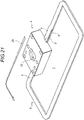
- the rotation of the extrusion die (5) makes it possible to follow any path, without having to interrupt the deposit. of thermoplastic material (4) or to form extra thicknesses due to beads.
- Such a plot is given as an example on the figure 21 , where the direction of movement of the die (5) is indicated by an arrow (28).
- the transition between the layers (6, 6') is deliberately shown marked for reasons of clarity. In reality, this transition can be much more discreet, even undetectable.
- the rotary spindle (16) is a substantially cylindrical part (17) rotatably housed in a cylindrical recess (18) provided in the body of the distribution block (3).
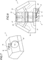
- the distribution block (3) represented on the figures 7 and 8 is provided for carrying out a co-extrusion of two thermoplastic materials (4, 4').
- thermoplastic material (4) for a thermoplastic material (4)
- second passage channel (19') for a second thermoplastic material (4') for a second thermoplastic material (4')
- each passage channel (19, 19 ') being supplied with thermoplastic material (4, 4') by a supply device (2) which is dedicated to him.
- the rotary spindle (16) comprises at least one annular groove (20) open towards the internal face of the cylindrical recess (18) of the body of the distribution block (3), this annular groove (20) communicating both with the passage channels (10, 10") of the extrusion die (5) and with at least one passage channel (19, 19') provided in the body of the distribution block (3), for example via at least one central passage channel (27).
- the two passage channels (19, 19') of the block communicate with the annular groove (20) to supply the same passage channel (10) of the extrusion die (5).
- annular grooves (20) which each communicate with a different passage channel (19, 19') provided in the body of the distribution block (3) to feed passage channels (10, 10") separate from the extrusion die (5).
- the extrusion system (1) comprises actuating members (not shown) for moving the distribution block (3) in translation along three orthogonal axes or following a vector displacement and for moving the rotary spindle (16) in rotation in a plane parallel to the laying plane of the thermoplastic material (4) extruded.
- the actuating members can for example comprise an automated system of the multi-axis robot or gantry type.
- the extrusion system (1) comprises at least one supply device (2) for thermoplastic material (4), preferably in the form of an extrusion screw (21), mounted on the block distribution (3) via an adapter piece (22) and a centering ring (23).
- thermoplastic material (4) makes it possible to deposit thermoplastic material from a filament or a rod of molten thermoplastic material by means of a conventional supply device for this type of device
- a supply device (2) for thermoplastic material (4) in the form of an extrusion screw (21) makes it possible to use a thermoplastic material (4) in the form of granules which are melted in an extruder screw extrusion, and allows in particular the transformation of several materials thermoplastics (4) simultaneously.
- the extrusion system (1) may include a preheating device (24) which heats the laying plane of the thermoplastic material (4) previously extruded upstream of the extrusion die (5) before the laying of a new layer of thermoplastic material (4) or any other heating system making it possible to superficially heat the surface of the previous layer.
- the preheating device (24) comprises a heating resistor which heats the air to a determined temperature before continuously pulsating it under pressure outwards at the level of the laying plane of the thermoplastic material ( 4) previously extruded (previously deposited layer) before depositing the molten material to form the next layer.
- the extrusion system (1) may also comprise a support device (25) which exerts pressure on the layer of molten thermoplastic material (4) which is deposited.
- This support device (25) may for example comprise a pressure cylinder (26) mounted on a spring, driven by a pressurized cylinder, slaved in displacement by a screw system or associated with any other system making it possible to exert a force.
- the support device (25) is located downstream of the extrusion die (5). This support device (25) exerts pressure on the layer (6') of molten thermoplastic material (4) which has just been deposited, in order to improve the contact between the two successive layers and to make it adhere better. to the previous layer (6).
- the extrusion die (5) can be provided to pivot in a vertical plane according to an angle of inclination +/-a with respect to the support (7).
- This angle ⁇ is such that 0° ⁇ 90°, preferentially such that 0° ⁇ 70°, and more preferentially such that 0° ⁇ 50°.
- An extrusion die (5) can be provided to pivot independently of the extrusion system (1) according to the invention, or be provided to pivot together with said system.
- a pivoting extrusion system (1) is shown in the figure 22 , where it is inclined at an angle of inclination of approximately 10°.
- thermoplastic material either in a plane parallel to the deposit plane, or in a plane perpendicular to the laying plane.
Landscapes
- Chemical & Material Sciences (AREA)
- Engineering & Computer Science (AREA)
- Materials Engineering (AREA)
- Physics & Mathematics (AREA)
- Manufacturing & Machinery (AREA)
- Mechanical Engineering (AREA)
- Optics & Photonics (AREA)
- Extrusion Moulding Of Plastics Or The Like (AREA)
Claims (13)
- Verteilerblock (3), vorgesehen zur Verteilung einer Schmelze aus thermoplastischem Material (4) zum Auftragen und Überlagern in Schichten (6, 6', 6") auf einem Träger (7), zum Zweck der Herstellung eines dreidimensionalen Objektes (8)- der Verteilerblock (3) enthält mindestens eine Extrusionsdüse (5) und eine Drehspindel (16) auf der die Extrusionsdüse (5) so befestigt ist, dass sie sich zusammen mit der Spindel in einer Ebene parallel zur Auftragsfläche des extrudierten thermoplastischen Materials (4) dreht;- die Extrusionsdüse (5) ist vorgesehen zum Auftragen und Überlagern von Schichten (6, 6', 6") einer Schmelze aus thermoplastischem Material (4) auf einem Träger (7) entsprechend einer Auftragsebene, zwecks Herstellung eines dreidimensionalen Objektes (8), dabei enthält diese Extrusionsdüse (5) mindestens einen Durchführkanal (10) zur Versorgung mindestens einer Extrusionsöffnung (9) mit thermoplastischem Material (4), durch den das thermoplastische Material (4) aus der Extrusionsdüse (5) ausgestoßen wird, in einer Richtung, die die Extrusionsachse der Extrusionsdüse (5) definiert, die Extrusionsöffnung (9) ist dabei seitlich angeordnet, im unteren Teil der Extrusionsdüse (5), so dass, wenn die Extrusionsdüse (5) eine Neigung von Null bezogen auf eine vertikale Ebene aufweist, das thermoplastische Material (4) aus dieser Extrusionsöffnung (9) ausgestoßen wird, entsprechend einer im Wesentlichen horizontalen Extrusionsachse (11); und. der Extrusionsblock ist dadurch gekennzeichnet, dass es sich bei:- der Drehspindel (16) um ein Teil mit einer im Wesentlichen zylindrischen (17) Form handelt, drehbar angeordnet in einer zylindrischen Aussparung (18), die im Körper des Verteilerblocks (3) vorgesehen ist und die Drehspindel (16) mindestens eine ringförmige Kehle (20) enthält, offen zur Innenseite der zylindrischen Aussparung (18) des Körpers des Verteilerblocks (3), diese ringförmige Kehle (20) steht sowohl mit den Durchführkanälen der Extrusionsdüse (5) wie mit mindestens einem Durchführkanal (10) in Verbindung, der im Körper des Verteilerblocks (3) vorgesehen ist und mit einer Zufuhrvorrichtung (2) für thermoplastisches Material (4) verbunden ist.
- Verteilerblock (3) nach Anspruch 1, dadurch gekennzeichnet, dass der Durchführkanal (10), mindestens in seinem distalen Teil, einen Winkel β von deutlich unter 90° bezogen auf die Extrusionsachse (11) aufweist, noch besser von weniger als 60° bezogen auf die Extrusionsachse (11) und am besten von weniger als 30° bezogen auf die Extrusionsachse (11).
- Verteilerblock (3) nach Anspruch 1 oder 2, dadurch gekennzeichnet, dass die Extrusionsöffnung (9) über eine Extrusionsfläche verfügt, die in einer Ebene verläuft, die einen Winkel von vorzugsweise zwischen 45° und 90° aufweist und noch besser zwischen 80° und 90°, bezogen auf die Auftragsebene des extrudierten thermoplastischen Materials (4).
- Verteilerblock (3) nach irgendeinem der vorangehenden Ansprüche, dadurch gekennzeichnet, dass die Extrusionsöffnung (9) eine Breite hat, die größer ist als ihre Höhe, noch besser eine Breite, die größer ist als das Eineinhalbfache der Höhe und noch besser, eine Breite von mehr als dem Doppelten der Höhe.
- Verteilerblock (3) nach irgendeinem der vorangehenden Ansprüche, dadurch gekennzeichnet, dass die Extrusionsöffnung (9) eine im Wesentlichen rechteckige Kontur hat.
- Verteilerblock (3) nach irgendeinem der vorangehenden Ansprüche, dadurch gekennzeichnet, dass die Kontur der Form der Extrusionsöffnung (9) mindestens eine konkave oder konvexe (13) Form in dem Teil, der der Auftragsebene des extrudierten Materials gegenüberliegt, enthält.
- Verteilerblock (3) nach irgendeinem der vorangehenden Ansprüche, dadurch gekennzeichnet, dass die Extrusionsdüse (5) außerdem mindestens einen zusätzlichen Durchführkanal (10') enthält, um mindestens eine kontinuierliche Verstärkung (14) zuzuführen und der mit der Extrusionsöffnung (9) in Verbindung steht, so dass diese kontinuierliche Verstärkung (14) gleichzeitig mit dem extrudieren thermoplastischen Material (4) aufgetragen wird.
- Verteilerblock (3) nach dem vorangehenden Anspruch, dadurch gekennzeichnet, dass die kontinuierliche Verstärkung (14) vom thermoplastischen Material (4), das bei ihrem Auftrag extrudiert wurde, umhüllt wird.
- Verteilerblock (3) nach irgendeinem der vorangehenden Ansprüche, dadurch gekennzeichnet, dass die Extrusionsdüse (5) einen ersten Durchführkanal (10) für ein erstes thermoplastisches Material (4) enthält und einen zweiten Durchführkanal (10") für ein zweites thermoplastisches Material (4'), das sich vom ersten thermoplastischen Material (4) unterscheidet, diese Durchführkanäle münden beide in Höhe derselben Extrusionsöffnung (9), der erste Durchführkanal (10) ist im Wesentlichen im Zentrum des zweiten Durchführkanals (10") vorgesehen, so dass das extrudierte, aufgetragene thermoplastische Material (4) aus einem Kern besteht, der vom ersten thermoplastischen Material (4) gebildet wird und von einer Haut umgeben ist, die aus dem zweiten thermoplastischen Material (4') besteht.
- Extrusionssystem (1) mit einem Verteilerblock (3) nach irgendeinem der vorangehenden Ansprüche, dadurch gekennzeichnet, dass es mindestens eine Zufuhrvorrichtung (2) für thermoplastisches Material (4) sowie Antriebselemente enthält, um den Verteilerblock (3) nach drei orthogonalen Achsen zu verschieben oder entsprechend einer vektoriellen Verschiebung und um die Drehspindel (16) in Drehung zu versetzen in einer Ebene parallel zur Auftragsebene des extrudierten thermoplastischen Materials (4).
- Extrusionssystem (1) nach Anspruch 10, dadurch gekennzeichnet, dass es außerdem eine Vorwärmvorrichtung (24) enthält, zur Erwärmung der Auftragsebene des zuvor extrudierten thermoplastischen Materials (4) vor der Extrusionsdüse (5) vor dem Auftragen einer neuen Schicht thermoplastischen Materials (4) oder eine Heizvorrichtung zur oberflächlichen Erwärmung der Oberfläche der zuvor extrudierten thermoplastischen Materialschicht (4).
- Extrusionssystem (1) nach Anspruch 10 oder 11, dadurch gekennzeichnet, dass es außerdem eine Stützvorrichtung (25) hinter der Extrusionsdüse (5) enthält, um einen Druck auf die geschmolzene Schicht thermoplastischen Materials (4) auszuüben, die darauf aufgetragen wird.
- Extrusionssystem (1) nach einem beliebigen der Ansprüche 10 bis 12, dadurch gekennzeichnet, dass mindestens eine Extrusionsdüse (5) in vertikaler Ebene schwenkbar vorgesehen ist, entsprechend einem Neigungswinkel von +/-α, bezogen auf den Träger (7), dieser Winkel α ist 0°<α<90°, besser noch 0°<α<70°, und noch besser 0°<α<50°.
Applications Claiming Priority (2)
| Application Number | Priority Date | Filing Date | Title |
|---|---|---|---|
| FR1850404A FR3076761B1 (fr) | 2018-01-18 | 2018-01-18 | Outil ameliore de depot en 3 dimensions de matiere par extrusion |
| PCT/FR2019/050094 WO2019141946A1 (fr) | 2018-01-18 | 2019-01-17 | Outil ameliore de depot en 3 dimensions de matiere par extrusion |
Publications (2)
| Publication Number | Publication Date |
|---|---|
| EP3740372A1 EP3740372A1 (de) | 2020-11-25 |
| EP3740372B1 true EP3740372B1 (de) | 2023-01-04 |
Family
ID=61913381
Family Applications (1)
| Application Number | Title | Priority Date | Filing Date |
|---|---|---|---|
| EP19706729.1A Active EP3740372B1 (de) | 2018-01-18 | 2019-01-17 | Werkzeug zum dreidimensionalen auftragen von material durch extrusion |
Country Status (3)
| Country | Link |
|---|---|
| EP (1) | EP3740372B1 (de) |
| FR (1) | FR3076761B1 (de) |
| WO (1) | WO2019141946A1 (de) |
Cited By (1)
| Publication number | Priority date | Publication date | Assignee | Title |
|---|---|---|---|---|
| EP4132768B1 (de) * | 2020-04-08 | 2024-11-13 | Liqtra GmbH | Druckvorrichtung, vorzugsweise 3d-drucker |
Families Citing this family (1)
| Publication number | Priority date | Publication date | Assignee | Title |
|---|---|---|---|---|
| DE102023002038A1 (de) * | 2023-05-19 | 2024-11-21 | Technische Universität Dortmund, Körperschaft des öffentlichen Rechts | Druckeinrichtung für den 3D-Druck |
Family Cites Families (7)
| Publication number | Priority date | Publication date | Assignee | Title |
|---|---|---|---|---|
| DE202005012524U1 (de) * | 2005-08-05 | 2005-10-20 | Diamant-Metallplastic Gmbh | Vorrichtung zum Formen dreidimensionaler Gebilde aus einem spritzfähigen Material |
| US20150174824A1 (en) * | 2013-12-19 | 2015-06-25 | Karl Joseph Gifford | Systems and methods for 3D printing with multiple exchangeable printheads |
| US9796140B2 (en) * | 2014-06-19 | 2017-10-24 | Autodesk, Inc. | Automated systems for composite part fabrication |
| EP3359371B1 (de) * | 2015-10-09 | 2023-05-03 | Largix Tech Ltd. | Generative fertigung unter verwendung von polymermaterialien |
| CN109070200A (zh) * | 2016-03-03 | 2018-12-21 | 德仕托金属有限公司 | 使用金属构建材料的增材制造 |
| CN106985380B (zh) * | 2017-06-05 | 2018-03-30 | 六安永贞匠道机电科技有限公司 | 3d打印机的水平无支撑打印的多喷头系统 |
| CN107521103B (zh) * | 2017-09-06 | 2019-08-23 | 严红飞 | 3d打印机的形态切换机构 |
-
2018
- 2018-01-18 FR FR1850404A patent/FR3076761B1/fr not_active Expired - Fee Related
-
2019
- 2019-01-17 WO PCT/FR2019/050094 patent/WO2019141946A1/fr not_active Ceased
- 2019-01-17 EP EP19706729.1A patent/EP3740372B1/de active Active
Cited By (1)
| Publication number | Priority date | Publication date | Assignee | Title |
|---|---|---|---|---|
| EP4132768B1 (de) * | 2020-04-08 | 2024-11-13 | Liqtra GmbH | Druckvorrichtung, vorzugsweise 3d-drucker |
Also Published As
| Publication number | Publication date |
|---|---|
| FR3076761A1 (fr) | 2019-07-19 |
| FR3076761B1 (fr) | 2020-07-24 |
| EP3740372A1 (de) | 2020-11-25 |
| WO2019141946A1 (fr) | 2019-07-25 |
Similar Documents
| Publication | Publication Date | Title |
|---|---|---|
| EP3448194B1 (de) | Verbesserte befestigungsvorrichtung mit verstärkten befestigungselementen | |
| EP2651630B1 (de) | Verfahren und vorrichtung zur herstellung eines reifens unter verwendung einer lage aus zwei kautschukzusammensetzungen | |
| EP3740372B1 (de) | Werkzeug zum dreidimensionalen auftragen von material durch extrusion | |
| FR2784657A1 (fr) | Tube a tete en materiaux multicouches et procede de fabrication | |
| EP0179521B1 (de) | Einstellbarer Beschickungsblock für eine Koextrudierdüse | |
| FR2886203A1 (fr) | Filiere pour la realisation de structures planes de grande largeur a base de matiere plastique | |
| EP1893398B1 (de) | Verfahren zur herstellung einer verstärkung für einen verbundwerkstoff mit variablem beständigkeitsprofil und auf diese weise hergestellte verstärkung | |
| FR2793460A1 (fr) | Composant decoratif et procede de fabrication d'un tel composant decoratif et procede de fabrication d'une piece d'habillage interieur d'un vehicule, par exemple, un panneau de portiere, utilisant ledit composant decoratif | |
| FR2650217A1 (fr) | Procede et dispositif de revetement de protection thermique interne de propulseur | |
| EP1565303B1 (de) | Verfahren zur herstellung von flexiblen röhren aus kunststoff oder aus metallplastischem material | |
| WO2008141871A1 (fr) | Buse articulee et procede d ' application d ' une bandelette en materiau viscoelastique qui utilise ladite buse | |
| EP0419338B1 (de) | Thermische Schutzschicht, Verfahren und Herstellungsanlage | |
| FR2544657A1 (fr) | Procede et dispositif pour fabriquer des corps creux comportant une paroi formee, par endroits, de deux ou plusieurs couches | |
| FR3050620B1 (fr) | Dispositif de retenue ameliore comprenant des elements de retenue renforces | |
| EP4371734A1 (de) | Verstärkte filamentextrusionswerkzeug zur generativen fertigung | |
| FR2989304A1 (fr) | Procede et systeme de realisation d'un element de garnissage comprenant une couche de revetement preformee | |
| FR3050624B1 (fr) | Appareillage et procede ameliores pour la formation d'elements de retenue par formage | |
| FR3050623B1 (fr) | Procede et appareillage ameliores pour la formation d'elements de retenue | |
| FR3050621B1 (fr) | Dispositif de retenue ameliore a crochets presentant des bords ameliores | |
| WO2025224258A1 (fr) | Procédé de fabrication d'un élément composite 3d | |
| EP1282502B1 (de) | Extrusionskopfschmelzeverteiler und gebrauch des verteilers in einem extrusionskopf | |
| WO2022248315A1 (fr) | Appareil de chauffage pour réaliser une activation thermique localisée d'une pièce composite | |
| FR3050622B1 (fr) | Appareillage et procede pour la solidarisation d'un substrat a un ruban plastique | |
| FR3157254A1 (fr) | Procédé de fabrication additive par ajout de couches thermoplastiques activées par plasma | |
| CH716752B1 (fr) | Moule à fromage, en particulier pour fromage du type comté, et procédé de fabrication d'un tel moule. |
Legal Events
| Date | Code | Title | Description |
|---|---|---|---|
| STAA | Information on the status of an ep patent application or granted ep patent |
Free format text: STATUS: UNKNOWN |
|
| STAA | Information on the status of an ep patent application or granted ep patent |
Free format text: STATUS: THE INTERNATIONAL PUBLICATION HAS BEEN MADE |
|
| PUAI | Public reference made under article 153(3) epc to a published international application that has entered the european phase |
Free format text: ORIGINAL CODE: 0009012 |
|
| STAA | Information on the status of an ep patent application or granted ep patent |
Free format text: STATUS: REQUEST FOR EXAMINATION WAS MADE |
|
| 17P | Request for examination filed |
Effective date: 20200710 |
|
| AK | Designated contracting states |
Kind code of ref document: A1 Designated state(s): AL AT BE BG CH CY CZ DE DK EE ES FI FR GB GR HR HU IE IS IT LI LT LU LV MC MK MT NL NO PL PT RO RS SE SI SK SM TR |
|
| AX | Request for extension of the european patent |
Extension state: BA ME |
|
| DAV | Request for validation of the european patent (deleted) | ||
| DAX | Request for extension of the european patent (deleted) | ||
| GRAP | Despatch of communication of intention to grant a patent |
Free format text: ORIGINAL CODE: EPIDOSNIGR1 |
|
| STAA | Information on the status of an ep patent application or granted ep patent |
Free format text: STATUS: GRANT OF PATENT IS INTENDED |
|
| RIC1 | Information provided on ipc code assigned before grant |
Ipc: B33Y 30/00 20150101ALI20220701BHEP Ipc: B29C 64/209 20170101ALI20220701BHEP Ipc: B29C 64/336 20170101ALI20220701BHEP Ipc: B29C 64/106 20170101AFI20220701BHEP |
|
| INTG | Intention to grant announced |
Effective date: 20220726 |
|
| GRAS | Grant fee paid |
Free format text: ORIGINAL CODE: EPIDOSNIGR3 |
|
| GRAA | (expected) grant |
Free format text: ORIGINAL CODE: 0009210 |
|
| STAA | Information on the status of an ep patent application or granted ep patent |
Free format text: STATUS: THE PATENT HAS BEEN GRANTED |
|
| AK | Designated contracting states |
Kind code of ref document: B1 Designated state(s): AL AT BE BG CH CY CZ DE DK EE ES FI FR GB GR HR HU IE IS IT LI LT LU LV MC MK MT NL NO PL PT RO RS SE SI SK SM TR |
|
| REG | Reference to a national code |
Ref country code: GB Ref legal event code: FG4D Free format text: NOT ENGLISH |
|
| REG | Reference to a national code |
Ref country code: DE Ref legal event code: R096 Ref document number: 602019023945 Country of ref document: DE |
|
| REG | Reference to a national code |
Ref country code: CH Ref legal event code: EP |
|
| REG | Reference to a national code |
Ref country code: AT Ref legal event code: REF Ref document number: 1541623 Country of ref document: AT Kind code of ref document: T Effective date: 20230115 |
|
| REG | Reference to a national code |
Ref country code: IE Ref legal event code: FG4D Free format text: LANGUAGE OF EP DOCUMENT: FRENCH |
|
| REG | Reference to a national code |
Ref country code: LT Ref legal event code: MG9D |
|
| REG | Reference to a national code |
Ref country code: NL Ref legal event code: MP Effective date: 20230104 |
|
| REG | Reference to a national code |
Ref country code: AT Ref legal event code: MK05 Ref document number: 1541623 Country of ref document: AT Kind code of ref document: T Effective date: 20230104 |
|
| PG25 | Lapsed in a contracting state [announced via postgrant information from national office to epo] |
Ref country code: NL Free format text: LAPSE BECAUSE OF FAILURE TO SUBMIT A TRANSLATION OF THE DESCRIPTION OR TO PAY THE FEE WITHIN THE PRESCRIBED TIME-LIMIT Effective date: 20230104 |
|
| PG25 | Lapsed in a contracting state [announced via postgrant information from national office to epo] |
Ref country code: RS Free format text: LAPSE BECAUSE OF FAILURE TO SUBMIT A TRANSLATION OF THE DESCRIPTION OR TO PAY THE FEE WITHIN THE PRESCRIBED TIME-LIMIT Effective date: 20230104 Ref country code: PT Free format text: LAPSE BECAUSE OF FAILURE TO SUBMIT A TRANSLATION OF THE DESCRIPTION OR TO PAY THE FEE WITHIN THE PRESCRIBED TIME-LIMIT Effective date: 20230504 Ref country code: NO Free format text: LAPSE BECAUSE OF FAILURE TO SUBMIT A TRANSLATION OF THE DESCRIPTION OR TO PAY THE FEE WITHIN THE PRESCRIBED TIME-LIMIT Effective date: 20230404 Ref country code: LV Free format text: LAPSE BECAUSE OF FAILURE TO SUBMIT A TRANSLATION OF THE DESCRIPTION OR TO PAY THE FEE WITHIN THE PRESCRIBED TIME-LIMIT Effective date: 20230104 Ref country code: LT Free format text: LAPSE BECAUSE OF FAILURE TO SUBMIT A TRANSLATION OF THE DESCRIPTION OR TO PAY THE FEE WITHIN THE PRESCRIBED TIME-LIMIT Effective date: 20230104 Ref country code: HR Free format text: LAPSE BECAUSE OF FAILURE TO SUBMIT A TRANSLATION OF THE DESCRIPTION OR TO PAY THE FEE WITHIN THE PRESCRIBED TIME-LIMIT Effective date: 20230104 Ref country code: ES Free format text: LAPSE BECAUSE OF FAILURE TO SUBMIT A TRANSLATION OF THE DESCRIPTION OR TO PAY THE FEE WITHIN THE PRESCRIBED TIME-LIMIT Effective date: 20230104 Ref country code: AT Free format text: LAPSE BECAUSE OF FAILURE TO SUBMIT A TRANSLATION OF THE DESCRIPTION OR TO PAY THE FEE WITHIN THE PRESCRIBED TIME-LIMIT Effective date: 20230104 |
|
| PG25 | Lapsed in a contracting state [announced via postgrant information from national office to epo] |
Ref country code: SE Free format text: LAPSE BECAUSE OF FAILURE TO SUBMIT A TRANSLATION OF THE DESCRIPTION OR TO PAY THE FEE WITHIN THE PRESCRIBED TIME-LIMIT Effective date: 20230104 Ref country code: PL Free format text: LAPSE BECAUSE OF FAILURE TO SUBMIT A TRANSLATION OF THE DESCRIPTION OR TO PAY THE FEE WITHIN THE PRESCRIBED TIME-LIMIT Effective date: 20230104 Ref country code: IS Free format text: LAPSE BECAUSE OF FAILURE TO SUBMIT A TRANSLATION OF THE DESCRIPTION OR TO PAY THE FEE WITHIN THE PRESCRIBED TIME-LIMIT Effective date: 20230504 Ref country code: GR Free format text: LAPSE BECAUSE OF FAILURE TO SUBMIT A TRANSLATION OF THE DESCRIPTION OR TO PAY THE FEE WITHIN THE PRESCRIBED TIME-LIMIT Effective date: 20230405 Ref country code: FI Free format text: LAPSE BECAUSE OF FAILURE TO SUBMIT A TRANSLATION OF THE DESCRIPTION OR TO PAY THE FEE WITHIN THE PRESCRIBED TIME-LIMIT Effective date: 20230104 |
|
| REG | Reference to a national code |
Ref country code: CH Ref legal event code: PL |
|
| PG25 | Lapsed in a contracting state [announced via postgrant information from national office to epo] |
Ref country code: LU Free format text: LAPSE BECAUSE OF NON-PAYMENT OF DUE FEES Effective date: 20230117 |
|
| REG | Reference to a national code |
Ref country code: BE Ref legal event code: MM Effective date: 20230131 |
|
| REG | Reference to a national code |
Ref country code: DE Ref legal event code: R097 Ref document number: 602019023945 Country of ref document: DE |
|
| PG25 | Lapsed in a contracting state [announced via postgrant information from national office to epo] |
Ref country code: SM Free format text: LAPSE BECAUSE OF FAILURE TO SUBMIT A TRANSLATION OF THE DESCRIPTION OR TO PAY THE FEE WITHIN THE PRESCRIBED TIME-LIMIT Effective date: 20230104 Ref country code: RO Free format text: LAPSE BECAUSE OF FAILURE TO SUBMIT A TRANSLATION OF THE DESCRIPTION OR TO PAY THE FEE WITHIN THE PRESCRIBED TIME-LIMIT Effective date: 20230104 Ref country code: MC Free format text: LAPSE BECAUSE OF FAILURE TO SUBMIT A TRANSLATION OF THE DESCRIPTION OR TO PAY THE FEE WITHIN THE PRESCRIBED TIME-LIMIT Effective date: 20230104 Ref country code: LI Free format text: LAPSE BECAUSE OF NON-PAYMENT OF DUE FEES Effective date: 20230131 Ref country code: EE Free format text: LAPSE BECAUSE OF FAILURE TO SUBMIT A TRANSLATION OF THE DESCRIPTION OR TO PAY THE FEE WITHIN THE PRESCRIBED TIME-LIMIT Effective date: 20230104 Ref country code: DK Free format text: LAPSE BECAUSE OF FAILURE TO SUBMIT A TRANSLATION OF THE DESCRIPTION OR TO PAY THE FEE WITHIN THE PRESCRIBED TIME-LIMIT Effective date: 20230104 Ref country code: CZ Free format text: LAPSE BECAUSE OF FAILURE TO SUBMIT A TRANSLATION OF THE DESCRIPTION OR TO PAY THE FEE WITHIN THE PRESCRIBED TIME-LIMIT Effective date: 20230104 Ref country code: CH Free format text: LAPSE BECAUSE OF NON-PAYMENT OF DUE FEES Effective date: 20230131 |
|
| PLBE | No opposition filed within time limit |
Free format text: ORIGINAL CODE: 0009261 |
|
| STAA | Information on the status of an ep patent application or granted ep patent |
Free format text: STATUS: NO OPPOSITION FILED WITHIN TIME LIMIT |
|
| PG25 | Lapsed in a contracting state [announced via postgrant information from national office to epo] |
Ref country code: SK Free format text: LAPSE BECAUSE OF FAILURE TO SUBMIT A TRANSLATION OF THE DESCRIPTION OR TO PAY THE FEE WITHIN THE PRESCRIBED TIME-LIMIT Effective date: 20230104 Ref country code: BE Free format text: LAPSE BECAUSE OF NON-PAYMENT OF DUE FEES Effective date: 20230131 |
|
| 26N | No opposition filed |
Effective date: 20231005 |
|
| GBPC | Gb: european patent ceased through non-payment of renewal fee |
Effective date: 20230404 |
|
| PG25 | Lapsed in a contracting state [announced via postgrant information from national office to epo] |
Ref country code: GB Free format text: LAPSE BECAUSE OF NON-PAYMENT OF DUE FEES Effective date: 20230404 |
|
| PG25 | Lapsed in a contracting state [announced via postgrant information from national office to epo] |
Ref country code: SI Free format text: LAPSE BECAUSE OF FAILURE TO SUBMIT A TRANSLATION OF THE DESCRIPTION OR TO PAY THE FEE WITHIN THE PRESCRIBED TIME-LIMIT Effective date: 20230104 Ref country code: IE Free format text: LAPSE BECAUSE OF NON-PAYMENT OF DUE FEES Effective date: 20230117 Ref country code: GB Free format text: LAPSE BECAUSE OF NON-PAYMENT OF DUE FEES Effective date: 20230404 |
|
| PGFP | Annual fee paid to national office [announced via postgrant information from national office to epo] |
Ref country code: DE Payment date: 20240117 Year of fee payment: 6 |
|
| PG25 | Lapsed in a contracting state [announced via postgrant information from national office to epo] |
Ref country code: IT Free format text: LAPSE BECAUSE OF FAILURE TO SUBMIT A TRANSLATION OF THE DESCRIPTION OR TO PAY THE FEE WITHIN THE PRESCRIBED TIME-LIMIT Effective date: 20230104 |
|
| PGFP | Annual fee paid to national office [announced via postgrant information from national office to epo] |
Ref country code: FR Payment date: 20240129 Year of fee payment: 6 |
|
| PG25 | Lapsed in a contracting state [announced via postgrant information from national office to epo] |
Ref country code: BG Free format text: LAPSE BECAUSE OF FAILURE TO SUBMIT A TRANSLATION OF THE DESCRIPTION OR TO PAY THE FEE WITHIN THE PRESCRIBED TIME-LIMIT Effective date: 20230104 |
|
| PG25 | Lapsed in a contracting state [announced via postgrant information from national office to epo] |
Ref country code: BG Free format text: LAPSE BECAUSE OF FAILURE TO SUBMIT A TRANSLATION OF THE DESCRIPTION OR TO PAY THE FEE WITHIN THE PRESCRIBED TIME-LIMIT Effective date: 20230104 |
|
| PG25 | Lapsed in a contracting state [announced via postgrant information from national office to epo] |
Ref country code: CY Free format text: LAPSE BECAUSE OF FAILURE TO SUBMIT A TRANSLATION OF THE DESCRIPTION OR TO PAY THE FEE WITHIN THE PRESCRIBED TIME-LIMIT; INVALID AB INITIO Effective date: 20190117 |
|
| REG | Reference to a national code |
Ref country code: DE Ref legal event code: R119 Ref document number: 602019023945 Country of ref document: DE |
|
| PG25 | Lapsed in a contracting state [announced via postgrant information from national office to epo] |
Ref country code: HU Free format text: LAPSE BECAUSE OF FAILURE TO SUBMIT A TRANSLATION OF THE DESCRIPTION OR TO PAY THE FEE WITHIN THE PRESCRIBED TIME-LIMIT; INVALID AB INITIO Effective date: 20190117 |
|
| PG25 | Lapsed in a contracting state [announced via postgrant information from national office to epo] |
Ref country code: DE Free format text: LAPSE BECAUSE OF NON-PAYMENT OF DUE FEES Effective date: 20250801 |
|
| PG25 | Lapsed in a contracting state [announced via postgrant information from national office to epo] |
Ref country code: FR Free format text: LAPSE BECAUSE OF NON-PAYMENT OF DUE FEES Effective date: 20250131 |
|
| PG25 | Lapsed in a contracting state [announced via postgrant information from national office to epo] |
Ref country code: TR Free format text: LAPSE BECAUSE OF FAILURE TO SUBMIT A TRANSLATION OF THE DESCRIPTION OR TO PAY THE FEE WITHIN THE PRESCRIBED TIME-LIMIT Effective date: 20230104 |