EP3740407B1 - Support d'appareils encastrés pour un véhicule sur rails - Google Patents
Support d'appareils encastrés pour un véhicule sur rails Download PDFInfo
- Publication number
- EP3740407B1 EP3740407B1 EP19710351.8A EP19710351A EP3740407B1 EP 3740407 B1 EP3740407 B1 EP 3740407B1 EP 19710351 A EP19710351 A EP 19710351A EP 3740407 B1 EP3740407 B1 EP 3740407B1
- Authority
- EP
- European Patent Office
- Prior art keywords
- air
- underfloor
- guiding device
- rail vehicle
- equipment carrier
- Prior art date
- Legal status (The legal status is an assumption and is not a legal conclusion. Google has not performed a legal analysis and makes no representation as to the accuracy of the status listed.)
- Active
Links
Images

Classifications
-
- B—PERFORMING OPERATIONS; TRANSPORTING
- B61—RAILWAYS
- B61D—BODY DETAILS OR KINDS OF RAILWAY VEHICLES
- B61D27/00—Heating, cooling, ventilating, or air-conditioning
- B61D27/0072—Means for cooling only
-
- B—PERFORMING OPERATIONS; TRANSPORTING
- B61—RAILWAYS
- B61C—LOCOMOTIVES; MOTOR RAILCARS
- B61C17/00—Arrangement or disposition of parts; Details or accessories not otherwise provided for; Use of control gear and control systems
-
- B—PERFORMING OPERATIONS; TRANSPORTING
- B61—RAILWAYS
- B61C—LOCOMOTIVES; MOTOR RAILCARS
- B61C17/00—Arrangement or disposition of parts; Details or accessories not otherwise provided for; Use of control gear and control systems
- B61C17/04—Arrangement or disposition of driving cabins, footplates or engine rooms; Ventilation thereof
-
- B—PERFORMING OPERATIONS; TRANSPORTING
- B61—RAILWAYS
- B61F—RAIL VEHICLE SUSPENSIONS, e.g. UNDERFRAMES, BOGIES OR ARRANGEMENTS OF WHEEL AXLES; RAIL VEHICLES FOR USE ON TRACKS OF DIFFERENT WIDTH; PREVENTING DERAILING OF RAIL VEHICLES; WHEEL GUARDS, OBSTRUCTION REMOVERS OR THE LIKE FOR RAIL VEHICLES
- B61F1/00—Underframes
- B61F1/08—Details
Definitions
- the invention relates to an underfloor device carrier for a rail vehicle.
- Underfloor equipment carriers also known as underfloor containers, are very often used in rail vehicles and are used to accommodate electrical equipment, preferably equipment with a high energy requirement. They offer the advantage of being able to set up and test these electrical devices separately from the car body of the rail vehicle, and they are installed under the car body during final assembly of the vehicle.
- a certain electrical power loss occurs, which is typically dissipated by means of forced air cooling. Ambient air is sucked in at one point of the underfloor device carrier via an air filter, conducted inside the device carrier over heat-dissipating surfaces and released back into the environment at another point. Depending on the device to be cooled, the discharged air can have different temperatures.
- Underfloor devices with braking resistors represent an extreme case, which can reach up to 700 degrees Celsius and cause a very hot exhaust air flow. If this is not a problem even when driving on the open road, this exhaust air can lead to problems in bus stops, especially in tunnels. Exhaust air escaping through the platform gap in the door area represents a loss of comfort for the passengers and can, in extreme cases, lead to injuries.
- the warm exhaust air penetrating into the passenger compartment may also have to be cooled down again by the air conditioning system. Turning off the ventilation of the devices to be cooled while stopped in a station is not an acceptable option, since braking resistors, for example, have the highest cooling requirements at this time.
- the document DE 42 23 647 A1 discloses an underfloor device carrier for a rail vehicle, comprising forced ventilation.
- the document DE 10 2015 202815 A1 discloses a rooftop cooling system with adjustable guide vanes.
- the invention is therefore based on the object of specifying an underfloor device carrier for a rail vehicle which avoids the disadvantages of the prior art and at the same time offers the maximum intended cooling capacity or cooling air flow at any time during operation.
- an underfloor device carrier for a rail vehicle which comprises forced ventilation with at least one supply air intake point and at least one exhaust air outlet opening, with an air guiding device being provided which can be switched between at least two positions, with the exhaust air being released in a first position of the air guiding device flows out in a first outflow direction and in a second position of the air guiding device, the exhaust air flows out in a second outflow direction.
- the advantage can be achieved of being able to discharge the exhaust air in a specific direction, so that it can be steered in that direction which is advantageous at the respective point in time.
- an underfloor device carrier is equipped with an air cooling system, wherein ambient air can be sucked in via at least one air intake point, and the cooling air is blown out either in a first or a second outflow direction.
- an air guiding device is to be provided, which effects the corresponding steering of the air flow.
- This air guiding device can include flaps, for example, which are controlled in such a way that they open or close specific paths for the cooling air.
- the outflow directions are oriented in such a way that they blow out the exhaust air in opposite directions.
- the exhaust air In the installed position of the device carrier, it is thus possible to let the exhaust air flow out transversely to the longitudinal direction of the rail vehicle, with the exhaust air being blown out only in the opposite direction to the platform when it is stopped. In this way, passenger comfort can be prevented from being impaired by hot air escaping from the platform gap, which is particularly important in tunnels.
- the cooling air is typically sucked in either on both sides (related to the longitudinal sides of a rail vehicle) or from below, from the direction of the track bed. In In the first case, the exhaust air is blown out downwards, in the second case to both sides.
- air baffles can be provided, which are pivotably arranged in the air flow and thus allow the air flow to exit in a directed manner.
- outlet opening to be designed in such a way that it has two types of outlet channels, each of which directs the exhaust air in one direction, and to close one type of outlet channel in each case depending on the desired outlet direction.
- the air guiding device is preferably controlled automatically and by means of an electric drive.
- a controller must be provided which receives information from vehicle-mounted devices (e.g. door controller or vehicle controller) about the exhaust side to be selected, which is required at the stop currently being approached.
- vehicle-mounted devices e.g. door controller or vehicle controller
- This controller includes the power electronics required to drive the air guiding device and optionally means for detecting the operating state of the associated drives and for detecting errors in these components. It is particularly advantageous to provide a bidirectional data interface via which commands from on-board devices can be transmitted to the control device and status or error messages can be transmitted to the on-board devices.
- the other embodiment of the invention provides that the air guiding device is directly actuated mechanically by a door drive or a drive for bridging a gap.
- a door or gap bridging drive can also drive the air deflector of an underfloor device carrier at the same time as the door or the gap bridging. It is particularly advantageous to use the drive of a gap bridging, since this acts before opening the door and after closing the door, so that the In any case, the air guiding device is placed in the correct position before the door is opened.
- the drive force can be transmitted to the air guiding device, for example, by means of a Bowden cable.
- variable cooling air blow-out of an underfloor device carrier can also be implemented, but with reduced efficiency and higher production costs.
- separate fans and associated air paths to a respective exhaust air outlet opening can be provided for each blow-out direction, which does not require a variable air guide device, but increases the manufacturing cost.
- cooling air fan is designed to be reversible, so that the supply air intake point and the exhaust air outlet opening can exchange their function as desired.
- this is not advantageous since conventional fans only have a high level of efficiency in one air conveying direction, and this is usually extremely low in the opposite direction. This could only be solved by using expensive fans with blade adjustment.
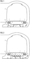
- FIG.1 shows an example and a schematic of an underfloor device carrier with a downward discharge.
- a conventional underfloor device carrier 1 is shown, which is arranged on the underside of a rail vehicle 2 which is located at a station in a tunnel.
- the underfloor device carrier 1 has two laterally arranged supply air intake points 3 through which supply air 7 is sucked into the interior of the underfloor device carrier 1 .
- the subsequently heated exhaust air 6 is blown out on the underside of the underfloor device carrier 1 via an exhaust air outlet opening 4 and is distributed below the rail vehicle 2, with part of the exhaust air 6 flowing into the space between the rail vehicle 2 and the tunnel wall and another part of the exhaust air 6 through the platform gap 8 towards the platform.
- Fig.2 shows an example and schematically an underfloor device carrier according to the invention with a blow-out downwards on a left-hand platform. It is an identical situation as in Fig.1 shown, where however an underfloor device carrier 1 according to the invention is arranged below the rail vehicle 2 . Like the underfloor device carrier according to the prior art, this includes two laterally arranged supply air intake points 3. The exhaust air 6 is discharged via an exhaust air outlet opening 4 on the underside of the underfloor device carrier 1, with an air guiding device 5 being provided, via which the exit direction of the exhaust air 6 can be specified .
- This air guiding device 5 can be implemented in the form of a plurality of air guiding plates, which can each assume at least two positions in relation to the air flow and can thus steer it in certain directions.
- the air baffles of the air guiding device 5 are positioned in such a way that the exhaust air 6 flows in the direction of the tunnel wall, i.e. opposite to the platform, and thus practically no part of the exhaust air 6 passes through the platform gap in the direction of the platform.
- a drive for example an electric motor, a stepper motor or an electromagnet, is provided for moving the air guide plates of the air guide device 5 . Such a drive is not shown to simplify the schematic diagram.
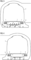
- Fig.3 shows an example and schematically an underfloor device carrier according to the invention with a blow-out downwards on a right-hand platform. It is the embodiment of an underfloor device carrier 1 from Fig.2 shown, with the rail vehicle 2 stopping at a stop with a platform on the right-hand side of the vehicle.
- the air guide plates of the air guide device 5 are positioned in such a way that the exhaust air 6 is blown out on the left-hand side of the vehicle longitudinal axis and thus cannot pass through the platform gap 8 .
- the air baffles of the air guiding device 5 can therefore already be brought into the position required for the next stop while driving or remain in the last position until the next stop.
- the air guide plates of the air guide device 5 can be brought into a neutral central position. This can be particularly advantageous if the lowest flow resistance of the air guiding device 5 occurs in this neutral middle position and the exhaust air 6 thus achieves the greatest possible volume flow while driving.
- FIG.4 shows an example and schematic of an underfloor device carrier with a lateral air outlet.
- a conventional underfloor device carrier 1 is shown, which is arranged on the underside of a rail vehicle 2 which is located at a station in a tunnel.
- the underfloor device carrier 1 has a supply air intake point 3 arranged below, through which supply air 7 is sucked into the interior of the underfloor device carrier 1 .
- the subsequently heated exhaust air 6 is blown out on the sides of the underfloor device carrier 1 via two exhaust air outlet openings 4 .
- a part of the exhaust air 6 flows into the space between the rail vehicle 2 and the tunnel wall, but other part of the exhaust air 6 is blown out directly below the platform gap 8 in the direction of the platform, which is particularly disadvantageous.
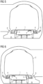
- Fig.5 shows an example and schematically an underfloor device carrier according to the invention with a lateral Blowout on a left-hand platform. It is an identical situation as in Fig.4 shown, but an underfloor device carrier 1 according to the invention is arranged below the rail vehicle 2 . Like the underfloor device carrier according to the prior art, this includes two laterally arranged exhaust air outlet openings 4.
- An air guiding device 5 is provided which includes two flaps, one flap each being assigned to an exhaust air outlet opening 4 and being set up in such a way that they close the respective exhaust air outlet opening 4 can.
- the flaps of the air guiding device 5 can preferably be adjusted independently of one another into an open and a closed position with the aid of a force.
- the outlet direction of the exhaust air 6 can be specified, so that, as in the exemplary embodiment shown, the exhaust air outlet opening 4 on the platform side can be closed and the entire exhaust air 6 exits through the exhaust air outlet opening 4 on the tunnel side.
- a drive for example an electric motor, a stepping motor or an electromagnet, is provided for moving the flaps of the air guiding device 5 . Such a drive is not shown to simplify the schematic diagram.
- Fig.6 shows an example and schematically an underfloor device carrier according to the invention with a lateral blow-out on a right-hand platform. It is the embodiment from Fig.5 shown, wherein during a stop at a platform on the right-hand side, the flaps of the air-guiding device 5 on the right-hand side of the vehicle are closed, so that the exhaust air 6 is blown out at the exhaust-air outlet opening 4 on the tunnel side. It is advisable to close all flaps of the air guiding device 5 while driving open, as this achieves the best cooling effect for the components to be cooled in the underfloor device carrier 1.
- Fig.7 shows, by way of example and schematically, the electrical block diagram of an underfloor device carrier 1 according to the invention.
- the underfloor device carrier 1 comprises a control device 9 which is set up to operate an electric drive 12 .
- This drive 12 acts on an air guiding device 5, so that it is able to place its means for controlling the air flow (flaps or air baffles) in the required position.
- Function monitoring of the air guiding device 5 is provided, in which a position feedback signal 13 is sent from the air guiding device 5 to the control device 9 .
- a malfunction of the drive 12 or of the air guiding device 5 can be detected.
- the control device 9 is connected to a vehicle-side controller 10 by means of a data interface, so that data 11 can be transmitted in both directions between the control device 9 and the vehicle-side controller 10 . Commands can be transmitted to the control device 9 and feedback to the on-board controller 10 via this data interface.
- Fig.8 shows an example and diagrammatically of an underfloor device carrier with a mechanically driven air guiding device.
- a section through an underfloor device carrier 1 is shown, which is arranged on the underside of a rail vehicle 2 .
- the rail vehicle 2 is equipped with a gap bridging in the form of a sliding step 14 which can be actuated by means of a sliding step drive 15 .
- the Underfloor device carrier 1 is after in the Figures 5 and 6 principle shown, according to which alternatively one of two exhaust air outlet openings 4 can be closed.
- the air guiding device 5 is therefore equipped with flaps.
- the sliding step drive 15 acts on the movably mounted step plate and via a power transmission 16 also on the air guiding device 5 and thus moves the flaps.
- This power transmission 16 can be designed, for example, as a Bowden cable, as a hydraulic power transmission, or as a rod drive.
- 8 only one half of the underfloor device carrier 1 is shown, the other half is a mirror image of the first half.
- the other preferred design of an underfloor device carrier 1 with air baffles arranged in the exhaust air flow can also be used with the principle shown.
Landscapes
- Engineering & Computer Science (AREA)
- Mechanical Engineering (AREA)
- Automation & Control Theory (AREA)
- Transportation (AREA)
- Air-Conditioning For Vehicles (AREA)
- Ventilation (AREA)
- Cooling Or The Like Of Electrical Apparatus (AREA)
Claims (4)
- Support d'appareillage souterrain (1) pour un véhicule ferroviaire (2) comportant une ventilation forcée qui comporte au moins un endroit d'aspiration d'air d'amenée (3) et au moins une ouverture d'évacuation (4) d'air sortant, ainsi qu'un organe de guidage d'air (5) susceptible d'être commuté entre au moins deux positions, et dans lequel dans une première position de l'organe de guidage d'air (5), l'air sortant (6) s'écoule dans une première direction d'évacuation et, dans une deuxième position de l'organe de guidage d'air (5), l'air sortant (6) s'écoule dans une deuxième direction d'évacuation, la première direction d'écoulement et la deuxième direction d'écoulement étant orientées de façon opposée l'une par rapport à l'autre, et dans lequel en position de montage du support d'appareillage souterrain (1), la première direction d'écoulement et la deuxième direction d'écoulement sont orientées respectivement transversalement à la direction longitudinale d'un véhicule ferroviaire, un organe d'entraînement électrique (12) étant prévu pour actionner l'organe de guidage d'air (5), ou dans lequel l'actionnement du dispositif de guidage d'air (5) se fait par une transmission de force (16) dirigée depuis l'extérieur vers et dans le support d'appareillage souterrain (1).
- Support d'appareillage souterrain (1) pour un véhicule ferroviaire (2) selon la revendication 1, caractérisé en ce que l'organe de guidage d'air (5) comporte deux clapets commandant en ouverture ou en fermeture une ouverture d'évacuation (4) d'air sortant chacune, en fonction de la direction d'écoulement respective.
- Support d'appareillage souterrain (1) pour un véhicule ferroviaire (2) selon la revendication 1, caractérisé en ce que l'organe de guidage d'air (5) comporte au moins une tôle de guidage d'air orientée vers une position précise en fonction de la direction d'écoulement requise correspondante.
- Support d'appareillage souterrain (1) pour un véhicule ferroviaire (2) selon l'une des revendications 1 à 3, caractérisé en ce que
le support d'appareillage souterrain (1) comporte un organe de commande (9) conçu pour transmettre des données (11) par une unité de commande (10) disposée côté véhicule à l'extérieur du support d'appareillage souterrain (1) et comportant des moyens de commande de l'organe d'entraînement électrique (12).
Applications Claiming Priority (2)
| Application Number | Priority Date | Filing Date | Title |
|---|---|---|---|
| ATA50188/2018A AT521090B1 (de) | 2018-03-07 | 2018-03-07 | Unterflurgeräteträger für ein Schienenfahrzeug |
| PCT/EP2019/055318 WO2019170602A1 (fr) | 2018-03-07 | 2019-03-04 | Support d'appareils encastrés pour un véhicule sur rails |
Publications (2)
| Publication Number | Publication Date |
|---|---|
| EP3740407A1 EP3740407A1 (fr) | 2020-11-25 |
| EP3740407B1 true EP3740407B1 (fr) | 2023-04-26 |
Family
ID=65729324
Family Applications (1)
| Application Number | Title | Priority Date | Filing Date |
|---|---|---|---|
| EP19710351.8A Active EP3740407B1 (fr) | 2018-03-07 | 2019-03-04 | Support d'appareils encastrés pour un véhicule sur rails |
Country Status (4)
| Country | Link |
|---|---|
| EP (1) | EP3740407B1 (fr) |
| CN (1) | CN111867913B (fr) |
| AT (1) | AT521090B1 (fr) |
| WO (1) | WO2019170602A1 (fr) |
Families Citing this family (3)
| Publication number | Priority date | Publication date | Assignee | Title |
|---|---|---|---|---|
| DE102019216838B3 (de) * | 2019-10-31 | 2021-02-18 | Siemens Mobility GmbH | Fahrzeug mit Luftauslassöffnung |
| CN111762217A (zh) * | 2020-05-29 | 2020-10-13 | 中车青岛四方机车车辆股份有限公司 | 车下布置结构及轨道车辆 |
| CN111762218A (zh) * | 2020-05-29 | 2020-10-13 | 中车青岛四方机车车辆股份有限公司 | 轨道车辆 |
Family Cites Families (7)
| Publication number | Priority date | Publication date | Assignee | Title |
|---|---|---|---|---|
| CN2055455U (zh) * | 1989-11-06 | 1990-04-04 | 陈白光 | 强力车箱排气机 |
| DE4223647C2 (de) * | 1992-07-17 | 1995-04-13 | Siemens Ag | Vorrichtung zur Kühlung von elektronischen Einheiten einer Energieversorgungsanlage für Reisezugwagen |
| DE19632053C2 (de) * | 1996-08-08 | 2000-10-05 | Voith Turbo Beteiligungs Gmbh | Unterflurkühlanlage und Verfahren zur Kühlung elektrischer Leistungsbauteile in Schienenfahrzeugen |
| DE19824461A1 (de) * | 1998-05-30 | 1999-12-02 | Behr Industrietech Gmbh & Co | Einbaufertiges Klimatisierungsmodul, insbesondere für Schienenfahrzeuge |
| CN203111186U (zh) * | 2012-09-30 | 2013-08-07 | 成都飞机工业(集团)有限责任公司 | 高速车辆系统设备区域用通风格栅 |
| DE102013210053B3 (de) * | 2013-05-29 | 2014-09-11 | Faurecia Innenraum Systeme Gmbh | Luftausströmer |
| DE102015202815A1 (de) * | 2015-02-17 | 2016-08-18 | Mahle International Gmbh | Schienenfahrzeug mit Kühlanlage |
-
2018
- 2018-03-07 AT ATA50188/2018A patent/AT521090B1/de not_active IP Right Cessation
-
2019
- 2019-03-04 WO PCT/EP2019/055318 patent/WO2019170602A1/fr not_active Ceased
- 2019-03-04 CN CN201980017729.0A patent/CN111867913B/zh active Active
- 2019-03-04 EP EP19710351.8A patent/EP3740407B1/fr active Active
Also Published As
| Publication number | Publication date |
|---|---|
| AT521090A1 (de) | 2019-10-15 |
| WO2019170602A1 (fr) | 2019-09-12 |
| EP3740407A1 (fr) | 2020-11-25 |
| AT521090B1 (de) | 2020-04-15 |
| CN111867913B (zh) | 2024-03-22 |
| CN111867913A (zh) | 2020-10-30 |
Similar Documents
| Publication | Publication Date | Title |
|---|---|---|
| EP3740407B1 (fr) | Support d'appareils encastrés pour un véhicule sur rails | |
| EP2987670B1 (fr) | Dispositif de determination d'un debit d'air | |
| EP3041696B1 (fr) | Système présentant une unité de commande | |
| EP3530505B1 (fr) | Dispositif d'écoulement d'air | |
| DE102013214335A1 (de) | Schienenfahrzeugwagen | |
| EP0354163B1 (fr) | Dispositif pour chauffer l'intérieur d'un véhicule automobile | |
| DE102013214310A1 (de) | Schienenfahrzeugwagen | |
| EP1457371B1 (fr) | Buse d'air, en particulier pour véhicules automobiles | |
| DE102015207442A1 (de) | Fahrzeug mit einer zu kühlenden Fahrzeugkomponente | |
| WO2005068231A1 (fr) | Dispositif de reglage et ensemble de chauffage ou de climatisation | |
| DE102013108655B3 (de) | Luftdüse | |
| DE102016013353A1 (de) | Ausströmer für ein Kraftfahrzeug und zugehöriges Kraftfahrzeug | |
| DE102021127707A1 (de) | Klimaanlage mit fokussierter Luftzufuhr | |
| EP3953212B1 (fr) | Système de climatisation pour véhicule et véhicule | |
| DE202018104362U1 (de) | Schließeinrichtung mit Lamellen für Ansaug- bzw. Ausblasöffnungen der Prozessluft von Klima- und Lüftungsgeräten für Schienenfahrzeuge | |
| WO2016041549A1 (fr) | Dispositif permettant une régulation combinée de la protection contre la pression et de la quantité d'air dans l'habitacle de véhicules ferroviaires à grande vitesse | |
| EP3986765B1 (fr) | Système de refroidissement d'unités techniques dans un véhicule ferroviaire | |
| EP1502782B1 (fr) | Dispositif de régulation de débit d'un fluide dans une conduite | |
| DE102016218456A1 (de) | Luftaustrittsvorrichtung zur richtungsgesteuerten Zufuhr von Luft in einen Fahrzeuginnenraum | |
| EP0444551A2 (fr) | Boîtier pour un ventilateur dans une installation de chauffage ou de conditionnement d'air de véhicule automobile | |
| EP4281302B1 (fr) | Dispositif de refoulement d'air pour alimenter en air régulé en température un habitacle d'un véhicule à moteur | |
| EP1002677A1 (fr) | Dispositif de chauffage ou de climatisation d'un véhicule | |
| EP1555148B1 (fr) | Dispositif de climatisation, en particulier pour un véhicule | |
| DE1530055C3 (fr) | ||
| DE2352479A1 (de) | Auf heiz-, lueftungs- oder klimatisierungsbetrieb umschaltbare einrichtung |
Legal Events
| Date | Code | Title | Description |
|---|---|---|---|
| STAA | Information on the status of an ep patent application or granted ep patent |
Free format text: STATUS: UNKNOWN |
|
| STAA | Information on the status of an ep patent application or granted ep patent |
Free format text: STATUS: THE INTERNATIONAL PUBLICATION HAS BEEN MADE |
|
| PUAI | Public reference made under article 153(3) epc to a published international application that has entered the european phase |
Free format text: ORIGINAL CODE: 0009012 |
|
| STAA | Information on the status of an ep patent application or granted ep patent |
Free format text: STATUS: REQUEST FOR EXAMINATION WAS MADE |
|
| 17P | Request for examination filed |
Effective date: 20200819 |
|
| AK | Designated contracting states |
Kind code of ref document: A1 Designated state(s): AL AT BE BG CH CY CZ DE DK EE ES FI FR GB GR HR HU IE IS IT LI LT LU LV MC MK MT NL NO PL PT RO RS SE SI SK SM TR |
|
| AX | Request for extension of the european patent |
Extension state: BA ME |
|
| DAV | Request for validation of the european patent (deleted) | ||
| DAX | Request for extension of the european patent (deleted) | ||
| STAA | Information on the status of an ep patent application or granted ep patent |
Free format text: STATUS: EXAMINATION IS IN PROGRESS |
|
| 17Q | First examination report despatched |
Effective date: 20210920 |
|
| GRAP | Despatch of communication of intention to grant a patent |
Free format text: ORIGINAL CODE: EPIDOSNIGR1 |
|
| STAA | Information on the status of an ep patent application or granted ep patent |
Free format text: STATUS: GRANT OF PATENT IS INTENDED |
|
| INTG | Intention to grant announced |
Effective date: 20221028 |
|
| GRAS | Grant fee paid |
Free format text: ORIGINAL CODE: EPIDOSNIGR3 |
|
| GRAA | (expected) grant |
Free format text: ORIGINAL CODE: 0009210 |
|
| STAA | Information on the status of an ep patent application or granted ep patent |
Free format text: STATUS: THE PATENT HAS BEEN GRANTED |
|
| AK | Designated contracting states |
Kind code of ref document: B1 Designated state(s): AL AT BE BG CH CY CZ DE DK EE ES FI FR GB GR HR HU IE IS IT LI LT LU LV MC MK MT NL NO PL PT RO RS SE SI SK SM TR |
|
| REG | Reference to a national code |
Ref country code: GB Ref legal event code: FG4D Free format text: NOT ENGLISH |
|
| REG | Reference to a national code |
Ref country code: CH Ref legal event code: EP |
|
| REG | Reference to a national code |
Ref country code: DE Ref legal event code: R096 Ref document number: 502019007559 Country of ref document: DE |
|
| REG | Reference to a national code |
Ref country code: AT Ref legal event code: REF Ref document number: 1562628 Country of ref document: AT Kind code of ref document: T Effective date: 20230515 |
|
| REG | Reference to a national code |
Ref country code: IE Ref legal event code: FG4D Free format text: LANGUAGE OF EP DOCUMENT: GERMAN |
|
| REG | Reference to a national code |
Ref country code: SE Ref legal event code: TRGR |
|
| REG | Reference to a national code |
Ref country code: LT Ref legal event code: MG9D |
|
| REG | Reference to a national code |
Ref country code: NL Ref legal event code: MP Effective date: 20230426 |
|
| PG25 | Lapsed in a contracting state [announced via postgrant information from national office to epo] |
Ref country code: NL Free format text: LAPSE BECAUSE OF FAILURE TO SUBMIT A TRANSLATION OF THE DESCRIPTION OR TO PAY THE FEE WITHIN THE PRESCRIBED TIME-LIMIT Effective date: 20230426 |
|
| PG25 | Lapsed in a contracting state [announced via postgrant information from national office to epo] |
Ref country code: PT Free format text: LAPSE BECAUSE OF FAILURE TO SUBMIT A TRANSLATION OF THE DESCRIPTION OR TO PAY THE FEE WITHIN THE PRESCRIBED TIME-LIMIT Effective date: 20230828 Ref country code: NO Free format text: LAPSE BECAUSE OF FAILURE TO SUBMIT A TRANSLATION OF THE DESCRIPTION OR TO PAY THE FEE WITHIN THE PRESCRIBED TIME-LIMIT Effective date: 20230726 Ref country code: ES Free format text: LAPSE BECAUSE OF FAILURE TO SUBMIT A TRANSLATION OF THE DESCRIPTION OR TO PAY THE FEE WITHIN THE PRESCRIBED TIME-LIMIT Effective date: 20230426 |
|
| PG25 | Lapsed in a contracting state [announced via postgrant information from national office to epo] |
Ref country code: RS Free format text: LAPSE BECAUSE OF FAILURE TO SUBMIT A TRANSLATION OF THE DESCRIPTION OR TO PAY THE FEE WITHIN THE PRESCRIBED TIME-LIMIT Effective date: 20230426 Ref country code: PL Free format text: LAPSE BECAUSE OF FAILURE TO SUBMIT A TRANSLATION OF THE DESCRIPTION OR TO PAY THE FEE WITHIN THE PRESCRIBED TIME-LIMIT Effective date: 20230426 Ref country code: LV Free format text: LAPSE BECAUSE OF FAILURE TO SUBMIT A TRANSLATION OF THE DESCRIPTION OR TO PAY THE FEE WITHIN THE PRESCRIBED TIME-LIMIT Effective date: 20230426 Ref country code: LT Free format text: LAPSE BECAUSE OF FAILURE TO SUBMIT A TRANSLATION OF THE DESCRIPTION OR TO PAY THE FEE WITHIN THE PRESCRIBED TIME-LIMIT Effective date: 20230426 Ref country code: IS Free format text: LAPSE BECAUSE OF FAILURE TO SUBMIT A TRANSLATION OF THE DESCRIPTION OR TO PAY THE FEE WITHIN THE PRESCRIBED TIME-LIMIT Effective date: 20230826 Ref country code: HR Free format text: LAPSE BECAUSE OF FAILURE TO SUBMIT A TRANSLATION OF THE DESCRIPTION OR TO PAY THE FEE WITHIN THE PRESCRIBED TIME-LIMIT Effective date: 20230426 Ref country code: GR Free format text: LAPSE BECAUSE OF FAILURE TO SUBMIT A TRANSLATION OF THE DESCRIPTION OR TO PAY THE FEE WITHIN THE PRESCRIBED TIME-LIMIT Effective date: 20230727 |
|
| PG25 | Lapsed in a contracting state [announced via postgrant information from national office to epo] |
Ref country code: FI Free format text: LAPSE BECAUSE OF FAILURE TO SUBMIT A TRANSLATION OF THE DESCRIPTION OR TO PAY THE FEE WITHIN THE PRESCRIBED TIME-LIMIT Effective date: 20230426 |
|
| PG25 | Lapsed in a contracting state [announced via postgrant information from national office to epo] |
Ref country code: SK Free format text: LAPSE BECAUSE OF FAILURE TO SUBMIT A TRANSLATION OF THE DESCRIPTION OR TO PAY THE FEE WITHIN THE PRESCRIBED TIME-LIMIT Effective date: 20230426 |
|
| REG | Reference to a national code |
Ref country code: DE Ref legal event code: R097 Ref document number: 502019007559 Country of ref document: DE |
|
| PG25 | Lapsed in a contracting state [announced via postgrant information from national office to epo] |
Ref country code: SM Free format text: LAPSE BECAUSE OF FAILURE TO SUBMIT A TRANSLATION OF THE DESCRIPTION OR TO PAY THE FEE WITHIN THE PRESCRIBED TIME-LIMIT Effective date: 20230426 Ref country code: SK Free format text: LAPSE BECAUSE OF FAILURE TO SUBMIT A TRANSLATION OF THE DESCRIPTION OR TO PAY THE FEE WITHIN THE PRESCRIBED TIME-LIMIT Effective date: 20230426 Ref country code: RO Free format text: LAPSE BECAUSE OF FAILURE TO SUBMIT A TRANSLATION OF THE DESCRIPTION OR TO PAY THE FEE WITHIN THE PRESCRIBED TIME-LIMIT Effective date: 20230426 Ref country code: EE Free format text: LAPSE BECAUSE OF FAILURE TO SUBMIT A TRANSLATION OF THE DESCRIPTION OR TO PAY THE FEE WITHIN THE PRESCRIBED TIME-LIMIT Effective date: 20230426 Ref country code: DK Free format text: LAPSE BECAUSE OF FAILURE TO SUBMIT A TRANSLATION OF THE DESCRIPTION OR TO PAY THE FEE WITHIN THE PRESCRIBED TIME-LIMIT Effective date: 20230426 |
|
| PLBE | No opposition filed within time limit |
Free format text: ORIGINAL CODE: 0009261 |
|
| STAA | Information on the status of an ep patent application or granted ep patent |
Free format text: STATUS: NO OPPOSITION FILED WITHIN TIME LIMIT |
|
| 26N | No opposition filed |
Effective date: 20240129 |
|
| PG25 | Lapsed in a contracting state [announced via postgrant information from national office to epo] |
Ref country code: SI Free format text: LAPSE BECAUSE OF FAILURE TO SUBMIT A TRANSLATION OF THE DESCRIPTION OR TO PAY THE FEE WITHIN THE PRESCRIBED TIME-LIMIT Effective date: 20230426 |
|
| PG25 | Lapsed in a contracting state [announced via postgrant information from national office to epo] |
Ref country code: SI Free format text: LAPSE BECAUSE OF FAILURE TO SUBMIT A TRANSLATION OF THE DESCRIPTION OR TO PAY THE FEE WITHIN THE PRESCRIBED TIME-LIMIT Effective date: 20230426 Ref country code: IT Free format text: LAPSE BECAUSE OF FAILURE TO SUBMIT A TRANSLATION OF THE DESCRIPTION OR TO PAY THE FEE WITHIN THE PRESCRIBED TIME-LIMIT Effective date: 20230426 |
|
| PG25 | Lapsed in a contracting state [announced via postgrant information from national office to epo] |
Ref country code: BG Free format text: LAPSE BECAUSE OF FAILURE TO SUBMIT A TRANSLATION OF THE DESCRIPTION OR TO PAY THE FEE WITHIN THE PRESCRIBED TIME-LIMIT Effective date: 20230426 |
|
| PG25 | Lapsed in a contracting state [announced via postgrant information from national office to epo] |
Ref country code: LU Free format text: LAPSE BECAUSE OF NON-PAYMENT OF DUE FEES Effective date: 20240304 |
|
| PG25 | Lapsed in a contracting state [announced via postgrant information from national office to epo] |
Ref country code: MC Free format text: LAPSE BECAUSE OF FAILURE TO SUBMIT A TRANSLATION OF THE DESCRIPTION OR TO PAY THE FEE WITHIN THE PRESCRIBED TIME-LIMIT Effective date: 20230426 |
|
| PG25 | Lapsed in a contracting state [announced via postgrant information from national office to epo] |
Ref country code: MC Free format text: LAPSE BECAUSE OF FAILURE TO SUBMIT A TRANSLATION OF THE DESCRIPTION OR TO PAY THE FEE WITHIN THE PRESCRIBED TIME-LIMIT Effective date: 20230426 Ref country code: LU Free format text: LAPSE BECAUSE OF NON-PAYMENT OF DUE FEES Effective date: 20240304 Ref country code: BG Free format text: LAPSE BECAUSE OF FAILURE TO SUBMIT A TRANSLATION OF THE DESCRIPTION OR TO PAY THE FEE WITHIN THE PRESCRIBED TIME-LIMIT Effective date: 20230426 |
|
| REG | Reference to a national code |
Ref country code: BE Ref legal event code: MM Effective date: 20240331 |
|
| PG25 | Lapsed in a contracting state [announced via postgrant information from national office to epo] |
Ref country code: BE Free format text: LAPSE BECAUSE OF NON-PAYMENT OF DUE FEES Effective date: 20240331 |
|
| PG25 | Lapsed in a contracting state [announced via postgrant information from national office to epo] |
Ref country code: IE Free format text: LAPSE BECAUSE OF NON-PAYMENT OF DUE FEES Effective date: 20240304 |
|
| PG25 | Lapsed in a contracting state [announced via postgrant information from national office to epo] |
Ref country code: IE Free format text: LAPSE BECAUSE OF NON-PAYMENT OF DUE FEES Effective date: 20240304 Ref country code: BE Free format text: LAPSE BECAUSE OF NON-PAYMENT OF DUE FEES Effective date: 20240331 |
|
| PGFP | Annual fee paid to national office [announced via postgrant information from national office to epo] |
Ref country code: DE Payment date: 20250520 Year of fee payment: 7 |
|
| PGFP | Annual fee paid to national office [announced via postgrant information from national office to epo] |
Ref country code: GB Payment date: 20250403 Year of fee payment: 7 |
|
| PGFP | Annual fee paid to national office [announced via postgrant information from national office to epo] |
Ref country code: CH Payment date: 20250611 Year of fee payment: 7 |
|
| PG25 | Lapsed in a contracting state [announced via postgrant information from national office to epo] |
Ref country code: CY Free format text: LAPSE BECAUSE OF FAILURE TO SUBMIT A TRANSLATION OF THE DESCRIPTION OR TO PAY THE FEE WITHIN THE PRESCRIBED TIME-LIMIT; INVALID AB INITIO Effective date: 20190304 |
|
| PG25 | Lapsed in a contracting state [announced via postgrant information from national office to epo] |
Ref country code: HU Free format text: LAPSE BECAUSE OF FAILURE TO SUBMIT A TRANSLATION OF THE DESCRIPTION OR TO PAY THE FEE WITHIN THE PRESCRIBED TIME-LIMIT; INVALID AB INITIO Effective date: 20190304 |
|
| PG25 | Lapsed in a contracting state [announced via postgrant information from national office to epo] |
Ref country code: TR Free format text: LAPSE BECAUSE OF FAILURE TO SUBMIT A TRANSLATION OF THE DESCRIPTION OR TO PAY THE FEE WITHIN THE PRESCRIBED TIME-LIMIT Effective date: 20230426 |
|
| PGFP | Annual fee paid to national office [announced via postgrant information from national office to epo] |
Ref country code: SE Payment date: 20260305 Year of fee payment: 8 |
|
| PGFP | Annual fee paid to national office [announced via postgrant information from national office to epo] |
Ref country code: AT Payment date: 20260206 Year of fee payment: 8 |
|
| PGFP | Annual fee paid to national office [announced via postgrant information from national office to epo] |
Ref country code: FR Payment date: 20260316 Year of fee payment: 8 |
|
| PGFP | Annual fee paid to national office [announced via postgrant information from national office to epo] |
Ref country code: CZ Payment date: 20260225 Year of fee payment: 8 |